1
Installation and Operation Manual
RIC-155GE
Gigabit Ethernet to
STM-1/OC-3c Network
Termination Unit
Version 1.10
Order from: Cutter Networks
ph:727-398-5252/fax:727-397-9610
www.bestdatasource.com
Order from: Cutter Networks
ph:727-398-5252/fax:727-397-9610
www.bestdatasource.com
RIC-155GE
Gigabit Ethernet to
STM-1/OC-3c Network Termination Unit
Version
Installation and Operation Manual
Notice
This manual contains information that is proprietary to RAD Data Communications Ltd. ("RAD"). No part of this
publication may be reproduced in any form whatsoever without prior written approval by RAD Data
Communications.
Right, title and interest, all information, copyrights, patents, know-how, trade secrets and other intellectual
property or other proprietary rights relating to this manual and to the RIC-155GE and any software components
contained therein are proprietary products of RAD protected under international copyright law and shall be
and remain solely with RAD.
RIC-155GE is a registered trademark of RAD. No right, license, or interest to such trademark is granted
hereunder, and you agree that no such right, license, or interest shall be asserted by you with respect to such
trademark.
You shall not copy, reverse compile or reverse assemble all or any portion of the Manual or the
RIC-155GE. You are prohibited from, and shall not, directly or indirectly, develop, market, distribute, license,
or sell any product that supports substantially similar functionality as the RIC-155GE, based on or derived in any
way from the RIC-155GE. Your undertaking in this paragraph shall survive the termination of this Agreement.
This Agreement is effective upon your opening of the RIC-155GE package and shall continue until terminated.
RAD may terminate this Agreement upon the breach by you of any term hereof. Upon such termination by
RAD, you agree to return to RAD the RIC-155GE and all copies and portions thereof.
For further information contact RAD at the address below or contact your local distributor.
International Headquarters
RAD Data Communications Ltd.
U.S. Headquarters
RAD Data Communications Inc.
24 Raoul Wallenberg St.
Tel Aviv 69719 Israel
Tel: 972-3-6458181
Fax: 972-3-6498250
E-mail: [email protected]
900 Corporate Drive
Mahwah, NJ 07430 USA
Tel: (201) 529-1100, Toll free: 1-800-444-7234
Fax: (201) 529-5777
E-mail: [email protected]
© 1991–2006 RAD Data Communications Ltd.
Order from: Cutter Networks
ph:727-398-5252/fax:727-397-9610
Publication No. 356-200-02/06
www.bestdatasource.com
Limited Warranty
RAD warrants to DISTRIBUTOR that the hardware in the RIC-155GE to be delivered hereunder shall be free of
defects in material and workmanship under normal use and service for a period of twelve (12) months
following the date of shipment to DISTRIBUTOR.
If, during the warranty period, any component part of the equipment becomes defective by reason of material
or workmanship, and DISTRIBUTOR immediately notifies RAD of such defect, RAD shall have the option to
choose the appropriate corrective action: a) supply a replacement part, or b) request return of equipment to its
plant for repair, or c) perform necessary repair at the equipment's location. In the event that RAD requests the
return of equipment, each party shall pay one-way shipping costs.
RAD shall be released from all obligations under its warranty in the event that the equipment has been
subjected to misuse, neglect, accident or improper installation, or if repairs or modifications were made by
persons other than RAD's own authorized service personnel, unless such repairs by others were made with the
written consent of RAD.
The above warranty is in lieu of all other warranties, expressed or implied. There are no warranties, which
extend beyond the face hereof, including, but not limited to, warranties of merchantability and fitness for a
particular purpose, and in no event shall RAD be liable for consequential damages.
RAD shall not be liable to any person for any special or indirect damages, including, but not limited to, lost
profits from any cause whatsoever arising from or in any way connected with the manufacture, sale, handling,
repair, maintenance or use of the RIC-155GE, and in no event shall RAD's liability exceed the purchase price of
the RIC-155GE.
DISTRIBUTOR shall be responsible to its customers for any and all warranties, which it makes relating to
RIC-155GE and for ensuring that replacements and other adjustments required in connection with the said
warranties are satisfactory.
Software components in the RIC-155GE are provided "as is" and without warranty of any kind. RAD disclaims
all warranties including the implied warranties of merchantability and fitness for a particular purpose. RAD
shall not be liable for any loss of use, interruption of business or indirect, special, incidental or consequential
damages of any kind. In spite of the above RAD shall do its best to provide error-free software products and
shall offer free Software updates during the warranty period under this Agreement.
RAD's cumulative liability to you or any other party for any loss or damages resulting from any claims, demands, or
actions arising out of or relating to this Agreement and the RIC-155GE shall not exceed the sum paid to RAD for
the purchase of the RIC-155GE. In no event shall RAD be liable for any indirect, incidental, consequential,
special, or exemplary damages or lost profits, even if RAD has been advised of the possibility of such damages.
This Agreement shall be construed and governed in accordance with the laws of the State of Israel.
Order from: Cutter Networks
ph:727-398-5252/fax:727-397-9610
www.bestdatasource.com
General Safety Instructions
The following instructions serve as a general guide for the safe installation and operation of telecommunications
products. Additional instructions, if applicable, are included inside the manual.
Safety Symbols
Warning
This symbol may appear on the equipment or in the text. It indicates potential safety
hazards regarding product operation or maintenance to operator or service
personnel.
Danger of electric shock! Avoid any contact with the marked surface while the
product is energized or connected to outdoor telecommunication lines.
.
Protective earth: the marked lug or terminal should be connected to the building
protective earth bus.
Warning
Some products may be equipped with a laser diode. In such cases, a label with the
laser class and other warnings as applicable will be attached near the optical
transmitter. The laser warning symbol may be also attached.
Please observe the following precautions:
• Before turning on the equipment, make sure that the fiber optic cable is intact
and is connected to the transmitter.
• Do not attempt to adjust the laser drive current.
• Do not use broken or unterminated fiber-optic cables/connectors or look straight
at the laser beam.
• The use of optical devices with the equipment will increase eye hazard.
• Use of controls, adjustments or performing procedures other than those specified
herein, may result in hazardous radiation exposure.
ATTENTION: The laser beam may be invisible!
Always observe standard safety precautions during installation, operation and maintenance of this product.
Only qualified and authorized service personnel should carry out adjustment, maintenance or repairs to this
product. No installation, adjustment, maintenance or repairs should be performed by either the operator or the
user.
Order from: Cutter Networks
ph:727-398-5252/fax:727-397-9610
www.bestdatasource.com
Handling Energized Products
General Safety Practices
Do not touch or tamper with the power supply when the power cord is connected. Line voltages may be
present inside certain products even when the power switch (if installed) is in the OFF position or a fuse is
blown. For DC-powered products, although the voltages levels are usually not hazardous, energy hazards may
still exist.
Before working on equipment connected to power lines or telecommunication lines, remove jewelry or any
other metallic object that may come into contact with energized parts.
Unless otherwise specified, all products are intended to be grounded during normal use. Grounding is provided
by connecting the mains plug to a wall socket with a protective earth terminal. If an earth lug is provided on the
product, it should be connected to the protective earth at all times, by a wire with a diameter of 18 AWG or
wider. Rack-mounted equipment should be mounted only in earthed racks and cabinets.
Always make the ground connection first and disconnect it last. Do not connect telecommunication cables to
ungrounded equipment. Make sure that all other cables are disconnected before disconnecting the ground.
Connection of AC Mains
Make sure that the electrical installation complies with local codes.
Always connect the AC plug to a wall socket with a protective ground.
The maximum permissible current capability of the branch distribution circuit that supplies power to the
product is 16A. The circuit breaker in the building installation should have high breaking capacity and must
operate at short-circuit current exceeding 35A.
Always connect the power cord first to the equipment and then to the wall socket. If a power switch is
provided in the equipment, set it to the OFF position. If the power cord cannot be readily disconnected in case
of emergency, make sure that a readily accessible circuit breaker or emergency switch is installed in the
building installation.
Connection of DC Mains
Unless otherwise specified in the manual, the DC input to the equipment is floating in reference to the ground.
Any single pole can be externally grounded.
Due to the high current capability of DC mains systems, care should be taken when connecting the DC supply to
avoid short-circuits and fire hazards.
DC units should be installed in a restricted access area, i.e. an area where access is authorized only to qualified
service and maintenance personnel.
Make sure that the DC supply is electrically isolated from any AC source and that the installation complies with
the local codes.
The maximum permissible current capability of the branch distribution circuit that supplies power to the
product is 16A. The circuit breaker in the building installation should have high breaking capacity and must
operate at short-circuit current exceeding 35A.
Before connecting the DC supply wires, ensure that power is removed form the DC circuit. Locate the circuit
breaker of the panel board that services the equipment and switch it to the OFF position. When connecting the
DC supply wires, first connect the ground wire to the corresponding terminal, then the positive pole and last
the negative pole. Switch the circuit breaker back to the ON position.
A readily accessible disconnect device that is suitably rated and approved should be incorporated in the
building installation.
Order from: Cutter Networks
ph:727-398-5252/fax:727-397-9610
www.bestdatasource.com
Connection of Data and Telecommunications Cables
Data and telecommunication interfaces are classified according to their safety status.
The following table lists the status of several standard interfaces. If the status of a given port differs from the
standard one, a notice will be given in the manual.
Ports
Safety Status
V.11, V.28, V.35, V.36, RS-530, X.21,
10 BaseT, 100 BaseT, 1000 BaseT,
Unbalanced E1, E2, E3, STM, DS-2,
DS-3, S-Interface ISDN, Analog voice
E&M
SELV
xDSL (without feeding voltage),
Balanced E1, T1, Sub E1/T1
TNV-1
FXS (Foreign Exchange Subscriber)
TNV-2
Safety Extra Low Voltage:
Ports which do not present a safety hazard. Usually up to 30
VAC or 60 VDC.
Telecommunication Network Voltage-1:
Ports whose normal operating voltage is within the limits of
SELV, on which overvoltages from telecommunications
networks are possible.
Telecommunication Network Voltage-2:
Ports whose normal operating voltage exceeds the limits of
SELV (usually up to 120 VDC or telephone ringing voltages),
on which overvoltages from telecommunication networks are
not possible. These ports are not permitted to be directly
connected to external telephone and data lines.
FXO (Foreign Exchange Office), xDSL
(with feeding voltage), U-Interface
ISDN
TNV-3
Telecommunication Network Voltage-3:
Ports whose normal operating voltage exceeds the limits of
SELV (usually up to 120 VDC or telephone ringing voltages),
on which overvoltages from telecommunication networks are
possible.
Always connect a given port to a port of the same safety status. If in doubt, seek the assistance of a qualified
safety engineer.
Always make sure that the equipment is grounded before connecting telecommunication cables. Do not
disconnect the ground connection before disconnecting all telecommunications cables.
Some SELV and non-SELV circuits use the same connectors. Use caution when connecting cables. Extra caution
should be exercised during thunderstorms.
When using shielded or coaxial cables, verify that there is a good ground connection at both ends. The earthing
and bonding of the ground connections should comply with the local codes.
The telecommunication wiring in the building may be damaged or present a fire hazard in case of contact
between exposed external wires and the AC power lines. In order to reduce the risk, there are restrictions on
the diameter of wires in the telecom cables, between the equipment and the mating connectors.
Caution
Attention
To reduce the risk of fire, use only No. 26 AWG or larger telecommunication line cords.
Pour réduire les risques s’incendie, utiliser seulement des conducteurs de télécommunications 26
AWG ou de section supérieure.
Order from: Cutter Networks
ph:727-398-5252/fax:727-397-9610
www.bestdatasource.com
Some ports are suitable for connection to intra-building or non-exposed wiring or cabling only. In such cases, a
notice will be given in the installation instructions.
Do not attempt to tamper with any carrier-provided equipment or connection hardware.
Electromagnetic Compatibility (EMC)
The equipment is designed and approved to comply with the electromagnetic regulations of major regulatory
bodies. The following instructions may enhance the performance of the equipment and will provide better
protection against excessive emission and better immunity against disturbances.
A good earth connection is essential. When installing the equipment in a rack, make sure to remove all traces
of paint from the mounting points. Use suitable lock-washers and torque. If an external grounding lug is
provided, connect it to the earth bus using braided wire as short as possible.
The equipment is designed to comply with EMC requirements when connecting it with unshielded twisted pair
(UTP) cables. However, the use of shielded wires is always recommended, especially for high-rate data. In
some cases, when unshielded wires are used, ferrite cores should be installed on certain cables. In such cases,
special instructions are provided in the manual.
Disconnect all wires, which are not in permanent use, such as cables used for one-time configuration.
The compliance of the equipment with the regulations for conducted emission on the data lines is dependent
on the cable quality. The emission is tested for UTP with 80 dB longitudinal conversion loss (LCL).
Unless otherwise specified or described in the manual, TNV-1 and TNV-3 ports provide secondary protection
against surges on the data lines. Primary protectors should be provided in the building installation.
The equipment is designed to provide adequate protection against electro-static discharge (ESD). However, it is
good working practice to use caution when connecting cables terminated with plastic connectors (without a
grounded metal hood, such as flat cables) to sensitive data lines. Before connecting such cables, discharge
yourself by touching earth ground or wear an ESD preventive wrist strap.
FCC-15 User Information
This equipment has been tested and found to comply with the limits of the Class A digital device, pursuant to
Part 15 of the FCC rules. These limits are designed to provide reasonable protection against harmful
interference when the equipment is operated in a commercial environment. This equipment generates, uses
and can radiate radio frequency energy and, if not installed and used in accordance with the Installation and
Operation manual, may cause harmful interference to the radio communications. Operation of this equipment
in a residential area is likely to cause harmful interference in which case the user will be required to correct the
interference at their expense.
Note: The Gigabit Ethernet optical version complies with the limits of Class B, as does the copper version when
used with an STP cable.
Canadian Emission Requirements
This Class A digital apparatus meets all the requirements of the Canadian Interference-Causing Equipment
Regulation.
Cet appareil numérique de la classe A respecte toutes les exigences du Règlement sur le matériel brouilleur du
Canada.
Note: The Gigabit Ethernet optical version complies with the limits of Class B, as does the copper version when
used with an STP cable.
La version Gigabit Ethernet optique est conforme Classe B, comme sur la version pour liaison cuivre quand
elle est utilisée avec un cable STP.
Order from: Cutter Networks
ph:727-398-5252/fax:727-397-9610
www.bestdatasource.com
Warning per EN 55022 (CISPR-22)
Warning
Avertissement
Achtung
This is a class A product. In a domestic environment, this product may cause radio
interference, in which case the user will be required to take adequate measures.
Cet appareil est un appareil de Classe A. Dans un environnement résidentiel, cet
appareil peut provoquer des brouillages radioélectriques. Dans ces cas, il peut être
demandé à l’utilisateur de prendre les mesures appropriées.
Dieses ist ein Gerät der Funkstörgrenzwertklasse A. In Wohnbereichen können bei
Betrieb dieses Gerätes Rundfunkströrungen auftreten, in welchen Fällen der Benutzer für
entsprechende Gegenmaßnahmen verantwortlich ist.
Order from: Cutter Networks
ph:727-398-5252/fax:727-397-9610
www.bestdatasource.com
Order from: Cutter Networks
ph:727-398-5252/fax:727-397-9610
www.bestdatasource.com
Quick Start Guide
Installation of RIC-155GE should be carried out only by an experienced
technician. If you are familiar with RIC-155GE, use this guide to prepare the units
for operation.
1.
Installing RIC-155GE
Connecting the Interfaces
1. Connect the STM-1/OC-3c equipment to the fiber optic front panel connectors.
2. Connect the 1000BaseT or 1000BaseSx LAN to the DATA front panel
connector.
3. Use a cross cable to connect the control terminal to the front panel CONTROL
connector.
or
Connect a Telnet host, a PC running a Web browsing application or a
RADview management station to the MNG port.
Connecting the Power
•
Connect the power cable to the power connector on the RIC-155GE rear
panel.
The unit has no power switch. Operation starts when the power is applied
to the power connector.
2.
Configuring RIC-155GE
Configure RIC-155GE to the desired operation mode via an ASCII terminal connected
to the front panel CONTROL port. Alternatively, you can manage RIC-155GE over
Telnet, a PC running a Web browsing application or RADviewLite application via the
MNG port.
Starting a Terminal Session for the First Time
To start a terminal configuration session:
1. Connect an ASCII terminal to RIC-155GE CONTROL port (default settings are:
19200, N, 8, 1, Flow control: None).
2. Set the terminal emulator to VT100 emulation for optimal view of system menus.
3. If you are using Hyper Terminal, set the terminal mode to 132 column mode
for optimal view of system menus
(Properties->Settings->Terminal Setup->132 column mode).
Order from: Cutter Networks
RIC-155GE Ver. 1.10
ph:727-398-5252/fax:727-397-9610
www.bestdatasource.com
Configuring RIC-155GE
1
Quick Start Guide
Installation and Operation Manual
4. Power up RIC-155GE. Verify that the PWR LED in front panel is On.
5. Verify RIC-155GE correct startup by observing one of the following:
From the ASCII terminal verify that the Self-Test was successfully completed
Check the ALM LED on the front panel of the unit:
Off: no alarms present
On: device ALM is present.
6. If alarm is present, check physical conditions.
7. Press <ESC> to display the user name and password entry form.
8. Enter your user name and password and proceed with the management
session.
Note
The RIC-155GE default user names is su (case-sensitive), default password is 1234.
Configuring RIC-155GE via the Quick Start Menu
The management software provides a Quick Setup menu, which includes the basic
parameters necessary for configuration.
To configure RIC-155GE:
1. From the Main Menu, select Main > Configuration > Quick Setup.
2. Configure the parameters according to Table 0-1.
Quick Setup
1.
2.
3.
4.
5.
6.
7.
RIC-155GE - RAD data communications
Host IP address
Host IP mask
Default Gateway
Host Tagging
Host VLAN
Host VLAN priority
Bridge Type
...
...
...
...
...
...
...
(-)
(-)
(-)
>
>
(VLAN unaware)
>
Main>Configuration>Quick Setup>
ESC-prev. menu; !-main menu; &-exit;
Order from: Cutter Networks
2
Configuring RIC-155GE
ph:727-398-5252/fax:727-397-9610
1 user(s)
www.bestdatasource.com
RIC-155GE Ver. 1.10
Installation and Operation Manual
Quick Start Guide
Table 0-1. Quick Setup Parameters
Parameter
Possible Values
Remarks
Host IP Address
0.0.0.0 to
255.255.255.255
Default: None
Host IP Mask
0.0.0.0 to
255.255.255.255
Default: None
Default Gateway
0.0.0.0 to
255.255.255.255
Default: None
Host Tagging
Tagged
Untagged
Specifies if the Management station is using tagged or untagged frames.
RIC-155GE must transmit in the same format, even if bridge is in VLAN
aware mode.
Default: Untagged
Host VLAN
1-4094
Set the VID of the packets sent by the host
Default: None
Host VLAN
priority
0-7
Set VLAN priority for packets sent by host. Relevant if Host Tagging is
set to Tagged
Default: None
Bridge Type
VLAN aware
VLAN unaware
Select Bridge operation mode.
Default: VLAN unaware
Note
When configuring RIC-155GE for the first time, define and save host parameters
(Host IP address, Host IP mask, Host tagging, Host VLAN, Host VLAN priority). Then
define and save the Default Gateway and the Bridge type. The Default Gateway and
the Bridge type can be saved only after the host parameters have been defined.
Order from: Cutter Networks
RIC-155GE Ver. 1.10
ph:727-398-5252/fax:727-397-9610
www.bestdatasource.com
Configuring RIC-155GE
3
Quick Start Guide
Order from: Cutter Networks
4
Configuring RIC-155GE
Installation and Operation Manual
ph:727-398-5252/fax:727-397-9610
www.bestdatasource.com
RIC-155GE Ver. 1.10
Contents
Chapter 1. Introduction
1.1 Overview..................................................................................................................... 1-1
Versions................................................................................................................................ 1-1
Application ........................................................................................................................... 1-2
Features................................................................................................................................ 1-2
1.2 Physical Description..................................................................................................... 1-5
1.3 Functional Description................................................................................................. 1-5
Interfaces.............................................................................................................................. 1-5
Bridge Operation Modes....................................................................................................... 1-6
Bridge detailed description ...................................................................................................1-7
Fault Propagation................................................................................................................ 1-11
Management ...................................................................................................................... 1-11
Statistics Collection and Alarms ........................................................................................... 1-12
Alarm Connector ................................................................................................................ 1-12
SDH/SONET Fault Localization (AIS/RDI) ............................................................................ 1-13
Diagnostics ......................................................................................................................... 1-13
1.4 Technical Specifications............................................................................................. 1-14
User Port Interface.............................................................................................................. 1-17
Network Port Interfaces ...................................................................................................... 1-18
Chapter 2. Installation and Setup
2.1
2.2
2.3
2.4
2.5
Introduction................................................................................................................. 2-1
Site Requirements and Prerequisites ............................................................................ 2-1
Package Contents ........................................................................................................ 2-2
Connecting the Interface Cables .................................................................................. 2-2
Connecting the Power Cables ...................................................................................... 2-2
Connecting AC Power........................................................................................................... 2-3
Connecting DC Power .......................................................................................................... 2-3
Chapter 3. Operation
3.1
3.2
3.3
3.4
Turning RIC-155GE On ............................................................................................... 3-1
Controls and Indicators ................................................................................................ 3-1
Default Settings............................................................................................................ 3-2
Configuration Alternatives............................................................................................ 3-3
Working with an ASCII Terminal ........................................................................................... 3-4
Menu Maps ........................................................................................................................ 3-10
3.5 Turning RIC-155GE Off ............................................................................................. 3-12
Chapter 4. Configuration
4.1 Configuring RIC-155GE for Management ..................................................................... 4-1
Configuring the System Parameters ....................................................................................... 4-1
Configuring the Terminal Parameters..................................................................................... 4-5
4.2 Configuring RIC-155GE for Operation ......................................................................... 4-5
Configuring the Physical Layer Parameters............................................................................. 4-7
Configuring the Bridge Parameters ...................................................................................... 4-11
Order from: Cutter Networks
RIC-155GE Ver. 1.10
ph:727-398-5252/fax:727-397-9610
www.bestdatasource.com
i
Table of Contents
Installation and Operation Manual
4.3 Additional Tasks......................................................................................................... 4-15
Setting the Date and Time .................................................................................................. 4-15
Viewing the Inventory ......................................................................................................... 4-15
Returning to Factory Defaults .............................................................................................. 4-16
Transferring Files................................................................................................................. 4-16
Performing Reset ................................................................................................................ 4-20
Chapter 5. Configuring Typical Applications
5.1 Transparent VLAN Unaware Application...................................................................... 5-1
Configuration Procedure ....................................................................................................... 5-1
5.2 Typical VLAN Aware Application ................................................................................. 5-2
Configuration Procedure ....................................................................................................... 5-2
Chapter 6. Troubleshooting and Diagnostics
6.1 Monitoring Performance .............................................................................................. 6-1
Viewing the Event Log........................................................................................................... 6-1
Viewing the Physical Layer Statistics ...................................................................................... 6-4
6.2 Detecting Errors ......................................................................................................... 6-12
SDH/SONET Diagnostics..................................................................................................... 6-12
Self Test Result.................................................................................................................... 6-14
6.3 Handling Alarms ........................................................................................................ 6-14
6.4 Troubleshooting......................................................................................................... 6-15
6.5 Testing RIC-155GE .................................................................................................... 6-16
Loopbacks .......................................................................................................................... 6-16
List of Traps/Events.............................................................................................................. 6-16
6.6 Frequently Asked Questions ...................................................................................... 6-16
6.7 Technical Support...................................................................................................... 6-16
Appendix A. Pinouts
Appendix B. Boot Manager
Index
Order from: Cutter Networks
ii
ph:727-398-5252/fax:727-397-9610
www.bestdatasource.com
RIC-155GE Ver. 1.10
Chapter 1
Introduction
1.1
Overview
RIC-155GE is a network termination unit designed to offer simple and efficient
connection of two remote LANs over SDH infrastructure, Gigabit Ethernet traffic
over STM-1/OC-3c lines. Equipped with a fiber optic STM-1/OC-3c interface, RIC155GE serves as cost-effective alternative to ATM devices and routers. The RIC155GE’s packet-over-SONET (POS) encapsulation protocol enables virtually total
utilization of SDH/SONET payload traffic, since only a small header is required.
RIC-155GE supports VLAN-aware and VLAN-unaware bridging. RIC-155GE
includes an electrical Fast Ethernet (100BaseT) port and a Gigabit Ethernet
(1000BaseTx/Sx) port to the customer premises and a single port to the
SDH/SONET network. RIC-155GE collects statistics to enable performance
monitoring and troubleshooting.
The unit supports Telnet and ConfiguRAD (RAD’s Web-based management utility)
for inband management, as well as an ASCII terminal for out-of-band
management.
RIC-155GE is supplied as a compact standalone 1U (½ 19-inch) enclosure.
The unit may be supplied with various types of network interfaces. The required
interface must be specified when ordering.
Versions
RIC-155GE is available with several interface ports. The ports are described in
detail in the Technical Specifications section below.
RIC-155GE is available with or without an alarm relay connector.
STM1/OC-3c Port
The STM1/OC-3c port versions are:
•
Single mode, 1310 nm short haul per G.957-S1.1, SC connector
•
Single mode, 1310 nm long haul per G.957-L1.1, SC connector
•
Multimode, 1310 nm, SC connector.
Gigabit Ethernet Port
The 1GbE port versions are:
•
1000BaseSx
•
1000BaseT
Order from: Cutter Networks
RIC-155GE Ver. 1.10
ph:727-398-5252/fax:727-397-9610
www.bestdatasource.com
Overview
1-1
Chapter 1 Introduction
Installation and Operation Manual
Application
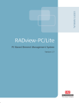
Figure 1-1 illustrates a typical application, where RIC-155GE transports Gigabit
Ethernet traffic over SDH/SONET infrastructure.
Central Site
Remote Site
RIC-155GE
RIC-155GE
Fiber
Fiber
SDH/SONET
STM-1/OC-3c
Data
Management
STM-1/OC-3c
ADM
ADM
IP
Network
Gigabit Ethernet
Switch/Router
Network
Management
Station
Gigabit Ethernet
Switch/Router
Figure 1-1. Typical Ethernet Access Application
Features
RIC-155GE is an Ethernet to SDH/SONET converter. It provides Ethernet access
over SONET/SDH.
The RIC-155GE has:
•
A single Gigabit Ethernet user interface
•
A single STM-1 POS interface
•
A single Fast Ethernet port for management
•
Control port for out-of-band management
•
Optional dry contact alarm connector.
User Ethernet Interface
The Gigabit Ethernet user interface operates in full duplex, supporting regular size
(1668 bytes) frames. RIC-155GE supports the following Ethernet interfaces:
•
1000BaseSx
•
1000BaseT.
STM-1/OC-3c POS Interface
RIC-155GE converts Gigabit Ethernet frames into POS frames and vice versa. The
fiber optic interface of the unit uses a single mode 1310 nm short or long haul
laser diode transmitter or a multimode 1310 nm transceiver.
SDH/SONET mode is user-configurable. Jitter output and tolerance complies with
G.825 requirements.
The STM-1/OC-3c port supports an egress priority queue. (Priority according to
VLAN priority, in VLAN aware bridge mode).
Order from: Cutter Networks
1-2
Overview
ph:727-398-5252/fax:727-397-9610
www.bestdatasource.com
RIC-155GE Ver. 1.10
Installation and Operation Manual
Chapter 1 Introduction
Bridging
RIC-155GE provides a bridging function between its different bridge ports:
•
User Ethernet port
•
STM-1/OC-3c POS interface
•
Fast Ethernet management port
•
Internal host.
The internal bridge operates in VLAN-unaware (transparent) or VLAN-aware
modes (with VLAN double tagging (stacking)).
VLAN-Unaware Mode
Ethernet packets (tagged or untagged) received from one of the bridge ports
defined in the previous paragraph, is forwarded according to its destination MAC
address. Thus, there is only a single queue towards the SDH/SONET interface.
When operating in the VLAN-unaware mode, the internal bridge supports the
following functions:
•
Learning of up to 2048 MAC addresses
•
Configuration of the aging time
•
VLAN tagged frames transparency (forwarding according to MAC only)
•
MAC table viewing (learnt MACs).
In this mode, forwarding of packets between the GbE data port and FE MNG port
is blocked (locally in the device), however, there is no end-to-end separation
between the GbE and FE data.
VLAN-Aware Mode
In the VLAN-aware mode, packets at the GbE ingress are VLAN tagged or double
tagged with VID=PVID.
Frames at the FE ingress are tagged or double tagged with VID=PVID, the internal
host PVID is the same as the FE PVID. These are internal settings and are
transparent to the user application as the extra VID tag is stripped at FE and GbE
egress.
In VLAN aware mode, forwarding is performed according to MAC and VLAN
PVID. Using the internal setting of double tagging ensures total separation of FE
and GbE traffic. Host traffic has the same internal VID as the FE tag, so
management is allowed only from FE MNG port and is totally separated from GbE
user traffic.
In this mode four priorities for user traffic are supported at the POS interface
according to the frame VLAN priority.
When operating in the VLAN-aware mode, the internal bridge supports the
following functions:
•
Learning and forwarding according to MAC address and VID
•
Learning of up to 2048 MAC table entries (MAC + VID pairs)
Order from: Cutter Networks
RIC-155GE Ver. 1.10
ph:727-398-5252/fax:727-397-9610
www.bestdatasource.com
Overview
1-3
Chapter 1 Introduction
Installation and Operation Manual
•
Configuration of the aging time
•
MAC table viewing (learnt MACs)
•
Double-tagging – all frames are tagged. An untagged frame becomes tagged
and a tagged frame becomes double-tagged. The added tag is stripped at FE,
GbE egress.
Management
Setup, control and monitoring of status and diagnostics information can be
performed using one of the following methods:
• Inband management:
Local and remote management via the Ethernet port for management
Local and remote management via the Gigabit Ethernet user port (VLAN
unaware mode only)
•
Out-of-band management:
Local management via ASCII terminal connected to the V.24 (RS-232) DCE
control port
Local management via dedicated 10/100BaseT management port.
ConfiguRAD is a user-friendly Web-based element management system for remote
device configuration and maintenance. It is embedded in RIC-155GE and
provided at no extra cost. ConfiguRAD can be run from any standard Web
browser.
Diagnostics
RIC-155GE supports activation of the following diagnostic loopbacks:
•
STM-1 timed external loopback (towards STM-1/OC-3c link)
•
STM-1 timed internal loopback (towards RIC-155GE).
Statistics
Provides statistics and counters capability in the physical Ethernet and network
interface level in 15-minute intervals (SONET/SDH physical layer only).
Compact Size
RIC-155GE is a compact unit, 1U high and half the width of a standard 19-inch
rack. It can be mounted in a rack or used as a standalone unit.
Order from: Cutter Networks
1-4
Overview
ph:727-398-5252/fax:727-397-9610
www.bestdatasource.com
RIC-155GE Ver. 1.10
Installation and Operation Manual
1.2
Chapter 1 Introduction
Physical Description
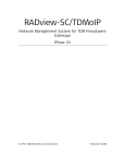
RIC-155GE is a 1U high standalone or rack mountable device. Figure 1-2 shows a
three dimensional view of RIC-155GE with Gigabit Ethernet and STM1/OC-3c
network interfaces, and the optional Alarm connector.
Figure 1-2. RIC-155GE 3-D View
LEDs, interface and control connectors are located on the front panel. For more
information see Chapter 2.
The power connector is located on the rear panel. For more information, see
Technical Specifications.
1.3
Functional Description
This section describes the major functional features of RIC-155GE.
Interfaces
SDH/SONET Interface
The SDH/SONET port supports STM-1/OC-3c over optical interface. The optical
interface can be either single mode short haul according to G.957 S 1.1, single
mode long haul according to G.957 L 1.1, or multimode according to G.825.
RIC-155GE can operate in either SONET or SDH mode to support the differences
in framing parameters.
Note
The choice of SONET or SDH affects the terminology of the physical layer, so that
the display of counters, alarms and log messages varies according to the standard
that was selected.
Order from: Cutter Networks
RIC-155GE Ver. 1.10
ph:727-398-5252/fax:727-397-9610
www.bestdatasource.com
Functional Description
1-5
Chapter 1 Introduction
Installation and Operation Manual
Table 1-1. SDH/SONET Terminology
SDH
SONET
MS-AIS
Line AIS
AU-AIS
Path AIS
MS-FERF
Line FERF/RDI
HP-FERF
Path FERF/RDI
RS-BIP (B1)
Section BIP
MS-BIP (B2)
Line BIP
HP-BIP (B3)
Path BIP
MS-FEBE
Line FEBE
HP-FEBE
Path FEBE
Ethernet Interface
The Ethernet physical interface is 10/100BaseT over UTP, RJ-45 connector port.
The Ethernet port supports 10/100Mbps rates and either full- or half-duplex
operation. Autonegotiation for automatic speed and duplex mode are supported
as well.
The Ethernet port supports Ethernet and 802.3 standards.
Gigabit Ethernet Interface
The Gigabit Ethernet physical interface is either an optical 1000BaseSx or an
electrical 1000BaseT. 1000 Mbps full-duplex is supported with an option to
enable or disable autonegotiation.
The Gigabit Ethernet interface supports Ethernet and 802.3 standards.
Bridge Operation Modes
This section describes the bridge operation mode, default bridge settings and
management access.
RIC-155GE default mode is VLAN unaware. In this mode the bridge is configured
to VLAN unaware and the bridge ports are automatically attached;
ETH MNG, Gigabit Ethernet user, STM1 POS and internal host.
No further configuration is needed except for defining the device host.
Bridge parameters such as aging time may be changed.
In this mode RIC-155GE is a transparent bridge with no separation between ETH
MNG traffic and GbE user traffic.
Note
In this mode, traffic between local GbE user and ETH MNG is blocked.
Management access (local and remote) is available from both ETH MNG and GbE
user port.
Order from: Cutter Networks
1-6
Functional Description
ph:727-398-5252/fax:727-397-9610
www.bestdatasource.com
RIC-155GE Ver. 1.10
Installation and Operation Manual
Chapter 1 Introduction
When the RIC-155GE is configured as a VLAN aware bridge, the bridge is
automatically configured to a predefined VLAN setting. This VLAN setting ensures
transparent service (transparent bridge), but with a total separation between ETH
MNG and GbE user traffic. This setting ensures that local and remote access to the
device host is only available from ETH MNG port.
Traffic separation is achieved by internal configuration of the ETH MNG, GbE user
and host bridge port to the double-tagging mode, and assigning internal VLANs in
a way that ETH MNG and internal host are on a different VLAN than the GbE user
port. As the bridge is VLAN aware, total separation of forwarding is achieved.
The VLAN double tagging is transparent to the user data as it is stripped from the
frame at the GbE/FE Tx egress. Internal VLAN double tagging completely separates
ETH MNG and GbE user port, even if the same VLANs are being used by attached
networks. However, ingress filtering (blocking certain user VLANs) is not possible.
Bridge detailed description
RIC-155GE provides a bridging function between its different bridge ports:
• User Ethernet port
•
STM-1/OC-3c POS interface
•
Fast Ethernet management port
•
Internal host.
The internal bridge operates in VLAN-unaware (transparent) or VLAN-aware
modes, with VLAN double-tagging (VLAN stacking).
1 GbE User Traffic
1 GbE User Traffic
STM-1/OC-3c
10/100BT Management Traffic
SDH/SONET
STM-1/OC-3c
RIC-155GE
RIC-155GE
10/100BT Management Traffic
Network
Management
Station
Figure 1-3. VLAN-Aware Mode Management Diagram
VLAN-Aware Mode
In the VLAN-aware mode the frame forwarding is based on the MAC addressing
and VLAN tagging. RIC-155GE uses tagging and double-tagging methods to ensure
ETH MNG and GbE user data separation.
When RIC-155GE receives frames (tagged or untagged), it tags or double tags them
with a port default VID and forwards them according to the new VID and MAC. By
using double tagging for the Gigabit Ethernet port, STM-1/OC-3c port, management
port and the host, it is possible to separate data and management traffic, even without
knowing user traffic parameters (tagged, untagged, user VLANs).
Order from: Cutter Networks
RIC-155GE Ver. 1.10
ph:727-398-5252/fax:727-397-9610
www.bestdatasource.com
Functional Description
1-7
Chapter 1 Introduction
Installation and Operation Manual
At the STM-1 port, RIC-155GE maps packets according to the VLAN priority bits
into four fixed priority egress queues enabling differentiation between various user
applications in case of congestion.
The mechanism of the VLAN-aware bridge can be described as five different
processes:
•
Ingress – checks each frame entering the bridge to decide if and how this
frame should be passed on to the forwarding process
•
Learning – learns new MAC table entries (MAC VID pairs)
•
Aging – checks the forwarding MAC table periodically
•
Forwarding – decides to which bridge port/ports to forward the frame
•
Transmission – selects the format of the transmitted frame at the output port,
with or without VLAN.
Ingress Process
The ingress process is composed of three processes: frame admission, ingress
filtering and PVID assignment to untagged/priority only tagged frames.
•
Frame admission – all frames, tagged and untagged, coming from the port
are admitted.
•
PVID Assignment.
In VLAN-aware mode, each received frame entering the bridge is associated
with a single VLAN ID (VID). In case the received frame does not have a VID
(untagged or priority only tagged frames), a specific PVID will be assigned to
these frames before they pass to the forwarding process. Every frame will be
tagged with a PVID. Frames already having a VID will be double tagged.
For untagged frames that were tagged during this process to VID=PVID, a
priority tag of “0” will be assigned at the VLAN priority field.
Double-tagged frames will copy the priority tag of the original frame priority
tag.
Frames that pass this stage are submitted to the learning and forwarding processes.
Learning Process
The learning process observes the source MAC address (SA) and the PVID assigned
at ingress, and updates the forwarding database with the MAC VID pair.
Order from: Cutter Networks
1-8
Functional Description
ph:727-398-5252/fax:727-397-9610
www.bestdatasource.com
RIC-155GE Ver. 1.10
Installation and Operation Manual
Chapter 1 Introduction
Aging Process
The aging process checks the forwarding MAC table periodically. Each dynamic
entry aging time period that has exceeded the configured Aging Time Limit is
deleted. The aging time period is the period of time since the last frame for this
entry has entered the bridge. The periodic check of the MAC table (aging time
intervals), results in actual aging time that can reach up to twice the value that was
configured by the user.
Forwarding Process
The forwarding process is performed on the basis of the frame destination MAC
VID pair. The frame is forwarded to bridge port that was specified in the MAC
table for this MAC VID pair entry.
Tagged and double-tagged frames are forwarded according to the PVID that was
attached to that frame during the ingress process.
In VLAN aware mode, internal settings of PVID and VLAN ports members ensures
forwarding according to MAC address learnt from ports that share the same PVID
(FE and internal host share the same PVID, but are different from the PVID
assigned to GbE user port)
•
Flooding:
If the (DA, VID) pair is not learned, and does not exist in the MAC table,
the frame will be transmitted to all bridge ports that are associated with the
same VLAN ID as the frame’s PVID )internal settings GbE and STM1 as one
VLAN domain and FE, Internal host as a second domain.
Multicasts and broadcasts are also flooded only through the bridge ports
whose VLAN ID equals the frame’s PVID.
Transmission Process
After the forwarding process matches the destination bridge port/ports to which
the frame should be transmitted to, the transmission process transmits it while
stripping the added PVID so that separation is totally transparent to end user
traffic.
QoS Mapping
In VLAN-aware mode, the RIC-155GE STM1 port supports QoS mapping
according to VLAN priority tag.
Four priority queues are available; each VLAN priority may be mapped to a certain
priority queue.
VLAN-Unaware Mode
In this mode the bridge forwarding ignores the VLAN ID of VLAN tagged frames.
Each Ethernet packet received from Gigabit Ethernet user port is forwarded
according to its destination MAC address.
Order from: Cutter Networks
RIC-155GE Ver. 1.10
ph:727-398-5252/fax:727-397-9610
www.bestdatasource.com
Functional Description
1-9
Chapter 1 Introduction
Installation and Operation Manual
Ingress Process
All frames are accepted in this mode: untagged, priority-tagged or VLAN-tagged.
Learning and forwarding is based on the MAC addresses, with no regard to the
VLAN. This mode is sometimes regarded to as transparent mode, due to
“tag transparency”.
Learning Process
The learning process observes the source MAC address (SA) of the received frame
and updates the forwarding database (FDB) with the MAC and the bridge port that
the frame was received from. (FDB is also referred to as MAC table).
The learning process inserts a new entry into the MAC table. This entry consists of
MAC and bridge port.
•
If the MAC already exists for the same bridge port, the aging time will be
updated
•
If the MAC already exists, but for a different bridge port, (dynamic entry) the
new entry will override the existing one
Aging Process
The aging process checks the forwarding MAC table periodically. Each dynamic
entry aging time period that has exceeded the configured Aging Time Limit is
deleted. The aging time period is the period of time since the last frame for this
entry has entered the bridge. The periodic check of the MAC table (aging time
intervals), results in an actual aging time that can reach up to twice the value that
was configured by the user.
Forwarding Process
The forwarding process is performed based on the frame MAC Destination
Address (MDA). The frame is forwarded to the Bridge/port specified in the MAC
table for this MAC.
Frames are forwarded, dropped or flooded at this stage for the following reason:
•
Forwarded: A frame will be forwarded according to its DA, to the bridge port
where its DA was learnt.
•
Dropped: if the port for that DA entry in the MAC table is the port on which
the frame was received, the frame will be dropped
•
Flooded:
If there is no information regarding the DA in the MAC table then the
frame is flooded to all ports
Frames with multicast or broadcast address are flooded to all ports.
Transmission Process
In this bridge mode (VLAN-unaware), the frames are transmitted unchanged – no
tags are added or removed.
Order from: Cutter Networks
1-10
Functional Description
ph:727-398-5252/fax:727-397-9610
www.bestdatasource.com
RIC-155GE Ver. 1.10
Installation and Operation Manual
Chapter 1 Introduction
Fault Propagation
In order to trigger the redundancy path mechanisms of the Ethernet traffic, it is
necessary to notify the Ethernet device (router or switch), connected to the
RIC-155GE port, of the SDH/SONET path failure. For this purpose the fault
propagation mechanism is available.
If enabled, SDH/SONET alarms propagate and bring down the Gigabit Ethernet
link. The Gigabit Ethernet link down can optionally propagate and cause alarms to
be sent at the SDH/SONET egress.
Figure 1-4 shows the fault propagation behavior.
Figure 1-4. Fault Propagation
Figure 1-5 shows Gigabit Ethernet to SDH/SONET fault propagation.
Figure 1-5. Gigabit Ethernet to SDH/SONET Fault Propagation
RIC-155GE waits for ten consecutive seconds with no alarms, before recovering.
Between SDH/SONET to Gigabit Ethernet, the Gigabit Ethernet link will recover
only after ten seconds with no alarms on the SDH/SONET port.
Between Gigabit Ethernet to SDH/SONET, the SDH/SONET stops sending alarms
only after ten consecutive seconds that the Gigabit Ethernet link is operating.
Management
RIC-155GE enables its performance monitoring locally from an ASCII terminal, or
from a remote site using Telnet, ConfiguRAD Web based application, or
RADviewLite SNMP-based fault management software.
Log Events File
Events are stored and time-stamped in an event log file that is saved in a
non-volatile memory. Up to 2000 cyclic entries are maintained.
Order from: Cutter Networks
RIC-155GE Ver. 1.10
ph:727-398-5252/fax:727-397-9610
www.bestdatasource.com
Functional Description
1-11
Chapter 1 Introduction
Installation and Operation Manual
Inband Management
RIC-155GE supports inband management via Telnet, Web, and SNMP.
Configuration, monitoring and statistics are available.
Out-of-Band Management
RIC-155GE enables full configuration and diagnostics via an ASCII terminal. The
ASCII terminal is connected to the Control Port in the RIC-155GE front panel.
ASCII terminal activation is provided in Chapter 3 including general instructions for
navigating through the system menus and windows and modifying data.
Security
ASCII terminal, Telnet and Web access are password protected. After a period of
15 minutes of inactivity during which no character was sent to the terminal the
system exits to the password screen.
If there are three attempts to enter the system using a wrong password, the
RIC-155GE will disallow additional attempts and access shall be possible only by
obtaining a new access code from RAD technical support.
RIC-155GE supports the following access authorization levels:
•
Super user mode for configuration and monitoring
•
User mode for monitoring only
Events/traps for local terminal login and for invalid (failed) login are sent to the log.
Statistics Collection and Alarms
RIC-155GE supplies extensive statistics on all levels. STM1 statistics are gathered in
15-minute period intervals. The built in volatile memory saves 24 intervals. GbE
and FE statistics are not saved in intervals.
For more information, see Chapter 6.
Alarm Connector
RIC-155GE has an optional alarm connector including major and minor alarm dry
contacts.
A Major alarm is set when one of the following occurs:
•
LOS
•
LOF
•
LOP
•
Line AIS
•
Path AIS
•
SLM
•
Loss of integrity of the user GbE port.
Order from: Cutter Networks
1-12
Functional Description
ph:727-398-5252/fax:727-397-9610
www.bestdatasource.com
RIC-155GE Ver. 1.10
Installation and Operation Manual
Chapter 1 Introduction
A Minor alarm is set when one of the following occurs:
•
Line RDI
•
Path RDI
•
Line BIP (above predefined threshold)
•
Path BIP (above predefined threshold)
•
Line FEBE (above predefined threshold)
•
Path FEBE (above predefined threshold)
SDH/SONET Fault Localization (AIS/RDI)
•
Line RDI – sent upon LOS, LOF or Line AIS
•
Path RDI – sent upon LOS, LOF, Line AIS, LOP, SLM, Path AIS or LCD
•
Section FEBE sent upon section BIP recognition
•
Line FEBE sent upon line BIP recognition
•
Path FEBE sent upon path BIP recognition.
Diagnostics
There are several types of diagnostics and troubleshooting procedures. For more
information see Chapter 6.
•
Loop-based troubleshooting:
SDH/SONET port-timed external loop, towards line
SDH/SONET port-timed internal loop, towards device.
•
Ping tests to manager’s station
•
Events/Traps
Hierarchically layered traps, event traps resulting from events that were
already reported and are still active will not be sent. For example, LOF event
traps will not be sent if LOS, was sent and the physical layer problem still
exists.
Physical layer events/traps for STM1, BIPs and FEBE are threshold triggered
(the event/trap will be sent only if the threshold was exceeded). The threshold
is configurable from 1 to 8000 events per second. One event is an errored
frame.
Traps can be disabled when a manager masks them. Events to the event log
cannot be disabled. For more information, refer to Chapter 6.
Order from: Cutter Networks
RIC-155GE Ver. 1.10
ph:727-398-5252/fax:727-397-9610
www.bestdatasource.com
Functional Description
1-13
Chapter 1 Introduction
1.4
Installation and Operation Manual
Technical Specifications
1
User Ethernet Number of Ports
Interface
Compatibility
Relevant sections of IEEE 802.3u, 802.3x, 802.1p and
802.3q
Data Rate
1000 Mbps
Frame Size
Regular (1668 bytes)
Fiber Optic Interface
LC Connector
Electrical Cable Type
Cat. 5 cable
Options
1000BaseSx
1000BaseT
STM-1 POS
Interface
Number of Ports
1
Connector
SC
Data Rate
155 Mbps
Options
Single mode 1310 short haul G.957 S1.1
Single mode long haul G.957 L1.1
Multimode ANSI T1.646
Internal
Bridge
Number of Ports
Four:
• Gigabit Ethernet
• 10/100BaseT management
• Local host
• STM-1 POS
LAN Table
Up to 2048 MAC addresses (learned)
Operation Mode
VLAN-aware, VLAN-unaware
Buffer
3150 frame buffer
Filtering and
forwarding
Up to 287,000 pps (VLAN unaware)
Compliance
10/100BT
Management Operation
Port
Control Port
IEEE 802.3
Full duplex, autonegotiation
Frame Size
Up to 1668 bytes
Connector
RJ-45
Interface
RS-232/V.24 (DTE asynchronous)
Data Rate
9.6, 19.2, 38.4, 57.6, 115.2 kbps
Connector
DB-9, female
Order from: Cutter Networks
1-14
Up to 270,000 pps (VLAN aware)
Technical Specifications
ph:727-398-5252/fax:727-397-9610
www.bestdatasource.com
RIC-155GE Ver. 1.10
Installation and Operation Manual
Chapter 1 Introduction
Alarm
Connector
Connector
DB-9 female
Electrical
Characteristics
Dry Contact, 30V/2A
Monitoring
Statistics
STM-1/OC-3c physical layer statistics
STM-1/OC-3c frame counters
Gigabit Ethernet physical layer statistics and frame
counters
10/100BaseT management port Ethernet physical layer
statistics and frame counters
10/100BaseT management port Rx/Tx frame counters
Indicators
On: RIC-155GE is powered
PWR (green)
Off: RIC-155GE is off
On: SONET/SDH LOS/LOF/LOP/AIS, link down at
Gigabit Ethernet, Self-test failed
ALM (red)
Off: No Alarm
On: link OK
ETH LINK (Green)
Off: link is disconnected
Blinking: Ethernet frame received or sent within the last
second
ACT (Yellow)
Off: No frame received or sent within the last second
On: STM-1 port is synchronized
SYNC (green)
Off: LOS/LOF/LOP/AIS
Blinking: RDI detected
Power
Physical
AC Source
100 to 240 VAC (±10%), 50 to 60 Hz
DC Source
-48 VDC (±10%) or 24 VDC (±10%)
Power Consumption
20W
Height
43 mm (1.7 in)
Width
215 mm (8.5 in)
Depth
300 mm (11.8 in)
Weight
2.1 kg (4.7 lb)
Environment Temperature
Humidity
Order from: Cutter Networks
RIC-155GE Ver. 1.10
0–50°C (32–122°F)
Up to 90%, non–condensing
ph:727-398-5252/fax:727-397-9610
www.bestdatasource.com
Technical Specifications
1-15
Chapter 1 Introduction
Installation and Operation Manual
User Port Interface
The user interface of RIC-155GE is a Gigabit Ethernet port. The interface
specifications according to the ordering options are shown below:
•
1000BaseSx (Table 1-2)
•
100BaseT (Table 1-3).
Table 1-2. 1000BaseSx Interface Specifications
Specifications
Ethernet Ports
Interface
1000BaseSx Ethernet Interface
Standards
Ethernet, IEEE 802.3
Data Rate
1000 Mbps
Interface type
Optical LC connector
Range
220m/720 ft over 62.5 µm multimode fiber
or 500m/1640 ft over 50 µm multimode fiber
Wavelength
850 nm
Optical input range
0 to −17 dBm
Optical output power
0 to −9.5 dBm
Duplex modes
Full duplex
Table 1-3. 100BaseT Interface Specifications
Specifications
Ethernet Ports
Interface
1000BaseT Ethernet Interface
Standards
Ethernet, IEEE 802.3
Framing
N/A
Data Rate
1000 Mbps
Interface type, connector
Electrical, RJ-45
Range
100 meters/328 feet on UTP category 5 cables
Duplex modes
Full duplex
Order from: Cutter Networks
1-16
Technical Specifications
ph:727-398-5252/fax:727-397-9610
www.bestdatasource.com
RIC-155GE Ver. 1.10
Installation and Operation Manual
Chapter 1 Introduction
Network Port Interfaces
The SDH/SONET network interface is an STM1/OC-3c interface. Two options are
available:
•
155 Mbps, single mode 1310 nm, short haul
•
155 Mbps, single mode 1310 nm, long haul.
Table 1-4. STM1/OC-3c Network Interface Specifications: Long Haul
Specifications
STM-1/OC-3c port
Interface
155 Mbps, single mode 1310 nm, long haul
Standards
G.957 (L 1.1) G.825 (jitter)
Framing
STS3C/STM-1
Data Rate
155 Mbps
Interface type, connector
Optical, SC
Range
40 km/25 miles
Wavelength
1310 nm
Optical output power
0 to -5 dBm
Optical input range
-10 to -34 dBm
Table 1-5. STM1/OC-3c Network Interface Specifications: Short Haul
Specifications
STM1/OC-3c port
Interface
155 Mbps, single mode 1310 nm, short haul
Standards
G.957 (S 1.1) G.825 (jitter)
Framing
STS3C/STM-1
Data Rate
155 Mbps
Interface type, connector
Optical, SC
Range
15 km/9.4 miles
Wavelength
1310 nm
Optical output power
-8 to -15 dBm
Optical input range
-8 to -28 dBm
Order from: Cutter Networks
RIC-155GE Ver. 1.10
ph:727-398-5252/fax:727-397-9610
www.bestdatasource.com
Technical Specifications
1-17
Chapter 1 Introduction
Order from: Cutter Networks
1-18
Technical Specifications
Installation and Operation Manual
ph:727-398-5252/fax:727-397-9610
www.bestdatasource.com
RIC-155GE Ver. 1.10
Chapter 2
Installation and Setup
This chapter discusses RIC-155GE installation and setup, and includes the
following sections:
• Introduction
•
Site Requirements and Prerequisites
•
Package Contents
•
Connecting the Interface Cables
•
Connecting the Power Cables.
2.1
Introduction
The RIC-155GE device is intended for installation on desktop, 19” racks and walls.
The following mounting kits are available from RAD:
•
RM-35 for mounting one or two RIC-155GE units into a 19” rack
•
WM-35 for mounting one RIC-155GE unit on a wall.
After installing the unit, configure the RIC-155GE using an ASCII terminal
connected to the RIC-155GE control port. The RIC-155GE configuration
procedures are described in Chapter 3 and Chapter 4. If problems are
encountered, refer to Chapter 6.
Warning
No internal settings, adjustment, maintenance and repairs should be
performed by either the operator or the user. Such activities must be
performed only by skilled personnel who are aware of the hazards involved.
Always observe standard safety precautions during installation, operation and
maintenance of this product.
2.2
Site Requirements and Prerequisites
AC-powered RIC-155GE units should be installed within 1.5 meters (5 feet) of an
easily accessible grounded AC outlet capable of furnishing the required supply
voltage, in the range of 100 to 240 VAC, 50 or 60 Hz.
Allow at least 90 cm (36 in) of frontal clearance for operator access. For continuous
product operation allow at least 10 cm (3.9 in) of frontal clearance and at least 15 cm
(5.9 in) at rear of the unit, for cable connections and ventilation. For proper ventilation,
keep at least 2.5 cm (0.9 in) clearance from the sides and top of the product.
The ambient operating temperature of RIC-155GE is 0° to 50° C (32° to 122°F), at
a relative humidity of up to 90%, non-condensing.
Order from: Cutter Networks
RIC-155GE Ver. 1.10
ph:727-398-5252/fax:727-397-9610
www.bestdatasource.com
Site Requirements and Prerequisites
2-1
Chapter 2 Installation and Setup
2.3
Installation and Operation Manual
Package Contents
RIC-155GE package contains the following items:
•
RIC-155GE unit
•
AC power cord
•
RM-35 rack-mount kit (if ordered)
•
WM-35 wall-mount kit (if ordered).
2.4
Connecting the Interface Cables
RIC-155GE includes one Ethernet port, one Gigabit Ethernet port and one
SDH/SONET port. The SDH/SONET port supports a variety of interfaces (in
accordance with the ordering option). In addition, RIC-155GE includes a Control
port for connection to an ASCII terminal or an out-of-band management station
(via a straight RS-232 cable).
To connect the user interface:
•
Connect the Ethernet cable to the designated port on the front panel.
To connect the network interface:
•
Connect the SDH/SONET interface to the designated port on the front panel.
To connect the RIC-155GE to an ASCII terminal:
•
2.5
Warning
Connect the RS-232 cable to the CONTROL port on the front panel.
Connecting the Power Cables
Before switching on this unit and connecting or disconnecting any other cable,
the protective earth terminals of this unit must be connected to the protective
ground conductor of the mains power cord. If you are using an extension cord
(power cable) make sure it is grounded as well.
Any interruption of the protective (grounding) conductor (inside or outside the
instrument) or disconnecting of the protective earth terminal can make this
unit dangerous. Intentional interruption is prohibited.
Order from: Cutter Networks
2-2
Connecting the Power Cables
ph:727-398-5252/fax:727-397-9610
www.bestdatasource.com
RIC-155GE Ver. 1.10
Installation and Operation Manual
Warning
Chapter 2 Installation and Setup
RIC-155GE is equipped with a laser diode.
Please observe the following precautions:
• Before turning on the equipment, make sure that the fiber optic cable is
intact and is connected to the transmitter.
• Do not look into a laser connector when the power is turned on, a laser can
cause eye damage.
• Do not use broken or unterminated fiber-optic cables/connectors.
ATTENTION: The laser beam may be invisible!
Connecting AC Power
AC power is supplied to the RIC-155GE through a standard 3-prong plug.
AC power should be supplied via a 1.5m (5 ft) standard power cable terminated
by a standard 3-prong socket. A cable is provided with the unit.
To connect AC power:
1. Connect the power cable to the power connector on the RIC-155GE rear
panel.
2. Connect the power cable to the mains outlet.
The unit will be turned on automatically upon connection to the mains.
Connecting DC Power
A special IEC 60320 adapter for -48/-60 VDC power connection is supplied with
the unit. 24 VDC RIC-155GE units have a terminal block DC inlet and adapter
supplied with the unit.
To connect DC power:
•
Order from: Cutter Networks
RIC-155GE Ver. 1.10
Refer to the DC power supply connection supplements for instructions how to
wire the DC adapters, and to the Handling Energized Products section.
ph:727-398-5252/fax:727-397-9610
www.bestdatasource.com
Connecting the Power Cables
2-3
Chapter 2 Installation and Setup
Order from: Cutter Networks
2-4
Connecting the Power Cables
Installation and Operation Manual
ph:727-398-5252/fax:727-397-9610
www.bestdatasource.com
RIC-155GE Ver. 1.10
Chapter 3
Operation
This chapter discusses general RIC-155GE operation, and includes the following
sections:
•
RIC-155GE front panel indicators
•
Operating procedures (power-on and power-off)
•
Getting started instructions
•
Overview of menu operations.
For detailed information on configuring RIC-155GE, see Chapter 4.
3.1
Turning RIC-155GE On
To power up the RIC-155GE:
•
Connect the AC mains cable to the AC connector on the rear panel. Refer to
Chapter 2.
After power-up, check the LED indicators for proper operation. Refer to Table 3-1.
For information on accessing RIC-155GE via an ASCII terminal, see Connecting
RIC-155GE to an ASCII Terminal.
3.2
Controls and Indicators
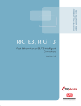
The front panel of RIC-155GE includes a series of LED indicators that show the
current operating status of the unit. Figure 3-1 shows the RIC-155GE front panel of
the unit. Table 3-1 lists and describes the RIC-155GE indicators.
RIC-155GE
PWR
ALM
MNG
LINK
ACT
ALARMS
LINK
DATA
ACT
CONTROL
155 Mbps
SYNC
Figure 3-1. RIC-155GE Front Panel
Order from: Cutter Networks
RIC-155GE Ver. 1.10
ph:727-398-5252/fax:727-397-9610
www.bestdatasource.com
Controls and Indicators
3-1
Chapter 3 Operation
Installation and Operation Manual
Table 3-1. RIC-155GE LEDs
Name
LED Color
Function
PWR
Green
On: RIC-155GE is powered
Off: RIC-155GE is off
ALM
RED
On: LOS/LOF/LOP/AIS at SONET/SDH, Link down at Giganet Ethernet,
self-test failed
Off: No Alarm
ETH LINK
Green
On: Link OK
Off: Link is disconnected
ETH ACT
Yellow
Blinking: Frame received or sent within the last second
Off: No frame received or sent within the last second
Network
SYNC
Green
On: STM1 port is synchronized (no alarms)
Off: LOS, LOF, LOP, AIS
Blinking: RDI detected
3.3
Default Settings
Configuration parameters in RIC-155GE may or may not have defaults.
Configuration parameters that have default values fall into one of two categories:
•
Defaults that are configured. For example, terminal baud rate, which is 19200
and set on power up. These defaults are presented on the screen.
•
Defaults that are not configurable. These defaults are not visible when
entering the screen and are presented by a blank field. They show up after a
‘Save’ operation is done on the particular screen.
Configuration parameters that do not have default values must have values entered
in their respective fields or the Save operation will fail.
Table 3-2. RIC-155GE Default Settings
Parameter
Default Value
System > Management
Set Host IP address
0.0.0.0
Set Subnet Mask
0.0.0.0
Host Tagging
Untagged
Host VLAN
None
Host VLAN Priority
None
Authentication failure trap
ON
Trap community
Public
Read community
Public
Write community
Public
Manager IP Address
0.0.0.0
Order from: Cutter Networks
3-2
Default Settings
ph:727-398-5252/fax:727-397-9610
www.bestdatasource.com
RIC-155GE Ver. 1.10
Installation and Operation Manual
Chapter 3 Operation
Table 3-2. RIC-155GE Default Settings (Cont.)
Parameter
Default Value
Alarm trap
All masked
System trap
ON
System > Terminal
Baud rate
19200
Physical Layer > SDH/SONET
Tx Clock Source
Loopback
Frame Type
SDH
Thresholds
2400
Physical Layer > Ethernet
Auto negotiation
Enable
Max capacity advertised
100BaseT Full Duplex
Default Type
100BaseT Full Duplex
Bridge
Bridge type
VLAN unaware
Aging time
300
Bridge > Bridge port parameters
Priority
All VLAN priorities mapped to lower priority
queue
Bridge > Bridge configuration >
Ethernet priority >
VLAN priority
POS priority
4
VLAN priority
0
3.4
Configuration Alternatives
RIC-155GE has several management options:
•
ASCII Terminal – connected to RIC-155GE via the RS-232 control port (see
Working with an ASCII Terminal)
•
Telnet – access to the configuration screens via any Telnet application
•
RADview – RAD’s user-friendly SNMP-based GUI application
(refer to RADview-EMS/ATM RIC-155GE User’s Manual)
•
Other SNMP-based management applications
Order from: Cutter Networks
RIC-155GE Ver. 1.10
ph:727-398-5252/fax:727-397-9610
www.bestdatasource.com
Configuration Alternatives
3-3
Chapter 3 Operation
Installation and Operation Manual
Working with an ASCII Terminal
Both the RIC-155GE configuration and monitoring operations can be performed
locally, using an ASCII terminal connected to the control port. The following
functions are supported:
•
View system information
•
Modify configuration and mode of operation, including setting system default
values
•
View statistics and status
•
Perform diagnostics.
RIC-155GE configuration and system monitoring, including troubleshooting
procedures, can also be performed from a remote site using Telnet or a Web
application.
Connecting RIC-155GE to an ASCII Terminal
The ASCII terminal can be connected directly to the RIC-155GE Control port.
Use straight cable to connect directly between the Control Port and the ASCII
terminal.
Any standard ASCII terminal (a dumb terminal, or a PC running terminal emulation
application) that is equipped with a V.24/RS-232 communication interface can be
used to set up and configure the RIC-155GE.
To connect RIC-155GE to a control terminal:
1.
Make sure that all the RIC-155GE connectors are properly connected to the
appropriate media.
2.
Turn on the control-terminal PC and set its default port parameters to 19,200
baud, 8 bits/character, 1 stop bit, no parity, Flow control: None.
3.
Set the terminal emulator to VT100 emulation for optimal view of system
menus.
4.
If you are using Hyper Terminal, set the terminal mode to 132 column mode
for optimal view of system menus
(Properties->Settings->Terminal Setup->132 column mode).
5.
Power up the RIC-155GE.
The RIC-155GE displays the self-test result in the terminal. The PWR LED
on the right side of the front panel is green at the end of the test.
Login
To gain access to the main menu you must login first.
To login:
1.
Press ESC to enter the login screen.
The Login screen appears.
Order from: Cutter Networks
3-4
Configuration Alternatives
ph:727-398-5252/fax:727-397-9610
www.bestdatasource.com
RIC-155GE Ver. 1.10
Installation and Operation Manual
Chapter 3 Operation
User name
>
Password
>
Figure 3-2. Login Screen
2.
Note
Enter your user name (su for full configuration and monitoring access) and
then your password when prompted (the factory set password is 1234).
If the password is invalid in three consecutive attempts, the system will become
inaccessible.
User Name and Password
To enter as a supervisor:
This allows you to configure all parameters of RIC-155GE and to change the su
and user passwords.
1.
Type su for User Name.
2.
Press <Enter>.
3.
Type 1234 for Password.
4.
Press <Enter>.
To view the unit’s statistics:
This does not allow you to make configuration changes.
1.
Type user for User Name.
2.
Press <Enter>.
3.
Type 1234 for Password.
4.
Press <Enter>.
To set all passwords to the default value (1234):
•
Enter as su and delete the unit’s configuration through the Configuration
screens.
Using the Command Language
Refer to Figure 3-5 as a sample generic screen, to set up and configure RIC-155GE.
Not all the elements appear on all the screens.
•
Link to a sub menu, such as 1 or 2 on the sample screen. To reach a sub
menu, select either 1 or 2 and press <Enter>
•
Enter a value for a parameter (item 3). To enter a value, type 3, press
<Enter>, type the value and press <Enter>.
•
Select a value from a list (item 4). To select a value, type 4, press <Enter>,
select the value from the list and press<Enter>.
•
Table, to be filled with data, or viewed
Order from: Cutter Networks
RIC-155GE Ver. 1.10
ph:727-398-5252/fax:727-397-9610
www.bestdatasource.com
Configuration Alternatives
3-5
Chapter 3 Operation
Installation and Operation Manual
Save command is shown only when at least one menu item has been changed, but
illegal changes, such as a parameter out of range, shall not permit the Save
operation to be carried out.
The area at the bottom of the screen is allocated for online messages. These
messages carry online interactive user information containing configuration
instructions and fail information with possible reasons of the failure.
Terminal Hot Keys
Terminal hot keys are provided per screen to enhance the functionality that is
required of that screen. The available hot keys are listed in the lower part of each
screen. The following hot keys are system keys, available on screens:
•
Esc – Return to previous menu
•
S or s – Save
•
D or d – Delete, for example to delete an item from the Data Base
•
! – Return to the main menu
•
& – Exit to password screen (to prevent unauthorized access after completing
the session)
•
X or x – Next item
•
F or f – Forward interval (statistic menus)
•
B or b – Backward interval (statistic menus)
•
@ - Full Screen – Allocate full screen for messages.
Screen path, at the bottom, showing the path to the specific screen that is being
currently displayed. Such as: Main>Configure>etc.
Viewing the Main Menu
Figure 3-3 shows the RIC-155GE Main Menu. Access to system configuration and
control functions is via this menu.
At any point and from any screen, you can press <Esc> repeatedly, backing up
until you reach the Main Menu.
Order from: Cutter Networks
3-6
Configuration Alternatives
ph:727-398-5252/fax:727-397-9610
www.bestdatasource.com
RIC-155GE Ver. 1.10
Installation and Operation Manual
Chapter 3 Operation
RIC-155GE - RAD data communications
RIC-155GE
1. Inventory
>
2. Configuration
>
3. Monitoring
>
4. Diagnostic
>
5. File utility
>
>
Main menu >
ESC-prev. menu; !-main menu; &-exit;
1 user(s)
Figure 3-3. Main Menu
The Main menu options are:
•
Inventory (type 1): View system information, HW/SW versions and HW
configuration
•
Configuration (type 2): Set and configure all the parameters required for the
operation of RIC-155GE
•
Monitoring (type 3): Monitor system performance and statistics
•
Diagnostics (type 4): Perform diagnostics
•
File utility (type 5): Upload/download application files, configuration files and
backup files.
Viewing the Configuration Menu
Figure 3-4 shows the RIC-155GE Configuration Menu. Access to the system
configuration is via this menu.
Main Menu
↓
2. Configuration
RIC-155GE - RAD data communications
Configuration
1. Quick Setup
>
2. System
>
2. Physical layer
>
3. Bridge
>
>
Main>Configuration>
ESC-prev. menu; !-main menu; &-exit;
1 user(s)
Figure 3-4. Configuration Menu
Order from: Cutter Networks
RIC-155GE Ver. 1.10
ph:727-398-5252/fax:727-397-9610
www.bestdatasource.com
Configuration Alternatives
3-7
Chapter 3 Operation
Installation and Operation Manual
The Configuration menu options are:
•
Quick Setup (type 1): Perform a quick setup when you are familiar with the
system and basic configuration modes
•
System (type 2): Configure the global system parameters, such as
Management, Terminal and others
•
Physical layer (type 3): Configure the physical layer parameters, such as
SONET/SDH, clocks, ETH rate and duplex mode
•
Bridge (type 4): Configure the bridge, change bridge parameters.
Type the number for the type of configuration; the appropriate menu appears.
Sample Functional Screen
Figure 3-5 shows a generic sample screen, with main items displayed.
Title line (For example: RIC-155GE Main menu
Short error message
1. Sub Menu>
2. Sub Menu>
3. Parameter X [Range] …… (value)
4. Parameter Y>
(Select value from the list)
5 Table Z []
prompt>
Help line message
Parameter help line such as “Esc” to return to previous menu
Main>Config>System.
-----------Division screen line -----------------Scroll message are
Figure 3-5. Sample Functional Screen
Table Sample Screen
Figure 3-6 shows a typical table. V ID and Names are the columns of parameters to
be defined.
Order from: Cutter Networks
3-8
Configuration Alternatives
ph:727-398-5252/fax:727-397-9610
www.bestdatasource.com
RIC-155GE Ver. 1.10
Installation and Operation Manual
Chapter 3 Operation
RIC-155GE - RAD data communications
VLAN Table
1. V ID
| NAME
|
>
Main>Configuration>Interworking>Bridge>VLAN Table
ESC-prev. menu; !-main menu; &-exit
1 user (s)
Figure 3-6. Sample Table Screen (VLAN)
The following hot keys are used to navigate a table screen:
•
Scroll:
I – left
r – right
u – up
d – down
•
Move:
L – left
R – right
U – up
D – down
•
Row:
a – add
t – remove
•
m – represents entry as menu
•
c – clear table
•
TAB – select next changeable cell
•
S <row number><column number> – select cell
Order from: Cutter Networks
RIC-155GE Ver. 1.10
ph:727-398-5252/fax:727-397-9610
www.bestdatasource.com
Configuration Alternatives
3-9
Chapter 3 Operation
Installation and Operation Manual
Menu Maps
The following figures illustrate the RIC-155GE menus. For detailed information on
configuring RIC-155GE, refer to Chapter 4.
Configuration
System
Physical Layer
Management
SONET/SDH
Tx clock source
Host IP
IP address
Frame type
IP mask
Threshold
Alarm Forwarding
Host Tagging
Authentication
failure trap
Ethernet
Trap Community
Auto negotiation
Read Community
MAX capability
advertised
Bridge
Bridge type
Aging Time
Bridge Port Configuration
(VLAN aware mode only)
Physical Port
Port parameters
Priority
POS Priority
VLAN Priority
Write Community
Default type
Manager list
MAC Table
Gigabit Ethernet
Manager IP
address
Auto negotiation
Alarm trap
Alarm Forwarding
System trap
Alarm trap mask
Send ping
Default GW
Terminal
Baud Rate
Change password
Date and time
Date
Time
Factory default
Reset
Figure 3-7. Configuration Menu Tree
Order from: Cutter Networks
3-10
Configuration Alternatives
ph:727-398-5252/fax:727-397-9610
www.bestdatasource.com
RIC-155GE Ver. 1.10
Installation and Operation Manual
Chapter 3 Operation
Diagnostics
Self test result
SDH/SONET
Figure 3-8. Diagnostics Menu Tree
Monitoring
Physical Layer
System
SONET/SDH
Event Log
SONET/SDH
Status
Read Log
File
POS
Statistics
Clear Log
File
Ethernet
Ethernet
Status
Ethernet
Statistics
Gigabit
Ethernet
Gigabit
Ethernet
Status
Gigabit
Ethernet
Statistics
Figure 3-9. Monitoring Menu Tree
Order from: Cutter Networks
RIC-155GE Ver. 1.10
ph:727-398-5252/fax:727-397-9610
www.bestdatasource.com
Configuration Alternatives
3-11
Chapter 3 Operation
3.5
Installation and Operation Manual
Turning RIC-155GE Off
To turn off RIC-155GE:
•
Disconnect the power cable from the rear panel.
Order from: Cutter Networks
3-12
Turning RIC-155GE Off
ph:727-398-5252/fax:727-397-9610
www.bestdatasource.com
RIC-155GE Ver. 1.10
Chapter 4
Configuration
This chapter describes the configuration procedures for RIC-155GE, and includes
the following sections:
•
Configuring RIC-155GE for Management
•
Configuring RIC-155GE for Operation
•
Additional Tasks
4.1
Configuring RIC-155GE for Management
Configuring the System Parameters
Main Menu
↓
2. Configuration
↓
2. System
The system menu allows access to system configuration sub-menus, such as:
Management, Terminal, Date & Time and to other basic system parameters.
System
RIC-155GE - RAD data communications
1. Management
>
2. Terminal
>
3. Date & Time
>
4. Factory default
...
5. Reset
...
>
Main>Configuration>System>
ESC-prev. menu; !-main menu; &-exit;
1 user(s)
Figure 4-1. System Menu
Note
If you select “Factory Default” or “Reset”, you will be asked to confirm your
selection by pressing Y or N.
You will also be asked if management configuration should be set to default.
Defining the Host IP
To define the Host IP:
•
Order from: Cutter Networks
RIC-155GE Ver. 1.10
From the Main Menu, select System > Management > Host IP.
ph:727-398-5252/fax:727-397-9610
www.bestdatasource.com
Configuring RIC-155GE for Management
4-1
Chapter 4 Configuration
Main Menu
↓
2. Configuration
↓
1 System
↓
1. Management
↓
1. Host IP
Host IP
Installation and Operation Manual
RIC-155GE - RAD data communications
1. IP address
... (-)
2. IP mask
... (-)
3. Host Tagging
... >
4. Host VLAN
... >
5. Host VLAN priority
... >
6. Authentication failure trap
>
(ON)
7. Trap community
... (public)
8. Read community
... (public)
9. Write community
... (public)
>
Main>Configuration>System>Management>Host IP>
ESC-prev. menu; !-main menu; &-exit;
1 user(s)
Figure 4-2. Host IP Menu
Table 4-1. Host IP Parameters
Parameter
Possible Values
Remarks
IP Address
0.0.0.0 to
255.255.255.255
Default: None
IP Mask
0.0.0.0 to
255.255.255.255
Default: None
Host Tagging
Tagged
Untagged
Specifies if the Management station is using tagged or untagged
frames. RIC-155GE must transmit in the same format, even if bridge
is in VLAN aware mode.
Default: Untagged
Host VLAN
1–4094
Set the VID of the packets sent by the host
Default: None
Host VLAN
priority
0–7
Set VLAN priority for packets sent by host. Relevant if Host Tagging is
set to Tagged
Default: None
Authentication
failure trap
ON
Authentication failure trap is generated when a system manager
attempts to set a RIC-155GE parameter with an incorrect community
value.
The authentication failure trap will not be generated.
Default: ON
OFF
Trap
community
Enter a name of up to 20 alphanumeric characters, case sensitive
Default: Public
Read
community
Enter a name of up to 20 alphanumeric characters, case sensitive
Default: Public
Write
community
Enter a name of up to 20 alphanumeric characters, case sensitive
Default: Public
Order from: Cutter Networks
4-2
ph:727-398-5252/fax:727-397-9610
Configuring RIC-155GE for Management
www.bestdatasource.com
RIC-155GE Ver. 1.10
Installation and Operation Manual
Chapter 4 Configuration
Setting the Manager List
Main Menu
↓
2. Configuration
↓
1 System
↓
1. Management
↓
2. Manager List
The Manager List parameters are used when the RIC-155GE inband management
capability is used. They contain the managers and trap masks per manager.
To configure the Manager List:
•
From the Main Menu, select System > Management > Manager List.
RIC-155GE - RAD data communications
Manager list
1. Manager IP address
... (-)
2. Alarm trap
>
(MANUAL)
3. System trap
>
(ON)
4. Alarm trap mask
... (-)
5. Send Ping
>
Main>Configuration>System>Management>Manager list>
ESC-prev. menu; !-main menu; &-exit;
1 user(s)
Figure 4-3. Manager List Menu
Table 4-2. Manager List Parameters
Parameter
Possible Values
Remarks
Manager IP
Address
0.0.0.0 to
255.255.255.255
Alarm trap
All masked
All alarm traps are masked.
None masked
All alarms are enabled. The manager is informed on the occurrence of
any alarm (entry and exit to/from alarm state).
Manual
User can specifically enable/disable each singular trap. When set to this
mode, select 4 (Alarm trap mask) to set each alarm trap to be masked
or active.
Default: All masked
System trap
ON, OFF
System traps are enabled. The manager is informed whenever there is a
change in system status, such as cold start, login attempts.
Default: ON
Alarm trap mask
See Figure 4-4 for alarm trap mask menu.
Send Ping
Checks the connectivity to the manager by automatically sending a ping
to the Manager IP Address. A success or fail message appears at the
bottom of the screen.
Order from: Cutter Networks
ph:727-398-5252/fax:727-397-9610
RIC-155GE Ver. 1.10
www.bestdatasource.com
Configuring RIC-155GE for Management
4-3
Chapter 4 Configuration
Installation and Operation Manual
Alarm trap mask
1.
2.
3.
4.
5.
6.
7.
8.
9.
10.
11.
RIC-155GE - RAD data communications
LOS
LOF
SLM
LOP
Line AIS
Path AIS
Line RDI
Path RDI
Section BIP
Line BIP
Path BIP
>
>
>
>
>
>
>
>
>
>
>
(Active)
(Active)
(Active)
(Active)
(Active)
(Active)
(Active)
(Active)
(Active)
(Active)
(Active)
12. Line FEBE
13. Path FEBE
>
>
(Active)
(Active)
>
Main>Config.>System>Management>Manager list>Alarm trap mask
ESC-prev. menu; !-main menu; &-exit;
1 user(s)
Figure 4-4. SDH/SONET Alarm Trap Mask Menu
All of the alarms above can be set to Active (the manager is informed when the
specific alarm occurs) or Masked (the alarm is masked).
Defining the Default Gateway
To configure the Default Gateway:
•
From the Main Menu, select System > Management.
Management
RIC-155GE - RAD data communications
1. Host IP
>
2. Manager list
>
3. Default GW
... (0.0.0.0)
>
Main>Configuration>System>Management>
ESC-prev. menu; !-main menu; &-exit;
1 user(s)
Figure 4-5. Management Menu
Notes
Selecting “Default GW” as 0.0.0.0 disables the Default Gateway
To configure “Default GW”, a host should be configured first and the default
gateway must be in the host subnet.
Order from: Cutter Networks
4-4
ph:727-398-5252/fax:727-397-9610
Configuring RIC-155GE for Management
www.bestdatasource.com
RIC-155GE Ver. 1.10
Installation and Operation Manual
Chapter 4 Configuration
Configuring the Terminal Parameters
Main Menu
↓
2. Configuration
↓
1 System
↓
2. Terminal
Use the terminal configuration screen to configure the baud rate and to change the
password.
RIC-155GE - RAD data communications
Terminal
1. Baud Rate
>
2. Change password
>
(19200bps)
>
Main>Configuration>System>Terminal>
ESC-prev. menu; !-main menu; &-exit;
1 user(s)
Figure 4-6. Terminal Menu
Table 4-3. Terminal Parameters
Parameter
Possible Values
Remarks
Baud rate
9600, 19200,
38400, 57600 or
115200 bps
Default: 19200
Change password
User name
Type su (superuser) for full authorization or user for user level
monitoring only.
Current password
Enter the current password for the user name selected
New password
Enter a name of up to 10 alphanumeric characters, case sensitive.
This parameter appears only if the User name and Current
password parameters are correct.
Confirm new
password
Retype the new password. This parameter appears only if the
User name and Current password parameters are correct.
4.2
Configuring RIC-155GE for Operation
This section contains detailed instructions for configuring RIC-155GE, and contains
the following sections:
•
Configuring the System Parameters
•
Configuring the Terminal Parameters
•
Configuring the Physical Layer Parameters
•
Configuring the Bridge Parameters
•
Defining the Host IP
Figure 4-7 shows the recommended configuration order. RIC-155GE system
configuration should be performed before configuring services (such as bridge).
General device configuration consists of:
Order from: Cutter Networks
RIC-155GE Ver. 1.10
ph:727-398-5252/fax:727-397-9610
www.bestdatasource.com
Configuring RIC-155GE for Operation
4-5
Chapter 4 Configuration
Installation and Operation Manual
Configuration of the System
Parameters
Configure the System: Terminal, Date/Time and the
Management functions: Host IP, Managers, and their subfunctions.
Configuration of the Physical
Layer
Configure the Physical Layer: SDH/SONET, Ethernet,
Gigabit Ethernet and their sub-functions.
RIC-155GE
Management
1. Host IP
2. Manager List
3. D.G.
4. Alarm Mask
Path
Main>Configuration>System>Management
Physical Layer - STM1
1. SONET/SDH
2. Tx Clock source
Main>Configuration>Physical Layer>SONET/SDH
Physical Layer - ETH
1. Autonegotiation
2. Rate and duplex
3. Port activation
Main>Configuration>Physical Layer>ETH
Bridge Entity
1. Bridge type
2. Aging time
3. Bridge Port
Configuration
Main>Configuration>Bridge
Bridge Ports
1. Physical Port
2. Bridge Port
Parameters
Main>Configuration>Bridge Port Configuration
(To configure STM1 priority in VLAN aware mode)
Priority
1. POS Priority
2. VLAN Priority
Figure 4-7. Flow of Configuration Operations
Order from: Cutter Networks
4-6
ph:727-398-5252/fax:727-397-9610
Configuring RIC-155GE for Operation
www.bestdatasource.com
RIC-155GE Ver. 1.10
Installation and Operation Manual
Chapter 4 Configuration
Configuring the Physical Layer Parameters
The physical layer configuration provides access to physical layer configuration
menus that are required to configure the SDH/SONET, Ethernet or Gigabit
Ethernet ports. This menu varies, depending on the type of network interface.
Defining the SDH/SONET Interface
Main Menu
↓
2. Configuration
↓
2. Physical layer
↓
1. SDH/SONET
RIC-155GE - RAD data communications
SDH/SONET
1. TX clock source
>
(Loop Back)
2. Frame type
>
(SDH)
3. Thresholds
>
4. SDH/SONET to GbE Alarm Forwarding
>
>
Main>Configuration>Physical layer>SDH/SONET
ESC-prev. menu; !-main menu; &-exit;
1 user(s)
Figure 4-8. SDH/SONET Menu
Table 4-4. SDH/SONET Parameters
Parameter
Possible Values
Remarks
Tx Clock source
Internal
Transmit clock is generated by internal oscillator (at ±20 ppm accuracy).
Loopback
Timing is recovered from line Rx clock and used as transmit clock.
Default: Loopback
Frame type
SONET
SONET frame format
SDH
SDH frame format
The difference between the two formats is in the two bits in the H1
byte that have different value definitions (SS bits)
Default: SDH
Thresholds
Sets the physical layer errors thresholds (See Figure 4-9).
2400 is the default value for all thresholds.
Physical layer events/traps are threshold triggered, that means that an
event/trap will be sent only if the threshold was exceeded. Threshold
can be configured for 1 to 8000 events per second, where an event is
an errored SDH/SONET frame.
For BIPs, the value is the threshold of the SES counter in the Physical
Layer statistics.
Order from: Cutter Networks
RIC-155GE Ver. 1.10
ph:727-398-5252/fax:727-397-9610
www.bestdatasource.com
Configuring RIC-155GE for Operation
4-7
Chapter 4 Configuration
Installation and Operation Manual
RIC-155GE - RAD data communications
Thresholds
1. RS-BIP (B1) [1 - 8000]
... (2400)
2. MS-BIP (B2) [1 - 8000]
... (2400)
3. HP-BIP (B3) [1 - 8000]
... (2400)
4. MS FEBE
[1 - 8000]
... (2400)
5. HP FEBE
[1 - 8000]
... (2400)
>
Main>Physical configuration>SDH/SONET>Threshold
ESC-prev. menu; !-main menu; &-exit;
1 user(s)
Figure 4-9. Thresholds Screen
Configuring SDH/SONET to Gigabit Ethernet Fault Propagation
RIC-155GE - RAD data communications
SDH/SONET to GbE Alarm Forwarding
Recovery
(Automatic)
1. Physical failure forwarding
(Enable)
ESC-prev. menu; !-main menu; &-exit;
1 user(s)
Figure 4-10. SDH/SONET to GbE Fault Propagation Menu
Table 4-5. SDH/SONET to GbE Fault Propagation Parameters
Parameter
Possible Values
Remarks
Physical failure
forwarding
Enable
When enabled, SDH/SONET alarms are allowed to propagate, and
bring down the GbE link.
Disable
Default: Disable
Order from: Cutter Networks
4-8
ph:727-398-5252/fax:727-397-9610
Configuring RIC-155GE for Operation
www.bestdatasource.com
RIC-155GE Ver. 1.10
Installation and Operation Manual
Chapter 4 Configuration
Defining the Gigabit Ethernet Interface
Main Menu
↓
2. Configuration
↓
2. Physical layer
↓
2. GbE
RIC-155GE - RAD data communications
GbE
1. Auto negotiation
>
2. GbE to SDH/SONET Alarm Forwarding
>
(Enable)
>
Main>Configuration>Physical layer>GbE
ESC-prev. menu; !-main menu; &-exit;
1 user(s)
Figure 4-11. GbE Menu
Configuring Gigabit Ethernet to SDH/SONET Fault Propagation
RIC-155GE - RAD data communications
GbE to SDH/SONET Alarm Forwarding
Recovery
(Automatic)
1. Physical failure forwarding
(Enable)
ESC-prev. menu; !-main menu; &-exit;
1 user(s)
Figure 4-12. SDH/SONET to GbE Fault Propagation Menu
Table 4-6. SDH/SONET to GbE Fault Propagation Parameters
Parameter
Possible Values
Remarks
Physical failure
forwarding
Enable
When enabled, GbE link integrity down triggers the transmission of
SDH/SONET alarms (Line/Path AIS).
Disable
Order from: Cutter Networks
RIC-155GE Ver. 1.10
Default: Disable
ph:727-398-5252/fax:727-397-9610
www.bestdatasource.com
Configuring RIC-155GE for Operation
4-9
Chapter 4 Configuration
Installation and Operation Manual
Defining the ETH MNG Interface
Main Menu
↓
2. Configuration
↓
2. Physical layer
↓
2. Ethernet
RIC-155GE - RAD data communications
ETH MNG
1. Auto Negotiation
>
(Enable)
2. MAX capability advertised
>
(10 BaseT Half Duplex)
3. Default type
>
(100 BaseT Full Duplex)
>
Main>Configuration>Physical layer>ETHERNET
ESC-prev. menu; !-main menu; &-exit;
1 user(s)
Figure 4-13. Ethernet Menu
Table 4-7. Ethernet Parameters
Parameter
Possible Values
Remarks
Auto negotiation
Enable
Auto negotiation mode is enabled. The rate and duplex modes
will be set as the result of the auto negotiation process, while the
maximum advertised port capability is set by selecting item 3 on
the above menu
Disable
The port does not respond when auto negotiation is initiated.
Rate and duplex mode set require selection of item 4 on this
menu.
Default: Enable
Max capability
advertised
Default type
10BaseT Half Duplex,
10BaseT Full Duplex,
100BaseT Half Duplex,
100BaseT Full Duplex
This max port capability will be advertised during auto
negotiation process.
10BaseT Half Duplex,
10BaseT Full Duplex,
100BaseT Half Duplex,
100BaseT Full Duplex
Sets the rate and duplex mode, only when auto negotiation is
disabled. The options are:
Order from: Cutter Networks
4-10
Default: 100BaseT Full Duplex
Default: 100BaseT Full Duplex
ph:727-398-5252/fax:727-397-9610
Configuring RIC-155GE for Operation
www.bestdatasource.com
RIC-155GE Ver. 1.10
Installation and Operation Manual
Chapter 4 Configuration
Configuring the Bridge Parameters
Main Menu
↓
2. Configuration
↓
4. Bridge
RIC-155GE - RAD data communications
Bridge
1. Bridge type
(VLAN aware)
2. Aging time [300 - 1000000]sec
... (300)
3. Bridge port configuration
>
4. MAC table
>
>
Main>Configuration>Bridge>
ESC-prev.menu; !-main menu; &-exit;
1 user(s)
Figure 4-14. Bridge Menu
Table 4-8. Bridge Parameters
Parameter
Possible Values
Remarks
Bridge type
VLAN Aware
Set the bridge type mode.
VLAN unaware
Bridge type – After changing Bridge type, device should be reset.
Default: VLAN unaware
Aging time
300 to 106
Set the bridge aging time in Seconds. Actual aging time can reach up to
twice the configured value.
Default: 300
Bridge port
configuration
Bridge port configuration is available only when the Bridge Type is
VLAN aware.
MAC table
See MAC table screen description
Note
All bridge port parameters can be changed as required. There is no delete bridge
function.
Bridge Port Configuration
Main Menu
↓
2. Configuration
↓
4. Bridge
↓
3 Bridge port
configuration
RIC-155GE - RAD data communications
Bridge port configuration
1. Physical port
>
2. Bridge port parameters
>
(POS)
>
Main>Configuration>Bridge>Bridge port configuration>
ESC-prev. menu; !-main menu; &-exit;
1 user(s)
Figure 4-15. Bridge Port Configuration Menu
Order from: Cutter Networks
RIC-155GE Ver. 1.10
ph:727-398-5252/fax:727-397-9610
www.bestdatasource.com
Configuring RIC-155GE for Operation
4-11
Chapter 4 Configuration
Installation and Operation Manual
Table 4-9. Bridge Port Configuration Parameters
Parameter
Possible Values
Remarks
Physical port
STM1 POS
Informative item. (POS only
bridge port can be configured)
Bridge port parameters
See Figure 4-16 and Table 4-10.
RIC-155GE - RAD data communications
Bridge port parameters
1. Priority
...>
>
Main>Configuration>Bridge>Bridge port parameter>
ESC-prev. menu; !-main menu; &-exit;
1 user(s)
Figure 4-16. Bridge Port Parameters Menu
Table 4-10. Bridge Port Parameters
Parameter
Possible Values
Priority
Remarks
Allows traffic transmitted by the ETH bridge port to be prioritized. Four
priorities are available to map frames to different ETH port priority
queues according to their VLAN priority fields.
Relevant only when Bridge type is set to VLAN aware and Bridge port
physical layer is set to STM1 POS.
Default : all VLAN priorities mapped to lower priority queue.
Notes
Parameters can be changed at any time, but a short traffic interference will occur.
Setting Priorities (STM-1 POS, VLAN-Aware Mode)
RIC-155GE - RAD data communications
Priority
1. POS Priority [1 - 4]
... (4)
2. VLAN priority
>
(0)
>
Main>Configuration>Bridge>Port configuration>ETH priority
ESC-prev.menu; !-main menu; &-exit;
user(s)
Order from: Cutter Networks
4-12
ph:727-398-5252/fax:727-397-9610
Configuring RIC-155GE for Operation
1
www.bestdatasource.com
RIC-155GE Ver. 1.10
Installation and Operation Manual
Chapter 4 Configuration
RIC-155GE - RAD data communications
VLAN priority (1)
1. [0 - 7] ... (1)
2. [0 - 7] ... (3)
3. Save All
>
Main>Configuration>Bridge>Port configuration>Ethernet
Priority>VLAN priority
ESC-prev. menu; !-main menu; &-exit;
; a-add
1 user(s)
Figure 4-17. VLAN Priority Menus
Table 4-11. VLAN Priorities Table
Parameter
Possible Values
Remarks
POS Priority
1 to 4
Set Egress port priority queue, with 1 assigned to highest priority and 4
to lowest priority.
Default: 4
VLAN priority
0 to 7
Set VLAN priority to map frames with the selected VLAN priority to the
priority queue that was selected in item 1.
An ETH queue may be associated with one or more VLAN priorities.
An ETH queue associated with VLAN priority 0 is automatically
associated with all the rest of the VLAN priority values that are not
attached to another ETH queue. VLAN priority frames that are not
attached to an ETH queue while priority 0 is also not attached to an
ETH queue are dropped.
Default: 0
To add VLAN priorities:
1.
Type a and enter the desired priority value (0 to 7).
2.
Continue typing a and entering priority values (up to eight) as needed.
3.
Type the number associated with Save All.
To delete VLAN priorities:
1.
Type the number associated with the VLAN priority that you want to delete.
2.
Type t to delete.
Order from: Cutter Networks
RIC-155GE Ver. 1.10
ph:727-398-5252/fax:727-397-9610
www.bestdatasource.com
Configuring RIC-155GE for Operation
4-13
Chapter 4 Configuration
Installation and Operation Manual
Viewing the MAC Table
The MAC table can be viewed or its contents erased.
Main Menu
↓
2. Configuration
↓
4. Bridge
↓
4. MAC table
RIC-155GE - RAD data communications
MAC table
1. View MAC table
>
2. Erase MAC table
>
Main>Configuration>Bridge>MAC table>
ESC-prev. menu; !-main menu; &-exit;
1 user(s)
Figure 4-18. MAC Table Menu
To view the MAC table:
•
Type 1 in the MAC Table menu.
The following screen appears:
RIC-155GE - RAD data communications
View MAC table [ Total = 19 Learned = 19 Static = 0 ]
#
VLAN ID
MAC ADDRESS
BRIDGE PORT
STATUS
1
---
00-00-12-34-54-55
2
Learned
2
---
00-00-44-44-44-44
3
Learned
3
---
00-12-23-23-23-23
3
Learned
>
Main>Configuration>Bridge>View MAC table>
ESC-prev. menu; !-main menu; &-exit;
Notes
1 user(s)
• This table is read-only and cannot be edited.
• VLAN ID column is visible only if the bridge is in VLAN aware mode. It will show
the internal PVID assigned to this packet (according to the ingress port).
To erase the MAC table entries:
•
Order from: Cutter Networks
4-14
Type 2 in the MAC Table menu.
ph:727-398-5252/fax:727-397-9610
Configuring RIC-155GE for Operation
www.bestdatasource.com
RIC-155GE Ver. 1.10
Installation and Operation Manual
4.3
Chapter 4 Configuration
Additional Tasks
Setting the Date and Time
Main Menu
↓
2. Configuration
↓
1 System
↓
3 Date & Time
The Date & Time menu enables you to set the date and time of the day in
specified format.
Date & Time
RIC-155GE - RAD data communications
1. Date[yyyy-mm-dd]
... (2003-03-03)
2. Time[hh:mm:ss]
... (02:34:50)
>
Main>Configuration>System>Date & Time>
ESC-prev. menu; !-main menu; &-exit;
1 user(s)
Figure 4-19. Date and Time Menu
Note
The date and time format is specific and shown next to each parameter.
Viewing the Inventory
The inventory menu enables you to view the RIC-155GE hardware configuration
and hardware/software versions.
Order from: Cutter Networks
RIC-155GE Ver. 1.10
ph:727-398-5252/fax:727-397-9610
www.bestdatasource.com
Additional Tasks
4-15
Chapter 4 Configuration
Main Menu
↓
1. Inventory
Installation and Operation Manual
RIC-155GE - RAD data communications
Inventory
Boot Version
... (1.18) May 6 2004, 11:14:47
Boot File System
... (1.18 May 6 2004, 10:28:15)
Application SW version
... (1.00 - Feb 6 2005, 15:15:14)
Main HW revision
... (0.0-A)
Device serial number
... (12345678)
INTERFACE INFORMATION
ETHERNET 1
... (ETH 10/100 Mbps over UTP RJ45)
1 GbE
... (ETH 1000 Mbps over UTP (1000BaseT) RJ45)
POS port
... (SONET/SDH 155M MM 1310 SC)
Power supply type
... (AC)
Power supply CSL
... (A)
DRY Contact Port
... (DB9)
>
Main>Inventory>
ESC-prev.menu; !-main menu; &-exit;
1 user(s)
Figure 4-20. Typical Inventory Screen
Notes
POS Port options:
• S1.1, SC connector
• L1.1, SC connector
DRY Contact Port available if ordered.
Returning to Factory Defaults
The Factory default option resets the system format to factory default values.
To configure the unit to factory default values:
1.
Type 4 (Factory default) in the System menu.
A confirmation message appears.
ARE YOU SURE YOU WANT TO RETURN TO FACTORY DEFAULT? (Y/N)
2.
Type Y to confirm or N to cancel.
The device will reboot automatically after being reset to factory default.
Transferring Files
This section describes the software and file transfer procedures for RIC-155GE.
Figure 4-21 illustrates the File Utility menu terminal screens.
Order from: Cutter Networks
4-16
Additional Tasks
ph:727-398-5252/fax:727-397-9610
www.bestdatasource.com
RIC-155GE Ver. 1.10
Installation and Operation Manual
Chapter 4 Configuration
File Utility
S/W & file
transfer
XM ODEM
TFTP
Figure 4-21. File Utility Menu Tree
RIC-155GE provides two ways to transfer files:
Main Menu
↓
5. File Utility
↓
1. SW & File
transfer
•
Using the serial interface via X-modem
•
Using the inband communication to download/upload files via TFTP.
RIC-155GE - RAD data communications
S/W & file transfer
1. Download/Upload using XMODEM
>
2. Download/Upload using TFTP
>
>
Main>File utility>
ESC-prev. menu; !-main menu; &-exit; @-debug
1 user(s)
Figure 4-22. S/W & File Transfer Menu
Warning
Notes
The Boot Code should not be tampered with. It should ONLY be handled by
authorized personnel, or after contacting RAD Technical Support.
If you want to return to the original code version after downloading new software
code, reboot RIC-155GE, enter the Boot menu and choose the File Swap option, as
described in Appendix A.
Transferring files via XMODEM
Main Menu
↓
5. File Utility
↓
1. S/W & File
transfer
↓
1. XMODEM
Only Configuration files can be uploaded. If you enter a software file, the Upload
option is not displayed.
A confirmation message appears. Upon confirmation, the download or upload
process begins.
Order from: Cutter Networks
RIC-155GE Ver. 1.10
ph:727-398-5252/fax:727-397-9610
www.bestdatasource.com
Additional Tasks
4-17
Chapter 4 Configuration
Installation and Operation Manual
RIC-155GE - RAD data communications
Download/Upload using XMODEM
1. File
>
(Configuration code)
2. Download
3. Upload
>
Main>File utility>XMODEM>
ESC-prev.menu; !-main menu; &-exit; @-debug
1 user(s)
Figure 4-23. XMODEM Menu
Table 4-12. XMODEM Parameters
Parameter
Possible Values
Remarks
File
Application code,
Boot code,
Configuration
code
Application and Boot codes can be
downloaded only. Configuration code can be
downloaded or uploaded.
Download
Download a software or configuration file.
Upload
Upload a configuration file
Transferring files via TFTP
RIC-155GE - RAD data communications
Main Menu
↓
5. File Utility
↓
1. S/W & File
transfer
↓
2. TFTP
Download/Upload using TFTP
1. File name
... (ric155ge.db)
2. Server IP
... (000.00.000.00)
3. Command
>
4. View Transfer Status
>
(No Operation)
>
Main> >File Utility>TFTP
ESC-prev. menu; !-main menu; &-exit; @-debug
1 user(s)
Figure 4-24. TFTP Menu
Order from: Cutter Networks
4-18
Additional Tasks
ph:727-398-5252/fax:727-397-9610
www.bestdatasource.com
RIC-155GE Ver. 1.10
Installation and Operation Manual
Chapter 4 Configuration
Table 4-13. TFTP Parameters
Parameter
Possible Values
Remarks
File name
File name to be downloaded or uploaded.
Server IP
0.0.0.0 to 255.255.255.255
Command
No Operation, Software download,
Configuration download,
Configuration upload,
View transfer
status
IP address of the server from/to which the file is
loaded
View the transfer status in real-time. It is updated
every second. The screen is read-only.
If all parameters are correct, you will be asked for confirmation. After
confirmation, the TFTP session begins. You can view the Transfer Status (see
Figure 4-25).
The View Transfer Status values are listed in Table 4-14.
Note
Boot code download is not possible using TFTP.
RIC-155GE - RAD data communications
View transfer status
Status
...
(Ended Ok)
Error
...
(No Error)
>
Main> >File Utility>TFTP> View transfer status
ESC-prev. menu; !-main menu; &-exit; @-debug
1 user(s)
Figure 4-25. View Transfer Status Window
Table 4-14. View Transfer Status Parameters
Parameter
Possible Values
Status
No Operation, Connecting, Transferring Data, Ended OK, Error
Error
No Error, Unknown Host, Not Connected, Unknown Error,
Time Out, Invalid Error, Interval Error
Order from: Cutter Networks
RIC-155GE Ver. 1.10
ph:727-398-5252/fax:727-397-9610
www.bestdatasource.com
Additional Tasks
4-19
Chapter 4 Configuration
Installation and Operation Manual
Performing Reset
The reset option resets the RIC-155GE and the entire initialization process is
repeated.
To reset the RIC-155GE configuration:
1.
Type 5 (Reset) in the System menu.
A confirmation message appears.
ARE YOU SURE YOU WANT TO RESET THE DEVICE? (Y/N)
2.
Type Y to confirm or N to cancel.
The device will reboot automatically after reset.
Order from: Cutter Networks
4-20
Additional Tasks
ph:727-398-5252/fax:727-397-9610
www.bestdatasource.com
RIC-155GE Ver. 1.10
Chapter 5
Configuring Typical
Applications
This chapter describes the configuration of RIC-155GE for two typical applications.
Refer to Chapter 4 for a detailed description of all configuration options available
for RIC-155GE.
5.1
Transparent VLAN Unaware Application
Figure 5-1 illustrates a typical application in which the user and management traffic
are transferred via the Gigabit Ethernet port.
1.1.1.x
Management
1.1.1.10
1.1.1.x
Gigabit
Ethernet
RIC-155GE
SDH/
SONET
Gigabit
Ethernet
1.1.1.20
RIC-155GE
LAN
LAN
Tx Clock = Loopback
Tx Clock = Loopback
Host IP = 1.1.1.10 (example)
Host IP = 1.1.1.20 (example)
Figure 5-1. Transparent VLAN Unaware Application
Configuration Procedure
To configure the management parameters:
1.
From the Main Menu, select Main> Configuration> System > Host IP.
2.
Define the Host IP (example 1.1.1.10).
3.
Define the IP Mask (example 255.255.255.0).
4.
Select <Save>.
To configure the physical layer parameters:
1.
From the Main Menu, select Main> Configuration > Physical Layer >
SDH/SONET.
2.
Define the Tx Clock source as Loopback (default).
Order from: Cutter Networks
RIC-155GE Ver. 1.10
ph:727-398-5252/fax:727-397-9610
www.bestdatasource.com
Transparent VLAN Unaware Application
5-1
Chapter 5 Configuring Typical Applications
Installation and Operation Manual
3.
Define the Frame type according to the network type, SDH or SONET
(SDH is the default).
4.
Select <Save>.
To configure the Bridge parameters:
Note
1.
From the Main Menu, select Configuration > Bridge.
2.
Define the Bridge type as VLAN unaware (default).
3.
Select <Save>.
When you change the Bridge type, the device is reset automatically.
5.2
Typical VLAN Aware Application
Figure 5-2 illustrates a typical application in which the with user traffic transferred
via the Gigabit Ethernet port and the management traffic is transferred via the Fast
Ethernet port.
VID = 100
Customer
Site A
Fast Ethernet
Fast Ethernet
RIC -155 GE
Gigabit
Ethernet
Customer
Site B
SDH/
SONET
Gigabit
Ethernet
RIC -155 GE
Tx Clock = Loopback
Tx Clock = Loopback
Host IP = 1.1.1.10 (example )
Host IP = 1.1.1.20 (example )
Host Tagging
Host Tagging
= Tagged
Host VLAN = 100 (example )
= Tagged
Host VLAN = 100 (example )
Physical Interface
User Data
Management Data
Figure 5-2. VLAN-Aware Application
Configuration Procedure
To configure the management parameters:
1.
From the Main Menu, select Main> Configuration> System > Host IP.
2.
Define the Host IP (example 1.1.1.10).
3.
Define the IP Mask (example 255.255.255.0).
4.
Select <Save>.
Order from: Cutter Networks
5-2
ph:727-398-5252/fax:727-397-9610
Typical VLAN Aware Application
www.bestdatasource.com
RIC-155GE Ver. 1.10
Installation and Operation Manual
Chapter 5 Configuring Typical Applications
To configure the physical layer parameters:
1.
From the Main Menu, select Main> Configuration > Physical Layer >
SDH/SONET.
2.
Define the Tx Clock source as Loopback (default).
3.
Define the Frame type according to the network type, SDH or SONET
(SDH is the default).
4.
Select <Save>.
To configure the Bridge parameters:
Note
1.
From the Main Menu, select Configuration > Bridge.
2.
Define the Bridge type as VLAN aware.
3.
Select <Save>.
When you change the Bridge type, the device is reset automatically.
Order from: Cutter Networks
RIC-155GE Ver. 1.10
ph:727-398-5252/fax:727-397-9610
www.bestdatasource.com
Typical VLAN Aware Application
5-3
Chapter 5 Configuring Typical Applications
Order from: Cutter Networks
5-4
ph:727-398-5252/fax:727-397-9610
Typical VLAN Aware Application
Installation and Operation Manual
www.bestdatasource.com
RIC-155GE Ver. 1.10
Chapter 6
Troubleshooting and
Diagnostics
This chapter describes the troubleshooting and diagnostic procedures for
RIC-155GE.
Error detection, troubleshooting and diagnostics procedures are explained in this
chapter. The fault detection and correction techniques rely on:
•
Events recorded in the event log
•
Loopback tests, external and internal, such as SDH/SONET port timed external
loop (towards line) or SDH/SONET port timed internal loop (towards ATM)
•
Ping tests to managers
•
Troubleshooting charts, based on LED indications or other inputs.
Six LED indicators on the front panel indicate the operating status of RIC-155GE.
For detailed description of the LED functions refer to Chapter 3.
6.1
Monitoring Performance
This chapter describes the monitoring procedures for RIC-155GE. Monitoring
menus provide the user with the capability to monitor performance via access to
the various statistics.
Viewing the Event Log
Access the Event Log from the system menu. The event log presents all the events
recorded during the past 24 hours.
Order from: Cutter Networks
RIC-155GE Ver. 1.10
ph:727-398-5252/fax:727-397-9610
www.bestdatasource.com
Monitoring Performance
6-1
Chapter 6 Troubleshooting and Diagnostics
Installation and Operation Manual
RIC-155GE - RAD data communications
Main Menu
↓
3. Monitoring
↓
1. System
↓
1. Event Log
Event log
1. Read log file
>
2. Clear log file
>
Main>Monitoring>System>Event log>
ESC-prev. menu; !-main menu; &-exit; @-debug
1 user(s)
Figure 6-1. Event Log Menu
To read the log file:
•
Type 1 in the Event Log menu.
The log file will display a three-column table showing all events recorded.
Up to 2000 events can be recorded with the text describing the event,
date and time of the day.
To clear the log file:
1. Type 2 in the Event Log menu.
The following screen appears:
ARE YOU SURE THAT YOU WANT TO CLEAR ALL ALARMS (Y/N)?
2. Type Y to clear or N to return to the Event Log menu.
Table 6-1 lists an events file list for RIC-155GE. For detailed information about the
event log, refer to Chapter 1. The list contains events that may appear in the log file.
The terminology used in Table 6-1 is for SONET. For SDH terminology, refer to
Table 1-1.
Order from: Cutter Networks
6-2
Monitoring Performance
ph:727-398-5252/fax:727-397-9610
www.bestdatasource.com
RIC-155GE Ver. 1.10
Installation and Operation Manual
Chapter 6 Troubleshooting and Diagnostics
Table 6-1. Events File List
Event
Meaning
Explanation
LOS START/END
Loss Of Signal
Start or end of LOS event at the SONET/SDH, or Ethernet
level
LOF START/END
Loss Of Frame
Start or end of LOF event at the SONET/SDH physical
layer
SLM START/END
Signal Label Mismatch
Start or end of SLM event at the SONET/SDH physical
layer
LOP START/END
Loss Of Pointer
Start or end of LOP event at the SONET/SDH physical
layer
LINE AIS
START/END
Line Alarm Indication
Signal
Start or end of Line AIS event at the SONET/SDH physical
layer
PATH AIS
START/END
Path Alarm Indication
Signal
Start or end of Path AIS event at the SONET/SDH physical
layer
LINE RDI
START/END
Line Remote Defect
Indication
Start or end of Line RDI event at the SONET/SDH
physical layer
PATH RDI
START/END
Path Remote Defect
Indication
Start or end of Path RDI event at the SONET/SDH
physical layer
SECTION BIP
START/END
Section Bit Interleaved
Parity Error
Start or end of Section BIP event at the SONET/SDH
physical layer (above configured threshold)
LINE BIP
START/END
Line Bit Interleaved Parity
Error
Start or end of Line BIP event at the SONET/SDH physical
layer (above configured threshold)
PATH BIP
START/END
Path Bit Interleaved Parity
Error
Start or end of Path BIP event at the SONET/SDH physical
layer (above configured threshold)
LINE FEBE
START/END
Line Far End Block Error
Start or end of Line FEBE event at the SONET/SDH
physical layer (above configured threshold)
PATH FEBE
START/END
Path Far End Block Error
Start or end of Path FEBE event at the SONET/SDH
physical layer (above configured threshold)
COLD START
RIC-155GE has been powered up
AUTHENTICATION
FAILURE
Invalid community was received
LOCAL LOGIN
A local login occured
INVALID LOGIN
An invalid login attempt occurred (failed on password)
Note
All traps (alarm and system) can be masked per manager. See Setting the Manager
List in Chapter 4 for details.
Order from: Cutter Networks
RIC-155GE Ver. 1.10
ph:727-398-5252/fax:727-397-9610
www.bestdatasource.com
Monitoring Performance
6-3
Chapter 6 Troubleshooting and Diagnostics
Installation and Operation Manual
Viewing the Physical Layer Statistics
Main Menu
↓
3. Monitoring
↓
2. Physical
Layer
This menu provides access to the screens that display the statistics for
SONET/SDH, Ethernet, and Gigabit Ethernet interfaces. The Physical Layer menu
will vary, depending on the type of network interface.
RIC-155GE - RAD data communications
Physical layer
1. SONET/SDH
>
2. ETHERNET
>
3. 1 GbE
>
>
Main>Monitoring>Physical statistics>
ESC-prev. menu; !-main menu; &-exit; @-debug
1 user(s)
Figure 6-2. Physical Layer Menu – SONET/SDH Network Interface
SONET/SDH Statistics
Main Menu
↓
3. Monitoring
↓
2. Physical Layer
↓
1. SONET/SDH
↓
1. SONET/SDH
Statistics
This screen displays all the statistics and counters at the SONET/SDH interface
during the past 6 hours. You can select any 15-minute time interval to narrow the
information source.
To view the SONET/SDH statistics:
•
Select 1. SONET/SDH from the Physical Layer menu, to show the sub-menu
for:
SONET/SDH statistics
POS statistics
Figure 6-3 shows a sample SONET statistics screen.
Table 6-2 lists the SONET faults, their meaning, and when they occur.
Order from: Cutter Networks
6-4
Monitoring Performance
ph:727-398-5252/fax:727-397-9610
www.bestdatasource.com
RIC-155GE Ver. 1.10
Installation and Operation Manual
Chapter 6 Troubleshooting and Diagnostics
RIC-155GE - RAD data communications
SONET/SDH Statistics
LOS
...
LOF
...
LOP
...
SLM
...
MS-AIS
...
AU-AIS
...
MS-FERF
...
HP-FERF
...
RS-BIP (B1)
...
1. Interval number...
(0)
(0)
(0)
(0)
(0)
(0)
(0)
(0)
(0)
(0)
MS-BIP (B2)
HP-BIP (B3)
MS-FEBE
HP-FEBE
ES
SES
UAS
Time Since
Valid Intervals
...
...
...
...
...
...
...
...
...
(0)
(0)
(0)
(0)
(0)
(0)
(0)
(622)
(0)
>
Main>Monitoring>Physical layer>SONET/SDH Statistics>
ESC-prev. menu; !-main menu; &-exit; @-debug
1 user(s)
Figure 6-3. SONET Screen
Note
For SDH statistics the screen is similar except for terminology changes. Refer to
Table 1-1 for assistance.
Table 6-2. SONET Faults
Fault
Meaning
Occurs if:
LOS
Loss Of Signal
Number of secconds where loss of signal was detected
LOF
Loss Of Frame
Number of seconds where loss of frame was detected
LOP
Loss Of Pointer
Number of seconds where loss of pointer was detected
SLM
Signal Label Mismatch
Number of seconds where signal label mismatch was
detected
LINE AIS
Line Alarm Indication Signal
Number of seconds where line AIS was detected
PATH AIS
Path Alarm Indication Signal
Number of seconds where Path AIS was detected
LINE RDI
Line Remote Defect Indication
Number of seconds where Line RDI was detected
PATH RDI
Path Remote Defect Indication
Number of seconds where path RDI was detected
SECTION BIP
Section Bit Interleaved Parity
Error
Number of frames where section BIP errors where detected
LINE BIP
Line Bit Interleaved Parity
Error
Number of frames where line BIP errors where detected
PATH BIP
Path Bit Interleaved Parity
Error
Number of frames where path BIP errors where detected
LINE FEBE
Line Far End Block Error
Number of frames where line FEBE events where received
Order from: Cutter Networks
RIC-155GE Ver. 1.10
ph:727-398-5252/fax:727-397-9610
www.bestdatasource.com
Monitoring Performance
6-5
Chapter 6 Troubleshooting and Diagnostics
Installation and Operation Manual
Table 6-2 SONET Faults (Cont.)
Fault
Meaning
Occurs if:
PATH FEBE
Path Far End Block Error
Number of frames where path FEBE events where received
ES
Errored second)
Number of seconds during which one or more
section/line/path BIP occurred, or one of the following faults:
LOS,LOF, LOP, LCD, SLM Line/path AIS
SES
Severely Errored second
Number of seconds during which section/line/pah BIP errors
exceed threshold, or one of the following faults: LOS,LOF,
LOP, LCD, SLM Line/path AIS.
UAS
UnAvailable Seconds
The count of the number of seconds that the resource is
unavailable.
Notes
• ES, SES and UAS conform to Standard G.826 Annex C (near end)
• Es and SES advance only on available state.
Figure 6-4 and Figure 6-5 illustrate the definitions of the physical layer errors.
Time
10s
<10s
Unavailability detected
Unavailable period
10s
Availability detected
Available period
Severely Errored Second
Errored Second (non SES)
Error-free Second
Figure 6-4. Definitions of ES, SES and UAS
Order from: Cutter Networks
6-6
Monitoring Performance
ph:727-398-5252/fax:727-397-9610
www.bestdatasource.com
RIC-155GE Ver. 1.10
Installation and Operation Manual
Chapter 6 Troubleshooting and Diagnostics
Monitored Second
Yes
Defects?
No
No
Anomalies?
Yes
%EB Threshold?
SES
(and therefore ES)
Yes
ES
(but not a SES) No
Path in
available state?
No
Path in
available state?
Yes
Yes
ES=ES+1
ES=ES+1
No
SES=SES+1
End
Figure 6-5. Statistics Flowchart
Order from: Cutter Networks
RIC-155GE Ver. 1.10
ph:727-398-5252/fax:727-397-9610
www.bestdatasource.com
Monitoring Performance
6-7
Chapter 6 Troubleshooting and Diagnostics
Installation and Operation Manual
POS Statistics
Main Menu
↓
3. Monitoring
↓
2. Physical Layer
↓
1. SONET/SDH
↓
2. POS Statistics
This screen displays all the statistics and counters at the POS interface during the
past 6 hours.
Figure 6-3 shows a sample SONET statistics screen.
Table 6-2 lists the SONET faults, their meaning, and when they occur.
RIC-155GE - RAD data communications
POS Statistics
1. Rx Correct Frames
(0)
2. Rx FCS Error
(0)
3. Tx Dropped Frames
(0)
4. Tx Correct Frames
(0)
>
Main>Monitoring>Physical layer>SONET/SDH>POS Statistics>
ESC-prev. menu; !-main menu; &-exit; @-debug
1 user(s)
Figure 6-6. POS Statistics Screen
Table 6-3. POS Statistics
Term
Explanation
Rx Correct Frames
Number of good frames received by the POS interface
Rx FCS Error
Number of packets received over the POS interface that have
errored HDLC FCS
Tx Dropped Frames
Frames dropped at the POS egress due to congested Tx queue
Tx Correct Frames
Number of correct frames transmitted over the POS interface.
Ethernet Statistics
Main Menu
↓
3. Monitoring
↓
2. Physical Layer
↓
2. Ethernet
From the Ethernet menu you can display the Ethernet status data and performance
statistics for the last 24 hours. Ethernet statistics are not available in intervals.
Table 6-4 explains terms used in the Ethernet Status screen. Table 6-5 explains
terms used in the Ethernet Statistics screen.
To show the Ethernet Statistics:
•
Select 2. Ethernet from the Physical Layer menu, to show the sub-menu for:
Ethernet Status (See Figure 6-7)
Ethernet Statistics (See Figure 6-8)
Order from: Cutter Networks
6-8
Monitoring Performance
ph:727-398-5252/fax:727-397-9610
www.bestdatasource.com
RIC-155GE Ver. 1.10
Installation and Operation Manual
Chapter 6 Troubleshooting and Diagnostics
RIC-155GE - RAD data communications
ETHERNET status
MAC
00-20-d2-21-80-00
Mode
... (full duplex)
Rate
... (100 Mbps)
Status
... (Not connected)
>
Main>Monitoring>Physical layer>ETH>Status
ESC-prev. menu; !-main menu; &-exit; @-debug
1 user(s)
Figure 6-7. Ethernet Status Screen
Table 6-4. Ethernet Status Terms
Term
Meaning
MAC
Mode
Port mode is either the default mode set by the user or the
mode selected based on the auto negotiation results, two
available options half duplex or full duplex (current
indication, not collected in intervals)
Rate
Port rate is either the default mode set by the user or the
mode selected based on the auto negotiation results, two
available rates 10 or 100 Mbps (current indication, not
collected in intervals)
Status
Not connected status indicates No link, Connected status
indicates that link is normal (current indication, not collected
in intervals)
Order from: Cutter Networks
RIC-155GE Ver. 1.10
ph:727-398-5252/fax:727-397-9610
www.bestdatasource.com
Monitoring Performance
6-9
Chapter 6 Troubleshooting and Diagnostics
Installation and Operation Manual
RIC-155GE - RAD data communications
ETHERNET statistics
Rx Correct frames
... (0)
Rx Correct octets
... (0)
Rx Alignment error
... (0)
Rx FCS error
... (0)
Tx Dropped frames
... (0)
Tx Correct frames
... (0)
Tx Correct octets
... (0)
Tx single collision
... (0)
Tx multiple collision
... (0)
Tx deferred transmit
... (0)
Tx Late collision
... (0)
>
Main>Monitoring>Physical layer>ETH>Statistics
ESC-prev. menu; !-main menu; &-exit; @-debug
1 user(s)
Figure 6-8. Ethernet Statistics Screen
Table 6-5. Ethernet Statistics Terms
Term
Meaning
Frames received from the user
Correct Frames
The total number of correct frames received.
Correct Octects
The total number of correct octets received.
Alignment error
A counter of frames received that are not an integral number of octets
in length received.
Rx FCS Error
A counter of frames received that do not pass the FCS check received.
Frames transmitted to the user
Tx Dropped frames
A counter of frames that were dropped due to a congested Tx queue.
Correct Frames
The total number of frames successfully transmitted.
Correct Octects
The total number of octets successfully transmitted.
Single collision
A counter of successfully transmitted frames for which transmission is
inhibited by exactly one collision (valid only in half duplex mode).
Multiple collision
A counter of successfully transmitted frames for which transmission is
inhibited by more than one collision (valid only in half duplex mode).
Deferred transmit
A counter of frames for which the first transmission attempt is delayed
because the medium is busy (valid only in half duplex mode).
Late collision
The number of times that a collision is detected on a particular
interface later than 512 bit-times into the transmission of a packet (valid
only in half duplex mode).
Order from: Cutter Networks
6-10
Monitoring Performance
ph:727-398-5252/fax:727-397-9610
www.bestdatasource.com
RIC-155GE Ver. 1.10
Installation and Operation Manual
Chapter 6 Troubleshooting and Diagnostics
Gigabit Ethernet Statistics
From the Gigabit Ethernet (1 GbE) menu you can display the status data and
performance statistics.
To show the Gigabit Ethernet status and statistics:
•
Select 3. 1 GbE from the Physical Layer menu, to show the sub-menu for:
Ethernet Status (See Figure 6-9)
Ethernet Statistics (See Figure 6-10)
Table 6-6 indicates terms used in the Gigabit Ethernet Status screen. Table 6-7
indicates terms used in the Gigabit Ethernet Statistics screen.
Main Menu
↓
3. Monitoring
↓
2. Physical Layer
↓
3. 1 GbE
RIC-155GE - RAD data communications
G. ETHERNET1 GbE status
Mode
(Full Duplex)
Rate
(1000 Mbps)
Mode
... (full duplex)
Rate
... (100 Mbps)
Status
... (connected)
>
Main>Monitoring>Physical layer>ETH>Status
ESC-prev.menu; !-main menu; &-exit; @-debug
1 user(s)
Figure 6-9. Gigabit Ethernet Status Screen
The Gigabit Ethernet Status Screen is informative only, and cannot be edited.
Table 6-6. Gigabit Ethernet Status Terms
Term
Explanation
Mode
Set to Full Duplex
Rate
Set to 1000Mbps
Status
Connected status indicates that link is normal (current
indication, not collected in intervals)
Order from: Cutter Networks
RIC-155GE Ver. 1.10
ph:727-398-5252/fax:727-397-9610
www.bestdatasource.com
Monitoring Performance
6-11
Chapter 6 Troubleshooting and Diagnostics
Installation and Operation Manual
RIC-155GE - RAD data communications
1 GbE statistics
Rx Correct frames
... (0)
Rx Correct octets
... (0)
Rx FCS error
... (0)
Tx Correct frames
... (0)
Tx Correct octets
... (0)
>
Main>Monitoring>Physical layer>ETH>Statistics
ESC-prev.menu; !-main menu; &-exit; @-debug
1 user(s)
Figure 6-10. Gigabit Ethernet Statistics Screen
Table 6-7. Gigabit Ethernet Statistics Terms
Term
Meaning
Frames received from the user
Correct Frames
The total number of correct frames received.
Correct Octects
The total number of correct octets received.
Alignment error
A counter of frames received that are not an integral
number of octets in length received.
Rx FCS Error
A counter of frames received that do not pass the FCS
check received.
Frames transmitted to the user
Tx Correct Frames
The total number of frames successfully transmitted.
Tx Correct Octects
The total number of octets successfully transmitted.
6.2
Detecting Errors
SDH/SONET Diagnostics
The SDH/SONET menu is shown in Figure 6-11 and the parameters are listed in
Table 6-8. The screen and the parameters are identical for both types of network
interfaces; only the name or the screen will vary to reflect the interface type.
Order from: Cutter Networks
6-12
Detecting Errors
ph:727-398-5252/fax:727-397-9610
www.bestdatasource.com
RIC-155GE Ver. 1.10
Installation and Operation Manual
Chapter 6 Troubleshooting and Diagnostics
RIC-155GE - RAD data communications
Main Menu
↓
4. Diagnostics
↓
1. SDH/SONET
SDH/SONET
1. Time for loop [0 - 300]
... (5)
2. Loopback
>
(Disable)
>
Main>Diagnostic>SDH/SONET>
ESC-prev. menu; !-main menu; &-exit; @-debug
1 user(s)
Figure 6-11. SDH/SONET Menu
Table 6-8. SDH/SONET Parameters
Parameter
Possible Values
Remarks
Time for loop
0 to 300
Set the time period in minutes for operation of the loop. After the
selected time period elapses, the loop (of the type selected in item 2) is
released.
0 is forever.
Time for loop is applicable for both external and internal loops. When
the time period runs out the loopback parameter reverts to Disable.
Default: 5
Loopback
External
Internal
Disable
Note
A loop towards the STM1 line, the loop is performed on STM1 frames.
See Figure 6-12.
A loop towards the internal bus. See Figure 6-13.
Normal operation, no loop.
Default: External
You may change the time for loop while the test is running.
RIC-155GE
SDH/SONET Network
Figure 6-12. External Loop
Order from: Cutter Networks
RIC-155GE Ver. 1.10
ph:727-398-5252/fax:727-397-9610
www.bestdatasource.com
Detecting Errors
6-13
Chapter 6 Troubleshooting and Diagnostics
Installation and Operation Manual
RIC-155GE
SDH/SONET Network
Figure 6-13. Internal Loop
Self Test Result
The self Test Result screen enables the user to locate the reason for failed power
up. Locate the item for which the result is Error rather than Pass.
RIC-155GE - RAD data communications
Self test result
Host memory
>
(Pass)
SDH/SONET frame access > (Pass)
Packet memory
>
(Pass)
TOD access
>
(Pass)
Parameter memory
>
(Pass)
ETHERNET Phy test
>
(Pass)
>
Main>Diagnostic>Self test result>
ESC-prev.menu; !-main menu; &-exit; @-debug
1 user(s)
Figure 6-14. Self Test Results Screen
6.3
Handling Alarms
RIC-155GE maintains a cyclic event log file that stores up to 2000 events. All
events are time-stamped.
Traps that are the result of events that were already reported by a different trap
may not be repeated. For example, LOF traps will not be sent if the physical layer
trap, such as LOS, was sent and the physical layer problem still exists.
The events are layered hierarchically, for example physical layer events/traps for
BIP’s and FEBE are threshold triggered, so that an event/trap is sent only if the
threshold was exceeded.
Threshold can be configured for up to 8000 events per second.
The event log file contents can be viewed via an ASCII control terminal or a
Network Management Station (NMS). The contents can be cleared at any time.
Order from: Cutter Networks
6-14
Handling Alarms
ph:727-398-5252/fax:727-397-9610
www.bestdatasource.com
RIC-155GE Ver. 1.10
Installation and Operation Manual
6.4
Chapter 6 Troubleshooting and Diagnostics
Troubleshooting
Consult this simple troubleshooting chart to localize a problem in RIC-155GE.
To correct the reported problem, perform the suggested remedial actions. If the
problem cannot be fixed by carrying out the suggested actions, contact RAD
technical support.
Table 6-9. Troubleshooting Chart
Fault/Problem
Probable cause
Remedial Action
RIC-155GE unit
is “dead”
(POWER LED is
off)
No power
Check that both ends of the power cable are properly connected.
RIC-155GE unit
is “dead”
(POWER LED is
off)
Blown fuse
Disconnect power cable from both ends and replace the fuse with
another fuse of proper rating.
NETWORK
SYNC LED is off
SDH/SONET Rx
path failure
1. Check SDH/SONET statistics.
2. For SDH/SONET, upon AIS, check remote unit status
3. Check fiber or cable and Rx levels and remote unit Tx level
NETWORK
SYNC LED blinks
SDH/SONET Tx
path failure
1. Check SDH/SONET to verify RDI received.
2. Check Tx optical power to see if in range. If out of range, send for
repair.
3. Check fiber
Ethernet/1GbE
LINK LED is off
Ethernet cable
problem
1. Check Ethernet cable to see if cross or straight cable is needed.
2. Check/replace Ethernet cable.
3. Check range to be within limits.
4. Check RIC-155GE port by connecting to a different port switch at
the remote end.
5. send device for repair.
Ethernet service
problems
(End-to-End loss
of Ethernet
frames)
Physical layer
problems
1. Check SDH/SONET statistics.
2. Follow remedial action described in SDH/SONET SYNC LED is off
and SDH/SONET SYNC LED blinks.
3. Check Ethernet statistics. Late collisions may result with different
duplex modes in RIC-155GE and Ethernet switch/device.
4. Check rate, duplex and autonegotiation in RIC-155GE and Ethernet
device. CRC errors may indicate range/cable problems.
Order from: Cutter Networks
RIC-155GE Ver. 1.10
ph:727-398-5252/fax:727-397-9610
www.bestdatasource.com
Troubleshooting
6-15
Chapter 6 Troubleshooting and Diagnostics
6.5
Installation and Operation Manual
Testing RIC-155GE
Use the following techniques to detect and correct faults and errors:
•
Events recorded in the event log
•
Loopback tests, external and internal, such as timed external loop (towards
line) or port timed internal loop (towards ATM).
•
Troubleshooting charts, based on LED indications or other inputs.
Loopbacks
RIC-155GE supports several types of user-controlled loopbacks. The user either
from the control port, or via a Network Management Station (NMS) activates these
loopbacks. The available tests are:
•
Internal Loopback
•
External Loopback.
List of Traps/Events
The events file list for RIC-155GE is shown in Table 6-1. The list contains events
that may appear in the log file. For detailed information about the event log refer to
Chapter 1.
The terminology used in the events file list is for SONET. For SDH terminology,
refer to Table 1-1.
6.6
Frequently Asked Questions
Q: If I forget my password, what should I do?
A: Reset the device via the Boot Manager, and contact technical support.
Q: Does RIC-155GE have a mechanism to prevent overloading/discarding frames?
A: The RIC-155GE prevents frame discard as much as possible by holding a frame
buffer as STM-1 egress to absorb bursts. The buffer depth allows bursts at a Gigabit
Ethernet rate of about n frames, where n is the buffer depth (in frames). The POS
Tx default buffer depth is 1500 frames and can be configured to hold up to 3000
frames. (Contact technical support if you need to change the buffer depth).
6.7
Technical Support
Technical support for this product can be obtained from the local distributor from
whom it was purchased.
For further information, please contact the RAD distributor nearest you or one of
RAD's offices worldwide.
Order from: Cutter Networks
6-16
Technical Support
ph:727-398-5252/fax:727-397-9610
www.bestdatasource.com
RIC-155GE Ver. 1.10
Appendix A
Pinouts
A.1 Control Cable
The control port is located on the right side of RIC-155GE front panel. The
connecting cable is a straight RS-232/V.24, DB-9 connector for ASCII terminal.
Table A-1 specifies the relevant pinout connections for this cable.
Table A-1. Control Cable Pinout
EIA 232 Name
DB-9 Female Pin Number
Common
5
Rx Data
2
Tx Data
3
A.2 Alarm Connector
The alarm connector is an ordering option. If ordered, it is located on the top,
right-hand side of the front panel. The connecting cable is a straight DB-9
connector.
Table A-2 specifies the pinout connections for this cable.
Table A-2. Alarm Connector Pinout
Pin
Function
1
–
2
–
3
Minor Alarm 1
4
Major Alarm 1
5
Minor Alarm 2
6
–
7
–
8
Gnd
9
Major Alarm 2
Order from: Cutter Networks
RIC-155GE Ver. 1.10
ph:727-398-5252/fax:727-397-9610
www.bestdatasource.com
Alarm Connector
A-1
Appendix A Pinouts
Installation and Operation Manual
A.3 Interface Connectors
Interface connectors include:
•
SDH/SONET Connector
•
Ethernet Interface Connector
•
Gigabit Ethernet Interface Connector (Cx)
•
Optical Gigabit Ethernet Interface Connector (LC)
SDH/SONET Connector
The SDH/SONET network interface requires an SC fiber optic connection media.
Ethernet Interface Connector
RIC-155GE Ethernet interfaces require an RJ-45, 8 pin connection media.
Table A-3. Ethernet Port Pinout
Pin
Function
1
Tx+
2
Tx-
3
Rx+
4
–
5
–
6
Rx-
7
–
8
–
Gigabit Ethernet Interface Connector (Cx)
RIC-155GE Gigabit Ethernet interfaces require an RJ-45, 8 pin connection media.
Table A-4. Gigabit Ethernet Port Pinout
Pin
Function
1
B+
2
B−
3
A+
4
D+
5
D−
6
A−
Order from: Cutter Networks
A-2
Interface Connectors
ph:727-398-5252/fax:727-397-9610
www.bestdatasource.com
RIC-155GE Ver. 1.10
Installation and Operation Manual
Appendix A Pinouts
Table A-4. Gigabit Ethernet Port Pinout (Cont.)
Pin
Function
7
C+
8
C−
Optical Gigabit Ethernet Interface Connector (LC)
The Gigabit Ethernet optical connector is LC, 850 nm multimode fiber.
Order from: Cutter Networks
RIC-155GE Ver. 1.10
ph:727-398-5252/fax:727-397-9610
www.bestdatasource.com
Interface Connectors
A-3
Appendix A Pinouts
Order from: Cutter Networks
A-4
Interface Connectors
Installation and Operation Manual
ph:727-398-5252/fax:727-397-9610
www.bestdatasource.com
RIC-155GE Ver. 1.10
Appendix B
Boot Manager
B.1
Introduction
This appendix provides a description of the RIC-155GE boot procedure via an
ASCII terminal for downloading software.
The RIC-155GE software is stored in flash memory in two sections, in the boot
sector and in the file system. The boot sector holds a boot program that calls up
the rest of the program from the file system.
The file system contains two compressed copies of the RIC-155GE code. One
copy is called the operating file, and the other is called the backup file. The
operating file is the default-executable RIC-155GE code. The backup file is used
whenever the operating file is absent or corrupted.
B.2
Booting RIC-155GE
RIC-155GE boots up automatically. After powering up, no user intervention is
required, except when the user wishes to access the file system to modify or
update the RIC-155GE application software.
Boot Sequence
The following is a description of the boot sequence. If the system is working
normally, the entire process is completed within two minutes.
•
The boot program searches for the operating file in the file system. If the file
exists, the program continues.
If the file does not exist, the boot program searches for the backup file. If the
backup file is found, it is used instead of the operating file and the boot
process continues.
If there is no backup file, you must download a file via the XMODEM protocol
or via TFTP. The received file is saved as the operating file in the file system.
•
Files in the file system are compressed and automatically decompressed into
the RAM before execution begins.
•
After decompression, the software starts to execute and the user can begin
working.
Order from: Cutter Networks
RIC-155GE Ver. 1.10
ph:727-398-5252/fax:727-397-9610
www.bestdatasource.com
Booting RIC-155GE
B-1
Appendix B Boot Manager
Installation and Operation Manual
Boot Process
When RIC-155GE is turned on, the first screen that appears is the Main Boot
screen.
RIC-155GE
RAD DATA COMMUNICATIONS
Boot software version 1.00 JUN 3 2003, 8:41:00
Press Ctrl-A to enter debug screen
Figure B-1. Main Boot Screen
If Ctrl-A is not pressed, the boot will proceed as described in Boot Sequence.
If Ctrl-A is pressed, the Boot Option screen appears.
RIC-155GE – FILE MENU
1. File Download
2. File Utility
Select:
Figure B-2. Boot Option Screen
File Download
In this mode, the user is able to perform a download of a new application file. In
order to use this mode two conditions apply:
•
No application file was found
•
Option 1 was selected after Ctrl-A was pressed.
To download an application file:
•
Type 1 in the Boot Option screen.
The Application File Not Found screen appears:
RIC-155GE
Application file was not found
Download application file using:
0. Exit
1. XMODEM protocol
2. TFTP protocol
Select one protocol:
Figure B-3. Application File Not Found Screen
Order from: Cutter Networks
B-2
Booting RIC-155GE
ph:727-398-5252/fax:727-397-9610
www.bestdatasource.com
RIC-155GE Ver. 1.10
Installation and Operation Manual
Appendix B Boot Manager
Downloading via XMODEM
To download an application file via XMODEM:
1.
Type 1 in the Application File Not Found screen.
The following screen appears.
RIC-155GE
Application file was not found
Download application file using:
0. Exit
1. XMODEM protocol
2. TFTP protocol
Select one protocol: 1
Downloading application file using XMODEM (Y/N)
2.
Type Y.
The XMODEM File Transfer screen appears and downloading begins.
RIC-155GE – XMODEM FILE TRANSFER
Downloading application file. Send the file.
Figure B-4. XMODEM File Transfer Screen
Downloading via TFTP
To download an application file via TFTP:
1.
Type 2 in the Application File Not Found screen.
The TFTP Parameters Setting screen appears.
RIC-155GE - TFTP Parameters Setting
FILE NAME:
RIC-155GE
HOST IP:
192.168.211.83
HOST MASK:
255.255.255.0
Default Gateway:
192.168.211.1
TFTP IP Server:
172.17.140.15
Press S to start transferring the file.
s
Figure B-5. TFTP Parameters Setting Screen
2.
Order from: Cutter Networks
RIC-155GE Ver. 1.10
Type in the file name, host IP, host mask and default gateway information.
ph:727-398-5252/fax:727-397-9610
www.bestdatasource.com
Booting RIC-155GE
B-3
Appendix B Boot Manager
3.
Installation and Operation Manual
Type s.
Downloading begins.
After downloading the application file into RAM the minimal VxWorks file that is
part of the boot starts to run. This file contains initialization of the DOC driver and
the TFFS to manage the file system. The process copies the downloaded file into
the DOC to save the application file.
When completed, the process sets the application exist flag and the last thing is to
force a HW reset.
During the next run time the flag will indicate that there is an application file.
File Utility (Accessing the File Menu)
The File Menu is an option that allows the user to perform basic file transfer
operations. These operations are all optional.
To access the File Menu:
1.
Type 2 in the Boot Option screen.
The File Menu appears.
RIC-155GE - File Menu
0. Reset the System
1. File swap: operating backup
2. Delete Operating file (existing Backup file will be saved as Operating)
3. Delete Configuration file
9.Delete ALL File system (Software and Configuration files)
Select operating mode:
Figure B-6. File Menu
From the File menu, you can:
•
Exchange the operating and backup files
•
Delete the operating file. The backup file becomes the operating file
•
Delete all the configuration files
•
Format the files system.
Caution Formatting the file system means deleting all files in the system, including the
software-operating main, backup and configuration files.
If you choose to exchange or delete a file, a prompt asking for confirmation is
displayed.
Order from: Cutter Networks
B-4
Booting RIC-155GE
ph:727-398-5252/fax:727-397-9610
www.bestdatasource.com
RIC-155GE Ver. 1.10
Index
ETH MNG, 4-10
Ethernet, 1-6
—1—
10/100BT Management Port, 1-14
1000BaseSx, 1-17
100BaseT, 1-17
—F—
Fault Propagation, 1-11
Gigabit Ethernet to SDH/SONET, 4-9
SDH/SONET to Gigabit Ethernet, 4-8
—A—
Aging Process, 1-9, 1-10
Alarm Connector, 1-12, 1-15
File Download, B-2
TFTP, B-3
XMODEM, B-3
File Transfer
—B—
Booting, B-1
TFTP, 4-18
XMODEM, 4-17
Boot Process, B-2
Boot Sequence, B-1
Forwarding Process, 1-9, 1-10
Dropped, 1-10
Flooded, 1-10
Forwarded, 1-10
Bridge, 1-3, 1-6, 1-7, 4-11
Bridge type, 4-11
Internal Bridge, 1-14
—G—
GbE, 4-9
Gigabit Ethernet, 1-6
—C—
Configuration, 4-1
Bridge Port, 4-12
Date and Time, 4-15
Factory Defaults, 4-16
Flow, 4-6
Management, 4-1
Physical Layer, 4-6, 4-7
System, 4-1, 4-6
Terminal, 4-5
—I—
Indicators, 1-15, 3-1
front panel, 3-1
LEDs, 3-2
Ingress Process, 1-8, 1-10
Frame admission, 1-8
PVID Assignment, 1-8
Connecting, 2-2
Installation and Setup, 2-2
Interfaces, 1-5
Inventory, 4-15
AC Power, 2-3
DC Power, 2-3
Connector, A-2
Ethernet Interface, A-2
Gigabit Ethernet Interface (Cx), A-2
Optical Gigabit Ethernet Interface (LC), A-2, A-4
SDH/SONET, A-2
Control Port, 1-15
—D—
Diagnostics, 1-4, 1-13, 6-1
SDH/SONET, 6-12
—E—
Environment, 1-16
Equipment
Alarm Connector, A-1
Control Cable, A-1
Order from: Cutter Networks
RIC-155GE Ver. 1.10
—L—
Learning Process, 1-8, 1-10
—M—
MAC, 4-14
Management, 1-4, 1-11
Inband Management, 1-4, 1-12
Log Events File, 1-11
Out-of-band Management, 1-4, 1-12
Security, 1-12
Monitoring, 1-15
Event Log, 6-1
Statistics, 6-4
ph:727-398-5252/fax:727-397-9610
www.bestdatasource.com
I-1
Index
Installation and Operation Manual
—N—
Network Port, 1-18
POS, 6-8
SONET/SDH, 6-4
Statistics Collection and Alarms, 1-12
STM-1 POS, 1-14, 4-13
STM-1/OC-3, 1-18
STM-1/OC-3c POS, 1-2
—O—
Operation
connecting, 3-4
login, 3-4
password, 3-5
power up, 3-1
user name, 3-5
—T—
Terminal Hot Keys, 3-6
Transferring files, 4-16
Transmission Process, 1-9, 1-10
Troubleshooting, 6-1, 6-16
—P—
Physical Dimension, 1-16
Pinout, A-1
Chart, 6-15
List of Traps/Events, 6-16
Loopbacks, 6-16
Alarm Connector, A-1
Control Cable, A-1
Ethernet Port, A-2
Gigabit Ethernet Port, A-3, A-4
Typical Application, 5-1, 5-2
—U—
User Ethernet, 1-2, 1-14
User Port Interface, 1-17
Power, 1-15
—Q—
QoS Mapping, 1-9
—V—
Versions, 1-1
—R—
Reset, 4-20
RM-35, 2-1, 2-2
1 Gigabit Ethernet Port, 1-1
STM1/OC-3c Port, 1-1
VLAN-Aware Mode, 1-3, 1-7, 4-13
—S—
SDH/SONET, 1-5, 4-7
SDH/SONET Fault Localization (AIS/RDI), 1-13
Self Test Result, 6-14
Statistics, 1-4
Ethernet, 6-8
Gigabit Ethernet, 6-11
Physical Layer, 6-4
Order from: Cutter Networks
I-2
Aging, 1-8
Forwarding, 1-8
Ingress, 1-8
Learning, 1-8
Transmission, 1-8
VLAN-Unaware Mode, 1-3, 1-9
—W—
WM-35, 2-1, 2-2
ph:727-398-5252/fax:727-397-9610
www.bestdatasource.com
RIC-155GE Ver. 1.10
24 Raoul Wallenberg St., Tel Aviv 69719, Israel
Tel: +972-3-6458181, Fax: +972-3-6483331, +972-3-6498250
E-mail: [email protected], Web site: www.rad.com
Customer Response Form
RAD Data Communications would like your help in improving its product documentation.
Please complete and return this form by mail or by fax or send us an e-mail with your
comments.
Thank you for your assistance!
RIC-155GE
Manual Name: ______________________________________________________________
356-200-02/06
Publication Number: __________________________________________________________
Please grade the manual according to the following factors:
Installation instructions
Operating instructions
Manual organization
Illustrations
The manual as a whole
Excellent
Good
Fair
Poor
Very Poor
❒
❒
❒
❒
❒
❒
❒
❒
❒
❒
❒
❒
❒
❒
❒
❒
❒
❒
❒
❒
❒
❒
❒
❒
❒
What did you like about the manual?
___________________________________________________________________________
___________________________________________________________________________
___________________________________________________________________________
___________________________________________________________________________
___________________________________________________________________________
Order from: Cutter Networks
ph:727-398-5252/fax:727-397-9610
www.bestdatasource.com
Order from: Cutter Networks
ph:727-398-5252/fax:727-397-9610
www.bestdatasource.com
Error Report
Type of Error(s)
❒
Incompatibility with product
or Problem(s):
❒
Difficulty in understanding text
❒
Regulatory information (Safety, Compliance, Warnings, etc.)
❒
Difficulty in finding needed information
❒
Missing information
❒
Illogical flow of information
❒
Style (spelling, grammar, references, etc.)
❒
Appearance
❒
Other _________
Please list the exact page numbers with the error(s), detail the errors you found (information missing,
unclear or inadequately explained, etc.) and attach the page to your fax, if necessary.
_________________________________________________________________________________________
_________________________________________________________________________________________
_________________________________________________________________________________________
_________________________________________________________________________________________
Please add any comments or suggestions you may have.
_________________________________________________________________________________________
_________________________________________________________________________________________
_________________________________________________________________________________________
You are:
❒
Distributor
❒
End user
❒
VAR
❒
Other ________________________
Who is your distributor?
_______________________________
Your name and company: ___________________________________________________________
Job title: __________________________________________________________________________
Address: __________________________________________________________________________
Direct telephone number and extension: _______________________________________________
Fax number: ______________________________________________________________________
E-mail: _____________________________________________________________________
Order from: Cutter Networks
ph:727-398-5252/fax:727-397-9610
www.bestdatasource.com
Order from: Cutter Networks
ph:727-398-5252/fax:727-397-9610
www.bestdatasource.com
Order from: Cutter Networks
ph:727-398-5252/fax:727-397-9610
www.bestdatasource.com
www.rad.com
INTERNATIONAL HEADQUARTERS:
24 Raoul Wallenberg Street, Tel Aviv 69719, Israel, Tel: 972-3-6458181
Fax: 972-3-6498250, 972-3-6474436, Email: [email protected]
NORTH AMERICA HEADQUARTERS:
900 Corporate Drive, Mahwah, N.J. 07430, Tel: (201) 529-1100
Toll Free: 1-800-444-7234, Fax: (201) 529-5777, Email: [email protected]
Publication No. 356-200-02/06
Order from: Cutter Networks
ph:727-398-5252/fax:727-397-9610
www.bestdatasource.com