1
INSTALLATION AND
OPERATION MANUAL
ASMi-54
G.SHDSL.bis Modem
Version 1.0
The Access Company
ASMi-54
G.SHDSL.bis Modem
Version 1.0
Installation and Operation Manual
Notice
This manual contains information that is proprietary to RAD Data Communications Ltd. ("RAD").
No part of this publication may be reproduced in any form whatsoever without prior written
approval by RAD Data Communications.
Right, title and interest, all information, copyrights, patents, know-how, trade secrets and other
intellectual property or other proprietary rights relating to this manual and to the ASMi-54 and
any software components contained therein are proprietary products of RAD protected under
international copyright law and shall be and remain solely with RAD.
ASMi-54 is a registered trademark of RAD. No right, license, or interest to such trademark is
granted hereunder, and you agree that no such right, license, or interest shall be asserted by
you with respect to such trademark.
You shall not copy, reverse compile or reverse assemble all or any portion of the Manual or the
ASMi-54. You are prohibited from, and shall not, directly or indirectly, develop, market,
distribute, license, or sell any product that supports substantially similar functionality as the
ASMi-54, based on or derived in any way from the ASMi-54. Your undertaking in this paragraph
shall survive the termination of this Agreement.
This Agreement is effective upon your opening of the ASMi-54 package and shall continue until
terminated. RAD may terminate this Agreement upon the breach by you of any term hereof.
Upon such termination by RAD, you agree to return to RAD the ASMi-54 and all copies and
portions thereof.
For further information contact RAD at the address below or contact your local distributor.
International Headquarters
RAD Data Communications Ltd.
North America Headquarters
RAD Data Communications Inc.
24 Raoul Wallenberg Street
Tel Aviv 69719, Israel
Tel: 972-3-6458181
Fax: 972-3-6498250, 6474436
E-mail: [email protected]
900 Corporate Drive
Mahwah, NJ 07430, USA
Tel: (201) 5291100, Toll free: 1-800-4447234
Fax: (201) 5295777
E-mail: [email protected]
© 1989–2007 RAD Data Communications Ltd.
Publication No. 503-200-12/07
Limited Warranty
RAD warrants to DISTRIBUTOR that the hardware in the ASMi-54 to be delivered hereunder shall
be free of defects in material and workmanship under normal use and service for a period of
twelve (12) months following the date of shipment to DISTRIBUTOR.
If, during the warranty period, any component part of the equipment becomes defective by
reason of material or workmanship, and DISTRIBUTOR immediately notifies RAD of such defect,
RAD shall have the option to choose the appropriate corrective action: a) supply a replacement
part, or b) request return of equipment to its plant for repair, or c) perform necessary repair at
the equipment's location. In the event that RAD requests the return of equipment, each party
shall pay one-way shipping costs.
RAD shall be released from all obligations under its warranty in the event that the equipment has
been subjected to misuse, neglect, accident or improper installation, or if repairs or
modifications were made by persons other than RAD's own authorized service personnel, unless
such repairs by others were made with the written consent of RAD.
The above warranty is in lieu of all other warranties, expressed or implied. There are no
warranties which extend beyond the face hereof, including, but not limited to, warranties of
merchantability and fitness for a particular purpose, and in no event shall RAD be liable for
consequential damages.
RAD shall not be liable to any person for any special or indirect damages, including, but not
limited to, lost profits from any cause whatsoever arising from or in any way connected with the
manufacture, sale, handling, repair, maintenance or use of the ASMi-54, and in no event shall
RAD's liability exceed the purchase price of the ASMi-54.
DISTRIBUTOR shall be responsible to its customers for any and all warranties which it makes
relating to ASMi-54 and for ensuring that replacements and other adjustments required in
connection with the said warranties are satisfactory.
Software components in the ASMi-54 are provided "as is" and without warranty of any kind.
RAD disclaims all warranties including the implied warranties of merchantability and fitness for a
particular purpose. RAD shall not be liable for any loss of use, interruption of business or
indirect, special, incidental or consequential damages of any kind. In spite of the above RAD
shall do its best to provide error-free software products and shall offer free Software updates
during the warranty period under this Agreement.
RAD's cumulative liability to you or any other party for any loss or damages resulting from any
claims, demands, or actions arising out of or relating to this Agreement and the ASMi-54 shall
not exceed the sum paid to RAD for the purchase of the ASMi-54. In no event shall RAD be liable
for any indirect, incidental, consequential, special, or exemplary damages or lost profits, even if
RAD has been advised of the possibility of such damages.
This Agreement shall be construed and governed in accordance with the laws of the State of
Israel.
Product Disposal
To facilitate the reuse, recycling and other forms of recovery of waste
equipment in protecting the environment, the owner of this RAD product is
required to refrain from disposing of this product as unsorted municipal
waste at the end of its life cycle. Upon termination of the unit’s use,
customers should provide for its collection for reuse, recycling or other form
of environmentally conscientious disposal.
General Safety Instructions
The following instructions serve as a general guide for the safe installation and operation of
telecommunications products. Additional instructions, if applicable, are included inside the
manual.
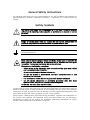
Safety Symbols
This symbol may appear on the equipment or in the text. It indicates potential
safety hazards regarding product operation or maintenance to operator or service
personnel.
Warning
Danger of electric shock! Avoid any contact with the marked surface while the
product is energized or connected to outdoor telecommunication lines.
Protective ground: the marked lug or terminal should be connected to the building
protective ground bus.
Warning
Some products may be equipped with a laser diode. In such cases, a label with the
laser class and other warnings as applicable will be attached near the optical
transmitter. The laser warning symbol may be also attached.
Please observe the following precautions:
•
Before turning on the equipment, make sure that the fiber optic cable is intact
and is connected to the transmitter.
•
Do not attempt to adjust the laser drive current.
•
Do not use broken or unterminated fiber-optic cables/connectors or look
straight at the laser beam.
•
The use of optical devices with the equipment will increase eye hazard.
•
Use of controls, adjustments or performing procedures other than those
specified herein, may result in hazardous radiation exposure.
ATTENTION: The laser beam may be invisible!
In some cases, the users may insert their own SFP laser transceivers into the product. Users are
alerted that RAD cannot be held responsible for any damage that may result if non-compliant
transceivers are used. In particular, users are warned to use only agency approved products that
comply with the local laser safety regulations for Class 1 laser products.
Always observe standard safety precautions during installation, operation and maintenance of
this product. Only qualified and authorized service personnel should carry out adjustment,
maintenance or repairs to this product. No installation, adjustment, maintenance or repairs
should be performed by either the operator or the user.
Handling Energized Products
General Safety Practices
Do not touch or tamper with the power supply when the power cord is connected. Line voltages
may be present inside certain products even when the power switch (if installed) is in the OFF
position or a fuse is blown. For DC-powered products, although the voltages levels are usually
not hazardous, energy hazards may still exist.
Before working on equipment connected to power lines or telecommunication lines, remove
jewelry or any other metallic object that may come into contact with energized parts.
Unless otherwise specified, all products are intended to be grounded during normal use.
Grounding is provided by connecting the mains plug to a wall socket with a protective ground
terminal. If a ground lug is provided on the product, it should be connected to the protective
ground at all times, by a wire with a diameter of 18 AWG or wider. Rack-mounted equipment
should be mounted only in grounded racks and cabinets.
Always make the ground connection first and disconnect it last. Do not connect
telecommunication cables to ungrounded equipment. Make sure that all other cables are
disconnected before disconnecting the ground.
Connecting AC Mains
Make sure that the electrical installation complies with local codes.
Always connect the AC plug to a wall socket with a protective ground.
The maximum permissible current capability of the branch distribution circuit that supplies power
to the product is 16A. The circuit breaker in the building installation should have high breaking
capacity and must operate at short-circuit current exceeding 35A.
Always connect the power cord first to the equipment and then to the wall socket. If a power
switch is provided in the equipment, set it to the OFF position. If the power cord cannot be
readily disconnected in case of emergency, make sure that a readily accessible circuit breaker or
emergency switch is installed in the building installation.
In cases when the power distribution system is IT type, the switch must disconnect both poles
simultaneously.
Connecting DC Power
Unless otherwise specified in the manual, the DC input to the equipment is floating in reference
to the ground. Any single pole can be externally grounded.
Due to the high current capability of DC power systems, care should be taken when connecting
the DC supply to avoid short-circuits and fire hazards.
DC units should be installed in a restricted access area, i.e. an area where access is authorized
only to qualified service and maintenance personnel.
Make sure that the DC power supply is electrically isolated from any AC source and that the
installation complies with the local codes.
The maximum permissible current capability of the branch distribution circuit that supplies power
to the product is 16A. The circuit breaker in the building installation should have high breaking
capacity and must operate at short-circuit current exceeding 35A.
Before connecting the DC supply wires, ensure that power is removed from the DC circuit. Locate
the circuit breaker of the panel board that services the equipment and switch it to the OFF
position. When connecting the DC supply wires, first connect the ground wire to the
corresponding terminal, then the positive pole and last the negative pole. Switch the circuit
breaker back to the ON position.
A readily accessible disconnect device that is suitably rated and approved should be incorporated
in the building installation.
If the DC power supply is floating, the switch must disconnect both poles simultaneously.
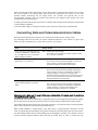
Connecting Data and Telecommunications Cables
Data and telecommunication interfaces are classified according to their safety status.
The following table lists the status of several standard interfaces. If the status of a given port
differs from the standard one, a notice will be given in the manual.
Ports
Safety Status
V.11, V.28, V.35, V.36, RS-530, X.21,
10 BaseT, 100 BaseT, Unbalanced E1,
E2, E3, STM, DS-2, DS-3, S-Interface
ISDN, Analog voice E&M
SELV
xDSL (without feeding voltage),
Balanced E1, T1, Sub E1/T1
TNV-1 Telecommunication Network Voltage-1:
Ports whose normal operating voltage is within the
limits of SELV, on which overvoltages from
telecommunications networks are possible.
FXS (Foreign Exchange Subscriber)
TNV-2 Telecommunication Network Voltage-2:
Ports whose normal operating voltage exceeds the
limits of SELV (usually up to 120 VDC or telephone
ringing voltages), on which overvoltages from
telecommunication networks are not possible. These
ports are not permitted to be directly connected to
external telephone and data lines.
FXO (Foreign Exchange Office), xDSL
(with feeding voltage), U-Interface
ISDN
TNV-3 Telecommunication Network Voltage-3:
Ports whose normal operating voltage exceeds the
limits of SELV (usually up to 120 VDC or telephone
ringing voltages), on which overvoltages from
telecommunication networks are possible.
Safety Extra Low Voltage:
Ports which do not present a safety hazard. Usually
up to 30 VAC or 60 VDC.
Always connect a given port to a port of the same safety status. If in doubt, seek the assistance
of a qualified safety engineer.
Always make sure that the equipment is grounded before connecting telecommunication cables.
Do not disconnect the ground connection before disconnecting all telecommunications cables.
Some SELV and non-SELV circuits use the same connectors. Use caution when connecting cables.
Extra caution should be exercised during thunderstorms.
When using shielded or coaxial cables, verify that there is a good ground connection at both
ends. The grounding and bonding of the ground connections should comply with the local codes.
The telecommunication wiring in the building may be damaged or present a fire hazard in case of
contact between exposed external wires and the AC power lines. In order to reduce the risk,
there are restrictions on the diameter of wires in the telecom cables, between the equipment
and the mating connectors.
Caution
To reduce the risk of fire, use only No. 26 AWG or larger telecommunication line
cords.
Attention
Pour réduire les risques s’incendie, utiliser seulement des conducteurs de
télécommunications 26 AWG ou de section supérieure.
Some ports are suitable for connection to intra-building or non-exposed wiring or cabling only. In
such cases, a notice will be given in the installation instructions.
Do not attempt to tamper with any carrier-provided equipment or connection hardware.
Electromagnetic Compatibility (EMC)
The equipment is designed and approved to comply with the electromagnetic regulations of
major regulatory bodies. The following instructions may enhance the performance of the
equipment and will provide better protection against excessive emission and better immunity
against disturbances.
A good ground connection is essential. When installing the equipment in a rack, make sure to
remove all traces of paint from the mounting points. Use suitable lock-washers and torque. If an
external grounding lug is provided, connect it to the ground bus using braided wire as short as
possible.
The equipment is designed to comply with EMC requirements when connecting it with unshielded
twisted pair (UTP) cables. However, the use of shielded wires is always recommended, especially
for high-rate data. In some cases, when unshielded wires are used, ferrite cores should be
installed on certain cables. In such cases, special instructions are provided in the manual.
Disconnect all wires which are not in permanent use, such as cables used for one-time
configuration.
The compliance of the equipment with the regulations for conducted emission on the data lines
is dependent on the cable quality. The emission is tested for UTP with 80 dB longitudinal
conversion loss (LCL).
Unless otherwise specified or described in the manual, TNV-1 and TNV-3 ports provide secondary
protection against surges on the data lines. Primary protectors should be provided in the building
installation.
The equipment is designed to provide adequate protection against electro-static discharge (ESD).
However, it is good working practice to use caution when connecting cables terminated with
plastic connectors (without a grounded metal hood, such as flat cables) to sensitive data lines.
Before connecting such cables, discharge yourself by touching ground or wear an ESD preventive
wrist strap.
FCC-15 User Information
This equipment has been tested and found to comply with the limits of the Class A digital device,
pursuant to Part 15 of the FCC rules. These limits are designed to provide reasonable protection
against harmful interference when the equipment is operated in a commercial environment. This
equipment generates, uses and can radiate radio frequency energy and, if not installed and used
in accordance with the Installation and Operation manual, may cause harmful interference to the
radio communications. Operation of this equipment in a residential area is likely to cause harmful
interference in which case the user will be required to correct the interference at his own
expense.
Canadian Emission Requirements
This Class A digital apparatus meets all the requirements of the Canadian Interference-Causing
Equipment Regulation.
Cet appareil numérique de la classe A respecte toutes les exigences du Règlement sur le matériel
brouilleur du Canada.
Warning per EN 55022 (CISPR-22)
Warning
Avertissement
Achtung
This is a class A product. In a domestic environment, this product may cause radio
interference, in which case the user will be required to take adequate measures.
Cet appareil est un appareil de Classe A. Dans un environnement résidentiel, cet
appareil peut provoquer des brouillages radioélectriques. Dans ces cas, il peut être
demandé à l’utilisateur de prendre les mesures appropriées.
Das vorliegende Gerät fällt unter die Funkstörgrenzwertklasse A. In Wohngebieten
können beim Betrieb dieses Gerätes Rundfunkströrungen auftreten, für deren
Behebung der Benutzer verantwortlich ist.
Français
Mise au rebut du produit
Afin de faciliter la réutilisation, le recyclage ainsi que d'autres formes de
récupération d'équipement mis au rebut dans le cadre de la protection de
l'environnement, il est demandé au propriétaire de ce produit RAD de ne pas
mettre ce dernier au rebut en tant que déchet municipal non trié, une fois
que le produit est arrivé en fin de cycle de vie. Le client devrait proposer des
solutions de réutilisation, de recyclage ou toute autre forme de mise au rebut
de cette unité dans un esprit de protection de l'environnement, lorsqu'il aura
fini de l'utiliser.
Instructions générales de sécurité
Les instructions suivantes servent de guide général d'installation et d'opération sécurisées des
produits de télécommunications. Des instructions supplémentaires sont éventuellement
indiquées dans le manuel.
Symboles de sécurité
Ce symbole peut apparaitre sur l'équipement ou dans le texte. Il indique des risques
potentiels de sécurité pour l'opérateur ou le personnel de service, quant à
l'opération du produit ou à sa maintenance.
Avertissement
Danger de choc électrique ! Evitez tout contact avec la surface marquée tant que le
produit est sous tension ou connecté à des lignes externes de télécommunications.
Mise à la terre de protection : la cosse ou la borne marquée devrait être connectée
à la prise de terre de protection du bâtiment.
•
Avant la mise en marche de l'équipement, assurez-vous que le câble de fibre
optique est intact et qu'il est connecté au transmetteur.
•
Ne tentez pas d'ajuster le courant de la commande laser.
•
N'utilisez pas des câbles ou connecteurs de fibre optique cassés ou sans
terminaison et n'observez pas directement un rayon laser.
•
L'usage de périphériques optiques avec l'équipement augmentera le risque pour
les yeux.
•
L'usage de contrôles, ajustages ou procédures autres que celles spécifiées ici
pourrait résulter en une dangereuse exposition aux radiations.
ATTENTION : Le rayon laser peut être invisible !
Les utilisateurs pourront, dans certains cas, insérer leurs propres émetteurs-récepteurs Laser SFP
dans le produit. Les utilisateurs sont avertis que RAD ne pourra pas être tenue responsable de
tout dommage pouvant résulter de l'utilisation d'émetteurs-récepteurs non conformes. Plus
particulièrement, les utilisateurs sont avertis de n'utiliser que des produits approuvés par
l'agence et conformes à la réglementation locale de sécurité laser pour les produits laser de
classe 1.
Respectez toujours les précautions standards de sécurité durant l'installation, l'opération et la
maintenance de ce produit. Seul le personnel de service qualifié et autorisé devrait effectuer
l'ajustage, la maintenance ou les réparations de ce produit. Aucune opération d'installation,
d'ajustage, de maintenance ou de réparation ne devrait être effectuée par l'opérateur ou
l'utilisateur.
Manipuler des produits sous tension
Règles générales de sécurité
Ne pas toucher ou altérer l'alimentation en courant lorsque le câble d'alimentation est branché.
Des tensions de lignes peuvent être présentes dans certains produits, même lorsque le
commutateur (s'il est installé) est en position OFF ou si le fusible est rompu. Pour les produits
alimentés par CC, les niveaux de tension ne sont généralement pas dangereux mais des risques
de courant peuvent toujours exister.
Avant de travailler sur un équipement connecté aux lignes de tension ou de télécommunications,
retirez vos bijoux ou tout autre objet métallique pouvant venir en contact avec les pièces sous
tension.
Sauf s'il en est autrement indiqué, tous les produits sont destinés à être mis à la terre durant
l'usage normal. La mise à la terre est fournie par la connexion de la fiche principale à une prise
murale équipée d'une borne protectrice de mise à la terre. Si une cosse de mise à la terre est
fournie avec le produit, elle devrait être connectée à tout moment à une mise à la terre de
protection par un conducteur de diamètre 18 AWG ou plus. L'équipement monté en châssis ne
devrait être monté que sur des châssis et dans des armoires mises à la terre.
Branchez toujours la mise à la terre en premier et débranchez-la en dernier. Ne branchez pas des
câbles de télécommunications à un équipement qui n'est pas mis à la terre. Assurez-vous que
tous les autres câbles sont débranchés avant de déconnecter la mise à la terre.
Français
Certains produits peuvent être équipés d'une diode laser. Dans de tels cas, une
étiquette indiquant la classe laser ainsi que d'autres avertissements, le cas échéant,
sera jointe près du transmetteur optique. Le symbole d'avertissement laser peut
aussi être joint.
Avertissement
Veuillez observer les précautions suivantes :
Français
Connexion au courant du secteur
Assurez-vous que l'installation électrique est conforme à la réglementation locale.
Branchez toujours la fiche de secteur à une prise murale équipée d'une borne protectrice de mise
à la terre.
La capacité maximale permissible en courant du circuit de distribution de la connexion alimentant
le produit est de 16A. Le coupe-circuit dans l'installation du bâtiment devrait avoir une capacité
élevée de rupture et devrait fonctionner sur courant de court-circuit dépassant 35A.
Branchez toujours le câble d'alimentation en premier à l'équipement puis à la prise murale. Si un
commutateur est fourni avec l'équipement, fixez-le en position OFF. Si le câble d'alimentation ne
peut pas être facilement débranché en cas d'urgence, assurez-vous qu'un coupe-circuit ou un
disjoncteur d'urgence facilement accessible est installé dans l'installation du bâtiment.
Le disjoncteur devrait déconnecter simultanément les deux pôles si le système de distribution de
courant est de type IT.
Connexion d'alimentation CC
Sauf s'il en est autrement spécifié dans le manuel, l'entrée CC de l'équipement est flottante par
rapport à la mise à la terre. Tout pôle doit être mis à la terre en externe.
A cause de la capacité de courant des systèmes à alimentation CC, des précautions devraient
être prises lors de la connexion de l'alimentation CC pour éviter des courts-circuits et des risques
d'incendie.
Les unités CC devraient être installées dans une zone à accès restreint, une zone où l'accès n'est
autorisé qu'au personnel qualifié de service et de maintenance.
Assurez-vous que l'alimentation CC est isolée de toute source de courant CA (secteur) et que
l'installation est conforme à la réglementation locale.
La capacité maximale permissible en courant du circuit de distribution de la connexion alimentant
le produit est de 16A. Le coupe-circuit dans l'installation du bâtiment devrait avoir une capacité
élevée de rupture et devrait fonctionner sur courant de court-circuit dépassant 35A.
Avant la connexion des câbles d'alimentation en courant CC, assurez-vous que le circuit CC n'est
pas sous tension. Localisez le coupe-circuit dans le tableau desservant l'équipement et fixez-le
en position OFF. Lors de la connexion de câbles d'alimentation CC, connectez d'abord le
conducteur de mise à la terre à la borne correspondante, puis le pôle positif et en dernier, le
pôle négatif. Remettez le coupe-circuit en position ON.
Un disjoncteur facilement accessible, adapté et approuvé devrait être intégré à l'installation du
bâtiment.
Le disjoncteur devrait déconnecter simultanément les deux pôles si l'alimentation en courant CC
est flottante.
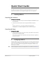
Quick Start Guide
The ASMi-54 should be installed by an experienced technician only. If you are
familiar with the ASMi-54, use this guide to prepare the unit for operation.
1.
Installing ASMi-54
Connecting the Interfaces
To connect the interfaces:
1. Connect the user LAN to the RJ-45 connector designated 10/100BaseT (up to
four connectors).
2. Connect the control terminal to the front panel CONTROL connector.
or
Connect a Telnet host, a PC running a Web browsing application
(ConfiguRAD), or an SNMP management station to the Ethernet port.
Connecting the Power
To connect the power:
•
Connect the power cable to the power socket on the ASMi-54 rear panel and
the other end to the power outlet.
The unit has no power switch. Operation starts when the power is applied to
the power connector.
2.
Configuring ASMi-54
Configure ASMi-54 to the desired operation mode via an ASCII terminal connected
to the rear panel CONTROL port. After configuring, you can manage the unit over
Telnet, a PC running a Web browsing application (ConfiguRAD) or SNMP via the
Ethernet port or inband.
Note
ASMi-54 Ver. 1.0
Remote management requires the configuration of an IP address (see Chapter 4).
Configuring ASMi-54
1
Quick Start Guide
Installation and Operation Manual
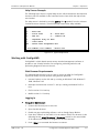
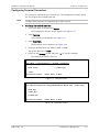
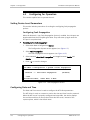
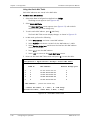
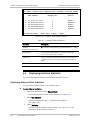
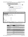
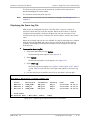
Starting a Terminal Session
To start a terminal session:
1. Turn on the control terminal PC and set its default port parameters to 9,600
bps, 8 bits/character, 1 stop bit, no parity.
2. Set the terminal emulator to ANSI VT100 emulation (for optimal view of
system menus).
3. Set the terminal screen to show 132 characters.
4. Enter your user name and password and proceed with the management
session.
Note
The default user name is su, and the default password is 1234.
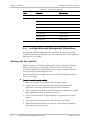
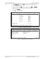
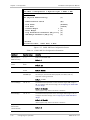
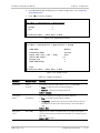
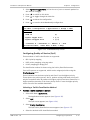
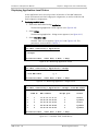
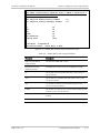
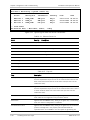
Configuring ASMi-54 SHDSL Ports
When working with two devices back to back, one device should be configured as
CO (Central Office) and the other device as CPE (Customer Premise Equipment).
The factory default setting is CPE, so only one device needs to be changed.
To configure ASMi-54 SHDSL ports:
•
Set one device to CO (internal clock) and leave the other as CPE (receive
clock).
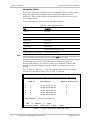
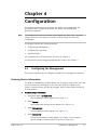
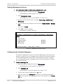
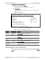
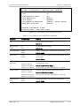
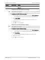
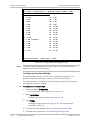
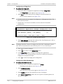
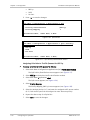
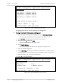
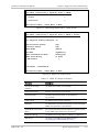
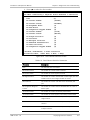
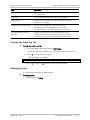
Configuring ASMi-54 for Management
To configure ASMi-54 for management:
1. From the Host menu, select Main>Configuration>System>Management>Host,
and configure the following parameters:
Host IP address
Host IP mask
Default gateway.
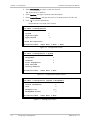
2. From the Encapsulation menu, select
Main>Configuration>System>Management>Host>Encapsulation, and
configure Host tagging (untagged/tagged). Note that selecting the tagged
option displays the following additional parameters that need to be defined:
Host VLAN ID
Host VLAN Priority
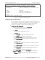
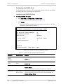
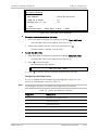
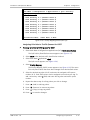
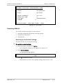
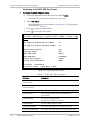
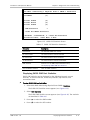
To configure the manager IP addresses:
•
2
From the Manager List menu, select
Main>Configuration>System>Management>Managers List, and enter the
manager IP address(es).
Configuring ASMi-54
ASMi-54 Ver. 1.0
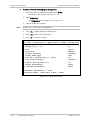
Contents
Chapter 1. Introduction
1.1
1.2
1.3
1.4
Overview....................................................................................................................1-1
Versions .................................................................................................................1-1
Applications............................................................................................................1-2
Main Features.........................................................................................................1-2
Physical Description ...................................................................................................1-5
Functional Description................................................................................................1-5
Interfaces ...............................................................................................................1-5
Ethernet Access (Bridge).........................................................................................1-6
Quality of Service..................................................................................................1-10
Management ........................................................................................................1-11
Security ................................................................................................................1-12
Statistics ..............................................................................................................1-12
Event Log File .......................................................................................................1-12
Diagnostics and Troubleshooting ..........................................................................1-12
Technical Specifications............................................................................................1-12
Chapter 2. Installation and Setup
2.1
2.2
2.3
2.4
2.5
2.6
2.7
Introduction...............................................................................................................2-1
Site Requirements and Prerequisites ..........................................................................2-1
Package Contents ......................................................................................................2-2
Equipment Needed.....................................................................................................2-2
Hand Tools and Kits................................................................................................2-2
Power Cable............................................................................................................2-2
Cable and Connectors .............................................................................................2-2
Mounting the Unit......................................................................................................2-3
Connecting the Cables................................................................................................2-3
Connecting to the Ethernet Equipment....................................................................2-3
Connecting to the SHDSL Equipment .......................................................................2-4
Connecting to an ASCII Terminal ..............................................................................2-4
Connecting to Power..................................................................................................2-4
Connecting AC Power..............................................................................................2-4
Connecting DC Power..............................................................................................2-4
Chapter 3. Operation
3.1
3.2
3.3
3.4
3.5
Turning On the Unit ...................................................................................................3-1
Indicators ..................................................................................................................3-1
Front Panel Indicators .............................................................................................3-1
Rear Panel Indicators ..............................................................................................3-2
Default Settings .........................................................................................................3-3
Configuration and Management Alternatives ..............................................................3-6
Working with the Terminal ......................................................................................3-6
Working with ConfiguRAD .......................................................................................3-9
Turning Off the Unit.................................................................................................3-13
Chapter 4. Configuration
4.1
Configuring for Management ......................................................................................4-1
ASMi-54 Ver. 1.0
i
Table of Contents
4.2
4.3
Installation and Operation Manual
Entering Device Information....................................................................................4-1
Configuring IP Host Parameters...............................................................................4-3
Configuring Terminal Parameters.............................................................................4-5
Setting Management Access ...................................................................................4-6
Configuring the Network Managers .........................................................................4-6
Configuring for Operation ..........................................................................................4-8
Setting Device-Level Parameters .............................................................................4-8
Configuring Date and Time......................................................................................4-8
Configuring Physical-Level Port Parameters .............................................................4-9
Additional Tasks.......................................................................................................4-27
Displaying the Inventory .......................................................................................4-27
Changing User Name and Password.......................................................................4-28
Transferring Software and Configuration Files .......................................................4-29
Resetting ASMi-54 ................................................................................................4-31
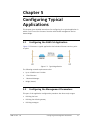
Chapter 5. Configuring Typical Applications
5.1
5.2
5.3
5.4
Configuring the ASMi-54 Application...........................................................................5-1
Configuring the Management Parameters ...................................................................5-1
Defining the Host ...................................................................................................5-2
Defining the Default Gateway .................................................................................5-2
Defining Managers..................................................................................................5-2
Configuring SHDSL Physical Layer ...............................................................................5-3
Configuring the Bridge ...............................................................................................5-3
Defining the Bridge.................................................................................................5-4
Defining VLANs .......................................................................................................5-4
Defining Bridge Ports ..............................................................................................5-4
Chapter 6. Diagnostics and Troubleshooting
6.1
6.2
6.3
6.4
6.5
6.6
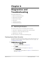
Monitoring Performance.............................................................................................6-1
Displaying System Status Information .....................................................................6-1
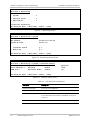
Displaying the Physical Port Status..........................................................................6-3
Displaying Application-Level Status .........................................................................6-7
Displaying Interface Statistics.....................................................................................6-8
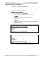
Displaying Ethernet Port Statistics...........................................................................6-8
Clearing Ethernet Port Statistics ............................................................................6-10
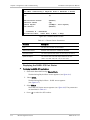
Displaying SHDSL Port Statistics ............................................................................6-10
Clearing the SHDSL Port Statistics .........................................................................6-18
Handling Alarms and Traps .......................................................................................6-18
Displaying the Event Log File.................................................................................6-19
Clearing the Event Log File ....................................................................................6-21
Debugging Errors ..................................................................................................6-21
Troubleshooting.......................................................................................................6-22
Testing the Unit .......................................................................................................6-23
Running a Ping Test ..............................................................................................6-23
Tracing the Route .................................................................................................6-24
Technical Support ....................................................................................................6-24
Appendix A. Pinouts
Appendix B. Boot Sequence and Downloading Software
ii
ASMi-54 Ver. 1.0
Chapter 1
Introduction
1.1
Overview
ASMi-54 is a standalone SHDSL modem with G.SHDSL.bis and EFM (Ethernet in
the First Mile) technologies that provides up to 22.8 Mbps of bandwidth.
ASMi-54 is a dedicated managed SHDSL modem that supports multiple data rates
and operates in full duplex mode over 2-wire, 4-wire, or 8-wire lines.
ASMi-54 uses TC-PAM 16 or TC-PAM 32 line coding SHDSL technology to transmit
up to 5.7 Mbps of bandwidth, point-to-point, over each copper pair with EFM
bonding. This enables each link to synchronize at a different rate and extends the
range of digital interfaces. This device offers longer distances and variable data
rates up to 5.7 Mbps over 2-wire, 11.4 Mbps over 4-wire, and 22.8 Mbps over
8-wire.
EFM bonding ensures that a failure or addition of a link does not drop the traffic
being transmitted over the other wires in the group, nor is the capacity of the
group decreased when a new link is added at lower rate. This is particularly
relevant for operators offering Ethernet services in the First Mile where fiber is
absent or impractical to install.
The ASMi-54 G.SHDSL.bis modem implements the IEEE's 802.1Q standards to
provide VLAN-tagging with four levels of prioritization, enabling carriers to offer
differentiated Ethernet services. VLAN tagging can also be employed to separate
traffic, ensuring transparency of the customer traffic and bolstering security of
management traffic.
ASMi-54 provides monitoring, control, and diagnostics of a local unit via a
supervisory port (Control).
Versions
Line Interface
ASMi-54 supports SHDSL twisted pair wire-line connection and can be ordered
with one of the following pairs of wires:
•
One pair (2-wire)
•
Two pairs (4-wire)
•
Four pairs (8-wire)
Unit Enclosure
ASMi-54 is available in a plastic or metal enclosure.
ASMi-54 Ver. 1.0
Overview
1-1
Chapter 1 Introduction
Installation and Operation Manual
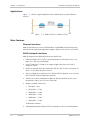
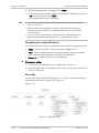
Applications
Figure
1-1 shows a typical application that includes point-to-point Ethernet
services.
Figure
1-1. ASMi-54 (ETH) vs. ASMi-54 (ETH)
Main Features
Ethernet Interfaces
ASMi-54 provides one or four half/full duplex, 10/100 Mbps Fast Ethernet ports,
with flow control and autonegotiation support. All ports are used for user traffic.
SHDSL Network Interfaces
ASMi-54 supports the following features per SHDSL line:
•
Enhanced SHDSL ITU-T G.991.2 recommendation for user data rates n × 64
kbps (n = 1..89) up to 5696 kpbs
•
Uses TC-PAM 16 or TC-PAM 32 to support higher data rates for G.991.2
Annexes F and G
•
SHDSL twisted pair wire-line connection with one pair (2-wires), two pairs (4wires), or four pairs (8-wires) of wires
•
Can be configured to operate as a CO (Central Office) product or as a remote
CPE (Customer Premise Equipment) product
•
The line rate can be configured to adapt to the line condition (noise, loop
attenuation, and so on) or set to a fixed rate
•
Range* (26 AWG, noise-free)
192 kpbs – 8 km
1536 kpbs – 5.7 km
2048 kpbs – 5.1 km
4096 kpbs – 3.9 km
4608 kpbs – 3.5 km
5696 kpbs – 2.9 km.
*Preliminary estimate
•
1-2
Overview
Embedded Operations Channel (EOC) according to G.991.2 recommendation.
ASMi-54 Ver. 1.0
Installation and Operation Manual
Chapter 1 Introduction
WAN Protocol
ASMi-54 supports EFM.
PCS and PME
ASMi-54 follows EFM naming conventions:
•
DSL pairs are called PME (Physical Medium Entity)
•
A group of pairs (up to four in ASMi-54) is called PCS (Physical Coding
Sublayer).
The total bandwidth of the PCS port (the WAN direction) equals the sum of the
bandwidths of its underlying PME lines. The maximum rate of a single PME is
5696000, and the maximum bandwidth of the PCS port is 22784000 bps
(4 × 5696000).
Bridging
ASMi-54 provides a bridging function between the various bridge ports:
•
Fast Ethernet ports
•
Internal host.
The internal bridge operates in VLAN-Unaware or VLAN-Aware modes.
The VLAN-Aware bridge mode allows the user to create a subgroup of bridge
ports within the bridge. Each subgroup is associated with a unique VLAN Identifier
(VID). Frames can be forwarded only between bridge ports that are members of
the same VLAN, enabling a total separation between different VLAN users within
the same bridge.
In VLAN-Unaware bridge mode, the bridge ignores VLAN tags and forwards
frames only according to their source and destination MAC addresses.
ASMi-54 supports QoS mapping from bridge ports and Ethernet VLAN priority,
VLAN stacking/stripping per bridge port, ingress and egress.
Quality of Service
ASMi-54 supports Quality of Service (QoS) on DSL egress direction. Classification
is according to VLAN priority (802.1p), DSCP (bits 0-5 in IP TOS byte) and port
based. Mapping classification results into four transmit priority queues with strict
priority.
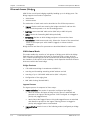
Fault Propagation
When the Network > User Fault Propagation feature is enabled, the LAN ports are
deactivated when the PCS uplink goes down. They will come up again once the
PCS port is resynchronized.
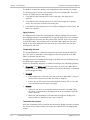
Management
ASMi-54 can be managed via:
ASMi-54 Ver. 1.0
•
RS-232 craft port
•
An inband management channel via Ethernet or PCS port (with or without
dedicated VLAN encapsulation).
Overview
1-3
Chapter 1 Introduction
Installation and Operation Manual
Access to the ASMi-54 software can be limited to the ASCII terminal and
ConfiguRAD management by disabling the Telnet access.
The following functions are supported by the internal management software:
•
Local terminal, Telnet server, SNMP (V1), WEB server (ConfiguRAD)
ConfiguRAD is RAD’s Web-based element management system for remote
device configuration and maintenance. ConfiguRAD is embedded in the unit
and can be accessed from any standard Web browser.
•
RADview-Lite
RADview-Lite is RAD’s SNMP-based element management software, providing
SNMP traps, status polling, and configuration download. Remote element
management is available in either through the ConfiguRAD or Telnet.
•
Inband and out-of-band management with/without dedicated management
VLAN
•
Ping and Trace Routes
•
Remote software and configuration download / upload via TFTP
•
DHCP client to obtain IP address, mask and default gateway
•
Viewing system information
•
Modifying configuration and mode of operation, including setting system
default values and resetting the unit
•
Monitoring performance
•
Initiating connectivity tests
•
Upgrading software.
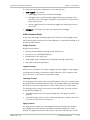
Timing
ASMi-54 operates with the following clock sources:
•
Internal clock source, derived from the modem as a CO unit
•
Received clock source, derived from the DSL line on a CPE unit.
Diagnostics
Real-time alarms provide information on the system status, indicating
management failure, synchronization loss, and other conditions.
ASMi-54 also supports performance monitoring.
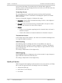
Event Log File
The Event Log file includes entries at the system and Ethernet levels.
Statistics
ASMi-54 provides statistics and counter capabilities in the physical Ethernet and
SHDSL level.
1-4
Overview
ASMi-54 Ver. 1.0
Installation and Operation Manual
1.2
Chapter 1 Introduction
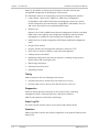
Physical Description
ASMi-54 is a 1U high standalone device in a plastic or metal enclosure.
Figure 1-2 shows a three-dimensional view of the ASMi-54 unit with Ethernet
and SHDSL interfaces. The front and rear panels are shown in Chapter 3.
Figure
1-2. ASMi-54 Front View (Plastic Enclosure)
The LEDs are located on the front panel. The interfaces and connectors are
located on the rear panel. For more information, see Chapter 2.
ASMi-54 can be powered by wide-range AC/DC (100-240 VAC, -48/60 VDC
nominal).
1.3
Functional Description
This section describes the major functional features of ASMi-54.
Interfaces
Ethernet Interface
The Ethernet physical interface is 10/100BaseT. The interface supports
autonegotiation.
WAN Interface
The SHDSL interface supports ITU-T G.991.2, ETSI 101524, and IEEE EFM
(IEEE802.3ah) standards for SHDSL.
Control Interface
The Control port connects directly to an ASCII terminal for managing the ASMi-54.
ASMi-54 Ver. 1.0
Functional Description
1-5
Chapter 1 Introduction
Installation and Operation Manual
Ethernet Access (Bridge)
ASMi-54 has a multi-port bridging capability handling up to six bridge ports. The
Bridge supports two modes of operation:
•
VLAN-Aware
•
VLAN-Unaware.
The mechanism of each mode can be described as five different processes:
•
Ingress: Checks each frame entering the bridge to decide if and how this
frame should be passed on to the forwarding process
•
Learning: Learns new MAC table entries (MAC only or MAC VID pairs)
•
Aging: Checks the forwarding MAC table periodically
•
Forwarding: Decides to which bridge port/ports to forward the frame
•
Transmission (VLAN-Aware mode only): Selects the format of the transmitted
frame at the output port: with VLAN ID (tagged) or without VLAN ID
(untagged).
Bridge features and these five processes are described below for each mode.
VLAN-Aware Mode
This mode enables the creation of sub-groups of bridge ports within the bridge.
Each sub-group is defined per VLAN and is associated with a unique VLAN ID
(VID). Frames containing a VID can be forwarded only between bridge ports that
are members of this specific VLAN, enabling a total separation between different
VLAN users within the same bridge.
Bridge Features
•
Full VLAN-Aware bridge in accordance with 802.1Q
•
Learning and forwarding according to MAC address and VID
•
Learning of up to 1,024 MAC table entries (MAC + VID pairs)
•
Configuration of the aging time
•
MAC table viewing (learned MACs).
Ingress Process
The ingress process is composed of three steps:
•
Frame Admission: Two modes of operation (configured per bridge):
Admit All Frames: All frames arriving from the port are admitted and
proceed to the ingress filtering process. PVID is assigned to untagged or
priority only tagged frames.
Admit Only VLAN Tagged Frames: Only VLAN tagged frames are admitted
and allowed to proceed to the ingress filtering process. Untagged or
priority-only tagged frames are discarded.
•
1-6
Ingress Filtering: Works in one of the following modes (configured per bridge
port):
Functional Description
ASMi-54 Ver. 1.0
Installation and Operation Manual
Chapter 1 Introduction
Enable: Performs ingress filtering according to VIDs. Only frames that
share a VID assigned to this bridge port are admitted
Disable: All frames are forwarded.
Only admitted frames that pass filtering are submitted to learning and
forwarding processes.
•
PVID Assignment: Is per bridge port configuration:
In VLAN-Aware mode, each received frame entering the bridge is
associated with a single VID. In case the received frame does not contain
a VLAN ID (untagged or priority only tagged frames), a specific PVID is
assigned to these frames before they pass to the forwarding process.
Accordingly, the untagged/priority tagged frames that have passed the
admission/ingress filtering, are tagged with PVID and proceed to the
forwarding process. Tagged frames will be double tagged with the PVID
only if Tag Stacking is enabled.
For untagged frames that were tagged during this process to VID=PVID,
the priority tag is assigned at the VLAN priority field, according to the
default priority configuration.
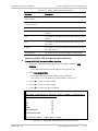
Table
1-1 summarizes the behavior of the ingress process:
Table
1-1. Ingress Process
Frame Admission
Mode
Ingress
Filtering Mode
Bridge Behavior
Admit all frames
Enable
VLAN tagged frames with a VID (or PVID for
untagged/priority tagged frames) that do not
include the bridge port in their VLAN member
set, are dropped.
Disable
All frames pass.
Enable
VLAN tagged frames with a VID that do not
include the bridge port in their member set are
dropped. Untagged/priority-only tagged frames
are dropped.
Disable
All VLAN tagged frames pass.
Untagged/priority-only tagged frames are
dropped.
Admit VLAN tagged
frames
Frames that pass this stage are submitted to the forwarding and learning
processes.
Learning Process
The learning process observes the source MAC address (SA) and the VID of the
received frame, and updates the forwarding database with the MAC VID pair and
with the bridge port that the frame was received from. The Forwarding Data Base
(FDB) is also referred to as a MAC table.
Entries in the MAC table can be dynamic (inserted by the learning process) or
static (inserted by configuration). A dynamic entry has an aging time associated
with it.
ASMi-54 Ver. 1.0
Functional Description
1-7
Chapter 1 Introduction
Installation and Operation Manual
The ASMi-54 VLAN-Aware bridge is an Independent VLAN Learning (IVL) bridge.
The learning process inserts a new dynamic entry into the MAC table. This entry
consists of a MAC-VID pair and bridge port.
•
If the MAC-VID pair already exists for the same port, the aging time is
updated
•
If the MAC-VID pair already exists but for a different bridge port (dynamic
entry), the new entry overrides the existing one
•
If the MAC-VID pair already exists for a different bridge port (static entry), the
static entry prevails.
Aging Process
The aging process checks the forwarding MAC table periodically. Each dynamic
entry-aging period that has exceeded the configured Aging Time Limit is deleted.
The aging period represents the time passed since the last frame for this entry
entered the bridge. The periodic check of the MAC table (aging time intervals)
results in the actual aging time that can reach up to twice the value that was
configured by the user.
Forwarding Process
The forwarding process is performed based on the frame destination MAC VID
pair. The frame is forwarded to the bridge port that was specified in the MAC
table for this MAC VID pair entry.
Untagged frames are forwarded according to the PVID that was attached to that
frame during the ingress process.
Frames are forwarded, dropped, or flooded according to the following guidelines:
•
Forwarded: If the bridge port of the pair entry (DA, VID) in the MAC table is
both an active bridge port and a member of the VLAN, the frame is forwarded
to that bridge port only.
•
Dropped:
If the bridge port for the pair entry (DA, VID) in the MAC table is the port
on which the frame was received, the frame is dropped.
If there are no active ports associated with the frame’s VID, or if the VID
is not defined at all, the frame is dropped.
•
Flooded:
If the pair (DA, VID) is not learned and does not exist in the MAC table,
the frame is transmitted to all bridge ports that are associated with the
frame’s VLAN ID.
Multicasts and broadcasts are flooded only through the bridge ports
whose VLAN ID is identical to the frame’s VLAN ID.
Transmission Process
After the forwarding process identifies the destination bridge port/ports to which
the frames must be transmitted, the frames are transmitted in the appropriate
format.
1-8
Functional Description
ASMi-54 Ver. 1.0
Installation and Operation Manual
Chapter 1 Introduction
The frame format can be configured for each VLAN and port:
•
VLAN-tagged: In this mode:
VLAN-tagged frames are transmitted unchanged.
Untagged frames are transmitted tagged with priority according to the
default priority of the ingress bridge port, and VID=PVID of the port from
which they entered.
Priority-tagged frames are transmitted tagged with original priority and
VID = PVID.
•
Untagged: In this mode, all frames are transmitted as untagged.
VLAN-Unaware Mode
In this mode the bridge forwarding ignores the VLAN ID of VLAN-tagged frames.
Each Ethernet packet received from each bridge port is forwarded according to its
destination MAC address.
Bridge Features
Bridge features include:
•
Learning and forwarding according to MAC address only
•
Learning of up to 2048 MAC addresses
•
Configuration of the aging time
•
VLAN tagged frames transparency (forwarding according to MAC only)
•
MAC table viewing (learned MACs)
Ingress Process
All frames are accepted in this mode: untagged, priority-tagged, or VLAN tagged.
Learning and forwarding is based on the MAC addresses, with no regard to the
VLAN. This mode is also known as transparent mode.
Learning Process
The learning process observes the source MAC address (SA) of the received frame
and updates the forwarding database (FDB) with the MAC address and the bridge
port that the frame was received from. (FDB is also referred to as MAC table).
The learning process inserts a new entry into the MAC table. This entry consists
of the MAC and bridge port.
•
If the MAC already exists for the same bridge port, the aging time will be
updated.
•
If the MAC already exists, but for a different bridge port, (dynamic entry) the
new entry will override the existing one.
Aging Process
The aging process checks the forwarding MAC table periodically. Each dynamic
entry aging time period that has exceeded the configured Aging Time Limit is
deleted. The aging time period is the period of time since the last frame for this
ASMi-54 Ver. 1.0
Functional Description
1-9
Chapter 1 Introduction
Installation and Operation Manual
entry entered the bridge. The periodic check of the MAC table (aging time
intervals), results in an actual aging time that can reach up to twice the value that
was configured by the user.
Forwarding Process
The forwarding process is performed based on the frame MAC Destination
Address (MDA). The frame is forwarded to the bridge/port specified in the MAC
table for this MAC.
Frames are forwarded, dropped, or flooded at this stage:
•
Forwarded: A frame will be forwarded according to its DA, to the bridge port
where its DA was learned.
•
Dropped: If the port for that DA entry in the MAC table is the port on which
the frame was received, the frame will be dropped.
•
Flooded:
If there is no information regarding the DA in the MAC table, the frame is
flooded to all ports
Frames with multicast or broadcast addresses are flooded to all ports.
Transmission Process
In this bridge mode (VLAN-Unaware), the frames are transmitted unchanged, that
is no tags are added or removed.
VLAN Stacking
VLAN Stacking mode for a bridge port refers to the addition of a tag to an
incoming frame either at ingress or egress (regardless of whether it already has
an existing VLAN tag), and removal of a tag at ingress or egress when the frame
leaves from this port.
This setting is independent of the bridge activity.
VLAN Stripping
VLAN Stripping mode for a bridge port refers to the removal of a tag at ingress or
egress when the frame leaves from this port.
This setting is independent of the bridge activity.
Quality of Service
ASMi-54 supports QoS mapping to priority queues (4 PQ, strict priority, per bridge
port) at the DSL egress direction, according to one of the following:
1-10
•
VLAN priority (802.1p)
•
DSCP (bits 0-5 in IP TOS byte)
•
Port based
Functional Description
ASMi-54 Ver. 1.0
Installation and Operation Manual
Chapter 1 Introduction
0
0
1
1
2
3
4
5
6
7
8
9
0
2
1
2
3
4
5
6
7
8
9
0
3
1
2
3
4
5
6
7
8
0
9
1
IP
HEADER
VERSION
IHL
TOTAL LENGTH
TOS
IDENTIFICATION
FLAGS
FRAGMENT OFFSET
TIME TO LIVE
PROTOCOL
HEADER CHECKSUM
SOURCE ADDRESS
DESTINATION ADDRESS
OPTIONS
PADDING
Figure
1-3. IP Header
Bit 0
Bit 1
Bit 2
Bit 3
Bit 4
Bit 5
Bit 6
Bit 7
DS5
DS4
DS3
DS2
DS1
DS0
XX
XX
DSCP: six bits (DS5–DS0)
Figure
1-4. ToS Byte DSCP Field
Management
ASMi-54 performance can be monitored locally from an ASCII terminal, or from a
remote site using Telnet or the ConfiguRAD Web-based application. RADview-Lite
is also supported.
Inband Management
ASMi-54 supports inband management via Telnet, SNMP, and Web (ConfiguRAD).
Configuration, monitoring, and statistics are available.
Out-of-band Management
ASMi-54 enables full configuration and diagnostics via an ASCII terminal. The ASCII
terminal is connected to the control port on the rear panel.
For a description of ASCII terminal activation, including general instructions for
navigating through the system menus and windows, and modifying data, see
Chapter 3.
Management Access
The unit’s architecture allows access from every bridge port to both the host and
remote site devices. In certain configuration modes, a total separation of
management traffic from user traffic can be achieved.
VLAN-Based Management Scheme
In this scenario, traffic coming from the remote CPE uses two VLANs: one for user
traffic, for which the CPE may use tag stacking, and the other for management
traffic. All CPEs connected to the ASMi-54 share the same management VLAN.
In VLAN-Aware mode, ASMi-54 forwards the management traffic to the
management station in the Ethernet network. Because a different VLAN is used,
total separation between user traffic and management traffic is maintained.
ASMi-54 Ver. 1.0
Functional Description
1-11
Chapter 1 Introduction
Installation and Operation Manual
Security
ASCII terminal, Telnet, and Web access are password protected. After a period of
15 minutes of inactivity, the system exits to the password screen.
ASMi-54 supports the following access authorization levels:
•
Super-user mode for configuration and monitoring
•
User mode for monitoring and configuration view only.
Statistics
ASMi-54 provides statistics and counters at the Ethernet and SHDSL levels.
Event Log File
Events are stored and time stamped in an event log file. Up to 1,000 cyclic
entries are maintained. The log file is maintained at the Ethernet, SHDSL, and
system levels. For more information, see Chapter 6.
Diagnostics and Troubleshooting
ASMi-54 provides several types of diagnostic and troubleshooting procedures:
•
Monitoring the system performance
•
Displaying status and statistics
•
Displaying system messages
•
Displaying Events/Traps
Traps can be masked per manager IP address, upon user configuration.
•
Troubleshooting the device
•
Performing connectivity tests
Running a ping test
Tracing the route
For more information on diagnostics and troubleshooting, see Chapter 6.
1.4
Line Interface
1-12
Technical Specifications
Type
2/4/8-wires unconditioned dedicated line (twisted pair)
Line Coding
TC-PAM 16 or TC-PAM 32
Line Rate
192 kbps–5696 kbps with steps of n × 64 kbps per 2wires
Range*
• 192 kpbs – 8 km
Technical Specifications
ASMi-54 Ver. 1.0
Installation and Operation Manual
(26 AWG,
noise free)
Chapter 1 Introduction
• 1536 kpbs – 5.7 km
• 2048 kpbs – 5.1 km
• 4096 kpbs – 3.9 km
• 4608 kpbs – 3.5 km
• 5696 kpbs – 2.9 km.
*Preliminary estimate
Impedance
135Ω
Connector
One RJ-45 per 2 or 4 wires, Two RJ-45 for 8 wires
RJ-45: Pair A: pins 4,5, Pair B: pins 3,6
Internal Bridge
Control Port
Monitoring
Standard
ITU-T G.991.2 , ETSI 101524
Protection
ITU-T K.21
Ports
Fast Ethernet (up to 4)
LAN Table
Up to 1,024 MAC addresses (learned)
Operation Mode
VLAN-Aware, VLAN-Unaware
Filtering and
forwarding
Transparent or filter
Interface
V.24/RS-232
Type
DCE
Format
7 or 8 bits; odd, even or no parity
Baud Rate
9.6, 19.2, 115.2 kbps
Connector
9-pin, D-type female
Statistics
System and physical layer Alarms
ETH and SHDSL frame counters
Ethernet physical layer statistics and frame counters
Ethernet Ports
Interface
10/100BaseT
Connectors
One RJ-45 or Four RJ-45
SHDSL Ports
Connectors
One RJ-45, Two RJ-45, or Four RJ-45
Monitoring
Statistics
System and physical layer Alarms
ETH or SHDSL frame counters
ASMi-54 Ver. 1.0
Technical Specifications
1-13
Chapter 1 Introduction
Installation and Operation Manual
Timing
Derived from alternative sources:
• Internal oscillator (only CO unit)
• Receive, derived from the SHDSL received signal
(only CPE unit)
Diagnostics
Statistics and
Performance
Monitoring
SHDSL performance
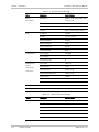
Indicators
(Front Panel)
PWR (green)
On: ASMi-54 is powered on
Off: ASMi-54 is off
TST (yellow)
On: A test is active
Off: A test is inactive
SHDSL SYNC
(green/red)
Green: at least one PME is synchronized and can pass
data
Green blinking: no PME is synchronized and at least one
PME is in training process
Red blinking: no PME is synchronized or in training
process, and at least one PME is in PAF establishment
stage
Red: no PME is synchronized, in training process, or in
PAF establishment stage
ALM (red)
On: A new alarm is detected in the alarm buffer
Off: No alarm currently detected
Indicators
(Rear Panel)
Ethernet Ports
(one or four)
LINK/ACT
(green/yellow)
On (green): Ethernet port link is up
Off: No Ethernet link on the port
Blink (yellow): Ethernet traffic on the port
Power Source
AC/DC Voltage
Wide-range power supply: 100-240 VAC, -48/60 VDC
nominal
Power
Consumption
4 × Ethernet Port
2-wires: 5.2 W
4-wires: 5.5 W
8-wires: 7W
1-14
Technical Specifications
ASMi-54 Ver. 1.0
Installation and Operation Manual
Physical
Chapter 1 Introduction
Plastic Enclosure
Height
43.7 mm (1.7 in)
Width
217 mm (8.5 in)
Depth
170 mm (6.7 in)
Weight
0.5 kg (1.1 lb)
Metal Enclosure
Environment
ASMi-54 Ver. 1.0
Height
43.7 mm (1.7 in)
Width
217 mm (8.5 in)
Depth
170 mm (6.7 in)
Weight
0.7 kg (1.5 lb)
Temperature
0° to 50°C (32° to 122°F)
Humidity
Up to 90%, non-condensing
Technical Specifications
1-15
Chapter 1 Introduction
1-16
Technical Specifications
Installation and Operation Manual
ASMi-54 Ver. 1.0
Chapter 2
Installation and Setup
This chapter includes the following topics:
•
Site requirements and prerequisites
•
Package contents
•
Equipment needed
•
Installation and setup.
2.1
Introduction
An ASMi-54 unit is delivered completely assembled, and is factory set for basic
operation. It is designed for installation as a desktop unit or for mounting in a
19-inch rack. For rack installation instructions, refer to the Rack Mounting Kit for
19-inch Racks guide that comes with the RM kit.
After installing the unit, use an ASCII terminal connected to the CONTROL port to
perform any configuration necessary. The configuration procedures are described
in Chapter 3 and Chapter 4.
If problems are encountered, refer to Chapter 6.
Warning
No internal settings, adjustment, maintenance and repairs should be performed
by either the operator or the user. Such activities must be performed only by
skilled personnel who are aware of the hazards involved.
Always observe standard safety precautions during installation, operation, and
maintenance of this product.
2.2
Site Requirements and Prerequisites
AC-powered ASMi-54 units should be installed within 1.5m (5 feet) of an easily
accessible grounded AC outlet capable of furnishing the required supply voltage,
in the range of 100 to 240 VAC, 50 or 60 Hz.
DC-powered ASMi-54 units require a -48 VDC power source, which must be
adequately isolated from the main supply.
Allow at least 90 cm (36 in) of frontal clearance for operator access. For
continuous product operation allow at least 10 cm of frontal clearance and at
least 15 cm at rear of the unit, for cable connections and ventilation. For proper
ventilation, keep at least 2.5 cm clearance from the sides and top of the product.
ASMi-54 Ver. 1.0
Site Requirements and Prerequisites
2-1
Chapter 2 Installation and Setup
Installation and Operation Manual
The ambient operating temperature is 0º–50ºC (32º–122ºF), at a relative
humidity of up to 90%, non-condensing.
2.3
Package Contents
The package contains the following items:
•
One ASMi-54 unit
•
AC power cord or DC adaptor connector
•
RM-35-2 kit for mounting in a 19” rack (if ordered)
•
Technical documentation CD.
2.4
Equipment Needed
Hand Tools and Kits
ASMi-54 needs no special tools for installation. You need a screwdriver to mount
the unit in a 19-inch rack.
Power Cable
ASMi-54 comes equipped with an appropriate (country or region dependent)
power cord to be connected from the power socket on the rear panel to the
mains.
Cable and Connectors
Refer to the following table to determine what cables and connectors are
required for installation. For all connector pinouts, refer to Appendix A.
Table 2-1. Required Connection Media
2-2
Interface
Cable/Connector
Control port
Straight RS-232/V.24 cable with DB-9 female connector
for ASCII terminal
Fast Ethernet interface
RJ-45, 8-pin connection media
SHDSL Interface
RJ-45, 8-pin connection media
Equipment Needed
ASMi-54 Ver. 1.0
Installation and Operation Manual
2.5
Chapter 2 Installation and Setup
Mounting the Unit
For mounting the ASMi-54 unit in a 19-inch rack, refer to the Rack Mounting Kit
for 19-inch Racks guide that comes with the RM-33-2 kit.
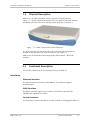
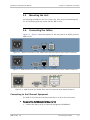
2.6
Connecting the Cables
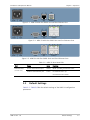
Figure 2-1 - Figure 2-3 show the options for the rear panel of an AC/DC powered
ASMi-54 unit.
Figure 2-1. ASMi-54 with One or Two SHDSL Ports and One Ethernet Port (Plastic Enclosure)
Figure 2-2. ASMi-54 with One or Two SHDSL Ports and Four Ethernet Ports (Plastic Enclosure)
Figure 2-3. ASMi-54 with Four SHDSL Ports and Four Ethernet Ports (Metal Enclosure)
Connecting to the Ethernet Equipment
The ASMi-54 Fast Ethernet interface terminates in an 8-pin RJ-45 connector.
To connect the Fast Ethernet interface (1 or 4):
•
ASMi-54 Ver. 1.0
Connect the LAN to an RJ-45 connector designated 10/100BaseT.
Connecting the Cables
2-3
Chapter 2 Installation and Setup
Installation and Operation Manual
Connecting to the SHDSL Equipment
The SHDSL interfaces terminate in an 8-pin RJ-45 connector.
To connect the SHDSL interface:
•
Connect an SHDSL line to an RJ-45 connector designated SHDSL (1,2,3,4).
Connecting to an ASCII Terminal
To connect the ASCII terminal:
•
Connect the unit's CONTROL port to an ASCII terminal or an out-of-band
management station with a straight RS-232 cable.
2.7
Connecting to Power
ASMi-54 is equipped with a dual input AC/DC power supply. AC or DC power is
supplied to ASMi-54 via a standard 3-prong power input connector on the rear
panel (see Figure 2-1).
Warning
Before connecting this unit to a power source and connecting or disconnecting
any other cable, the protective earth terminals of this unit must be connected to
the protective ground conductor of the mains (AC or DC) power cord. If you are
using an extension cord (power cable) make sure it is grounded as well.
Any interruption of the protective (grounding) conductor (inside or outside the
instrument) or disconnecting of the protective earth terminal can make this unit
dangerous. Intentional interruption is prohibited.
Connecting AC Power
AC power should be supplied through the 1.5m (5 ft) standard power cable
terminated by a standard 3-prong plug. The cable is provided with the unit.
To connect AC power:
1. Connect the power cable to the power connector on the ASMi-54 rear panel.
2. Connect the power cable to the mains outlet.
The unit turns on automatically upon connection to the mains.
Connecting DC Power
DC power is supplied to ASMi-54 via a compatible AC/DC plug for attaching DC
power supply lines.
To connect DC power:
•
2-4
Refer to the DC power supply connection supplement. Refer to the Handling
Energized Products section at the front of this manual for safety instructions.
Connecting to Power
ASMi-54 Ver. 1.0
Chapter 3
Operation
This chapter provides the following information for ASMi-54:
•
Explains power-on and power-off procedures
•
Provides a detailed description of the controls and indicators and their
functions
•
Provides instructions for using a terminal connected to the ASMi-54 control
port
•
Describes how to navigate menus
•
Describes the configuration alternatives.
For a detailed explanation of parameters on the menus, see Chapter 4.
The installation procedures given in Chapter 2 must be completed and checked
before attempting to operate the ASMi-54.
3.1
Turning On the Unit
To turn on the ASMi-54 unit:
•
Connect the power cord to the mains.
The PWR indicator lights up and remains lit as long as ASMi-54 receives
power.
ASMi-54 requires no operator attention once installed, with the exception of
occasional monitoring of front panel indicators. Intervention is only required
when the unit must be configured to its operational requirements, or when
diagnostic tests are performed.
3.2
Indicators
The ASMi-54 LEDs are located on the front panels.
Front Panel Indicators
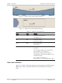
Figure 3-1 and Figure 3-2 show the typical front panel. Table 3-1 describes the
functionality of the ASMi-54 front panel LEDs.
ASMi-54 Ver. 1.0
Indicators
3-1
Chapter 3 Operation
Installation and Operation Manual
Figure 3-1. ASMi-54 Front Panel (Plastic Enclosure)
Figure 3-2. ASMi-54 Front Panel (Metal Enclosure)
Table 3-1. ASMi-54 Front Panel LEDs
Name
Color
Function
PWR
Green
On: ASMi-54 is powered on
Off: ASMi-54 is off
TST
Red
On: A test is active
Off: A test is inactive
ALM
Red
On: Alarm is active
Off: No alarm
SHDSL SYNC
Green/Red
Green: at least one PME is synchronized and can
pass data
Green blinking: no PME is synchronized and at
least one PME is in training process
Red blinking: no PME is synchronized or in
training process, and at least one PME is in PAF
establishment stage
Red: no PME is synchronized, in
training process, or in PAF establishment stage
Rear Panel Indicators
Figure 3-3 - Figure 3-5 show the options for the rear panel of an AC/DC powered
ASMi-54 unit. Table 3-2 lists the functions of the LED indicators on the rear
panel.
3-2
Indicators
ASMi-54 Ver. 1.0
Installation and Operation Manual
Chapter 3 Operation
Figure 3-3. ASMi-54 with One SHDSL Port and One Ethernet Port
Figure 3-4. ASMi-54 with One SHDSL Port and Four Ethernet Ports
Figure 3-5. ASMi-54 with Two SHDSL Ports and Four Ethernet Ports
Table 3-2. ASMi-54 Rear Panel LEDs
Port
Name
Color
Function
Ethernet Ports
(one or four)
ACT for each Ethernet port
Yellow
Blinks according to Ethernet traffic.
LINK for each Ethernet port
Green
On: Ethernet link is up
Off: Ethernet link is down
3.3
Default Settings
Table 3-3 - Table 3-8 lists the default settings of the ASMi-54 configuration
parameters.
ASMi-54 Ver. 1.0
Default Settings
3-3
Chapter 3 Operation
Installation and Operation Manual
Table 3-3. Default System Settings
Menu
Parameter
Default Value
Device
Information
Description
ASMi-54, HW Version 0.00, SW
Version 1.00
Name
ASMi-54
Location
Location of the device
Contact
Name of the contact person
IP Address
0.0.0.0
IP Mask
255.255.255.0
Default Gateway
0.0.0.0
Read Community
Public
Write Community
Private
Trap Community
Public
Host Tagging
Untagged
Host VLAN ID
-
Host Priority Tag
0
User Name
USER ; SU
Old Password
1234
New Password
Empty string
Confirm New Password
Empty string
Telnet Access
Enable
SNMP Access
Enable
Web Access
Enable
Terminal
Baud Rate
115 kbps
Fault Propagation
Network > User Fault Propagation
Disable
Host
Encapsulation
Management
Access
User Access
User Level
Table 3-4. Default Ethernet Settings
Menu
Ethernet
3-4
Default Settings
Parameter
Default Value
Port
1-4
Administrative Status
Up
Auto Negotiation
Enable
Flow Control
Disable
Max Capability Advertised
100BaseTX full-duplex
MDIX Cross Over
Enable
ASMi-54 Ver. 1.0
Installation and Operation Manual
Chapter 3 Operation
Table 3-5. Default SHDSL Settings
Menu
Parameter
Default Value
SHDSL
PCS (Physical Coding Sublayer)
1
Administrative Status
Up
Power Backoff
Disable
Clock Source
RX Clock: STU-R
PME (Physical Medium Entity)
1-4
Administrative Status
Up
Line Probe
Disable
Current Margin
0 dB [Disable]
Worst Margin
0 dB [Disable]
Loop Attenuation Threshold (dB)
[0-127]
0
SNR Margin Threshold(dB) [0-15]
0
PME
Configuration
Table 3-6. Default Bridge Settings
Menu
Parameter
Default Value
Bridge
VLAN Mode
Unaware
Forwarding Mode
Filter
Aging Time
300
Table 3-7. Default Bridge Port Settings
Menu
Parameter
Default Value
Bridge Port
Bridge Port [1-6]
2
Ethernet Port [1-4]
1
Activation
Enable
Port VID / Stacking VID [1-4094]
2
Accept Frame Type
All
Copy Original Priority
Disable
Default Priority Tag [0-7]
0
Egress Tag Handling
None
Ingress Tag Handling
None
Fast Ethernet [Number] /
PCS [Number]
1
Bind
ASMi-54 Ver. 1.0
Default Settings
3-5
Chapter 3 Operation
Installation and Operation Manual
Table 3-8. Default QoS Settings
Menu
Parameter
Default Value
QoS
Priority Classification
802.1p
Priority Mapping
User Priority 0
Traffic Class 0
User Priority 1
Traffic Class 0
User Priority 2
Traffic Class 0
User Priority 3
Traffic Class 0
User Priority 4
Traffic Class 0
User Priority 5
Traffic Class 0
User Priority 6
Traffic Class 0
User Priority 7
Traffic Class 0
3.4
Configuration and Management Alternatives
Configuration and monitoring operations are performed locally from an ASCII
terminal connected to the control port or from a Web browser, via ConfiguRAD or
RADview-Lite, or via SNMP.
Working with the Terminal
ASMi-54 includes a V.24/RS-232 asynchronous DCE port designated CONTROL,
which is terminated in a 9-pin D-type female connector. The control port
continuously monitors the incoming data stream and immediately responds to
any input string received through this port.
The control port can be configured to communicate at the following rates: 9.6,
19.2, or 115.2 kbps.
To start a terminal control session:
1. Make sure all cables and connectors are properly connected.
2. Connect the unit to a PC equipped with an ASCII terminal emulation
application (for example, Windows Hyper Terminal or Procomm).
3. Turn on the control terminal PC and set its default port parameters to 9,600
baud, eight bits/character, one stop bit, no parity.
4. Set the terminal emulator to ANSI emulation (for optimal view of system
menus).
5. Set the terminal emulator to view a 132-character screen width.
6. When the initialization and self-test are over, a menu appears displaying
initialization and self-test results.
3-6
Configuration and Management Alternatives
ASMi-54 Ver. 1.0
Installation and Operation Manual
Chapter 3 Operation
Logging In
To log in:
1. Enter su for user name with read/write permission.
2. Enter 1234 for (default) password.
Note
It is recommended to change default passwords to prevent unauthorized access
to the unit.
Choosing Options
To choose an option:
1. Press the number corresponding to the option, and press <Enter>.
2. Press <S> to save your changes.
ASMi-54 updates its database with a new value or displays a new menu for
the selected option.
3. If you press <ESC> to exit the menu without saving your changes, the
following message appears:
“Do you want to save changes (Y/N/C)?”
Press the appropriate letter to save or not save your changes
(Yes/No/Cancel).
Note
When a menu option has only two values, typing the option number and pressing
<Enter> will toggle between the available values.
Screen Example
The following figure shows a typical screen with main items displayed.
Product title line (ASMi-54)
Short message
1.
2.
3.
4.
5.
Sub Menu>
Sub Menu>
Parameter X [Range] …… (value)
Parameter Y>
(Select value from the list)
Table Z []
prompt>
Main>Configuration>System>
Help line message
Help line of keyboard shortcuts, such as “Esc-prev” for
returning to the previous menu
-----------Division screen line -----------------Scroll messages
Figure 3-6. Sample Screen
ASMi-54 Ver. 1.0
Configuration and Management Alternatives
3-7
Chapter 3 Operation
Installation and Operation Manual
Navigating Tables
Some of the management screens, such as the Manager table, are tables that are
larger than regular menus and may require scrolling to navigate between
parameters. These screens are best viewed when your terminal screen is set to
132 character width.
Use the following keys (case-sensitive) for table navigation:
Table 3-9. Table Navigation Keys
Note
Key
Navigation
<Ctrl>+L
Move left
Left Arrow
Move left
Ctrl>+R
Move right
Right Arrow
Move right
Up Arrow
Move up
Down Arrow
Move down
<Tab>
Select the next changeable cell
G<row number>, <col number>
Go to the specified cell
You can display these navigation keys by typing <?> from a table.
The following figure shows a Static MAC table in VLAN-Aware mode. For
VLAN-unaware bridges, the “VLAN ID” column is not displayed. VLAN ID, MAC
address, and Receive Bridge port are the columns of the parameters to be
defined.
The “A – Add ; R – Remove ; C – Clear” line appears when at least one entry is
configured. If the table is empty, only “A - Add” is displayed.
ASMi-54
Main Menu>Configuration>Applications>Bridge>Static MAC table
VLAN ID
1
| 2
v 3
4
5
1
1
2
3
4
MAC address
Receive Bridge port
11-11-11-11-11-11
22-22-22-22-22-22
33-33-33-33-33-33
44-44-44-44-44-44
55-55-55-55-55-55
1
2
3
3
5
1. MAC address … (11-11-11-11-11-11)
A – Add ; R – Remove ; C – Clear
ESC-Previous menu; !-Main menu; &-Exit; ?-Help
Figure 3-7. Sample Table Screen (Static MAC Table)
3-8
Configuration and Management Alternatives
ASMi-54 Ver. 1.0
Installation and Operation Manual
Chapter 3 Operation
Help Screen Example
The following figure shows a typical Help screen, which summarizes the keyboard
shortcuts that are available in the functional screen from which the Help screen
was invoked.
The Help screen is invoked by pressing SHIFT-/ (the ‘?’ symbol) from the relevant
functional screen. However, not all functional screens have Help available.
Table Hot Keys
'L'
'd'
'a'
'm'
'c'
TAB
-
move left
scroll down
'D' - move down
add row
't' - remove row
represent entry as menu
clear table
select next changeable cell
S <row number>,<col number> - select cell
Figure 3-8. Typical Help Screen
Working with ConfiguRAD
ConfiguRAD is a Web-based remote access terminal management software. It
provides a user-friendly interface for configuring, collecting statistics and
performing diagnostic tests on the unit.
Web Browser Requirements
The following Web browsers can be used to access the ASMi-54 ConfiguRAD
supervision utility from any location using Internet protocols.
•
Internet Explorer version 6.0 and up, running on Windows™ 98, Windows™
2000, Windows™ XP
•
Netscape Communicator version 7.1 and up, running on Windows™ NT or
Unix
•
Firefox version 1.0.4 and up
•
Mozilla version 1.4.3 and up.
Logging In
To log in via Web browser:
1. Connect the Ethernet port to the LAN.
2. Open the Web browser.
3. Disable any pop-up blocking software, such as Google Popup Blocker.
4. Enter the IP address of the ASMi-54 in the address field of the browser in the
following format: http://’IP address’ (‘IP address’ stands for the actual ASMi54 IP address which has to be assigned via an ASCII terminal).
5. Press <Enter> to command the browser to connect.
ASMi-54 Ver. 1.0
Configuration and Management Alternatives
3-9
Chapter 3 Operation
Installation and Operation Manual
6. After the opening window is displayed, click LOGIN.
7. In the Password Entry window, enter your user name (read/write user default
is su) and password (default is 1234).
The ConfiguRAD Main menu is displayed.
Note
• It is recommended to change default passwords to prevent unauthorized
access to the unit.
• ASMi-54 allows six management sessions to be active simultaneously:
one network session (Telnet, ConfiguRAD, RADview-Lite) and one ASCII
terminal session.
• If no user input is detected for 5 minutes during a ConfiguRAD session,
ASMi-54 automatically disconnects from the management station.
Navigating the ConfiguRAD Menus
At the left-hand bottom corner, ConfiguRAD provides auxiliary management tools:
•
Status – shows the number of users currently managing the unit.
•
Trace – opens an additional pane for system messages, progress indicators
(ping, software and configuration file downloads) and alarms.
•
Refresh All – refreshes the data currently displayed.
To choose an option:
1. Click a link in the ConfiguRAD screen to display the next menu.
2. Once the target screen is displayed, select a value from the drop-down box or
enter it in a text box.
Menu Map
Use the menu maps on the following pages as a reference aid when performing
configuration and control functions (see Figure 3-9 Figure 3-11).
Figure 3-9. Main Menu Map
3-10
Configuration and Management Alternatives
ASMi-54 Ver. 1.0
Installation and Operation Manual
Chapter 3 Operation
Figure 3-10. Configuration Menu Map – Page 2
ASMi-54 Ver. 1.0
Configuration and Management Alternatives
3-11
Chapter 3 Operation
Installation and Operation Manual
Figure 3-11. Monitoring Menu Map – Page 3
3-12
Configuration and Management Alternatives
ASMi-54 Ver. 1.0
Installation and Operation Manual
3.5
Chapter 3 Operation
Turning Off the Unit
To power off the ASMi-54 unit:
•
ASMi-54 Ver. 1.0
Remove the power cord from the power source.
Turning Off the Unit
3-13
Chapter 3 Operation
3-14
Turning Off the Unit
Installation and Operation Manual
ASMi-54 Ver. 1.0
Chapter 4
Configuration
This chapter describes how to configure the ASMi-54 for management and
operational tasks. Configuration screens are shown, and configuration
parameters explained.
Note
The configuration screens illustrated in this chapter are taken from a terminal
screen, but most of the menus are similar to those viewed in Telnet and
ConfiguRAD.
This chapter includes the following sections:
•
Configuring for Management
•
Configuring for Operation
•
Additional Tasks.
For a complete list of all menu items, see menu in Chapter 3.
For instructions on accessing and navigating the screens, see Chapter 3.
4.1
Configuring for Management
This section describes how to configure the ASMi-54 for management functions.
Entering Device Information
The ASMi-54 management software allows you to assign a name for the unit, and
specify its location to distinguish it from the other devices installed in your
system. A contact person can also be assigned. Each of these fields can hold up
to 50 characters.
To enter device information:
1. Select Main Menu>Configuration.
The Configuration screen appears (see Figure 4-1).
2. Select System.
The Configuration System screen appears (see Figure 4-2).
3. Select Management.
The Management screen appears (see Figure 4-3).
4. Select Device Info.
The Device Information screen appears (see Figure 4-4 for a typical
screen example). The description of the unit is factory set.
ASMi-54 Ver. 1.0
Configuring for Management
4-1
Chapter 4 Configuration
Installation and Operation Manual
5. Select Device Name, and type a name for the unit.
The default name is ASMi-54.
6. Select Location, and type a location name/description.
7. Select Contact Person, and type the name of a contact person for this unit.
8. Press <S> to save the parameters.
The parameters are saved in the system.
ASMi-54
Main Menu > Configuration>
1. System
2. Physical Layer
3. Applications
>
>
>
C-Clear All Statistics
ESC-Previous menu; !-Main menu; &-Exit; ?-Help
Figure 4-1. Configuration Screen
ASMi-54
Main Menu > Configuration > System
1.
2.
3.
4.
5.
Management
Terminal
Fault Propagation
Date and Time
Factory Defaults
>
>
>
ESC-Previous menu; !-Main menu; &-Exit
Figure 4-2. Configuration System Screen
ASMi-54
Main Menu > Configuration >System > Management
1.
2.
3.
4.
Device information
Host
Managers list
Management Access
>
>
[] >
>
ESC-Previous menu; !-Main menu; &-Exit
Figure 4-3. Management Screen
4-2
Configuring for Management
ASMi-54 Ver. 1.0
Installation and Operation Manual
Chapter 4 Configuration
ASMi-54
Main Menu > Configuration > System > Management > Device Information
Description
… (ASMi-54, HW Version 0.00, SW Version 1.00)
1. Name
2. Location
3. Contact
… (ASMi-54)
… (Location of the device)
… (Name of the contact person)
S - Save
ESC-Previous menu; !-Main menu; &-Exit
Figure 4-4. Typical Device Information Screen
Configuring IP Host Parameters
You can manage the unit via a network management station connected to one of
the unit’s ports. To establish a proper connection, it is necessary to configure the
Host IP parameters. In addition, by selecting a forwarding mode and VLAN
parameters, it is possible to create a separate management VLAN.
To define the Host IP parameters:
1. Select Main Menu>Configuration>System>Management.
The Management screen appears (see Figure 4-3).
2. Select Host IP.
The Host IP screen appears (see Figure 4-5).
3. In the Host IP screen:
1. Select IP Address and enter the IP address of the IP host.
2. Select IP Mask and enter the host IP subnet mask.
3. Select Default Gateway and enter the default gateway IP address.
4. Select Read Community and type the name of a community with
read-only authorization.
The default is Public.
5. Select Write Community and type the name of a community with write
authorization.
6. Select Trap Community and type the name of a community to which the
unit should send traps.
7. Select Encapsulation to define VLAN tagging performed by the host.
The Encapsulation screen appears (see Figure 4-6).
4. From the Encapsulation screen, select Host Tagging and toggle between
Untagged and Tagged.
Untagged – The host sends and receives frames with no VLAN tag
to/from the bridge.
ASMi-54 Ver. 1.0
Configuring for Management
4-3
Chapter 4 Configuration
Installation and Operation Manual
Tagged – The host receives frames only when they are tagged with the
host’s VLAN ID, and it sends frames to the bridge with this tag.
Note
When Host Tagging is set to Tagged, two parameters are added to the menu:
Host VLAN ID and VLAN Priority.
The default is Untagged.
5. Select Host VLAN ID to specify the host VLAN ID (1–4094).
Enter the number of the VLAN ID.
6. Select VLAN Priority to specify the priority level for the host VLAN (0–7).
7. Press <S> to save the changes.
8. Return to the Host IP screen and press <S> to save the parameters.
The changes are saved in the unit.
ASMi-54
Main Menu > Configuration > System > Management > Host IP
1.
2.
3.
4.
5.
6.
7.
IP Address
Mask
Default gateway
Read community
Write community
Trap community
Encapsulation
…
…
…
…
…
…
>
(172.17.143.140)
(255.255.255.0)
(172.17.143.1)
(public)
()
()
S - Save
ESC-Previous menu; !-Main menu; &-Exit
Figure 4-5. Host IP Screen
ASMi-54
Main Menu > Configuration > System > Management > Host IP >
Encapsulation
1
1. Host tagging
2. Host VLAN ID [1-4094]
3. Host Priority Tag [0-7]
> (Tagged)
… (2)
… (0)
S - Save
ESC-Previous menu; !-Main menu; &-Exit
Figure 4-6. Encapsulation Screen
4-4
Configuring for Management
ASMi-54 Ver. 1.0
Installation and Operation Manual
Chapter 4 Configuration
Configuring Terminal Parameters
The Terminal is connected to the Control Port. The management software allows
you to configure the terminal baud rate.
Note
The Baud Rate parameter is masked during a Telnet session.
To change the terminal baud rate:
1. Select Main Menu>Configuration>System.
The Configuration System screen appears (see Figure 4-2).
2. Select Terminal.
The Terminal screen appears (see Figure 4-7).
3. Select Baud Rate.
The Baud Rate screen appears (see Figure 4-8).
4. Select the desired baud rate (9600, 19200, 115200).
The default baud rate is 9600.
5. Return to the Terminal screen and press <S> to save the changes.
The changes are saved in the unit.
ASMi-54
Main Menu > Configuration > System > Terminal
1. Baud rate
> (9600 bps)
S - Save
ESC-Previous menu; !-Main menu; &-Exit
Figure 4-7. Terminal Screen
ASMi-54
Main Menu>Configuration>System>Terminal>Baud rate (19200 bps)
1. 9600 bps
2. 19200 bps
3. 115200 bps
ESC-Previous menu; !-Main menu; &-Exit
Figure 4-8. Baud Rate Screen
ASMi-54 Ver. 1.0
Configuring for Management
4-5
Chapter 4 Configuration
Installation and Operation Manual
Setting Management Access
To modify Telnet, SNMP, or WEB access permissions for a user:
1. Select Main Menu>Configuration>System>Management.
The Management screen appears (see Figure 4-3).
2. Select Management Access.
The Management Access screen appears (see Figure 4-9).
3. Select the access level you wish to change: Telnet Access, SNMP Access, or
WEB Access.
4. Select the permission setting for this access level: Enable, Disable or Manage
Only.
The default is Enable.
5. Press <S> to save the changes.
The changes are saved in the unit.
ASMi-54
Main Menu > Configuration > System > Management > Management
Access
1.
2.
3.
4.
User Access
Telnet Access
SNMP Access
WEB Access
(Enable)
(Enable)
(Enable)
ESC-Previous menu; !-Main menu; &-Exit
Figure 4-9. Management Access Screen
Configuring the Network Managers
The network management stations to which the SNMP agent sends traps can be
defined or modified. Up to ten managers can be defined. Entering the IP address
and corresponding subnet mask defines each management station. In addition,
you can temporarily prevent a manager station from receiving traps by masking
the network manager.
To edit the manager list:
1. Select Main Menu>Configuration>System>Management.
The Management screen appears (see Figure 4-3).
2. Select Managers List.
The Management List screen appears (see Figure 4-10).
3. To add a new network manager, press <A> (Add).
4. Move the cursor to the Manager IP cell you wish to modify by pressing the
Tab key. The selected cell is highlighted and the value appears in the Change
cell field.
4-6
Configuring for Management
ASMi-54 Ver. 1.0
Installation and Operation Manual
Chapter 4 Configuration
5. Select Change Cell, and press <Enter> to enter a new IP address for the
selected network manager.
6. Move the cursor to the Trap field and toggle between Mask and Unmask to
mask or unmask traps for the selected management station.
The default is Unmask.
7. Press <S> to save the changes.
ASMi-54
Main Menu > Configuration > System > Management > Managers List
IP address
1.1.1.1
2.2.2.2
3.3.3.3
4.4.4.4
5.5.5.5
1.
| 2.
v 3.
4.
5.
1. Change cell
Trap
Unmask
Unmask
Mask
Unmask
Unmask
… (1.1.1.1)
ESC-Previous menu; !-Main menu; &-Exit; ?-Help
Figure 4-10. Manager List Screen
ASMi-54
Main Menu > Configuration > System > Management > Managers List
Manager IP Mask
Manager Trap Mask
Save All
>
... (255.255.255.0)
... (Enable)
ESC-prev menu; !-main menu; &-exit;
1 user(s)
Figure 4-11. Manager List Screen, Add Mode
ASMi-54 Ver. 1.0
Configuring for Management
4-7
Chapter 4 Configuration
4.2
Installation and Operation Manual
Configuring for Operation
This section explains how to operate the unit.
Setting Device-Level Parameters
This section includes procedures for setting the configuring fault propagation
options.
Configuring Fault Propagation
When the Network > User Fault Propagation feature is enabled, the LAN ports are
deactivated when the PCS uplink goes down. They will come up again once the
PCS port is resynchronized.
To configure the fault propagation:
1. Select Main Menu>Configuration>System.
The Configuration System screen appears (see Figure 4-2).
2. Select Fault Propagation.
The Fault Propagation screen appears (see Figure 4-12).
3. Select Network>User Fault Propagation and toggle between Enable and
Disable.
4. Press <S> to save the changes.
ASMi-54
Main Menu > Configuration > System > Fault Propagation
1. Network - >
User Fault Propagation
(Disable)
S - Save
ESC-Previous menu; !-Main menu; &-Exit
Figure 4-12. Fault Propagation Screen
Configuring Date and Time
The Date and Time screen is used to configure the NTP client parameters.
The NTP client is used as a means to receive the date and time from the network.
When the NTP server is properly configured and accessible, the device displays
the real date and time as was received from the NTP server, instead of the
system uptime, which is the default state.
4-8
Configuring for Operation
ASMi-54 Ver. 1.0
Installation and Operation Manual
Chapter 4 Configuration
To configure the NTP client parameters:
1. Select Main Menu>Configuration>System.
The Configuration System screen appears (see Figure 4-2).
2. Select Date and Time.
The Date and Time screen appears (see Figure 4-13). The parameters are
described in Table 4-1.
3. Press <S> to save the changes.
ASMi-54
Main Menu > Configuration > System > Date and Time
1
2
3
4
5
Date
Time
NTP Mode
GMT
NTP Server IP Address
NTP Update Interval (sec)
Send Initiated NTP Request
...(01-10-1949)
...(00:00:01)
> (Unicast Client)
> (0)
...(172.17.163.93)
...(5)
ESC-Previous menu; !-Main menu; &-Exit
Figure 4-13. Date and Time Screen
Table 4-1. Date and Time Configuration Parameters
Parameter
Possible Values
Remarks
NTP Mode
Unicast Client
NTP request is sent to a specific IP address
Disable
Default: Disable
-12 ... 12
Offset from Greenwich Mean Time
GMT
Default: 0
NTP Server IP
Address
xxx.xxx.xxx.xxx
Default: 0.0.0.0
NTP Update
Interval (sec)
0 (disable)
Time (in seconds) between NTP requests
1 ... 4294967295
Default: 0 (disable)
Send Initiated
NTP Request
Each time this is pressed, an NTP request is sent regardless of the
NTP update interval.
Configuring Physical-Level Port Parameters
ASMi-54 has one or four Fast Ethernet interfaces and up to four SHDSL interface.
The Fast Ethernet and SHDSL configuration menus are accessed from the Physical
Layer menu.
ASMi-54 Ver. 1.0
Configuring for Operation
4-9
Chapter 4 Configuration
Installation and Operation Manual
Configuring the Fast Ethernet Port
The following parameters can be configured for the Ethernet ports at the physical
level:
•
Administrative Status
•
Autonegotiation
•
Flow Control
•
Maximum advertised capability for autonegotiation procedure
•
Data rate and duplex mode (only when autonegotiation is disabled)
•
MDIX Auto Cross Over.
To configure the Fast Ethernet port:
1. Select Main Menu>Configuration.
The Configuration screen appears (see Figure 4-1).
2. Select Physical Layer.
The Physical Layer screen appears (see Figure 4-14).
3. Select Fast Ethernet.
The Fast Ethernet Port Configuration screen appears (see Figure 4-15).
The parameters are described in Table 4-2.
4. Press <S> to save the changes.
ASMi-54
Main Menu > Configuration > Physical Layer
1. Ethernet
2. SHDSL
>
>
>
ESC-Previous menu; !-Main menu; &-Exit
Figure 4-14. Physical Layer Screen
4-10
Configuring for Operation
ASMi-54 Ver. 1.0
Installation and Operation Manual
Chapter 4 Configuration
ASMi-54
Main Menu > Configuration > Physical Layer > Ethernet
1.
2.
3.
4.
5.
Port
Administrative Status
Auto Negotiation
Flow Control
Max Capability Advertised
MDIX Auto Cross Over
(1)
(Up)
(Enable)
(Disable)
(100base – TX Full Duplex)
(Enable)
F-Forwards; B-Backwards; S-Save
ESC-Previous menu; !-Main menu; &-Exit
Figure 4-15. Fast Ethernet Port Configuration Screen
Table 4-2. Fast Ethernet Port Configuration Parameters
Parameter
Possible Values
Remarks
Port
1 or 4
The Fast Ethernet port number.
Default: 1
Administrative
Status
Up
The Fast Ethernet activation.
Down
Default: Up
Auto Negotiation
Enable
Enables autonegotiation signaling over the Ethernet.
Disable
Default: Enable
Enable
Used to configure the default administrative PAUSE mode for
this interface.
Flow Control
Disable
Default: Disable
Max Capability
Advertised
Speed & Duplex
10baseT Half Duplex
10baseT Full Duplex
Specifies the set of capabilities advertised by the local
autonegotiation entity.
100baseTX Half Duplex
Default: 100BaseTX full-duplex
100base TX Full Duplex
Note: Appears only when autonegotiation is enabled.
10baseT Half Duplex
The static speed and duplex that the port will use.
10baseT Full Duplex
Default: 100BaseTX full-duplex
100baseTX Half Duplex
Note: Appears only when autonegotiation is disabled.
100base TX Full Duplex
MDIX Auto Cross
Over
ASMi-54 Ver. 1.0
Enable
Enables and disables Auto Cross Over functionality.
Disable
Default: Enable
Configuring for Operation
4-11
Chapter 4 Configuration
Installation and Operation Manual
Configuring the SHDSL Ports
This section includes procedures for configuring the SHDSL PCS ports, configuring
the SHDSL PME ports, and setting the clock source.
Configuring the SHDSL PCS Ports
To configure SHDSL PCS ports:
1. Select Main Menu > Configuration > Physical Layer.
The Physical Layer screen appears (see Figure 4-14).
2. Select SHDSL.
The SHDSL PCS Port Configuration screen appears (see Figure 4-16). The
parameters are described in Table 4-3.
ASMi-54
Main Menu > Configuration > Physical Layer > SHDSL
PCS (Physical Coding Sublayer)
Administrative Status
Power Backoff
(1)
(Up)
(Disable)
1. Clock Source
2. PME Configuration
(RX Clock: STU-R)
>
>
F-Forward
ESC-Previous menu; !-Main menu; &-Exit
Figure 4-16. SHDSL PCS Port Configuration Screen
Table 4-3. SHDSL PCS Port Configuration Parameters
Parameter
Possible Values
Remarks
PCS (Physical
Coding
Sublayer)
1
Index of the SHDSL PCS.
Administrative
Status
Up
Administrative status of the SHDSL PCS.
Down
Default: Up
Power Backoff
Disable
The power backoff mode.
Default: 1
Default: Disable
Note: This parameter is Read Only and cannot be configured.
Clock Source
Internal: STU-C
RX Clock: STU-R
The source clock determines SHDSL mode (STU-C or STU-R). If source
clock is receive (RX), source port is the first connected SHDSL line.
Default: RX Clock: STU-R
4-12
Configuring for Operation
ASMi-54 Ver. 1.0
Installation and Operation Manual
Chapter 4 Configuration
Parameter
Possible Values
Remarks
Transmission
Mode
Annex A/F
The regional setting of the SHDSL span.
Annex B/G
Default: Annex B/G
Note: This parameter can be configured in STU-C mode only.
PME
Configuration
The configuration of the PME (Physical Medium Entity),
see Configuring the SHDSL PME Ports.
Configuring the Clock Source
Transmitted data can be clocked either from an internal clock within the ASMi-54,
or from an external clock via the SHDSL links.
To configure the clock source:
1. Select Main Menu>Configuration>Physical Layer>SHDSL.
The SHDSL PCS Port Configuration screen appears (see Figure 4-16).
2. Select Clock Source and toggle between Internal and RX Clock.
Internal: STU-C – To set the internal clock as the clock source.
RX Clock: STU-R – To set an external clock (from SHDSL link) to clock the
clock source.
3. Press <S> to save the changes.
Configuring the SHDSL PME Ports
To configure the SHDSL PME ports:
1. Select Main Menu>Configuration>Physical Layer>SHDSL.
The SHDSL PCS Port Configuration screen appears (see Figure 4-16).
2. Select PME Configuration.
The SHDSL PME Port Configuration screen appears (see Figure 4-17). The
parameters are described in Table 4-4.
3. Press <F> to change the number of the PME (Physical Medium Entity).
4. Press <S> to save the changes.
ASMi-54 Ver. 1.0
Configuring for Operation
4-13
Chapter 4 Configuration
Installation and Operation Manual
ASMi-54
Main Menu > Configuration > Physical Layer > SHDSL > PME
Configuration
PME (Physical Medium Entity)
(1)
1.
2.
3.
4.
5.
6.
7.
(Up)
(Disable)
(192000)
(0)
(0)
(0)
(0)
Administrative Status
Line Probe
Line Rate
Current Margin
>
Worst Margin
>
Loop Attenuation Threshold (dB)[0…127]
SNR Margin Threshold (dB)[0…15]
>
F-Forward
ESC-Previous menu; !-Main menu; &-Exit
Figure 4-17. SHDSL PME Port Configuration Screen
Table 4-4. SHDSL PME Port Configuration Parameters
Parameter
Possible Values
Remarks
PME (Physical
Medium Entity)
1–4
Index of the SHDSL PME.
Administrative
Status
Up
Administrative status of the SHDSL PME.
Down
Default: Up
Line Probe
Disable
Enable/disable support for Line Probe of the units in an SHDSL span.
Enable
Default: Disable
1920005696000 bps
The transmission rate for the associated SHDSL PME in bits-persecond (bps) and includes both payload (user data) and any
applicable framing overhead.
Line Rate
Default: 1
Default: 192000
Current Margin
-10…0…21
The downstream/upstream current condition target SNR margin in
dB. To configure the current margin, see Configuring the SHDSL PME
Current Margin.
Default: 0 (Disable)
Note: Appears only when Line Probe is “Enable”.
Worst Margin
-10…0…21
The downstream/upstream worst case target SNR margin in dB. To
configure the worst margin, see Configuring the SHDSL PME Worst
Margin.
Default: 0 (Disable)
Note: Appears only when Line Probe is “Enable”.
Loop
Attenuation
Threshold (dB)
4-14
0…127
Configuring for Operation
The loop attenuation alarm threshold.
Default: 0
ASMi-54 Ver. 1.0
Installation and Operation Manual
Chapter 4 Configuration
Parameter
Possible Values
Remarks
SNR Margin
Threshold (dB)
0…15
The SNR margin alarm threshold.
Default: 0
Configuring the SHDSL PME Current Margin
Note
Only available in STU-R mode.
To configure the SHDSL PME current margin:
1. Select Main Menu>Configuration>Physical Layer>SHDSL>PME Configuration.
The SHDSL PME Port Configuration screen appears (see Figure 4-17).
2. Select Current Margin.
The SHDSL PME Current Margin screen appears (see Figure 4-18).
3. Select an item (1-32).
4. Press <S> to save the changes.
Configuring the SHDSL PME Worst Margin
Note
Only available in STU-R mode.
To configure the SHDSL PME worst margin:
1. Select Main Menu>Configuration>Physical Layer>SHDSL>PME Configuration.
The SHDSL PME Port Configuration screen appears (see Figure 4-17).
2. Select Worst Margin.
The SHDSL PME Worst Margin screen appears (see Figure 4-18).
3. Select an item (1-32).
4. Press <S> to save the changes.
ASMi-54 Ver. 1.0
Configuring for Operation
4-15
Chapter 4 Configuration
Installation and Operation Manual
ASMi-54
Main Menu > Configuration > Physical Layer > SHDSL > PME
Configuration > Current Margin
1. –10 dB
2. –9 dB
3. –8 dB
4. –7 dB
5. –6 dB
6. –5 dB
7. –4 dB
8. –3 dB
9. –2 dB
10. –1 dB
11. 0 dB (Disable)
12. 1 dB
13. 2 dB
14. 3 dB
15. 4 dB
16. 5 dB
17.
18.
19.
20.
21.
22.
23.
24.
25.
26.
27.
28.
29.
30.
31.
32.
6 dB
7 dB
8 dB
9 dB
10 dB
11 dB
12 dB
13 dB
14 dB
15 dB
16 dB
17 dB
18 dB
19 dB
20 dB
21 dB
>
ESC-Previous menu; !-Main menu; &-Exit
Figure 4-18. SHDSL PME Current Margin Screen
Note
The SHDSL PME Worst Margin screen is the same as the SHDSL PME Current
Margin screen except for the heading.
Configuring the Internal Bridge
The internal bridge connects the unit’s ports. Configure the bridge for it to
properly process the VLAN tags to maintain priority of the data flows.
The bridge operates in transparent mode (learning is disabled) or filtered mode
(learning and filtering are enabled).
To configure the internal bridge:
1. Select Main Menu>Configuration.
The Configuration screen appears (see Figure 4-1).
2. Select Applications.
The Applications screen appears (see Figure 4-19).
3. Select Bridge.
The Bridge screen appears (see Figure 4-20). The parameters are
described in Table 4-5.
4. For Static MAC Table configuration, see Using the Static MAC Table.
5. For Bridge Port configuration, see Configuring the Bridge Ports.
4-16
Configuring for Operation
ASMi-54 Ver. 1.0
Installation and Operation Manual
Chapter 4 Configuration
6. For VLAN Membership configuration (in Aware bridge only), see Configuring
VLAN Membership.
7. Press <S> to save the changes.
ASMi-54
Main Menu > Configuration > Applications
1. Bridge
2. QoS
>
>
ESC-Previous menu; !-Main menu; &-Exit
Figure 4-19. Applications Screen
ASMi-54
Main Menu > Configuration > Applications > Bridge
1.
2.
3.
4.
5.
6.
VLAN Mode
Forwarding Mode
Aging time (sec) [300 – 4080]
Static MAC table
Bridge port
VLAN membership
(Aware)
(Filter)
… (300)
[]>
>
>
S - Save
ESC-Previous menu; !-Main menu; &-Exit
Figure 4-20. Bridge Screen
Table 4-5. Bridge Parameters
Parameter
Possible Values
Remarks
VLAN Mode
Aware
Forwarding is based on MAC address only or on VLAN+MAC.
Unaware
• Aware – Bridge operates according to 802.1Q
• Unaware – Operates according to 802.1D.
Default: Unaware
Forwarding
Mode
Filter
Determines whether the bridge learns MAC addresses.
Transparent
• Filter – Learning and filtering are enabled
• Transparent – No learning is performed. Each packet received is
forwarded to all other ports automatically, unless static MAC is
used.
Default: Filter
Aging Time
(sec)
300…4080
Aging time for entries in the MAC table. If the aging time elapses,
and no frame has been received from the MAC, it is erased from the
MAC table.
Default: 300 seconds
ASMi-54 Ver. 1.0
Configuring for Operation
4-17
Chapter 4 Configuration
Installation and Operation Manual
Using the Static MAC Table
Static MAC addresses are stored in the MAC table.
To add a static MAC address:
1. Select Main Menu>Configuration>Applications> Bridge.
The Bridge screen appears (see Figure 4-20).
2. Select Static MAC Table.
The Static MAC Table screen appears (see Figure 4-21), with VLAN ID
entries for a VLAN-aware bridge only.
3. To add a static MAC address, press A (Add Entry).
The Static MAC Table screen display changes, as shown in Figure 4-22.
4. In Add mode, perform the following:
1. Select MAC Address, and enter a new MAC address.
2. Select VLAN ID, and choose a VLAN ID for the MAC address, 1-4094.
3. Select Receive Bridge Port, and choose the interface this MAC address
should be attached to.
4. Press <S> to save the MAC address.
5. Press <ESC> to return to the Static MAC Table screen.
5. Return to the Static MAC Table screen and press <S> to save the table.
ASMi-54
Configuration > Applications > Bridge > Static MAC Table
VLAN ID
1
| 2
v 3
4
5
1
1
2
3
4
MAC address
Receive Bridge port
11-11-11-11-11-11
22-22-22-22-22-22
33-33-33-33-33-33
44-44-44-44-44-44
55-55-55-55-55-55
1
2
3
3
5
1. MAC address … (11-11-11-11-11-11)
C – Clears the table ; S – Save ; A – Add entry
ESC-Previous menu; !-Main menu; &-Exit; ?-Help
Figure 4-21. Static MAC Table Screen
4-18
Configuring for Operation
ASMi-54 Ver. 1.0
Installation and Operation Manual
Chapter 4 Configuration
ASMi-54
MAC table handling
1. MAC address
2. VLAN ID [1-4094]
3. Bridge port [1 – N]
… (00-00-00-00-00-00)
(1)
(1)
S - Save
ESC-Previous menu; !-Main menu; &-Exit; ?-Help
Figure 4-22. Static MAC Table, Add Mode
To remove a static address from the table:
1. Select Main Menu>Configuration>Applications> Bridge>Static MAC Table.
The Static MAC Table screen appears (see Figure 4-21).
2. Select a MAC address that you want to remove and press <R>.
The MAC address is deleted from the table.
To clear the MAC table:
1. Select Main Menu>Configuration>Applications>Bridge>Static MAC Table.
The Static MAC Table screen appears (see Figure 4-21).
2. Press <C> to clear the table.
The following message appears:
Are you sure (Y/N)?
3. Press <Y> to confirm deletion of all MAC addresses from the table.
Configuring the Bridge Ports
The unit is supplied with the Bridge Ports preconfigured for basic use. The
factory-set configuration is shown in Table 4-6.
Note
To reconfigure the ports, first delete the configuration for each port.
Table 4-6. Factory Set Bridge Port Settings
ASMi-54 Ver. 1.0
Bridge Port
Configured to
1
Reserved for management host
2
Fast Ethernet Port 1
3
Fast Ethernet Port 2
4
Fast Ethernet Port 3
5
Fast Ethernet Port 4
6
PCS Port 1
Configuring for Operation
4-19
Chapter 4 Configuration
Installation and Operation Manual
To delete a factory-set bridge port configuration:
1. Select Main Menu>Configuration>Applications>Bridge.
The Bridge screen appears (see Figure 4-20).
2. Select Bridge Port.
The Bridge Ports screen appears (see Figure 4-23).
3. Type the Bridge Port number.
Note
Bridge Port 1 is reserved for management.
4. Press <F> to toggle through the Bridge ports.
5. Press <D> to delete the configuration.
6. Press <S> to save the changes.
ASMi-54
Main Menu > Configuration > Applications > Bridge > Bridge Port
1. Bridge port [1 – 6]
2. Bind
3. Activation
4. Ingress filtering
5. Accept frame type
6. Port VID / Stacking VID [1 – 4094]
7. Copy Origin Priority
8. Default Priority Tag [0-7]
9. Egress Tag Handling
10. Ingress Tag Handling
...(2)
(Eth-1)
(Enable)
(Disable)
(All)
...(3)
(Disable)
...(4)
(None)
(None)
F-Forwards; B-Backwards; S - Save
ESC-Previous menu; !-Main menu; &-Exit; ?-Help
Figure 4-23. Bridge Ports Screen
4-20
Configuring for Operation
ASMi-54 Ver. 1.0
Installation and Operation Manual
Chapter 4 Configuration
Table 4-7. Bridge Port Parameters
Parameter
Possible Values
Remarks
Bridge Port
Number
1-6
Bridge port number.
Default: 2
Note: Bridge port number 1 is reserved for the host bridge port.
The type of port to be bound. To configure a bridge port, see
Bind
Activation
Configuring a Bridge Port.
Enable
Disable
Specifies if this port is part of the bridge or not. Press the option
number to toggle enable/disable.
Default: Enable
Ingress Filtering
Enable
Disable
When Enabled, the device discards incoming frames for VLANs which
do not include this Port in its Member set. When Disabled, the port
accepts all incoming frames.
Default: Disable
Note: Appears only when in VLAN-Aware mode.
Accept Frame
Type
All
Tag Only
Tag Only specifies that the device discards untagged frames. All
specifies that untagged frames received on this port are accepted
and assigned to the PVID for this port.
Default: All
Note: Appears only when in VLAN-Aware mode.
Port VID /
Stacking VID
1–4094
This is the PVID, the VLAN ID assigned to untagged frames or
priority-tagged frames received on this port. If Stacking is enabled,
this is the tag to be added.
Default: 2
Copy Original
Priority
Enable
Copy priority from original frame.
Disable
Default: Disable
Default Priority
Tag
0-7
Default VLAN frame priority. Applies to untagged frames.
Egress Tag
Handling
Stacking
Stacking: Adds the PVID to every frame transmitted from the port.
Stripping
Stripping: Removes the first VLAN tag from every transmitted frame,
on the egress of the port.
Default: 0
None
Default: None
Ingress Tag
Handling
Stacking
Stripping
None
Stacking: Adds the PVID to every frame received on the ingress of
the port.
Stripping: Removes the first VLAN tag from every received frame, on
the ingress of the port.
Default: None
ASMi-54 Ver. 1.0
Configuring for Operation
4-21
Chapter 4 Configuration
Installation and Operation Manual
Configuring a Bridge Port
To configure a bridge port:
1. Select Main Menu>Configuration>Applications>Bridge>Bridge Ports.
The Bridge Ports screen appears (see Figure 4-23).
2. Select Bind to define which port the bridge port should be bound to.
The Bind screen appears (see Figure 4-24).
Note
• The Bind option does not appear for Bridge port 1 (Management host). The
host cannot be bound.
• Usually there is not need to bind BPs, as all are bound in the default
configuration.
ASMi-54
Configuration > Application > Bridge > Bridge ports > Bind
1. Fast Ethernet [number] / PCS [Number]
...(1)
ESC-Previous menu; !-Main menu; &-Exit; ?-Help
Figure 4-24. Bridge Ports Bind Screen
3. Select Fast Ethernet, and type the number of the Fast Ethernet port / PCS to
which you want to bind the bridge port.
Note
The Bridge may have a total of six Bridge Ports (BP). BP1 is dedicated to the IP
Host. BP2-6 may be bound to Fast-Ethernet ports 1–4 or to the PCS port.
4. Press <S> to save the changes.
5. Press <ESC> to return to the Bridge Ports menu.
6. In the Bridge Ports menu, configure the Bridge Ports parameters
(see Table 4-7). The settings pertain to the port to which you bound the
bridge port in the previous steps.
7. Press <S> to finish the bridge ports configuration.
Configuring VLAN Membership
To configure VLAN Membership:
1. Select Main Menu>Configuration>Applications>Bridge.
The Bridge screen appears (see Figure 4-20).
2. Select VLAN Membership.
The VLAN Membership screen appears (see Figure 4-25).
3. Select VLAN ID, and type the VLAN ID you wish to configure.
4. Select Egress Tagged Ports. Define the set of ports to transmit packets for
this VLAN as tagged.
4-22
Configuring for Operation
ASMi-54 Ver. 1.0
Installation and Operation Manual
Chapter 4 Configuration
5. Select Egress Untagged Ports. Define the set of ports to transmit packets for
this VLAN as untagged.
6. Press <A> to add BP to this VLAN.
7. Press <F> to toggle through the VLAN IDs.
8. Press <R> to delete the configuration.
9. Press <S> to save the VLAN Membership configuration.
ASMi-54
Main Menu > Configuration > Applications > Bridge > VLAN
Membership
1. VLAN ID
2. Egress Tagged Ports
3. Egress Untagged Ports
(1)
> (1,2)
> (3,4)
F – Forwards; B – Backwards; R – Remove; S - Save
ESC-Previous menu; !-Main menu; &-Exit; ?-Help
Figure 4-25. VLAN Membership Screen
Configuring Quality of Service (QoS)
Three methods of traffic classification are supported:
•
802.1 priority mapping
•
DSCP priority mapping, using tag values
•
Priority mapping per bridge port.
The classification method is chosen using the Priority Classification menu.
Four traffic queues are supported, which can be assigned priorities using the
Priority Mapping menu.
Class 0 (default) has the lowest priority and Class 2 has the highest priority.
These queues are priority queues, that is, packets arriving with lower priority will
only be transmitted after all packets with higher priority have been transmitted. It
implies possible starvation of the lower priority traffic in case the higher priority
traffic uses all of the available bandwidth.
Selecting a Traffic Classification Method
To select a traffic classification method:
1. Select Main Menu>Applications.
The Applications screen appears (see Figure 4-19).
2. Select QoS.
The QoS screen appears (see Figure 4-26).
3. Select Priority Classification.
The QoS Priority Classification screen appears (see Figure 4-27).
4. Select the desired traffic classification method:
ASMi-54 Ver. 1.0
Configuring for Operation
4-23
Chapter 4 Configuration
Installation and Operation Manual
802.1p
DSCP
Per Port.
5. Press <S> to save the changes.
ASMi-54
Main Menu > Configuration > Applications > QoS
1. Priority Classification
2. Priority Mapping
(802.1p)
>
ESC-Previous menu; !-Main menu; &-Exit
Figure 4-26. QoS Screen
ASMi-54
Main Menu > Configuration > Applications > QoS > Priority
Classification
1. 802.1p
2. DSCP
3. Per Port
ESC-Previous menu; !-Main menu; &-Exit;
Figure 4-27. QoS Priority Classification Screen
Assigning Priorities to Traffic Queues for 802.1p
To assign priorities to traffic queues for 802.1p:
1. Select Main Menu>Configuration>Applications>QoS>Priority Classification.
The QoS Priority Classification screen appears (see Figure 4-27).
2. Select 802.1p as the desired traffic classification method.
3. Select Main Menu>Applications>QoS.
The QoS screen appears (see Figure 4-26).
4. Select Priority Mapping.
The Priority Mapping (802.1p) screen appears (see Figure 4-28).
5. Select the desired priority (0–7) and enter the assigned traffic queue number
(0–2). Each traffic queue can be assigned to more than one priority.
6. Repeat the above step for all priorities.
7. Select Save to save the changes.
4-24
Configuring for Operation
ASMi-54 Ver. 1.0
Installation and Operation Manual
Chapter 4 Configuration
ASMi-54
Main Menu > Configuration > Applications > QoS > Priority
Mapping (802.1p)
1.
2.
3.
4.
5.
6.
7.
8.
User
User
User
User
User
User
User
User
Priority
Priority
Priority
Priority
Priority
Priority
Priority
Priority
0
1
2
3
4
5
6
7
>
>
>
>
>
>
>
>
(Traffic
(Traffic
(Traffic
(Traffic
(Traffic
(Traffic
(Traffic
(Traffic
Class
Class
Class
Class
Class
Class
Class
Class
0)
0)
1)
1)
2)
2)
2)
2)
ESC-Previous menu; !-Main menu; &-Exit
Figure 4-28. Priority Mapping Screen (802.1p)
Assigning Priorities to Traffic Queues for DSCP
To assign priorities to traffic queues for DSCP:
1. Select Main Menu>Configuration>Applications>QoS>Priority Classification.
The QoS Priority Classification screen appears (see Figure 4-27).
2. Select DSCP as the desired traffic classification method.
3. Select Main Menu>Applications>QoS.
The QoS screen appears (see Figure 4-26).
4. Select Priority Mapping.
The Priority Mapping (DSCP) screen appears (see Figure 4-29). The menu
lists only those values that have been changed from their default values.
5. Select the desired tag value (0–63) and enter the assigned traffic queue
number (0–3). Each traffic queue can be assigned to more than one tag. To
add a new entry, select a (add) and enter the tag value and traffic queue
number.
6. Repeat the above step for all tag values you wish to change.
7. Press <A> (Add) to add tag values.
8. Press <R> (Remove) to remove tag values.
9. Press <C> (Copy) to copy tag values.
10. Press <S> to save the changes.
ASMi-54 Ver. 1.0
Configuring for Operation
4-25
Chapter 4 Configuration
Installation and Operation Manual
ASMi-54
Main Menu > Configuration > Applications > QoS > Priority
Mapping (DSCP)
1. Tag Value 0 >
2. Tag Value 1 >
3. Tag Value 2 >
4. Tag Value 3 >
.
.
64. Tag Value 63
(Traffic
(Traffic
(Traffic
(Traffic
Class
Class
Class
Class
0)
0)
0)
0)
> (Traffic Class 0)
A – add; R – Remove ; C - copy
ESC-Previous menu; !-Main menu; &-Exit
Figure 4-29. Priority Mapping Screen (DSCP)
Assigning Priorities to Traffic Queues Per Bridge Port
To assign priorities to traffic queues per bridge port:
1. Select Main Menu>Configuration>Applications>QoS>Priority Classification.
The QoS Priority Classification screen appears (see Figure 4-27).
2. Select Per Port as the desired traffic classification method.
3. Select Main Menu>Applications>QoS.
The QoS screen appears (see Figure 4-26).
4. Select Priority Mapping.
The Priority Mapping (Per Port) screen appears (see Figure 4-30).
5. Select the desired bridge port.
6. Select Traffic Class and enter the traffic queue number (0–3) to be assigned
to the bridge port. Each traffic queue can be assigned to more than one port.
7. Repeat the above step for all active bridge ports.
8. Press <S> to save the changes.
ASMi-54
Main Menu > Configuration > Applications > QoS > Priority
Mapping (Per Port)
Bridge Port 1
1. Traffic Class
> (1)
> (Traffic Class 0)
F – Forwards; B – Backwards; C - copy
ESC-Previous menu; !-Main menu; &-Exit
Figure 4-30. Priority Mapping Screen (Per Port)
4-26
Configuring for Operation
ASMi-54 Ver. 1.0
Installation and Operation Manual
4.3
Chapter 4 Configuration
Additional Tasks
Procedures for miscellaneous tasks are provided in this section.
•
Displaying the Inventory
•
Changing User Name and Password
•
Transferring Software and Configuration Files
•
Resetting ASMi-54.
Displaying the Inventory
The inventory displays a description of the unit, including its hardware revision
and power supply type.
Note
The inventory is a wide table with 132 characters. It is best viewed by setting
your terminal to 132 character wide display.
To display the inventory:
•
Select Main Menu>Inventory.
The Inventory table appears (see Figure 4-31). Use the arrow keys to
navigate throughout the table.
ASMi-54
Main Menu > Inventory
ID
1001
4001
| 7001
v 7002
7003
7004
7005
7006
7007
7008
- >
Description
ASMi-54 Device
Power Supply
Fast Eth Port 1
Fast Eth Port 2
Fast Eth Port 3
Fast Eth Port 4
SHDSL Port 1
SHDSL Port 2
SHDSL Port 3
SHDSL Port 4
>
Vendor type Class
Chassis
Power Supply
Port
Port
Port
Port
Port
Port
Port
Port
Entity name
ASMi-54
PS
FAST 1
FAST 2
FAST 3
FAST 4
SHDSL 1
SHDSL 2
SHDSL 3
SHDSL 4
HWRev
1.00
>
Figure 4-31. Typical Inventory Screen
ASMi-54 Ver. 1.0
Additional Tasks
4-27
Chapter 4 Configuration
Installation and Operation Manual
Changing User Name and Password
From the User Level menu you can change the current user name and password.
ASMi-54 supports two user names and passwords. Table 4-8 lists the default user
settings supplied with the unit.
Table 4-8. Default User Settings
User
User Name
Password
1
su
1234
2
user
1234
To change the current user name and password:
1. Select Main Menu>Configuration>System>Management>Management Access.
The Management Access screen appears (see Figure 4-9).
2. Select User Access.
The User Access screen appears (see Figure 4-32).
3. Select User Level.
The User Level screen appears (see Figure 4-33).
4. Select User Name, and enter a new user name.
The user name can be up to eight characters.
5. Select Old Password, and enter the current password.
The default is 1234.
6. Select New password and assign a new password of up to eight characters to
the new or existing user name.
Note
The password is case sensitive.
7. Select Confirm New Password to confirm the new password.
If the new password is incorrect, an Illegal confirm password error message
appears. Reassign the new password.
8. Press <S> to save the changes.
The new password is saved.
ASMi-54
Main Menu > Configuration > System > Management > Management Access > User
Access
1. Change password
>
ESC-Previous menu; !-Main menu; &-Exit
Figure 4-32. User Access Screen
4-28
Additional Tasks
ASMi-54 Ver. 1.0
Installation and Operation Manual
Chapter 4 Configuration
ASMi-54
Main Menu > Configuration > System > Management > Management Access > User
Access > User Level
1.
2.
3.
4.
User name
Old Password
New password
Confirm new password
…
…
…
…
(USER)
(********)
(********)
(********)
S - Save
ESC-Previous menu; !-Main menu; &-Exit
Figure 4-33. Change Password Screen
Transferring Software and Configuration Files
This section provides procedures for:
•
Installing new software releases on the ASMi-54 unit
•
Transferring configuration files.
Two software versions are stored, each of them in one of the two partitions of
the flash memory, which also contains a boot program. The software is stored in
a compressed format. The active version is decompressed and loaded into the
unit’s RAM upon power-up. The passive software is kept for backup purposes. If
the active software becomes corrupted, you can swap it with the backup. By
default, the unit is delivered with active software only.
New software releases are distributed as *.img files, which can be downloaded to
the ASMi-54. When starting a download, the current backup is erased and the
new software placed in the backup partition. When downloading is complete, the
unit checks the integrity of the new software file. If it is correct, the backup and
active files are swapped. The new software release becomes active and the
former active software becomes the backup. If a failure occurs while
downloading, the new version is erased. In this case, only one version is left
stored in the flash memory.
Configuration files can be uploaded for storage and backup.
To transfer files via TFTP:
1. Select Main Menu>Utilities.
The Utilities screen appears (see Figure 4-34).
2. Select File Transfer.
The File Transfer screen appears (see Figure 4-35).
3. Select TFTP.
The TFTP screen appears (see Figure 4-36).
4. Select Server IP Address, and enter the IP address of the TFTP server.
5. Select Remote File Name, and enter a file name.
ASMi-54 Ver. 1.0
Additional Tasks
4-29
Chapter 4 Configuration
Installation and Operation Manual
6. Select File Type, and choose whether you intend to transfer a software
program (IMG) or configuration file.
7. Select Save to save the changes.
8. Select Command to start the desired procedure:
Upload: To save a software or configuration file on a remote server
Download: To transfer a software or configuration file to the unit.
ASMi-54 starts file transfer.
The TFTP file transfer process is logged with the following system messages,
which are stored in the log file (see Chapter 6):
•
TFTP – Starting Upload
•
TFTP – Starting Download
•
TFTP – Upload Failed
•
TFTP – Download Failed.
ASMi-54
Main Menu > Utilities
1. TFTP
2. Reset Device
3. Reset PCS
>
ESC-Previous menu; !-Main menu; &-Exit; ?-Help
Figure 4-34. Utilities Screen
ASMi-54
Main Menu > Utilities > File Transfer
1. TFTP
>
ESC-Previous menu; !-Main menu; &-Exit; ?-Help
Figure 4-35. File Transfer Screen
4-30
Additional Tasks
ASMi-54 Ver. 1.0
Installation and Operation Manual
Chapter 4 Configuration
ASMi-54
Main Menu > Utilities > File Transfer > TFTP
1.
2.
3.
4.
Status
Error
(No operation)
(No error)
Server IP Address
Remote File name
File Type
Command
(0.0.0.0)
()
(Configuration)
>
ESC-Previous menu; !-Main menu; &-Exit; ?-Help
Figure 4-36. TFTP Screen
Resetting ASMi-54
This section describes two types of reset functions:
•
Resetting configuration parameters to default settings
•
Overall reset of the device
•
Reset the PCS.
Resetting to the Default Settings
You can reset the unit to its default settings.
To reset to the default settings:
1. Select Main Menu>Configuration>System.
The Configuration System screen appears (see Figure 4-2).
2. Select Factory Defaults.
The following message appears:
The device will restart with default configuration, proceed?
(Y/N)
3. Press <Y> to confirm the reset.
All parameters are reset to their default settings, and the unit is reset.
ASMi-54 Ver. 1.0
Additional Tasks
4-31
Chapter 4 Configuration
Installation and Operation Manual
Resetting the Unit
You can perform an overall reset of the unit.
To reset ASMi-54:
1. Select Main Menu>Utilities.
The Utilities screen appears (see Figure 4-34).
2. Select Reset Device.
The following confirmation message appears:
The device will restart. Do you want to proceed? (Y/N).
3. Press <Y> to confirm the reset.
The device resets itself.
Resetting the PCS
You can perform a reset of the PCS.
To reset the PCS:
1. Select Main Menu>Utilities.
The Utilities screen appears (see Figure 4-34).
2. Select Reset PCS.
The following confirmation message appears:
The PCS will restart. Do you want to proceed? (Y/N).
3. Press <Y> to confirm the reset.
The PCS resets.
4-32
Additional Tasks
ASMi-54 Ver. 1.0
Chapter 5
Configuring Typical
Applications
This chapter gives detailed instructions for configuring for a typical application in
which a unit is used for Customer Premises with inband management and an
Aware Bridge.
5.1
Configuring the ASMi-54 Application
Figure 5-1 illustrates a typical application that includes Ethernet services, pointto-point.
Figure 5-1. Typical Application
The following network requirements exist:
•
Up to 4 SHDSLs and 2 VLANs
•
1 Fast Ethernet
•
1 Network Manager
•
Bridge (Aware)
5.2
Configuring the Management Parameters
This part of the application configuration procedure has three major stages:
ASMi-54 Ver. 1.0
•
Defining the host
•
Defining the default gateway
•
Defining managers.
Configuring the Management Parameters
5-1
Chapter 5 Configuring Typical Applications
Installation and Operation Manual
Defining the Host
Defines the host parameters such as IP address and subnet mask, and the
read/write communities.
To define the host:
1. From the Management menu (Main>Configuration>System>Management),
select Host IP.
The Host IP menu appears.
2. From the Host IP menu, configure the following:
ASMi-54 IP address – 172.17.143.140
Host IP mask – 255.255.255.0
Host default gateway IP address – 172.17.143.1
Read Community – Public
Write Community – Private
Trap Community – Public.
3. Press <ESC> to return to the Management menu.
4. Press <S> to save the changes.
Defining the Default Gateway
To define the default gateway:
1. From the Management menu (Main>Configuration>System>Management),
select Host IP.
The Host IP menu appears.
2. In the Host IP menu, select Default Gateway.
3. Enter 172.17.143.1, or specify an IP address of 0.0.0.0 to disable the default
gateway.
Defining Managers
In this step you define the managers and specify which manager(s) will receive
SNMP traps.
Up to ten managers can be defined. Entering the IP address and corresponding
subnet mask defines each management station. In addition, you can temporarily
prevent a manager station from receiving traps, by masking the network
manager.
To define new managers:
1. From the Management menu (Main>Configuration>System>Management),
select Manager List to open the Manager List menu.
2. Enter A (Add) to add a new network manager.
3. Specify an IP address for the new manager.
5-2
Configuring the Management Parameters
ASMi-54 Ver. 1.0
Installation and Operation Manual
Chapter 5 Configuring Typical Applications
4. In the Trap field, specify Mask or Unmask to mask or unmask traps for the
new management station.
5. Select Save.
6. Repeat the previous steps for each network manager you wish to add.
To update existing manager parameters:
1. From the Management menu (Main>Configuration>System>Management),
select Manager List to open the Manager List menu.
2. Move the cursor to the Manager IP cell you wish to modify by pressing <Tab>.
The selected cell is highlighted and the value is displayed in the “Change cell”
field.
3. Press <1>, and then press <Enter> to enter a new IP address for the selected
network manager.
4. Move the cursor to the Trap field and toggle between Mask and Unmask to
mask or unmask traps for the selected management station.
5. Repeat the previous steps for each manager you wish to update.
6. Press <ESC> to return to the Management menu.
5.3
Configuring SHDSL Physical Layer
Defines the characteristics of the physical SHDSL ports.
To configure the SHDSL physical layer:
1. Open the SHDSL Physical Layer menu (Main>Configuration>Physical
layer>SHDSL).
The system automatically opens the appropriate menu.
2. Leave the parameters at their default settings in one device and change the
clock source of the other device to RX Clock: STU-R.
3. To define the parameters for each SHDSL physical port, see Configuring Ports
at the Physical Level for more information.
4. Press <ESC> to return to the Physical Layer menu.
5. Press <ESC> to return to the Configuration menu.
5.4
Configuring the Bridge
This part of the application configuration procedure has four major stages:
ASMi-54 Ver. 1.0
•
Defining the bridge.
•
Defining VLANS and adding them the relevant bridge ports.
•
Configuring the SHDSL physical layer.
Configuring the Bridge
5-3
Chapter 5 Configuring Typical Applications
Installation and Operation Manual
Defining the Bridge
Defines the Bridge entity.
To define the bridge:
1. Open the Bridge menu (Main>Configuration>Application>Bridge).
2. Define the bridge parameters. See Configuring the Internal Bridge for more
information on each of the parameters.
Defining VLANs
Define the required VLAN and add to it the relevant bridge ports.
To define a VLAN:
1. In the Bridge menu, select VLAN members to open the VLAN membership
configuration menu.
2. Leave the parameters at their default settings (VLAN-Unaware).
To define and create a new VLAN, see Configuring the Internal Bridge for
more information.
3. Add the relevant ports to the defined VLAN (including the Host bridge port if
it is the VLAN used for management).
Defining Bridge Ports
The unit is supplied with the Bridge Ports preconfigured for basic use and do not
need to be reconfigured. The factory set configuration is shown in Table 5-1. To
reconfigure the ports, the configuration for each port must first be deleted. See
Chapter 4, Configuring the Bridge Ports for more details.
Table 5-1. Factory Set Bridge Port Settings
5-4
Bridge Port
Configured to
1
Reserved for management host; appears after
providing the host with the IP address.
2
Fast Ethernet Port 1
3
Fast Ethernet Port 2
4
Fast Ethernet Port 3
5
Fast Ethernet Port 4
6
PCS Port 1
Configuring the Bridge
ASMi-54 Ver. 1.0
Chapter 6
Diagnostics and
Troubleshooting
This section describes how to:
•
Monitor the system performance
•
Display status and statistics
•
Display system messages
•
Detect errors
•
Troubleshoot the device
•
Perform connectivity tests.
6.1
Monitoring Performance
The software provides access to the following status information:
•
System level – MAC address, connection status, and Event Log file
•
Physical level – Ethernet and SHDSL port status
•
Application level – MAC table.
The status information is available via the Monitoring menu.
Displaying System Status Information
The System menu shows the interface connection status and Event Log file. For a
description of system messages, which are displayed via the Event Log file, refer
to Displaying the Event Log File.
To display interface connection information:
1. Select Main Menu>Monitoring.
The Monitoring screen appears (see Figure 6-1).
2.
Select System.
The Monitoring System screen appears (see Figure 6-2).
3.
Select Interface Status.
The Interface Status screen appears (see Figure 6-3). The parameters are
described in Table 6-1.
ASMi-54 Ver. 1.0
Monitoring Performance
6-1
Chapter 6 Diagnostics and Troubleshooting
Installation and Operation Manual
ASMi-54
Main Menu > Monitoring
1. System
2. Physical Ports
3. Application
>
>
>
C-Clear All Statistics
ESC-Previous menu; !-Main menu; &-Exit; ?-Help
Figure 6-1. Monitoring Screen
ASMi-54
Main Menu > Monitoring > System
MAC address
System Up Time
… (00-D2-20-10-20-30)
(44:20:12)
1. Interface Status
2. Event log
[] >
[] >
ESC-Previous menu; !-Main menu; &-Exit; ?-Help
Figure 6-2. Monitoring System Screen
ASMi-54
Main Menu > Monitoring > System > Interface Status
Description
Type
Activation
Fast Ethernet 1
Fast Eth
Enable
PME Port 1
Multirate HDSL2
Enable
Operation
Down
Up
ESC-Previous menu; !-Main menu; &-Exit; ?-Help
Figure 6-3. Interface Status Screen
Table 6-1. Interface Status Parameters
6-2
Parameter
Description
Interface Description
Fast Ethernet and PME Port
Type
The type of the interface
Activation
Whether the interface is enabled (Up) or disabled (Down),
as user defined via the Ethernet and SHDSL menus (see
Chapter 4).
Operation
Actual operational status of the link (Up or Down).
Monitoring Performance
ASMi-54 Ver. 1.0
Installation and Operation Manual
Chapter 6 Diagnostics and Troubleshooting
Displaying the Physical Port Status
You can view the status of the unit’s physical ports.
For a description of the Ethernet and SHDSL port statistics, refer to Displaying
Interface Statistics.
Displaying the Ethernet Port Status
To display the Ethernet port status:
1. Select Main Menu>Monitoring>Physical Ports.
The Monitoring Physical Ports screen appears (see Figure 6-4).
2.
Select Ethernet.
The Monitoring Physical Ports - Ethernet screen appears
(see Figure 6-5).
3.
Select Status.
The Fast Ethernet Status screen appears (see Figure 6-6). The parameters
are described in Table 6-2.
4. Press <F> to select the Port number.
ASMi-54
Main Menu > Monitoring > Physical Ports
1. Ethernet
2. SHDSL
>
>
ESC-Previous menu; !-Main Menu; &-Exit
Figure 6-4. Monitoring Physical Ports Screen
ASMi-54
Main Menu > Monitoring > Physical Ports > Ethernet
1. Status
2. Statistics
>
>
C-Clear All Ethernet Ports Statistics
ESC-Previous menu; !-Main menu; &-Exit; ?-Help
Figure 6-5. Monitoring Physical Ports - Ethernet Screen
ASMi-54 Ver. 1.0
Monitoring Performance
6-3
Chapter 6 Diagnostics and Troubleshooting
Installation and Operation Manual
ASMi-54
Main Menu > Monitoring > Physical Ports > Ethernet > Status
Port
(1)
Administrative Status
Operation Status
Speed & Duplex
Flow Control
(Enable)
(Up)
(100Mbps – Full Duplex)
(Enable)
F - Forwards; B - Backwards
ESC-Previous menu; !-Main menu; &-Exit; ?-Help
Figure 6-6. Ethernet Status Screen
Table 6-2. Ethernet Status Parameters
Parameter
Description
Port
The port slot number to be handled.
Admistrative Status
Whether the interface is enabled or disabled.
Operation Status
The actual operational status of the link (Up or Down).
Speed & Duplex
The current data rate and duplex mode of the link
(100 – full, 100 –half, 10 – full, or 10 - half).
Flow Control
Whether flow control is enabled or disabled.
Displaying the SHDSL PCS Port Status
To display the SHDSL PCS port status:
1. Select Main Menu>Monitoring>Physical Ports.
The Monitoring Physical Ports screen appears (see Figure 6-4).
2.
Select SHDSL.
The Monitoring Physical Ports - SHDSL screen appears
(see Figure 6-7).
3. Select Status.
The SHDSL PCS Status screen appears (see Figure 6-8). The parameters
are described in Table 6-3 .
4. Press <F> to select the PCS number.
6-4
Monitoring Performance
ASMi-54 Ver. 1.0
Installation and Operation Manual
Chapter 6 Diagnostics and Troubleshooting
ASMi-54
Main Menu > Monitoring > Physical Ports > SHDSL
1. Status
2. Statistics
>
>
ESC-Previous menu; !-Main Menu; &-Exit
Figure 6-7. Monitoring Physical Ports - SHDSL Screen
ASMi-54
Main Menu > Monitoring > Physical Ports > SHDSL > Status
PCS (Physical Coding Sublayer) (1)
Administrative Status
Operation Status
SHDSL Mode
PSD Mask
SHDSL Transmission Mode
SHDSL Port Wiring
1.PME Status
(Up)
(Up)
(STU-R)
(Symmetric)
(Annex_B/G)
(2 Wire)
>
F-Forwards ; B-backwards
ESC-Previous menu; !-Main Menu; &-Exit
Figure 6-8. SHDSL PCS Status Screen
Table 6-3. SHDSL PCS Status Parameters
ASMi-54 Ver. 1.0
Parameter
Description
PCS (Physical Coding
Sublayer)
The SHDSL PCS number to be handled.
Admistrative Status
Whether the interface is up or down.
Operation Status
The actual operational status of the SHDSL PCS
(Up or Down).
SHDSL Mode
The SHDSL mode (Central or Remote).
PSD Mask
The PSD (Power Spectral Density) Mask for the associated
SHDSL line (Symmetric or Asymmetric).
SHDSL Mode Transmission
Mode
The current PSD (Power Spectral Density) regional setting
of the SHDSL span (Annex A/F or Annex B/G).
SHDSL Port Wiring
The SHDSL port wiring (2Wire(1), 4Wire(2), or 8Wire(4)).
PME Status
The status of the PME (Physical Medium Entity),
see Displaying the SHDSL PME Port Status.
Monitoring Performance
6-5
Chapter 6 Diagnostics and Troubleshooting
Installation and Operation Manual
Displaying the SHDSL PME Port Status
To display the SHDSL PME port status:
1. Select Main Menu>Monitoring>Physical Ports>SHDSL>Status.
The SHDSL PCS Status screen appears (see Figure 6-8).
2. Select PME Status.
The SHDSL PMS Status screen appears (see Figure 6-9). The parameters
are described in Table 6-4 .
3. Press <F> to select the PME number.
4. Press <F> to select the PCS number.
ASMi-54
Main Menu > Monitoring > Physical Ports > SHDSL > Status > PME
Status
PME (Physical Medium Entity) Number
PCS (Physical Coding Sublayer) Number
(1)
(1)
Administrative Status
Operation Status
SHDSL PME State
SHDSL PME Rate
Current Noise Margin
Current Loop Attenuation
(Up)
(Up)
(Data)
(5696kbps)
(19dB)
(0dB)
F-Forwards ; B-backwards
ESC-Previous menu; !-Main Menu; &-Exit
Figure 6-9. SHDSL PME Status Screen
Table 6-4. SHDSL PME Status Parameters
6-6
Parameter
Description
PME (Physical Medium
Entity) Number
The SHDSL PME number to be handled.
PCS (Physical Coding
Sublayer) Number
The SHDSL PCS number to which the PME line belongs.
Administrative Status
Whether the interface is enabled (up) or disabled (down).
Operation Status
The actual operational status of the SHDSL PCS
(Up or Down).
SHDSL PME State
The current operational state
(PreActivation, Activation, or Data).
SHDSL PME Rate
The actual PME rate (192…5696).
Current Noise Margin
The current SNR margin for this endpoint (0…30).
Current Loop Attenuation
The current loop attenuation for this endpoint (0…127).
Monitoring Performance
ASMi-54 Ver. 1.0
Installation and Operation Manual
Chapter 6 Diagnostics and Troubleshooting
Displaying Application-Level Status
At the application level, the unit provides information of the MAC addresses
(static and learned) and their bridge port assignments; as well as VLAN IDs and
their bridge port assignments.
To display the MAC table:
1. Select Main Menu>Monitoring>Application.
The Monitoring Application screen appears (see Figure 6-10).
2. Select Bridge.
The Monitoring Application - Bridge screen appears (see Figure 6-11).
3. Select View MAC Table.
The MAC Table screen appears (Figure 6-12 and Figure 6-13). The
parameters are described in Table 6-5 .
ASMi-54
Main Menu > Monitoring > Application
1. Bridge>
ESC-Previous menu; !-Main menu; &-Exit; ?-Help
Figure 6-10. Monitoring Application Screen
ASMi-54
Main Menu > Monitoring > Application > Bridge
1. View MAC Table
[] >
ESC-Previous menu; !-Main menu; &-Exit; ?-Help
Figure 6-11. Monitoring Application - Bridge Screen
ASMi-54
Main Menu > Monitoring > Application > Bridge > View MAC Table
VLAN ID
1
| 2
v 3
4
5
1
1
2
3
4
MAC address
11-11-11-11-11-11
22-22-22-22-22-22
33-33-33-33-33-33
44-44-44-44-44-44
55-55-55-55-55-55
Bridge port
Status
1
2
3
3
5
Static
Dynamic
Static
Dynamic
Dynamic
ESC-Previous menu; !-Main menu; &-Exit; ?-Help
Figure 6-12. View MAC Table (VLAN Aware)
ASMi-54 Ver. 1.0
Monitoring Performance
6-7
Chapter 6 Diagnostics and Troubleshooting
Installation and Operation Manual
ASMi-54
Main Menu > Monitoring > Application > Bridge > View MAC Table
MAC address
1
| 2
V 3
4
5
Bridge port
Status
1
2
3
3
5
Static
Dynamic
Static
Dynamic
Dynamic
11-11-11-11-11-11
22-22-22-22-22-22
33-33-33-33-33-33
44-44-44-44-44-44
55-55-55-55-55-55
ESC-Previous menu; !-Main menu; &-Exit; ?-Help
Figure 6-13. View MAC Table (VLAN Unaware)
Table 6-5. View MAC Table Parameters
Parameter
Description
VLAN ID
(VLAN aware mode only)
The VLAN ID corresponding to the MAC address (1 – 4094).
MAC Address
The destination MAC address in a frame to which this
entry's filtering information applies.
Bridge Port
The port number of the port from which a frame must be
received in order for this entry's filtering information to
apply.
Status
The status of the entry (Static or Dynamic).
6.2
Displaying Interface Statistics
You can display statistical data for the Ethernet and SHDSL ports.
Displaying Ethernet Port Statistics
You can display statistical data for the Ethernet ports.
To view Ethernet statistics:
1. Select Main Menu>Monitoring>Physical Ports.
The Monitoring Physical Ports screen appears (see Figure 6-4).
2. Select Fast Ethernet.
The Monitoring Physical Ports - Ethernet screen appears
(see Figure 6-5).
3.
Select Statistics.
The Fast Ethernet Statistics screen appears (see Figure 6-14). The
parameters are described in Table 6-6.
6-8
Displaying Interface Statistics
ASMi-54 Ver. 1.0
Installation and Operation Manual
Chapter 6 Diagnostics and Troubleshooting
4. Press <F> to select the Port number.
ASMi-54
Main Menu > Monitoring > Physical Ports> Ethernet > Statistics
Port
Rx Correct Frames
Rx Correct Octets
Rx Alignment Error
Rx FCS Errors
Rx Congestion Dropped Frames
Tx Correct Frames
Tx Correct Octets
Tx Single Collision
Tx Collision
Tx Multiple Collision
Tx Deferred Transmissions
Tx Late Collisions
Tx Congestion Dropped Frames
(1)
(166185)
10635840)
(0)
(0)
(0)
(13793)
(882752)
(0)
(0)
(0)
(0)
(0)
(0)
F-Forward; B-Backwards; C-Clear statistics
ESC-Previous menu; !-Main menu; &-Exit; ?-Help
Figure 6-14. Fast Ethernet Statistics Screen
Table 6-6. Fast Ethernet Statistics Parameters
ASMi-54 Ver. 1.0
Parameter
Description
Port
The selected port slot number.
Rx Correct Frames
The number of correct frames received.
Rx Correct Octets
The number of octets (bytes) received
Rx Alignment Error
The number of frames received with a valid length, but with
invalid FCS and a non-integral number of octets.
Rx FCS Errors
The number of frames with FCS errors received by this
port.
Rx Congestion Dropped
Frames
The number of frames that are discarded due to a lack of
buffer space.
Tx Correct Frames
The number of frames successfully transmitted.
Tx Correct Octets
The number of octets (bytes) successfully tranmsmitted.
Tx Single Collision
The number of transmission attempts that experienced a
single collision.
Tx Collision
The number of transmission attempts that experienced a
collision.
Tx Multiple Collision
The number of transmission attempts that experienced
multiple collisions
Displaying Interface Statistics
6-9
Chapter 6 Diagnostics and Troubleshooting
Installation and Operation Manual
Parameter
Description
Tx Deferred Transmissions
The number of transmission attempts deferred in order to
avoid a collision.
Tx Late Collisions
The number of transmission attempts that experienced late
collisions.
Tx Congestion Dropped
Frames
The number of frames discarded due to a lack of buffer
space.
Clearing Ethernet Port Statistics
To clear all Ethernet and SHDSL statistics:
•
In the Monitoring screen (see Figure 6-1), press <C> to clear all Ethernet and
SHDSL statistics.
To clear all Ethernet statistics:
•
In the Monitoring Physical Ports - Ethernet screen (see Figure 6-5), press <C>
to clear all Ethernet statistics.
To clear port statistics:
•
In the Fast Ethernet Statistics screen (see Figure 6-14), press <C> to clear the
selected Ethernet port statistics.
Displaying SHDSL Port Statistics
You can display statistical data for the SHDSL ports.
Displaying SHDSL PCS Port Statistics
To view SHDSL PCS port statistics:
1. Select Main Menu>Monitoring>Physical Ports.
The Monitoring Physical Ports screen appears (see Figure 6-4).
2. Select SHDSL.
The Monitoring Physical Ports - SHDSL screen appears
(see Figure 6-7).
3.
Select Statistics.
The SHDSL PCS Statistics screen appears (see Figure 6-15). The statistics
are described in Table 6-7.
4. Press <F> to select the PCS number.
6-10
Displaying Interface Statistics
ASMi-54 Ver. 1.0
Installation and Operation Manual
Chapter 6 Diagnostics and Troubleshooting
ASMi-54
Main Menu > Monitoring > Physical Ports > SHDSL > Statistics
PCS Number
(1)
RX Total Frames
RX Total Errors
TX Total Frames
(0)
(0)
(0)
1. PME Statistics
>
2. Clear All SHDSL Statistics
F-Forwards ; B-backwards; C – Clear PCS Statistics
ESC-Previous menu; !-Main Menu; &-Exit
Figure 6-15. SHDSL PCS Statistics Screen
Table 6-7. SHDSL PCS Statistics Parameters
Parameter
Description
PCS Number
The selected SHDSL PCS number.
RX Total Frames
The total number of frames received.
RX Total Errors
The total number of errors received.
TX Total Frames
The total number of frames transmitted.
PME Statistics
Statistics for the PME (Physical Medium Entity),
see Displaying SHDSL PME Port Statistics.
Clear All SHDSL Statistics
Clear all SHDSL statistics.
Displaying SHDSL PME Port Statistics
SHDSL PME statistics can be displayed for the following intervals: current
intervals, 15-minute intervals, current day intervals, day intervals, and
accumulated data.
To view SHDSL PME port statistics:
1. Select Main Menu>Monitoring>Physical Ports>SHDSL>Statistics.
The SHDSL PCS Statistics screen appears (see Figure 6-15).
2. Select PME Statistics.
The SHDSL PME Statistics screen appears (see Figure 6-16). The statistics
are described in Table 6-8.
3. Press <F> to select the PME number.
4. Press <F> to select the PCS number.
ASMi-54 Ver. 1.0
Displaying Interface Statistics
6-11
Chapter 6 Diagnostics and Troubleshooting
Installation and Operation Manual
ASMi-54
Main Menu > Monitoring > Physical Ports > SHDSL > Statistics >
PME Statistics
PME (Physical Medium Entity) Number
PCS (Physical Coding Sublayer) Number
1.
2.
3.
4.
5.
(1)
(1)
Current Interval
15 Min. Intervals
Current Day Interval
Day Intervals
Accumulated Data
F-Forwards ; B-backwards; C-Clear PME statistics
ESC-Previous menu; !-Main Menu; &-Exit
Figure 6-16. SHDSL PME Statistics Screen
Table 6-8. SHDSL PME Statistics Parameters
Parameter
Description
PME (Physical Medium
Entity) Number
The selected SHDSL PME number.
PCS (Physical Coding
Sublayer) Number
The SHDSL PCS number to which the PME line belongs.
Current Interval
The statistics counters in current 15 minutes intervals.
15 Min. Intervals
The statistics counters in intervals of 15 minutes.
(Interval number 0 represents the current counters.)
Current Day Interval
The statistics counters in current 1 day intervals.
Day Intervals
The statistics counters in intervals of 1 day.
(Interval number 0 represents the current counters.)
Accumulated Data
Accumulated statistics counters.
Displaying SHDSL PME Current Interval Statistics
To view SHDSL PME Current Interval statistics:
1. Select Main Menu>Monitoring>Physical Ports>SHDSL>Statistics>PME
Statistics.
The SHDSL PME Statistics screen appears (see Figure 6-16).
2. Select Current Interval.
The SHDSL PME Current Interval Statistics screen appears
(see Figure 6-17). The statistics are described in Table 6-9.
3. Press <F> to select the PME number.
4. Press <F> to select the PCS number.
6-12
Displaying Interface Statistics
ASMi-54 Ver. 1.0
Installation and Operation Manual
Chapter 6 Diagnostics and Troubleshooting
ASMi-54
Main Menu > Monitoring > Physical Ports > SHDSL > Statistics >
PME Statistics > Current Interval
PME (Physical Medium Entity) Number
PCS (Physical Coding Sublayer) Number
ES
UAS
SES
LOSWS
CRC Anomalies
Elapsed Time
(1)
(1)
(0)
(0)
(0)
(0)
(0)
(150)
F-Forwards ; B-backwards
ESC-Previous menu; !-Main Menu; &-Exit
Figure 6-17. SHDSL PME Current Interval Statistics Screen
Table 6-9. SHDSL PME Current Interval Statistics
ASMi-54 Ver. 1.0
Parameter
Description
PME (Physical Medium
Entity) Number
The selected SHDSL PME number.
PCS (Physical Coding
Sublayer) Number
The SHDSL PCS number to which the PME line belongs.
ES
The number ofof Errored Seconds (ES) in the current 15minute interval.
UAS
The number of Unavailable Seconds (UAS) in the current
15-minute interval.
SES
The number of Severely Errored Seconds (SES) in the
current 15-minute interval.
LOSWS
The number of Count of Loss of Sync Word (LOSW) Seconds
in the current 15-minute interval.
CRC Anomalies
The number of CRC anomalies in the current 15-minute
interval.
Elapsed Time
The total elapsed seconds in the current 15-minute interval.
Displaying Interface Statistics
6-13
Chapter 6 Diagnostics and Troubleshooting
Installation and Operation Manual
Displaying SHDSL PME 15 Minute Intervals Statistics
To view SHDSL PME 15 minute intervals statistics:
1. Select Main Menu>Monitoring>Physical Ports>SHDSL>Statistics >PME
Statistics.
The SHDSL PME Statistics screen appears (see Figure 6-16).
2. Select 15 Min. Intervals.
The SHDSL PME 15 Minute Intervals Statistics screen appears (see
Figure 6-18). The statistics are described in Table 6-10.
3. Press <F> to select the PME number.
4. Press <F> to select the PCS number.
5. Press <^F> to select the Interval number.
ASMi-54
Main Menu > Monitoring > Physical Ports > SHDSL > Statistics > PME Statistics
> 15 Min Intervals
PME (Physical Medium Entity) Number
PCS (Physical Coding Sublayer) Number
Interval Number [1-96]
ES
UAS
SES
LOSWS
CRC Anomalies
(1)
(1)
(0)
(0)
(0)
(0)
(0)
F-Forwards ; B-Backwards ; ^F-Forwards(Intervals) ; ^B-Backwards(Intervals)
ESC-Previous menu; !-Main Menu; &-Exit
Figure 6-18. SHDSL PME 15 Minute Intervals Statistics Screen
Table 6-10. SHDSL PME 15 Minute Intervals Statistics
6-14
Parameter
Description
PME (Physical Medium
Entity) Number
The selected SHDSL PME number.
PCS (Physical Coding
Sublayer) Number
The SHDSL PCS number to which the PME line belongs.
Interval Number
The Performance Data Interval number.
ES
The number of Errored Seconds (ES) during the interval.
UAS
The number of unavailable Seconds (UAS) during the
interval.
SES
The number of Severely Errored Seconds (ES) during the
interval.
Displaying Interface Statistics
ASMi-54 Ver. 1.0
Installation and Operation Manual
Chapter 6 Diagnostics and Troubleshooting
Parameter
Description
LOSWS
The number of Loss of Sync Word (LOSW) Seconds during
the interval.
CRC Anomalies
The number of CRC anomalies during the interval.
Displaying SHDSL PME Current Interval StatisticsTo view SHDSL PME Current
Interval statistics:
1. Select Main Menu>Monitoring>Physical Ports>SHDSL>Statistics>PME
Statistics.
The SHDSL PME Statistics screen appears (see Figure 6-16).
2. Select Current Day Interval.
The SHDSL PME Current Day Interval Statistics screen appears (see
Figure 6-19). The statistics are described in Table 6-11.
3. Press <F> to select the PME number.
4. Press <F> to select the PCS number.
ASMi-54
Main Menu > Monitoring > Physical Ports > SHDSL > Statistics >
PME Statistics > Current Day Interval
PME (Physical Medium Entity) Number
PCS (Physical Coding Sublayer) Number
ES
UAS
SES
LOSWS
CRC Anomalies
Elapsed Time
(1)
(1)
(0)
(0)
(0)
(0)
(0)
(900)
F-Forwards ; B-Backwards
ESC-Previous menu; !-Main Menu; &-Exit
Figure 6-19. SHDSL PME Current Day Interval Statistics Screen
Table 6-11. SHDSL PME Current Day Interval Statistics
ASMi-54 Ver. 1.0
Parameter
Description
PME (Physical Medium
Entity) Number
The selected SHDSL PME number.
PCS (Physical Coding
Sublayer) Number
The SHDSL PCS number to which the PME line belongs.
ES
The number of Errored Seconds (ES) during the current day.
UAS
The number of unavailable Seconds (UAS) during the
current day.
Displaying Interface Statistics
6-15
Chapter 6 Diagnostics and Troubleshooting
Installation and Operation Manual
Parameter
Description
SES
The number of Severely Errored Seconds (ES) during the
current day.
LOSWS
The number of Loss of Sync Word (LOSW) Seconds during
the current day.
CRC Anomalies
The number of CRC anomalies during the current day.
Elapsed Time
The number of seconds that have elapsed since the
beginning of the current 1-day interval.
Displaying SHDSL PME Day Intervals Statistics
To view SHDSL PME Day Intervals statistics:
1. Select Main Menu>Monitoring>Physical Ports>SHDSL>Statistics>PME
Statistics.
The SHDSL PME Statistics screen appears (see Figure 6-16).
2. Select Day Intervals.
The SHDSL PME Day Intervals Statistics screen appears
(see Figure 6-20). The statistics are described in Table 6-12.
3. Press <F> to select the PME number.
4. Press <F> to select the PCS number.
5. Press <^F> to select the Interval number.
ASMi-54
Main Menu > Monitoring > Physical Ports > SHDSL > Statistics > PME Statistics
> Day Intervals
PME (Physical Medium Entity) Number
PCS (Physical Coding Sublayer) Number
Interval Number [1-7]
ES
UAS
SES
LOSWS
CRC Anomalies
(1)
(1)
(0)
(0)
(0)
(0)
(0)
F-Forwards ; B-Backwards ; ^F-Forwards(Intervals) ; ^B-Backwards(Intervals)
ESC-Previous menu; !-Main Menu; &-Exit
Figure 6-20. SHDSL PME Day Intervals Statistics Screen
6-16
Displaying Interface Statistics
ASMi-54 Ver. 1.0
Installation and Operation Manual
Chapter 6 Diagnostics and Troubleshooting
Table 6-12. SHDSL PME Day Intervals Statistics
Parameter
Description
PME (Physical Medium
Entity) Number
The selected SHDSL PME number.
PCS (Physical Coding
Sublayer) Number
The SHDSL PCS number to which the PME line belongs.
Interval Number
The History Data Interval number.
ES
The number of Errored Seconds (ES) during the 1-day
interval.
UAS
The number of unavailable Seconds (UAS) during the 1-day
interval.
SES
The number of Severely Errored Seconds (ES) during the 1day interval.
LOSWS
The number of Loss of Sync Word (LOSW) Seconds during
the 1-day interval.
CRC Anomalies
The number of CRC anomalies during the 1-day interval.
Displaying SHDSL PME Accumulated Data Statistics
To view SHDSL PME Accumulated Data statistics:
1. Select Main Menu>Monitoring>Physical Ports>SHDSL >Statistics>PME
Statistics.
The SHDSL PME Statistics screen appears (see Figure 6-16).
2. Select Accumulated Data.
The SHDSL PME Day Intervals Statistics screen appears
(see Figure 6-21). The statistics are described in Table 6-13.
3. Press <F> to select the PME number.
4. Press <F> to select the PCS number.
5. Press <^F> to select the Interval number.
ASMi-54
Main Menu > Monitoring > Physical Ports > SHDSL > Statistics >
PME Statistics > Accumulated Data
ES
UAS
SES
LOSWS
CRC Anomalies
Accumulated Time
(0)
(0)
(0)
(0)
(0)
(0)
ESC-Previous menu; !-Main Menu; &-Exit
Figure 6-21. SHDSL PME Accumulated Data Statistics Screen
ASMi-54 Ver. 1.0
Displaying Interface Statistics
6-17
Chapter 6 Diagnostics and Troubleshooting
Installation and Operation Manual
Table 6-13. SHDSL PME Accumulated Data Statistics
Parameter
Description
ES
The number of Errored Seconds (ES) on this endpoint since
it was last restarted.
UAS
The number of Unavailable Seconds (UAS) on this endpoint
since it was last restarted.
SES
The number of Severely Errored Seconds (SES) on this
endpoint since it was last restarted.
LOSWS
The number of Loss of Sync Word (LOSW) Seconds on this
endpoint since it was last restarted
CRC Anomalies
The number of CRC anomalies on this endpoint since it was
last restarted.
Accumulated Time
The time (in hundredths of a second) since the accumulated
counters were last re-initialized.
Clearing the SHDSL Port Statistics
To clear all Ethernet and SHDSL statistics
•
In the Monitoring screen (see Figure 6-1), press <C> to clear all Ethernet and
SHDSL statistics.
To clear all SHDSL PCS and PME statistics:
•
In the SHDSL PCS Statistics screen (see Figure 6-15), select Clear All SHDSL
Statistics to clear all SHDSL PCS and PME statistics.
To clear SHDSL PCS statistics:
•
In the SHDSL PCS Statistics screen (see Figure 6-15), press <C> to clear the
SHDSL PCS statistics.
To clear the SHDSL PME statistics:
•
In the SHDSL PME Statistics screen (see Figure 6-16), press <C> to clear the
SHDSL PME statistics.
6.3
Handling Alarms and Traps
ASMi-54 maintains a log file, which can hold up to 1,000 system messages. All
events are time-stamped.
Traps that are the result of events that were already reported by a different trap
may not be repeated. For example, LOC traps will not be sent if the physical layer
trap, such as LOS, was sent and the physical layer problem still exists.
The events are layered hierarchically, for example physical layer events/traps for
Loop Attenuation and SNR Margin are threshold triggered, so that an event/trap
is sent only if the threshold was exceeded.
Threshold can be configured for up to 8000 events per second.
6-18
Handling Alarms and Traps
ASMi-54 Ver. 1.0
Installation and Operation Manual
Chapter 6 Diagnostics and Troubleshooting
The Event Log file contents can be viewed via an ASCII control terminal or a
Network Management Station (NMS).
The contents can be cleared at any time.
Note
All traps (alarm and system) can be masked per manager. See Manager List in
Chapter 4.
Displaying the Event Log File
ASMi-54 has an integrated NTP client. The NTP client is used as a means to
receive the date and time from the network. When the NTP server is properly
configured and accessible, the device displays the real date and time as was
received from the NTP server, instead of the system uptime, which is the default
state.
When the real date and time are not available, the log file messages are recorded
with the date 00-00-0000 and system uptime. Once the NTP server becomes
available, all messages (including those already received) appear with the real
date and time.
To access the Event Log file:
1. Select Main Menu>Monitoring>System.
The Monitoring screen appears (see Figure 6-1).
2. Select System.
The Monitoring System screen appears (see Figure 6-2).
3. Select Event Log.
The Event Log screen appears (see Figure 6-22 and Figure 6-23). Table 614 and Table 6-15 present the event types that appear in the Event Log
file.
4. Use the arrow keys to scroll the event list up and down, left and right.
ASMi-54
Main Menu > Monitoring > System > Event Log
1
2
3
Source
PME Port 1
PME Port 2
Eth Port 4
Description
LINK_DOWN
LINK_UP
LINK_DOWN
Information
PME port
PME port
Eth port
C - Clear Table
ESC-Previous menu; !-Main menu; &-Exit;
Severity
Major
Major
Major
Date
00-00-0000
00-00-0000
00-00-0000
Time
00:00:01
00:00:02
00:00:04
?-Help
Figure 6-22. Typical Log File Before NTP Server is Accessible
ASMi-54 Ver. 1.0
Handling Alarms and Traps
6-19
Chapter 6 Diagnostics and Troubleshooting
Installation and Operation Manual
ASMi-54
Main Menu > Monitoring > System > Event Log
1
2
3
Source
PME Port 1
PME Port 2
Eth Port 4
Description
LINK_DOWN
LINK_UP
LINK_DOWN
Information
PME port
PME port
Eth port
C - Clear Table
ESC-Previous menu; !-Main menu; &-Exit;
Severity
Major
Major
Major
Date
04-07-1776
02-06-1946
01-10-1949
Time
00:00:01
00:00:02
00:00:04
?-Help
Figure 6-23. Typical Log File After NTP Server is Accessible
Table 6-14. Ethernet Event List
Event
Severity
Description
Link up
Major
Port is up.
Link down
Major
Port is down.
TFTP failure
Event
Failed in processing software download.
SNMP Authentication failure
Event
Wrong community.
TFTP start
Event
TFTP began.
TFTP finish
Event
TFTP ended.
Telnet Manager list restriction
Event
TELNET session from an unauthorized IP address.
WEB Manager list restriction
Event
WEB session from an unauthorized IP address.
SNMP Manager list restriction
Event
SNMP from an unauthorized IP address.
Table 6-15. Trap List
Trap
Description
Link Up
Signifies that the SNMP entity, acting in an agent role, has detected
that the ifOperStatus object for one of its communication links left the
down state and transitioned into some other state (but not into the
notPresent state).
Link Down
Signifies that the SNMP entity, acting in an agent role, has detected
that the ifOperStatus object for one of its communication links is about
to enter the down state from some other state (but not from the
notPresent state).
Cold Start
Signifies that the SNMPv2 entity, acting in an agent role, is reinitializing
itself and that its configuration may have been altered.
Warm Start
Signifies that the SNMPv2 entity, acting in an agent role, is reinitializing
itself such that its configuration is unaltered.
Authentication Failure
Signifies that the SNMPv2 entity, acting in an agent role, has received a
protocol message that is not properly authenticated. While all
implementations of the SNMPv2 must be capable of generating this
6-20
Handling Alarms and Traps
ASMi-54 Ver. 1.0
Installation and Operation Manual
Trap
Chapter 6 Diagnostics and Troubleshooting
Description
trap, the snmpEnableAuthenTraps object indicates whether this trap
will be generated.
TFTP Status
This trap is sent whenever the status of TFTP changed.
Status Change
This trap is sent whenever the state of the entity the agent is
responsible for changed.
SNR Margin Threshold Exceeded
Indicates that the SNR margin threshold (as per the
hdsl2ShdslEndpointThreshSNRMargin value) has been
reached/exceeded for the HDSL2/SHDSL segment endpoint.
Loop Attenuation Threshold
Exceeded
indicates that the loop attenuation threshold (as per the
hdsl2ShdslEndpointThreshLoopAttenuation value) has been
reached/exceeded for the HDSL2/SHDSL segment endpoint.
Clearing the Event Log File
To clear the Event Log file:
1. Select Main Menu>Monitoring>System>Event Log.
The Event Log screen appears (see (see Figure 6-22 and Figure 6-23 ).
2. Press <C> to clear the Event Log file.
The following screen appears:
Are you sure you want to clear all alarms (Y/N)?
3. Press <Y> to clear or <N>to return to the Event Log screen.
Debugging Errors
You can debug errors when in Debug mode.
To debug errors:
•
ASMi-54 Ver. 1.0
Select Main Menu>Debug.
Handling Alarms and Traps
6-21
Chapter 6 Diagnostics and Troubleshooting
6.4
Installation and Operation Manual
Troubleshooting
Use the chart shown in Table 6-16 to identify and remedy problems in unit
operation.
Table 6-16. Troubleshooting Chart
Fault
Probable Cause
Remedial Action
Power led off
No power supplied to unit
•
Check power source.
•
Check power cable connected and
correctly wired.
Ethernet Link Led off
No traffic flow between two
units
Partial Traffic Flow
6-22
Troubleshooting
•
No Ethernet Link detected
•
•
Ethernet port in switch and
ASMi-54 are not in the same
rate or duplex mode
Check cable connected and
correctly wired.
•
Check switch and ASMi-54 Ethernet
port configuration (negotiation,
rate, duplex mode).
•
Use Event Log File to check events.
•
Use System Interface Status screen
for assistance. All active ports that
show Activation–Up, should show
Operation–Up.
•
Use Event Log File to check events.
•
Check ASMi-54 configuration and, if
necessary, other ASMi-54
parameters.
•
Check timing settings.
Configuration or logical layer
problems
Timing configuration is not
properly set
ASMi-54 Ver. 1.0
Installation and Operation Manual
6.5
Chapter 6 Diagnostics and Troubleshooting
Testing the Unit
ASMi-54 checks network integrity by running ping, trace route, or loopback tests.
Running a Ping Test
You can ping the remote IP host to check the IP connectivity.
To ping an IP host:
1. Select Main Menu>Diagnostics.
The Diagnostics menu appears (see Figure 6-24).
2. Select Ping.
The Ping menu appears (see Figure 6-25).
3. Configure the following:
1. Destination IP Address: IP address of the host that you intend to ping,
0.0.0.0 to 255.255.255.255.
2. Number of Frames to Send: Select 0 to send a continuous stream of
frames, or 1-50 to send a specified number of frames.
3. Frame Length: Length of the frame (64-1500).
4. Select Send Ping to start sending pings.
The results are shown in the lower scrolling message window.
5. Select Stop Ping to stop the ping test.
ASMi-54
Main Menu > Diagnostics
1. Ping
2. Trace Route
>
>
ESC-Previous menu; !-Main menu; &-Exit; ?-Help
Figure 6-24. Diagnostics Menu
ASMi-54
Main Menu > Diagnostics > Ping
1.
2.
3.
4.
Destination IP Address
Number of Frames to Send [0 – 50]
Send Ping
Stop Ping
0.0.0.0)
(0)
(Yes)
()
ESC-Previous menu; !-Main menu; &-Exit; ?-Help
Figure 6-25. Ping Menu
ASMi-54 Ver. 1.0
Testing the Unit
6-23
Chapter 6 Diagnostics and Troubleshooting
Installation and Operation Manual
Tracing the Route
This diagnostic utility traces the route through the network from ASMi-54 to the
destination host.
To trace a route:
1. Select Main Menu>Diagnostics.
The Diagnostics menu appears (see Figure 6-24).
2. Select Trace Route.
The Trace Route menu appears (see Figure 6-26).
3. Select Destination address and enter the IP address of the host to which
you intend to trace the route.
4. Select Display Trace Route to start tracing.
ASMi-54 starts tracing the route, displaying the IP addresses of all hop
nodes.
5. Select Stop Trace Route to stop the tracing.
ASMi-54
Main Menu > Diagnostics > Trace Route
1. Destination address
2. Display Trace Route
3. Stop Trace Route
…(0.0.0.0)
ESC-Previous menu; !-Main menu; &-Exit; ?-Help
Figure 6-26. Trace Route Menu
6.6
Technical Support
Technical support for this product can be obtained from the local distributor from
whom it was purchased.
For further information, please contact the RAD distributor nearest you or one of
RAD's offices worldwide. This information can be found at www.rad.com. (Offices
– About RAD > Worldwide Offices; Distributors – Where to Buy > End Users)
6-24
Technical Support
ASMi-54 Ver. 1.0
Appendix A
Pinouts
A.1
Ethernet Connector
The 10/100BaseT Ethernet electrical interface is an 8-pin RJ-45 connector, wired
in accordance with Table A-1.
Table A-1. 10/100BaseT Ethernet Connector Pinouts
A.2
Pin
Function
1
Tx+
2
Tx–
3
Rx+
4, 5
–
6
Rx–
7, 8
–
SHDSL Connector
The SHDSL electrical interface is an 8-pin RJ-45 connector, wired in accordance
with Table A-2.
Table A-2. SHDSL Connector Pinouts
Note
ASMi-54 Ver. 1.0
Pin
Function
1
NC
2
NC
3
Loop 2
4
Loop 1
5
Loop 1
6
Loop 2
7
NC
8
NC
Do not connect wires to the NC pins.
SHDSL Connector
A-1
Appendix A Pinouts
Installation and Operation Manual
A.3
Control Connector
The control terminal interface terminates in a V.24/RS-232 9-pin D-type female
DCE connector. Table A-3 lists the control connector pin assignments.
Table A-3. CONTROL Connector Pinout
A-2
Control Connector
Pin
Function
2
Txd (TD)
3
Rxd (RD)
5
Ground (GND)
ASMi-54 Ver. 1.0
Appendix B
Boot Sequence and
Downloading Software
This appendix provides a description of the ASMi-54 boot procedure via an ASCII
terminal for downloading software.
The ASMi-54 software is stored in flash memory in two sections, in the boot
sector and in the file system. The boot sector holds a boot program that calls up
the rest of the program from the file system.
The file system can hold two compressed copies of the ASMi-54 code. One copy
is called the operating file, and the other is called the backup file. The operating
file is the default-executable ASMi-54 code. The backup file is used whenever the
operating file is absent or corrupted.
B.1
Booting ASMi-54
ASMi-54 boots up automatically. After powering up, no user intervention is
required, except when the user wants to access the file system to modify or
update the software or the ASMi-54 configuration.
Accessing the Boot Manager
The Boot Manager menu is an option that allows the user to perform basic file
transfer operations. These operations are all optional.
To access the Boot Manager menu:
•
Press <Enter> several times immediately after powering up ASMi-54.
The Boot Manager menu is displayed (see Figure B-1).
ASMi-54 Ver. 1.0
Booting ASMi-54
B-1
Appendix B Boot Sequence and Downloading Software
Installation and Operation Manual
ASMi-54 Boot Version 1.00 (Jan 20 2005)
Boot manager version 7.02 (Jan 20 2005)
0 - Exit Boot-Manager
1 - Dir
2 - Set Active Software Copy
3 - Delete Software Copy
4 - Download an Application by XMODEM
5 - Format flash
6 - Show basic hardware information
7 - Reset board
8 - System Configuration.
9 - Download an Application by TFTP
Press the ESC key to return to the Main Menu.
Select:
Figure B-1. Typical Boot Manager Menu
From the Boot Manager menu, you can:
•
List all files stored in the flash memory
•
Exchange the operating and backup files
•
Delete the operating file; the backup file becomes the operating file
•
Download a new operating file via XMODEM; the previous operating file is
saved as the backup file
•
Delete all software and configuration files
•
Display the basic hardware information (RAM, ROM size etc)
•
Reset the ASMi-54 board
•
Configure the ASMi-54 IP address, IP mask and default gateway for the
consecutive file download via TFTP.
If you choose to exchange or delete a file, you are prompted for confirmation.
B.2
Transferring the Software and Configuration
Files
New software releases are distributed as separate files, which are downloaded to
ASMi-54 using the XMODEM protocol or TFTP from the Boot Manager menu.
Alternatively, you can download a new software release via TFTP, when the
ASMi-54 management software is already running (Main menu > Utilities > File
Transfer).
The TFTP protocol can also be used for uploading configuration files that contain
the ASMi-54 database to the management station. When ASMi-54 is running,
administrators can use this capability to distribute verified configuration files to
all other units that use the similar configuration.
B-2
Transferring the Software and Configuration Files
ASMi-54 Ver. 1.0
Installation and Operation Manual
Appendix B Boot Sequence and Downloading Software
Downloading Application Files via XMODEM
Downloading application files using the XMODEM protocol is performed from the
Boot Manager menu.
To download application file via XMODEM:
1. Configure your ASCII terminal or terminal emulation utility running on your PC
to the 115.2 kbps data rate.
2. Access the Boot Manager menu.
The Boot Manager menu appears (see Figure B-1).
3. From the Boot Manager menu, select Download Files or an Application by
XMODEM.
ASMi-54 displays the following message:
Select Copy number for download (0)
4. Select the backup partition by typing its number, 0 or 1.
ASMi-54 responds with the following string:
Please start the XMODEM download.
5. Send the software release file to ASMi-54 using the XMODEM utility of you
terminal application.
Once the downloading is completed, ASMi-54 saves the new release as an
active partition, the former active partition turns into backup, and the boot
sequence continues normally.
If a failure occurs during the download, the partially downloaded software is
erased. In this case, only active software is left in the flash memory.
Downloading Application Files via TFTP
To download application file via TFTP:
1. From the Boot Manager menu, select System Configuration.
2. Configure the IP parameters of ASMi-54 (IP address, IP mask and default
gateway). These parameters are valid only for the TFTP file transfer via the
Boot Manager.
3. Start a TFTP application.
4. Configure the TFTP communication parameters as follows:
Connection timeout – more than 30 seconds to prevent an automatic
disconnection during the backup partition deletion (about 25 seconds).
Block size – 512 bytes.
UDP port – 69.
5. Select a local software release file to download.
6. Enter the TFTP server IP address.
7. Start downloading.
ASMi-54 Ver. 1.0
Transferring the Software and Configuration Files
B-3
Appendix B Boot Sequence and Downloading Software
Installation and Operation Manual
ASMi-54 automatically erases the backup partition (it takes about
25 seconds). Once the downloading is completed, ASMi-54 saves the new
release as an active partition; the former active partition becomes a backup.
B-4
Transferring the Software and Configuration Files
ASMi-54 Ver. 1.0
Index
—A—
AC Power, 2-4
Additional tasks, 4-27
Aging, 1-6
Aging Process
VLAN-Aware bridge, 1-8
VLAN–Unaware bridge, 1-10
Application
configuring, 5-1
Application-level status
displaying, 6-7
Applications, 1-2
—B—
Boot Manager, B-1
Boot sequence, B-1
Booting, B-1
Bridge, 1-3, 1-6
defining, 5-4
Ethernet access, 1-6
specifications, 1-13
VLAN Stacking mode, 1-10
VLAN Stripping mode, 1-10
VLAN-Aware, 1-6
Bridge features
VLAN-Unaware
bridge, 1-9
Bridge port, 4-20, 4-22
Bridge ports
configuring, 4-19
defining, 5-4
—C—
Clock source, 1-4
configuring, 4-13
ConfiguRAD, 3-9
choosing options, 3-10
logging in, 3-9
menu map, 3-10
menus
navigating, 3-10
web browser requirements, 3-9
configuration, 3-6
Configuration, 4-1
ConfigureRAD, 1-4
Configuring, 4-1
bridge, 5-3
bridge port, 4-20, 4-22
date, 4-8
Default Gateway, 5-2
device information, 4-1
Fast Ethernet port, 4-10
ASMi-54 Ver. 1.0
fault propagation, 4-8
Host, 5-2
Internal bridge, 4-16
IP host parameters, 4-3
Management, 5-1
management access, 4-6
Managers, 5-2
network managers, 4-6
ports, 4-9
QoS priorities, 4-23
SHDSL PCS ports, 4-12
SHDSL physical layer, 5-3
SHDSL PME ports, 4-13, 4-15
terminal parameters, 4-5
time, 4-8
typical application, 5-1
user priorities, 4-23
VLAN membership, 4-22
Connecting
terminal, 2-4
Connections
AC power, 2-4
DC Power, 2-4
Connectivity tests, 6-23
Control interface
pinouts, A-2
Control port, 1-13. See Terminal
—D—
Date
configuring, 4-8
DC Power, 2-4
Debugging, 6-21
Description
functional, 1-5
physical, 1-5
Device information, 4-1
Diagnostics, 1-4, 1-12, 1-14, 6-1
connectivity tests, 6-23
ping, 6-23
trace route, 6-24
—E—
EFM, 1-1
bonding, 1-1
WAN protocol, 1-3
Environment
technichal specifications, 1-15
Equipment
cable, 2-2
connectors, 2-2
hand tools, 2-2
kits, 2-2
I-1
Index
power cable, 2-2
Equipment for installation, 2-2
Ethernet. See Fast Ethernet
access, 1-6
Ethernet in the First Mile. See EFM
Ethernet interface, 1-2
pinouts, A-1
Ethernet port statistics
clearing, 6-10
displaying, 6-8
Ethernet ports, 1-13
Ethernet status, 6-3
Even log file
accessing, 6-19
Event log file
displaying, 6-19
Event Log file, 1-4, 1-12
clearing, 6-21
displaying, 6-19
—F—
Factory defaults, 4-31
Fast Ethernet port, 4-10
Fault propagation, 1-3
configuring, 4-8
File downloading, B-2
File transfer, 4-29, B-2
Forwarding, 1-6
Forwarding Process
VLAN-Aware bridge, 1-8
VLAN–Unaware bridge, 1-10
Front panel
LEDs, 3-2
—H—
Host IP, 4-3
—I—
Indicators, 3-1
front panel, 1-14, 3-1
rear panel, 1-14, 3-2
Ingress, 1-6
Ingress process, 1-7
admint VLAN tagged frames, 1-7
admit all frames, 1-7
VLAN-Aware bridge, 1-6
VLAN–Unaware bridge, 1-9
Installation, 2-1
connecting cables, 2-3
connecting to the ASCII terminal, 2-4
connecting to the Ethernet equipment, 2-3
connecting to the power, 2-4
connecting to the SHDSL equipment, 2-4
equipment, 2-2
mounting the unit, 2-3
Interfaces, 1-5
Control, 1-5
Ethernet, 1-5
pinouts
control, A-2
Ethernet, A-1
SHDSL, A-1
statistics, 6-8
I-2
Installation and Operation Manual
WAN, 1-5
Internal bridge, 4-16
Internal clock
source, 4-13
Inventory, 4-27
—L—
Learning, 1-6
Learning Process
VLAN-Aware bridge, 1-7
VLAN–Unaware bridge, 1-9
LEDs
front panel, 3-2
Line interface, 1-12
Line Interface, 1-1
Login
terminal, 3-6
—M—
MAC table, 4-18
Main features, 1-2
Management, 1-3, 1-11, 5-1
access, 4-6
access, 1-11
functions, 1-4
in-band, 1-11
OOB, 1-11
Management screens
navigating tables, 3-7
Manager List, 4-6
Menu tree, 3-10
Menus
reference, 3-10
Monitoring, 6-1
Event Log file, 6-18
MAC table, 6-7
port statistics, 6-8, 6-10, 6-11, 6-18
port status, 6-3, 6-4, 6-6
statistics, 1-13, 6-8
status, 6-1
system messages, 6-18
system status information, 6-1
monitoring operations, 3-6
—N—
Naming conventions, 1-3
Network interface
default settings, 3-3
—O—
Operation, 3-1, 4-8
device level parameters, 4-8
Overview, 1-1
—P—
Package contents, 2-2
Password, 4-28
default, 3-6
PCS, 1-3
Physical
technical specifications, 1-14
Physical ports, 4-9
ASMi-54 Ver. 1.0
Installation and Operation Manual
Ping, 6-23
Pinouts, A-1
PME, 1-3, 6-11
Power source, 1-14
Powering
down, 3-13
up, 3-1
Prerequisites, 2-1
PVID assignment, 1-7
—Q—
Qos
priorities for traffic queues for 802.1p
assigning, 4-24
priorities for traffic queues for DSCP
assigning, 4-25
QoS
traffic classification method, 4-23
Quality of Service, 1-3, 1-10, 4-23
—R—
RADview-Lite, 1-4
Required connection media, 2-2
Reset
device, 4-32
factory defaults, 4-31
PCS, 4-32
RX clock, 4-13
—S—
Screen
help, 3-9
Security, 1-12
Setup, 2-1
SHDSL interface, 1-2
pinouts, A-1
SHDSL modem, 1-1
SHDSL PCS interface
configuring, 4-12
SHDSL PCS port statistics
displaying, 6-10
SHDSL PCS status, 6-4
SHDSL PME
statistics
15 minute interval, 6-14
accumulated data, 6-17
current interval, 6-15
day interval, 6-16
SHDSL PME interface
configuring, 4-13, 4-15
SHDSL PME port statistics, 6-11
SHDSL PME status, 6-6
SHDSL port statistics, 6-10
clearing, 6-18
SHDSL ports, 1-13
Site requirements, 2-1
Software
downloading, B-1
files, B-1
in flash memory, B-1
ASMi-54 Ver. 1.0
Index
new releases, 4-29
updates, 4-29, B-2
versions, 4-29
Specifications
bridge, 1-13
Statistics, 1-4, 1-12, 6-8
System messages, 6-18
—T—
Technical specifications, 1-12
Technical support, 6-24
Terminal
baud rate, 4-5
choosing options, 3-7
connecting, 2-4
logging in, 3-6
login, 3-6
parameters, 4-5
starting control session, 3-6
working with, 3-6
TFTP, B-2
download, B-3
Time
configuring, 4-8
Timing, 1-4, 1-14
Trace route, 6-24
Transmission, 1-6
Transmission Process
VLAN-Aware bridge, 1-8
VLAN–Unaware bridge, 1-10
Troubleshooting, 1-12, 6-1, 6-22
—U—
Unit enclosure, 1-1
User interface
default settings, 3-3
User name, 4-28
Utilities
factory defaults, 4-31
file transfer, 4-29
reset device, 4-32
reset PCS, 4-32
—V—
Versions, 1-1
VLAN membership, 4-22
VLAN-Aware mode, 1-6
VLAN-based management scheme, 1-11
VLANs
defining, 5-4
VLAN–Unaware mode, 1-9
—W—
WAN protocol, 1-3
—X—
XMODEM, B-3
I-3
Index
I-4
Installation and Operation Manual
ASMi-54 Ver. 1.0
24 Raoul Wallenberg Street, Tel Aviv 69719, Israel
Tel: +972-3-6458181, Fax +972-3-6483331, +972-3-6498250
E-mail: [email protected], Web site: http://www.rad.com
Customer Response Form
RAD Data Communications would like your help in improving its product documentation.
Please complete and return this form by mail or by fax or send us an e-mail with your
comments.
Thank you for your assistance!
Manual Name:
ASMi-54 Ver. 1.0
Publication Number:
503-200-12/07
Please grade the manual according to the following factors:
Excellent
Installation instructions
Operating instructions
Manual organization
Illustrations
The manual as a whole
What did you like about the manual?
Good
Fair
Poor
Very Poor
Error Report
Type of error(s) or
problem(s):
Incompatibility with product
Difficulty in understanding text
Regulatory information (Safety, Compliance, Warnings, etc.)
Difficulty in finding needed information
Missing information
Illogical flow of information
Style (spelling, grammar, references, etc.)
Appearance
Other
Please list the exact page numbers with the error(s), detail the errors you found (information missing,
unclear or inadequately explained, etc.) and attach the page to your fax, if necessary.
Please add any comments or suggestions you may have.
You are:
Distributor
End user
VAR
Other
Who is your distributor?
Your name and company:
Job title:
Address:
Direct telephone number and extension:
Fax number:
E-mail:
Publication No. 503-200-12/07
International Headquarters
24 Raoul Wallenberg Street
Tel Aviv 69719, Israel
Tel. 972-3-6458181
Fax 972-3-6498250, 6474436
E-mail [email protected]
North America Headquarters
900 Corporate Drive
Mahwah, NJ 07430, USA
Tel. 201-5291100
Toll free 1-800-4447234
Fax 201-5295777
E-mail [email protected]
www.rad.com
The Access Company