1
OWNERS
MANUAL
J
MODEL
NO.
917.254274
Caution:
Read and Follow
All Safety Rules
And Unstructions
Before Operating
This Equipment
L T 11 HP ELECTRIC
START
4 SPEED - 36" MOWER
LAWN
TRACTOR
® Assembly
® Operation
® Maintenance
• Repair
• Repair
Sears,
.
Roebuck
and
Co,
and Adjustment
Parts
Chicago,
IL 60684
U S A
SAFETY
t
2
3
4
5
8
7
8
9
10
I I
t2
I 3
14
15
16.
I 7
18_
19_
2 0
21
22
RULES
Know the controls and how to stopqulckly
READ THIS
OPERA TOR'S M 4NUAL and instructions
furnished
with
attachments
Do not allow children to ol_rate the machine Do not allow
adults to operate it without proper instruction
Do not carry passengers
Do not mow when children and
others ate around
Always
wear substantial
footwear
Do not wear loose fitting clothing
that could get caught in moving parts
Keep your eyes and mind on your tractor, mower end the
area being cut Do not let other interests
distract
you
Do not attempt
to operate your tractor or mower
when
not in the drivers seat
Always
get on or off your tractor from the operator's
left
hand side
Cleat the work area of objects (wire, rocks, etc ) which
might be picked up and thrown
Disengage
allattachment
clutches before attempting
to
start the engine
Disengage
power
to attachments
end stop the engine
before leaving the operator's
position.
Disengage
power to mower, stop the engine end dsscon.
nect spark plug wire(s) from spark plug(sl before cleaning, making an adjustment
or repair. Be careful to avoid
touching
hot muffler
or engine components
Disengage power to attachments
when transporting
or not
in use
Take all possible precautions
when leaving the vehicle unattended.
Disengage
the power-take.off,
lower the attachments,
shift into neutral, set the parking brake, stop
the engine and remove the key
Do not stop or start suddenly
when going,
uphill or
downhill.
Mow
up and down the face of slopes
loot
greater than 15 °11never across the face. Refer to page 51
Reduce speed on slopes and make turns gradually
to prevent tipping or loss of control
Exercise extreme caution
when changing
direction
on slopes.
While going up or down slopes, place Gear Shift Control
Lever in tat gear position
to negotiate the slope without
stopping
Never mow in wet or slippery grass, when traction is un.
sure or at a speed which could cause a skid.
Stay alert for holes in the terrain and other hidden hazards
Keep away from drop-arts
Do not drive too close to creeks, ditches
and pubfic
highways.
Exercise special care when mowing around fixed objects
in order to prevent the blades from striking them Never
deliberately run tractor or mower into of over any foreign
objects,
Never shift gears until tractor comes to a stop.
Never place hands or feet under the moweh in discharge
chute or near any moving parts while tractor or mower
are running Always keep cleat of discharge chute
2 3
24
2 5
26
2 7
28
2 9
30
3 I
32.
3 3
34
3 5,
3 6_
3 7
38
Use care when pulling loads or using heavy equipment
a Use only approved drawbar
hitch points
b Limit loads to those you can safely control
c Do not turn sharply
Use care when backing
d Use counterweight
or wheel weights
when suggested
in the owner's
manual
Watch out for traffic
when crossing
or near roadways.
When using any attachments,
never direct discharge
of
material
toward
bystanders
not allow anyone near the
vehicle while in operation
Handle gasoline
with care - it is highly flammable
e Usa approved gasoline
containers
b Never remove the fuel cap of the fuel tank or add
gasoline
to a running
or hot engine or an engine that
has not bean allowed to cool for several minutes after
running.
Never fill tank indoors,
always clean up spilled gasoline,
c Open doors if the engine is run in the garaqe - exhaust
fumes are dangerous_
Do not run the engine indoors
Keep the vehicle and attachments
in good operating
condition,
and keep safety
devices h} place end working
Keep all nuts, bolts and screws tight to be sure the equipment is in safe working
condition
Never store the equipment
with gasoline in the tank inside a building where fumes may reach an open flame or
spark_ Allow
the engine to cool before storing
in any
enclosure,
To reduce fire hazard, keep the engine free of grass, leaves
or excessive
grease Do not clean product
while engine
is running.
Except
fat adjustments;
DO NOT operate
Engine if air
cleaner
or cover directly
over carburetor
air intake is
ramoved_ Removal of such part could create a fire hazard
Do not operate_without
a muffler or tamper with exhaust
system.
Damaged mufflers
or spark arrestors could create
a fire hazard
Inspect perio_dically end replace ffnecessary.
The vehicle and attachments
should be stopped
and inspected for damage after striking a foreign object and the
damage should be repaired before restarting
and operating
the equipment=
Do not change the engine governor settings or overspeed
the engine; severe damage or injury may result.
When using the vehicle with mower, proceedas
foflows;
a. Mow only in daylight or in good artificial light.
b Shut the engine off when unclogging chute,
c. Check the blade mounting bolts for proper tightness
at frequent intervals,
Do not operate the mower without the deflector shield in
place,
Disengage
power to mower
before backing up Do not
mow in reverse unless absolutely necessary
and then only after careful observation of the entire area behind the
mower.
Undetnormalusagethegrasscatcherbagmaterialissub.
ject to deterioration
and wear It should be checked frequently for bag replacement
Replacement
bags should
be checked
to ensure compliance
with the original
manufacturer's
recommendations
or specifications
LOOK
FOR THIS SYMBOL BECOME
TO POINTALERT!
OUT IMPORTANT
SAFETY
PRECAUTIONS.
IT MEANS--ATTENTION!
YOUR SAFETY
IS INVOLVED.
CAUTION: LOOK FOR THIS WORD TO POINT OUT IMPORTANT EQUIPMENT PRECAUTIONS
THIS UNIT IS EQUIPPED WITH AN INTERNAL COMBUSTION ENGINE AND SHOULD NOT BE USED
ON OR NEAR ANY UNIMPROVED FOREST COVERED, BRUSH COVERED, OR GRASS COVERED
LAND UNLESS THE ENGINE'S EXHAUST SYSTEM IS EQUIPPED WITH A SPARK ARRESTER MEETING APPLICABLE LOCAL OR STATE LAWS (IF ANY). iF A SPARK ARRESTER IS USED, IT SHOULD
BE MAINTAINED IN EFFECTIVE WORKING ORDER BY THE OPERATOR
/n the State of Cahfornia the above is required by law (Section 4442 of the Cahfornia Pubfic Resources Cod_
Othet stales may have similar laws Federal laws apply on federal lands Refer to Repair Parts Section, page 32
2
CONGRATULATIONS
on your purchase of a Sears Lawn
Tracto_ Ithasbaendesigned,
engineeredandmanufactured
to give you the best possible dependability and pedormance.
Should you experience any problem you cannot easily remedy, please contact your nearest Sears Service Department,
We have competent, well-trained technicians and the proper
tools to service or repair this unit.
SERIAL
NUMBER
DATE OF PURCHASE
THE SERIAL NUMBER WILL BE FOUND ON
THE MODEL PLATE UNDER THE SEAT.
MAINTENANCE AGREEMENT
A Sears Maintenance Agreement is available on thisproducL
See the nearest Sears store or service center for details.
YOU SHOULD RECORD THESE NUMBERS
AND KEEP FOR FUTURE REFERENCE,
CUSTOMER RESPONSIBILITIES
Read and retain this manuaL Study and observe the safety nJles. Always use care when using your tractor, Always keep your
tractor and mower clean. Follow a regular schedule in maintaining, caring for, and using your tractor. A well cared for tractor
will run better and last Ionger.
A TTACHMENTS
This unit can use many attachments
ground like a plow, harrow, cultivator,
now available
at your Sears store
It cannot use attachments
or tiller
See page 50 for a hst of available
attachments
that engage
LIMITED ONE YEAR WARRANTY
ON ELECTRIC START RIDING EQUIPMENT
For one year from date of purchase, when this riding equipment is maintained, lubricated, and tuned up according to the operating and maintenance instruction in the owner's manual, Sears will repair free of charge
any defect in material or workmanship in this electric start riding equipment
This warranty excludes blade(s), blade adapter(s),
dable and become worn during normal use
spark plug(s), air cleaner and belt(s),
which are expen*
This warranty
does not cover:
Tire replacement
or repair caused by punctures
from outside objects (such as nails,
or glass); and
repairs necessary
because of operator
abuse or negligence,
including
the failure
equipment
according
to instructions
contained
in the owner's
manual; and
riding equipment
used for commercial
or rental purposes
FULL 90-DAY
WARRANTY
thorns,
stumps,
to maintain
the
ON BATTERY
For 90 days from the date of purchase,
if any battery included
with this riding equipment
proves defective
in material
or workmanship
and our testing determines
the battery
will not hold a charge, Sears will replace
the battery
at no charge
WARRANTY
SERVICE IS AVAILABLE
BY CONTACTING
THE NEAREST SEARS SERVICE CENTER/DEPARTMENT IN THE UNITED STATES,
This warranty
applies only while this product
is in use in the United States
This warranty
to state.
gives
SEARS,
you specific
ROEBUCK
legal rights,
and you may also have other
and CO,, D/698-731A,
3
Sears Tower,
rights
which
Chicago,
may vary from
II 60684
state
the
INDEX
A
Adjustments:
Brake .......................................
14
Carburetor ................................. 18
Mower Drive Belt ....................... 2.2
Mower
Front-to-Rear .................... 22
Side-to-Side .............................
2.2
Throttle Control Cable ............... 18
Air Filter
Cleaning
..............
16
Element .......
16
Air Intake Screen. Eng
.16
Assembly ............
5-8
Attachments
...........
50
F
Filter .................................................
Fuel:
Type ...........................................
Storage .......................................
Fuse .................................................
16
10
23
2.0
H
Hood Removal .................................. 20
L
Levelling Mower Deck ........................2.2
Lubrication:
Chart ...................................................
24
Tractor Pivot Points .................... 17
Stopping Your Tractor ..................
10
Tractor Operation on Hills ..........12
Options
Attachments
..................
50
Spark Arrester
...................
2
P
Parking Brake ........................................
14
Parts Bag .................................................
5-6
R
Repair and Adjustments ............. 14.2.4
B
Blade .......................................... 14
Battery:
Carburetor ......................................18
Charging .....................................................
7
Fuse ...............................................20
Cleaning .................................... 15
M
Hood Removal ..............................
2.0
Installation .................................... 8
Maintenance ..............................................
13
Motion Drive Belt
Levels ...............................................
15
Air Filter ..............................................
16
Replacement ...........................
19
Preparation ..........................................
7
A# Filter Element ........................ 16
Mower Drive Belt
Staffing with Weak Battery ...... 17
Air Screen ......................................16
Replacement ...........................
21
Storage ..........................................23
Battery ..............................................
15
Mower Adjustment
Terminals .........................................
15
Side-to-Side .............................
22.
Blade Sharpening ..............................
14
Belt:
Brake Adjustment ..........................
14
Mower Removal ...................................
20
Motion Drive Replacement ....... 19
Engine Oil .......................................
16
Mower Drive Adjustment ............
2.2
Lubrication Chart ............................
24
Mower Drive,
S
Spark Plugs ..................................18
Remove Replace ......................
2.1
Tire Care ..........................................
14
Safety Rules ................................................
2
Blade:
Mower,t
Seat .................................................................
7
Sharpening ........................................
14
Service Record ............................................
13
Adjustment, Front4o-Rear ........ 23
Replacement ........................................
14
Slope Guide Sheet ........................ 51
Adjustment, Side-to-Side ............
22
Brake Adjustment .......................................
14
Spark Plugs ....................................................
18
Blade Sharpening ...........................
14
Speed Control Chaff ...............................
12
Blade Replacement .....................14
Cutting Level ......................................
12
Starting the Engine .................................
10
C
Installation ...........................................
21
Steering Wheel .........................................
5
Carburetor Adjustment ...................... 18
Operation ..........................................
11
Stopping the Tractor ...........................10
Controls, Tractor. .....................................
9
Removal .............................................
20
Storage .................................................
23
Cutting Level Mower ..............................
12
Muffler. ...........................................................
17
Spark Arrestet ...................................
2
T
0
Throttle Control Cable
E
Oil
Adjustment .................................
18
Engine:
Cold Weather Conditions .......... 16
Tires ...................................................................
14
Air Screen ...................................................
16
Engine ..................................................
16
Trouble Shooting Chart ..................
25.26
Oil Change .....................................
16
Storage ....................................................
23
Oil Level ..............................................
16
Operation .................................................
9-12
Oil Type ................................................
16
Operating Your Mower ...............t 1
W
Starting .................................................
10
Operating Your Tractor ..............11
Warranty .........................................................
3
Sto rage ...........................................
23
Starting the Engine .......................
11
Wiring (Schematic) .................................
27
4
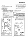
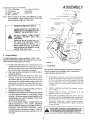
ASSEMBLY
Unpack Tractor
a
B
Take items out of box The box contains the items
shown below
b
Cut down four comers of the carton with a utifity
knife and fold down sides
c
Disengage Parking Brake
Place steering wheel adapter on upper steering
shaft.
With front wheels pointed straight ahead, place
steering wheel on steering wheel adapter Bars of
steering
wheel
should
point straight
across
tractor
Place 2- I/4" diameter washer on upper steering shaft and install a 1/2" Iocknut (washer and
Iocknut found in bag of parts). Tighten secure
ly.
9
10
Install
Steering
Wheel
1. Slide upper steering
shaft over lower steering
shaft until bolt holes line up with slots in lower
steering shaft (Fig, 11.
2
Use two hex bolts 3/8 - 16 x 1-1/4 and two
Ioeknuts 3/8 - 16 to retain upper steering shaft
to lower steering shaft, Tighten securely.
3 Position Steering Sleeve over steerinfi shaft
assembly.
4 For easier assembly,
tilt tube towards
front of
tractor.
5 Place bottom of Steering Sleeve over two front
prongs on steering bushing.
6 Squeeze the two steering sleeve retainers inward
to allow Steering Sleeve to pass over retainers
7.
t I
Snap
insert into
steering
f
Remove plastic on tractor hood
Raise attachment lift handle.
g
Roll Tractor
e
off skid
Be careful
wheel
of staples
in skid
The operation of any tractor can result In
foreign objects thrown In to the eyes, which
can result In severe eye damage. Always
wear safety glasses or eye shields before
startlngyourtractorandwhllemov/ng.
We
recommend Wide Vision Safety Mask for
over the spectacles or standard safety
glasses, available at Sears Retail or Cata.
log Stores.
Push Steering Sleeve down aligning notch on
Steering Sleeve with tab on steering bushing.
Parts
Bag
Contents
Not
Shown
Full
Size
IIIHtlillllIlilllilllllltllltlii!lillillilliilllll
121 Battery
Carriage
Bolts
Terminal
15" Slope Instruchon
. 1/4 ° 20 x 7 , t/2
Guard
Sheet
12) Keys
@
ring
o,Nn_l
b
c
d
steotln_
b#ltet¥
bmffoty
wheel
acid
l
g
h
l_atfs
Wheel
Adapter
5 mttt_at
bag
steel;rig
51o8v#
uppr, t sleeting
_hlH!
Battery Caps
L And Instructions
Steering
Wheel
Insert
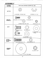
ASSEMBLY
A SSEMBL Y
L OCA TION
PARTS
BAG
CONTENTS
SHOWN
FULL SIZE
BA TTER Y
12l Lockwasher,
I/4
Int/Ext
Tooth
(2) Wing Nut - 1/4 - 20
©
BATTERY
TERMINALS
(21 Hex Bolt, I/4 - 20 x 3/4 _'_
{2) Washer
9/32
(2) Lockwasher 1/4
x 5/8 x 16 Ga.
©
121Flex Nut, 1/4 - 20
©
SEAT
(J) Lockwasher 1/2
(1) Hex Bolt, 1/2- 13 x 1
Grade5
(1) Washer 17/32 x 1-3/16
x 12 Ga,
(1) Shoulder Bolt 5/16 - 18
(I) Washer 15732x I x 16 Ga
UPPER
STEERING
SHAFT
llllllllllllllllllllllJ
(2) Hex Bolt 3/8- 16x I. 1/4
©
(2) Flex Locknut 3/8- 16
©
STEERING
WHEEL
111Locknut, 1/2-20
"" Dia, Washer
6
To assemble tractor you will need
(2) 7/16" Wrenches
Tire Pressure Gauge
(1) 1/2" Wrench
Screwdriver
(21 9/16" wrenches
Utility Knife
(tl 3/4" wrench
NOTE:
2
RIGHT HAND (RH) AND LEFT HAND (L H ) ARE
DETERMINED
FROM OPERATOR'S
POSITION
WHILE SEATED ON THE TRACTOR
STEERING
1/4
DIA
WHEEL
STEERING
ADAPTER
WHEEL
WEAR EYE AND FACE SHIELD
UPPER
STEERtNG
SHAFT
WASH HANDS OR CLOTHING IM MEDIATELY IF ACCIDENTALLY IN
CONTACT WITH BATTERY ACID
SLEEVE
DO NOT SMOKE; FUMES FROM
CHARGED
BATTERY ACID ARE
EXPLOSIVE
STEERING
SLEEVE
RETAINER
SPRING
READ THE INSTRUCTIONS INCLUD
ED WITH THE BATTERY VENT
CAPS IN THE BAG OF PARTS
ALWAYS WEAR GLOVES, CLOTHING
AND GOGGLES TO PROTECT YOUR
HANDS, SKIN AND EYES.
!RING
SHAFT
STEERINI
BUSHING
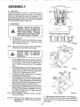
2.
Prepare Battery
Flll and charge battery (before installing) NOTE SEE
DETAILED INSTRUCTIONS PACKAGED WITH BATTERY
VENT CAPS FOUND IN BAG OF PARTS
a
b.
c
d
e.
L
FIGURE
Fill each cell with battery acid Add the acid until it
reaches the bottom of the vent tubes (Fig 3) DO not
add the acid beyond this level or the additional acid
can come out when the battery is charged
After cells are filled, tilt battery from side to side to
release air bubbles
Allow battery to stand and settle for at least thirty
minutes
If the level of acid falls below the point
described in step (a), add more acid until the correct
level is reached Instal/the battery caps, found in the
bag of parts, to cover the vent tubes Wash the top of
the battery with water to remove any acid, then wipe
dry.
Check battery case for leakage to make sure that no
damage has occured in handling.
Neutralizeexcessbatteryacidfordispesalbyadding
it to four inches of water in a five gallon plastic
container. Stir with a wooden or plasticpaddle while
adding baking soda until the addition of more soda
causes no more foaming_
Use a 12 volt battery charger Charge battery at a
rate of 6 amperes for I hour NOTE: OBSERVE
SAFETY PRECAUTIONS, LISTED IN BOX ABOVE,
REQUIRED FOR BATTERY CHARGING
Check
3.
1
STEERING
SLEEVE
RETAINER k
SPRING
Install Seat.
Seat position should be adjusted forward or backward so
that the operator can comfortably reach Clutch/Brake
Pedal and safely operate tractor
Place seat on seat
screw, Iockwasher
2) Screw shoulder
(Fig 2) Machine
washers found in
on page 6)
pan Screw hex head
and flat washer into
bolt and flat washer
screw, shoulder bolt
bag of parts (shown
b
Ttghten shoulder
1/2"" wrench
bolt
C,
Tlghten machine
screw,
Iockwasher
washer using a 1/2"" wrench
d
Place seat in operating position
Sit on the seat
and press clutch/brake
pedal all the way down If
operating pos/tion is not comfortable, adjust seat
e
To ad/ust Raise seat Loosen machine
screw
Sfide seat to desired position
Tighten machine
screw securely
a,
the acid level after the battery is charged If the acid
has fallen below the correct level, add distilled or iron
free water
I_
7
and fiat
washer
machine
seat (Fig
into seat
and flat
full size
using
and
WASHER MUST BETIGHTENED
SECUREMACHINE
LY
TO PREVENT
SCREW-LOCKWASHER-FLAT
MOVEMENT
OF SEAT.
a
flat
J
Y
_{At
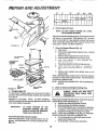
4. Check Tires
Check the air pressure in the tires Tires with too much air
pressure will cause the unit to ride rough
The wrong air
pressure will also keep the mower from cutting level The
correct air pressure Is shown on the side of the tires If the air
pressure is not shown, set to pressures shown in the REPAIR
AND ADJUSTMENT section (page 141,
5.
PAN
_IAT
5HOULO[R
AOJU$1MENf
F|NDI_
BOLT
BOLt
0ATI|R
Y
T|R_INAL
Install Battery
•
ISATT|#V
T|RMINAL
_ATT|nY
FIGURE
BEFORE
INSTALLING
BATTERY,
REMOVE
METAL
BRACELETS,
WRISTWATCH BANDS, RINGS, ETC.
FROM YOUR PERSON. TOUCHING
THESE ITEMS TO BATTERY TERMINALS COULD RESULT' IN BURNS.
t"ltl
AWAy
!.::
L___J
V_[W
t3ATT|Ry
CAP
f
_
"
..,-_f_
a
b
.
VENT
BAI_IERY
TUBE
Lift seat (Fig 2)
Lower battery into fender well with battery tetmitlals
toward front of tractor (Fig 4). Make sure battery
rests in battery tray (Fig. 4),
VEL
CELL FIGURE 3
NOTE: BE SURE BATTERY DRAIN TUBE IS SECURELY
ATTACHED TO BATTERY TRAY DRAIN
NECTED
FIRST
TO
PREVENT
SPARKS
FROM
ACCIDENTAL
POSITIVETERMINALMUSTBECONGROUNDING
2
WASHER
NEGATIV£
TERMINAL
NEGATIVE
l
c.
Connect RED battery cable to positive (+) battery
terminal with hex bolt, flat washer, lockwasher and
hex nut (shown full size on pg 6) found in bag of
parts
Tighten securely with two 7/16" wrenches.
(Fig 4)
d
Connect BLACKgroundcable to negative (.) battery
terminal with remaning hex bolt, flat washer, lockwasher and hex nut (shown full size on pg. 6) found
in bag of parts. Tighten securely_ (Fig 4)
e. To prevent oorrosion, apply grease to the battery
terminals after installing cables.
f
Usingthekeyholeononesideofthebatterysupport
(Fig_ 5) slide battery bolt into frame key hole (head of
bolt down), Fasten the battery belt to the terminal
guard using internal/external lockwasher, wing nut,
(shown full size on pgo 6) as shown in Fig 5.
g, Assemble the remaining battery bolt to other side of
battery support and fasten terminal guard to it with
remaining internal/external Iockwasher and wing
nut, (Shown full size on pg 6). Tighten wing nuts
securely by hand (Fig, 5).
NOTE: KEEP TERMINAL ACCESS DOORS CLOSED
WHEN NOT IN USE
CAUTION:
BATTERy
TRAy
BATTERY
FIGURE 4
LOCKWASHER
6. Maintenance After First 2 Hours (Two Mowlngs)
Changing oil after the first two hours (ortwo mowings) will
help eliminate break4n residue which might be damaging to
your engine,
DO NOT START ENGINE UNTIL YOU HAVE
REVIEWED THE OPERATION SECTION OF
THIS MANUAL
8
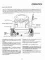
KNOW
YOUR
TRACTOR
READ THIS OWNER'S MANUAL BEFORE OPERATING YOUR YARD TRACTOR
operation,
you will achieve efficient
and peak performance
While reading the
your Yard Tractor to familiarize yourself with the location
of various controls
instructions
and safety precautions
thoroughly to insure proper functioning
of
to yourself and others Be sure to pay strlct attention
to all notes and cautions,
this manual for future reference
If you understand
the machine and sts
manual, compare the illustrations
w_th
and adjustments
Study the operating
your Yard Tractor and to prevent mlur_,
they are included for your safety
Save
Ignition
Light
Switch
Throttle/{
Attachment
Lift Lever
Clutch/Brake
Pedal
Clutch
Lever
Height
Adjustment
Knob
Gear
Shift
Parking
Brake
Lever
GEARSHIFT: Press the clutch/brake pedal down firmly and
move gear shift lever to desired speed
ATTACHMENT CLUTCH LEVER: Push lever up to engage
attachment. There will be an engine hesitation as the clutch
engages.
IGNITION: Place key in ignition and turn to the right to start
The switch spring returns from the start position
ATTACHMENT LIFT LEVER: Use the attachment rift lever
to raise and lower the attachment mounted to your tractor
Pull lever back slightly and push button, then move the lift
lever forward to lower attachment,
LIGHT SWITCH:
Turns the headlights on and off
PARKING BRAKE: To set the parking brake, push the
clutciVbrakepedalcomp/ete/ydown
Ho/dtheparkingbrake
lever in "Engaged"position and release pressure from pedal
C/utch/'orake pedal will remain in brake position.
CLUTCH/BRAKE PEDAL: The pedal has 2 functions; a
clutch and a brake. To engage the brake push the pedal
completely down.
THRO TTL EICHOKE CON TROL: Use the throttle
control
to increase or decrease the speed of the engine, and to
choke the engine for starting
Push lever to the r/ght
and forward
to choke
ATTACHMENT HEIGHT ADJUSTMENT KNOB: Use the
height adjustment knob to adjust the mower height, Withthe
attachment lift lever in the "up"position, turn knob clockwise
(,f'_ ) to raise cutting height and _ountercIockwise _"_
)
to lower cutting height
9
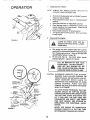
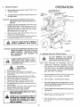
OPERATION
stopping
Your
T,.otor
NOTE:
AIR
a
b
c
d
e,
f
FUEL
TANK
/
2,
FIGURE 6
REMOVE KEY WHEN LEAVING
PREVENT UNAUTHORIZED
USE
TRACTOR
TO
Push clutch.brake pedal into furl "BRAKE" position
Keep your foot on pedal
Place attachment clutch lever in "DISENGAGED"
Position,
Move gear shift lever to "NEUTRAL"position.
Place parking brake in "ENGAGED" position and
release pressure from clutch/brake
Pedal should
rema#7 in "BRAKE" position
Move throttle control to "S" (slow) position
Tumignitionkeyto
"OFF"position Neverusechoke
to stop engin&
Preparing The Engine
/
VERSE YOUR TRACTOR
OPEN AREA.
IN A LARGE,
LEARN
TOSTART,
STOP
AND
REa_
This engine has been shipped filled with summer
weight oil (For cold weather operation see chart page
16). Check engine oil leveL Refer to REPAIR AND
ADJUSTMENT section ( page 16)o
Flit fuel tank (Fig. 6). Use fresh, clean, regular
unleaded gasoline, Capacity is 5 quarts,
,,,,,,,,
...........
FILL TO BOTTOM OF GAS TANK
FILLER NECK.
DO NOT OVERFILL.
WIPE OFF ANY SPILLED
OIL OR
FUEL. DO NOT STORE, SPILL OR USE
GASOLINE NEAR AN OPEN FLAME.
CAUTION:
MOWER
EXPERIENCE
INDICATES
THAT
ALCOHOL
BLENDED FUELS (CALLED GASOHOL OR
USING ETHANOL OR METHANOL) CAN ATTRACT
MOISTURE
WHICH
LEADS
TO
SEPARATION AND FORMATION OF ACIDS
DURING
STORAGE.
ACIDIC
GAS CAN
DAMAGE THE FUEL SYSTEM OF AN ENGINE
WHILE IN STORAGE.
BLAOE
POSITiUN
HEADLIGHT
TO AVOID ENGINE PROBLEMS, THE FUEL
SYSTEM SHOULD BE EMPTIED BEFORE
STORAGE FOR 30 DAYS OR LONGER. DRAIN
THE GAS TANK, START THE ENGINE AND
LET IT RUN UNTIL THE FUEL LINES AND
CARBURETOR
ARE EMPTY. USE FRESH
FUEL NEXT SEASON_ SEE STORAGE INSTRUCTIONS
FOR ADDITIONAL
INFORMATION,
THROTTLI_
CONTROL
LEVER
NEVER USE ENGINE OR CARBURETOR
CLEANER PRODUCTS IN THE FUEL TANK
OR PERMANENT DAMAGE MAY OCCUR.
10
3.
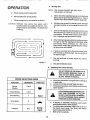
OPERATION
Starting The Engine
a
Move throttle controllever (Fig 7) past "FAST" to the
"CHOKE" position
HEIGHT
ADJUSTMENT
KNOB
b_ Tumignitionkeyto'START"andreleasekeyassoon
as engine starts
CAUTION:
ff engine does not start after four or five tries, move
throttle control lever to "FAST"position, wait a few
minutes and try again, ff the engine does not start
after four or five more tries, see the TROUBLESHOOTING Chart (page 25)
d
After the engine starts move throttle control lever
slowly to the "SL 0 W" position
To start a hot engine move the throttle control lever
to a position between "FAST" and "SLOW _
[
LIFT
SUBSTANllAL
3E
FIGURE8
4.
I I,
A
Mower
WITHOUT
DEFLECTOR
SHIELD
DO NOT THE
OPERATE
THE MOWER
(DISCHARGE GUARD) IN PLACE,
NOTE: THIS TRACTOR
IS EQUIPPED
WITH AN
OPERATOR
PRESENCE
SENSING SWITCH
ANY ATTEMPT BY THE OPERATOR TO LEAVE
THE SEAT WITH THE ENGINE RUNNING AND
THE ATFACHMENT CLUTCH LEVER ENGAGED
WILL SHUT OFF THE ENGINE
TO CAUTION
AVOID INJURY
Read owner's
manual
Know location
and function
of all controls
Keep guards, safety shield and switches
in place
and working.
Remove objects that can be thrown by blades
Do not mow when children and others are around
Never carry children or passengers
Always
look behind machine before backing
Do not mow where machine can tip or slip
If machine stops going uphill, stop blades and back
slowly down.
Be sure blades and engine have stopped
before
placing hands or feet near the blades
Remove key when leaving machine
MAKE SURE PARKING
TRACTOR SECURE.
Operating Your Lawn Tractor&
,_
FOOT-
WEAR
ANDTHAT
AVOID
LOOSE
FITTING
CLOTHING
COULD
GET CAUGHT
IN MOVING PARTS
10_
RUNNER
GUARD
DO NOT ADD ADDITIONAL WEIGHT TO THE
TRACTOR OTHER THAN THE OPTIONAL
WHEEL WEIGHTS.
EXCESSIVE WEIGHT
MAY OVERLOAD
AND DAMAGE
THE
TRANSMISSION
WEAR
POSITION
LIFT LEVER
"LOWEST"
POSITION
READTHE OPERATING
"SAFETY RULES"
BEFORE
YOURCAREFULLY
MOWER.
ALWAYS
4.
5_
6,
7,
8_
9_
LIFT LEVER
"HIGHEST'
LEVER
H
CAUTION:
1
2
3
POSITION
DO NOT RUN STARTER CONTINUOUSLY
FOR MORE THAN FIFTEEN SECONDS PER
MINUTE
c,
e
ATTACHMENT
CLUTCH
LEVER "DISENGAGED'
POSITION
ATTACHMENT
CLUTCH
LEVER 'ENGAGED'
a,
Move the attachment lift leverto lhe high position and
adjust height of cut to mid range See Fig 8
b
Start the engine
c
Move the throttle lever to mid range position, Select
a low ( l st or 2nd) gear until you become more familiar
with the operation of the unit.
d,
Slowly release clutch brake pedal and proceed to the
mowing area
e,
Stop the umt. then select a mowing
Speed Selection
Guide. page 12)
f.
Move throttle
lever to half throttle
and slowly
move attachment
clutch lever to engaged pes/tlon. Ft_7 8
(See Starting the Engine)
BRAKE WILL HOLD
NEVER PLACE YOUR HANDS OR FEET IN
OR UNDER ANY POWERED ATTACHMENT
OR NEAR ANY MOVING PART WHILE
TRACTOR OR ANY POWERED ATTACHMENT IS RUNNING.
11
speed
(See
5.
OPERATION
NOTE:
g
Slowly release clutch brake pedal
h.
Move throttle lever to fast position.
i
Observe height of cut and readjust as desired
CAUTION:
TIRE CHAINS CANNOT BE USED WITH
THE MOWER ATFACHED,
a_ Mower should be adjusted properiy front to back and
side to side fof good mowing performance,
Refer to
REPAIR AND ADJUSTMENT section _page 22L
b,
BEFORE YOU MOVE THE GEAR SHIFT
LEVER, COME TO A COMPLETE STOP_ FAILURE TO DO SO CAN RESULT IN GEAR BOX
DAMAGE
C.
F
T
Mowing Tips
i
I1
Use the runner on the RoH. side as a guide; the blade
cuts approximately an inch outside the runner (Fig
Drive so that clippings are discharged onto the area
that has been cuL Have the cut area to the right of
the machine, This willresult in a more even distribution of clippings and more uniform culling.
d_
When mowing large areas (Fig, 9), start by turning to
the right so that the clippings will discharge away
from shrubs, fences, driveways, etc. Alter Iwo or
three rounds, mow in the opposite direction making
left hand turns until finished,
e.
ff grass is extremely tall, it should be mowed twice
The first time cut relatively high; the second time to
the desired height,
f,
The left hand side of mower should be used for
trimming.
FIGURE
9
g,
6.
See Speed Selection Chart,
Operating
&
The Tractor On Hills
DO NOT DRIVE UP OR DOWN HILLS
WITH SLOPES GREATER THAN 15 °
AND DO NOT DRIVE ACROSS ANY
SLOPE. REFER TO PAGE 51.
....,,,,,
--
SPEED
FUNCTION
SELECTION
GEARSHIFT
GUIDE
a.
THROTTLE
b.
,,,,,,,,
Normal
Mowing
2 or3
Heavy Mowing
1 or2
Snow Blowing
1
c,
2
Transport
4-6
ff slowing is necessary, move throttle control lever to
slower position,
LEAVE ENOUGH ROOM WHEN STOPPING AND STARTING TO ALLOW
SLIGHT TRACTOR ROLL DOWNHILL
AS CLUTCH-BRAKE PEDAL MOVES
THROUGH CLUTCH POSITION.
FAST
i,,,,,,,,,
Snow Blade
Move gear shift lever to "Isr" gear before starting up
or down hills.
AVOID STOPPING OR SHIFTING ON HILLS
d_ If stopping is absolutely necessary, push clutch/
brake pedal quickly to brake position.
e. To restart tractor movement, make sure tractor is in
the lowest speed range ('1st" Gear) and release
clutch-brake pedal SL OWL Y.
L
Make all turns gradually,
SLOW FAST
12
To keep your tractor running better,
longer,
perform necessary
service using the folio wing
maintenance
schedule:
BEFORE MAKING ANY INSPECTION,
ADJUSTMENT,
OR REPAIR:
1. PUSH CLUTCH/BRAKE
PEDAL
COMPLETELY
DOWN.
2_ MOVE GEAR SHIFT CONTROL
LEVER TO NEUTRAL POSITION,
3, PLACE PARKING BRAKE IN "ENGAGED" POSITION.
REMOVE
FOOT FROM PEDAL.
4. DISENGAGE
ATTACHMENT
CLUTCH LEVER.
5, SHUT OFF THE ENGINE.
6, MAKE ABSOLUTELY
SURE THE
BLADES
AND
ALL
MOVING
PARTS
HAVE
COMPLETELY
STOPPED.
7. DISCONNECT THE SPARK PLUG
WIRE
FROM
THE
SPARK
PLUG
AND
KEEP
WIRE
AWAY
FROM
THE
SPARK
PLUG
TO
PREVENT
INJURY
FROM ACCIDENTAL
STARTING,
BE CAREFUL TO AVOID TOUCHING HOT ENGINE OR MUFFLER
COMPONENTS,
With Every Mowing
1
Make sure all nuts on bolts are tight and cotter pins and
2
3
retainer springs are secure.
Observe all safety precautions
Keep tractor well lubricated (refer to page 24)
SERVICE
SERVICE
RECORD
(Enter Date Maintenance
I
SCHEDULE
RECORD
Fill in dates as you (_mplete regular service
Performed)
FIRST
2
HOURS
EVERY
EVERY
EVERY
5
25
50
HOURS
HOURS
HOURS
EVERY
tO0
HOURS
!
Blades - sharpen
€
Brake Adjustment
€
Check Battery
€
Change Engine OII
Check Engine O11level
Clean Air Cleaner
€
€
Element
Check Muffler
i
Clean Air Screen
Clean Front Grill
Lubricate
Tractor
_w
Replace
€
Spark Plug
Replace Air Cleaner
Element
€
C!neck Tire Pressure
13
AND ADJUSTMENT
BRAKE
OPERATING
BRAKE
ROD
JAM NUT
ARM
NUT
A
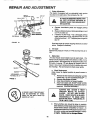
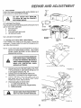
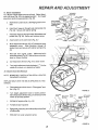
1. Brake Adjustment
This tractor is equipped with an adjustable brake system
mounted on the fight side of the transaxle (Fig, I0)_
L
IF TRACTOR REQUIRES MORE THAN
SIX FEET STOPPING DISTANCE IN
HIGHEST GEAR, THEN BRAKE MUST
BE ADJUSTED.
a.
Depress clutch/brake pedal and engage parking
brake.
b. Measure distance between brake operating arm and
nut "A'on brake rod.
c_ ff distance is other than 1-1/2" disengage parking
brake, loosen jam nut (Fig. I0) and turn nut ",4" until
distance becomes I - 1/2" Retightenjam nut against
Nut "A".
(WITH PARKING
_AKE ENGAGEO|
DISC
BRAKE
FIGURE
1o
Road test tractor for proper stopping distance as stated
above. Readjust if necessary,
2. Tire Care
Maintain tire pressure in front at 14 PSI and rear tires at 12
PSi.
3. Blade Care
For best results mower blades must be kept sharp. The
blades can be sharpened with a few strokes of a file, or on a
grinding wheel. We suggest they be sharpened after every
25 hours of mowing. Do not attempt to sharpen while on
mower. If you mow in sandy soil check the blades after each
two redwings. The sand wears the blade away rapidly.
IANDREL
ASSEMBLY
FLANGES
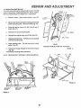
a° Blade Replacement
Raise mower to highest position to permit access to
blades.
1. Remove the hex head belt, Iockwasher and flat
washer (Fig. 1 I) (turn counterclockwise)(/'-"_).
2. Remove and discard old blade.
3. Clean top and bottom of mower housing.
4. Install new blade with SHARP EDGE DOWN
and secure withflat washer, Iockwasher and hex
head bolto TIGHTEN SECURELY.
ALWAYS "'USE GRADE
5 HEAT
TREATED
BOLTS TO ATTACH
BLADES.
DO NOT USE PLATED
BOLTS. CHECK BOLTS IN BLADES
OCCASIONALLY
TO MAKE SURE
BOLTS ARE TIGHT. TORQUE BOLTS
TO 30 - 35 FT,- LBS,
A GRADE 5 HEAT TREATED BOLT
CAN BE IDENTIFIED BY THREE
LINES ON THE BOLT HEAD AS
SHOWN AT LEFT_
b.
When grinding, care should be taken to maintain
blade balance and the blade should be checked for
proper balance before reinstallation on mower. An
unbalanced or bent blade willcause excessive vibration when running, and eventual damage to mower
DrenCh.
14
eramm KIb =W,
ADJUSTMENT
C
4.
To check blade balance, drive a nail into a beam or
wall. Leave about one inch of the straight nail
exposed. Place center hole of clean blade over the
head of the nail (Fig 12) NOTE: CENTER HOLE
OF BLADE ON NAIL, IF BLADE IS PROPERLY
BALANCED, BLADE SHOULD REMAIN IN POSITION SHOWN IN FIG. 12 IF EITHER END OF THE
BLADE MOVES DOWNWARD,
BLADE IS NOT
BALANCED. SHARPEN THE HEAVY END UNTIL
BLADE IS BALANCED
/"OLE "
lit
BA TTERY CARE
FIGURE
12
Check Battery
a
b
c
d
e
Battery acid solution levelin each battery cell should
be even with bottoms of vent tubes in cells (Fig 13)
Add ONL Y distilled or iron free water if necessary
NOTE: DO NOT OVERFILL,
LEAD-ACID
d
VI[W
BATTERY
CAP
BATTERIES
UQUID
LEVEL
GENERATE
EXPLOSIVE GASES. KEEP SPARKS,
FLAME AND SMOKING MATERIALS
AWAY FROM BATTERIES. ALWAYS
SHIELD YOUR EYES AROUND
BATTERIES.
c,
AW_,Y
Keep battery and terminals clean,
Keep battery bolts tight
Keep vent caps tight and small vent holes in caps
open.
Recharge at 6 amperes for 1 hour if necessary,
Clean Battery and Terminals
Corrosion and dirt on the battery and terminals cause the
battery to "leak'power and hinders the operation of the
charger,
a,
b
£_t'i
Remove terminal guard,
Disconnect BLACKbattery cable, then RED battery
cable, and remove battery from tractor,
Washbatterywithfourtablespoonsofbakingsodato
one gallon of water, NOTE: BE CAREFUL NOT TO
GET THE SODA SOLUTION INTO THE CELLS,
Rinse the battery withplain water, dry and reinstallon
tractor,
eo Clean terminals and battery cable ends with wire
brush until bright,
f,
Replace battery cables, connecting RED battery
cable to positive terminal first, then BLACK battery
cable to negative terminal Coat terminal connections with vasoline after installation of cable_.
g
Replace terminalguard
15
REPAIR AND ADJUSTMENT
32 °
6.
FUEL FILLER
CAP
60 °
80 °
tO0 °
Check Engine 011 Level
NOTE: DO NOT CHECK ENGINE
WITH ENGINE RUNNING.
OIL LEVEL
Several minutes after stopping engine, check engine oil level
with tractor on level ground. Wipe dipstick (Fig. 14) clean,
screw il down tight for a few seconds, remove and read oil
level If necessary, addoiluntil"FULL"markisreached.
(See
chart above). NOTE: DO NOT OVERFILL.
FIGURE
14
7.
AIR CLEANER
COVER
AIR CLEANER
ELEMENT
SUPPORT
FOAM
Clean Air Cleaner Element (Fig. 15)
am Open hood.
b. Removetwoscrewsfromaircleanercover.
Liftoffair
cleaner (Fig. 15)
c. Remove screen spacers from foam element.
do Remove foam element from air cleaner body.
e.
Wash foam
element
water to remove dirt
in
liquid
detergent
and
L
g.
Wrap foam element in cloth and squeeze dry.
Lightly coat foam with engine oil
Squeeze in
rag or towel to remove excess oil
Do t?ot saturate
ho Replace foam element and replace cover on air
cleaner body.
When assembling make certain the lip of the foam element
extendsoveredgeoftheaircleanerbody.
Thefoamelement
lip will form a protective seal
NOTE: NEVER RUN ENGINE WITH AIR CLEANER REMOVED,
ELEMENT
AIR
CLEANER
FIGURE 15 BODY
AIR
CLEANER
8.
GASKET
5. Change Engine 011
The best time to change engine oil is at the end of a day's
operation when all dirt and foreign materials are suspended
in the hot oil.
ALWAYS
WEAR EYE AND
PROTECTION WHEN USING
PRESSED AIR.
Capacity is I-1/2 quarts. NOTE: DO NOT OVERFILL.
Dipstick assembly most be securely tightened into tube at all
times when engine is operating.
IMPORTANT:
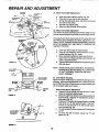
Clean Air Screen and Engine Cooling Fins
FACE
COM-
Keep Engine Cooling Fins free of dust, dirt and oil to prevent
Engine damage from overheating iFig_ 16),
a. Remove four Bolts from Blower Housing.
b, Remove Screws from Starter Housing.
c, Pull Oil Filler/Dipstick out of crankcase ff clearance
is requirado Cover opening to prevent entry of dirt.
d. Pull blower housing up and away from starter,
NOTE: LEAVE AIR CLEANER IN PLACE TO PREVENT
DEBRIS FROM GETTING INTO CARBURETOR_
e.. Use compressed air or stiff bristle brush to thoroughly clean Engine Fins.
f. To reassemble, reverse above procedure
TO AVOID DAMAGE TO THE
STARTING SYSTEM, USE SAE
5W30 OIL WHEN THE TEMPERATURE FALLS BELOW 32 °.
Recommended SAE Viscosity Grades
Determine temperature range expected before next oil
change_ All oil must meet A,P.L service classification SD,
$E or SF,
16
FtEPAIR AND ADJUSTMENT
9. Check Muffler
Inspect and replace damaged muffler and/or deflector as it
could create a fire hazard and/or damage.
BOLTS
BOLTS
l
CYLINDER OR FINS AS CONTACT
DO NOT
TOUCH
MAY
CAUSE
BURNS,HOT MUFFLER,
_
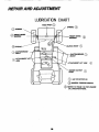
10. Lubricate Pivot Points
Place several drops of SA E 30 oil at points where parts move
against each other, especially:
a
Front axle pivot
b
Hood hinges
c
Foot pedal shaft (both ends)
d
Lift shaft (both ends)
I_R
See Lubrication Chart page 24
STARTER
HOUSING
ENGINE
COOLING
FINS
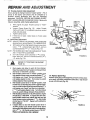
11. Starting your Tractor With a Weak Battery
If your battery is too weak to start the engine, it should be
recharged. If "jumper cables" are used for emergency starting, follow this procedure:
NOTE:
U R E 16
YOURTRACTORISEQUIPPED
WlTHA12VOLT
NEGATIVE GROUNDED SYSTEM
THE OTHER
VEHICLE MUSTALSOBEA12VOLTNEGATtVE
GROUNDED SYSTEM
LEAD-ACID BATTERIES GENERATE
EXPLOSIVEGASES.
KEEPSPARKS,
FLAME AND SMOKING MATERIALS
AWAY FROM BATTERIES. ALWAYS
WEAR EYE PROTECTION
WHEN
AROUND BATTERIES.
a.
Connect each end of the RED cable to the POSI-
br
TIVE (+) terminals of each battery (taking care not
to short against chassis), (Fig. 17)
Connect one end of the BLACK cable to the
c,
d
FIGURE
NEGATIVE (-) terminals of fully charged battery,
Connect the other end of the cable to the L H
side panel bolt (Fig. 18) NOTE: KEEP AWAY
FROM GAS TANK AND BATTERY
Disconnect cables in reverse order:
BRAKE
"ENGAGED
1_ L.Ho Side Panel Bolt (Fig, 18)
2_ Negative terminals of fully charged battery
3
Positive terminals
A
17
;AGED
CLUTCH*'
POSITION
• POSITION
I
DO NOT USE YOUR TRACTOR BATTERY TO START OTHER VEHICLES.
I
I
GEAR
LEVER
rCLUTCH/BRAKE'"
POSITION
t7
CLUTCHIBRAKE_
'*DRIVE"
_, POSITION
SHIFT
//
_1'/
/
•
_
FIGURE
18
AND ADJUSTMENT
12o Throttle Control Cable Adjustment
Never attempt to change maximum engine speed This is
preset at the factory and should only be changed by a
qualified service
technician
who has the necessary
equipment
CAUTION: BEFORE ANY ENGINE ADJUSTMENT, MAKE SUREAIR CLEANER IS CLEAN. RemoveAir
Cleaner Assembly, while making adjustments_
a
b
c
iDLE
STOP
DO NOT
ADJUST
With engine off, place Throttle Control in "FAST"
position,
Loosen Clamp Screw (Fig 19)
Adjust Throttle
Cable until holes "A "ate aligned in go vemor control
plate and slide plate
Tighten clamp screw
If holes do not align, repeat steps in throttle cable
adjustment
13. Carburetor Adjustment
NOTE: ADJUST THROTTLE CONTROL CABLE BEFORE
MAKING ANY ADJUSTMENT TO CARBURETOR
a
With engine off turn high speed mixture screw clockwise ( _
) closing finger tight ONLY, and turn
counterclockwise ( _-_'_) 1-1/2 turns (Fig 19)
NO TE_ THE SCREW SEA T MA Y BE DAMAGED B Y TURNING IT TOO FAR CLOCKWISE
IDLE
MIXTURE
SCREW
THROTTLE
d
b
_
IDLE
MIXTURE
ADJUSTMENT
IDLESPEED
SCREW
HIGH SPEED
MIXTURE
SCREW
HOSE
CLAMP
SLIDE
PLATE
PLATE.
GOVERNOR
CONTROL
FUEL
FILTER
Turn idle mixture screw clockwise (f'_)
closing
finger tight only, and turn counterclockwise (._'.)
1-V2 turns (Fig 19).
REFER 10o
TO "STARTING
PAGE
HOSE
CLAMP
FIGURE
19
THE ENGINE"
Co Start engine and allow to warm for five minutes,
Make final adjustment with engine running and Gear
Shift lever in "NEUTRAL" positlon,
do With throttle control lever in "FAST" position, turn
high speed mixture screw counterclock wise (.'_'-_ )
until engine runs "rough"then turn clockwise (f-_)
until engine begins to miss° Turn screw to a point
midway between these positions.
e, With throttle control lever in "SLOW"position,
hold
throttle lever so that idle stop screw is against carburetor, turn idle mixture Screw counterclockwise ("_')
until engine runs "rough" and then turn clockwise
( F-_ ) until engine begins to die. Turn idle mixture
screw to a point midway between these positions.
f
Withthrottlecontmlleverin"SLOW"position,
engine
should idle at 1750 RPM. ff engine idles too slow,
push throttle control lever above idle and turn idle
speed screw one turn clockwise ('-_).
Set throttle
control lever at "SLOW'. Repeat until satisfactory
idle is attained.
g. ff engine Idles too fast with throttle control lever in
"SLOW" position push throttle control lever above
idle and turn idle speed screw one turn counterclockwise (,_-"_),
Set throttle control lever at "SLOW",
Repeat until satisfactory idle is attained.
14. Replace Spark Plug
Replace spark plug at the beginning of each mowing season or every lOO hours, whichever comes first. Gap shou/d
be set at 0.030 inch (Fig. 20).
_,
tm
•
_
'"
,/
/. *1_) 4 "
.030
•
FEELER
GAUGE._..
FIGURE 20
18
AND ADJUSTMENT
15. Motion Drive Belt Removal
Thetractordrivebeltmaybereplacedwithouttools
Parkthe
tractor on level area, Engage parking brake, NOTE: A BELT
INSTALLATION DECAL IS UNDER LEFT FOOTREST
ao Remove mower,
(See mower
section,
ENGINE
PULLEY
page 20),
b.
Remove two retainer springS from be# guide bracket
below transaxle pul/ey. Remove bracket (Fig. 21)o
c.
Swing belt guides
tractor (Fig.. 21).
cL
Roll bell over top of transaxle pulley,
e.
Roll bell over engine pulley and off idler (Fig. 22).
L
Release parking brake° Puff belt as far as possible
over top of clutch pulley..
g.
Reset parking brake.
pulley (Fig.. 22).
/
ELT
INSTALLATION
DECAL
CLUTCH
away from belt, toward rear of
LH. SIDE
BELT
Pull belt over top of clutch
GUIDE
REAR
VIEWED
FROM BOTTOM
h.
Pull belt out through shift gate to remove from tractor
(Fig. 23).
Install belt by reversing above procedure.
OF TRACTOR
FIGURE
22
BELT
NOTE: REPLACE ONLY WITH BELT LISTED IN MANUAL
BELT
GUIDE_
TRANSAXLE
PULLEY
SHIFT GATE
_GURE
RETAINER
SPRING
FIGURE
f l
BELT GUIDE
BRACKET
RETAINER
SPRING
21
19
23
AND ADJUSTMENT
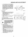
16. Fuse Replacement
Replace with 30 amp automotive - type plug-in fuse.
17. Hood Removal
SCREW
FIGURE
a.
To raise hood, lift at rear of hood
b.
To remove hood, grill and side panels, raise hood
and loosen one screw on each side panel
(This
screw remains in the side panel) (Fig 24)
c
Unsnap headlight connection
d
Stand in front of tractor. Grasp hoodand tilt forward
and lift off (Fig, 25).
e.
To reinstall, reverse above pmcedura.
18. Mower Removal
24
a_
HEADLIGHT
CONNECTION
FIGURE 25
Remove mower bell per instructions under "Mower
Drive Belt Removal" through step(c).
b.
Remove retainer spring from clutch rod; pull clutch
rod out of clutch bracket, (Fig 26)
c.
Puff retainer springs out of rear suspension trunnions. Remove rear suspensions trunnions from lift
brackets (Fig. 26).
d
Pull retainer spring out of rear hinge pin_ Remove
rear hinge pin
e.
Pull retainer spdng out of front hinge pin
front hinge pin (Fig,26)
Remove
f_ Use lift lever to raise suspension arms, Slide mower
out from under tractor°
RETAINER
SPRING
R_H,
SUSPENSION
ARM
NOTE:
RETAINER
SPRINGS
HINGE
PINS
REAR
SUSPENSION
TRUNNIONS
LIFT
BRACKET
_URE
(Fig 25)_
26
2O
IF AN ATTACHMENT OTHER THAN THE MOWER
DECK IS TO BE MOUNTED ON THE TRACTOR,
THE L.H. AND R.H. SUSPENSION ARMS (FIG. 26)
SHOULD BE REMOVED FROM TRACTOR.
REPAIR AND ADJUSTMENT
19. Mower Insta#atlon
Your Mower installs without the use of tools Raise Attachment Lift Lever (Fig 27) to its highest position
Turn height
adjustment knob to lowest position (Fig 28)_
"HIGHEST
_
POSITION
PL, UNGE
N_
a
Slide Mower under tractor, discharge guard to RH
Side
LIFT
"DISENGAGED
_
os,T,ON"
Install front hinge pin through axle and parallel rink
(Fig_ 29) Secure with retainer spring
c
Installrear hinge pin through mower rift brackets and
parallel link (Fig 29), Secure with retainer spring,
d
Install clutch rod in clutch lever (Fig 29 )
LIFT
LEVER
CLUTCHLEVER._._._ ._"_
ATTACHME
b
R
LEVER
j '
-'--_
__W
,
"
.:'.
_
_1 /"t/
P OSITION
)
FIGURE 27
e_
Move Attachment rift lever (Fig 27) forward to lower
suspension arms
Slide trunnions through lift
bracket holes and secure with retainer spdngs (Fig
26)
\
ENGINE
PULLEY
3ELT
_
\\
f
Roll belt over engine pulley.
Make sure belt is
inside belt guides (Fig_28)_ See beit drive schematic
decal on mower housing
g
Use Attachment lift lever (Fig 27) to raise mower
h
Turn height adjustment knob clockwise (,_".)
middle of #s travel, or to desired cut height.
to the
/
20_ Mower Drive Belt Removal
(
NOTE: MOWER BELT INSTALLATION DECAL LOCATED
ON MOWER HOUSING
REPLACE ONLY WITH THE BELTS SPECIFIED
MANUAL
a
IN THIS
Place attachment clutch lever in "Disengaged"position (Fig 27)_
FIGURE
b
Turn height adjustment knob to lowest position
Move Attachment lift lever (Fig 27) forward to lower
mower to its lowest position_
CLUTCH
ROD
RETAINER
SPRING
PARALLEL
LINK
_
FRONT
AXLE
28
RETAINER
SPRINGS
\
c
Roll belt off engine pulley (Fig 28)
d
Pull bell off beth mandrels
e,
Spring bell guide away form idler pulley and pull belt
off idler pulley
t
Slide belt from under extension spring
REAR
HINGE
PIN
FIGURE 29
21
REPAIR AND ADJUSTMENT
21. Mower Drive Belt Replacement
a.
b.
c.
d
e.
Slide belt under extension spring (Fig. 30).
Place belt on rear side of beth mandrels_
Spring idler belt guide down and place belt around
rear side of idler pulley°
Rofl belt over engine pulley,
Make sure belt is inside aft belt guides
22. Mower Drive Belt Adjustment
Your tractor has been manufactured with the ability to readjust the mower belt drive to provide you with longer belt life.
If the attachment clutch lever travels 3-1/2" up the slot in the
dash before spring resistance is evident, adjustment is necessary. NOTE: CHECK FOR PROPER SPRING TENSION
WITH THE ENGINE OFF AND THE LIFT LEVER IN THE
HIGHEST POSITION.
a.
b.
Lower the mower deck for easier access.
Using (2) 1/2 wrenches, remove the bolt, nut & Dshaped washers (Fig° 30 - Inset).
Co Move extension spring from lower end of slot to
upper end in mck shaft assembly and install belt, nut
& the D.shaped washers.
d. TightenbeltandnuttosecuretheD-shapedwashers
(flat side down).
BOLT
\
FIGURE
LIFT
30
NOTE: WHEN INSTALLING A NEW BELT, EXTENSION
SPRING MUST BE RETURNED TO LOWER END
OF SLOT (ORIGINAL POSITION) ON ROCK
SHAFT ASSEMBLY.
LEVER
PLUNGER
23, Level Mower Housing
Adjust the mower while tractor is parked on level ground or
driveway. Make sure tire pressures are 14 PSI in front tires
and 12 PSl in rear tiras, ff tlres are over or under inflated, you
will not properly adjust your mower.
SIDE-TO,SIDE
J
°Fc F /
GROUND_
uNz
_
ADJUSTMENT
,_-_ BOTTOM
--
:271-o.oo.o
_A
UNE
Side-to.Side Mower Adjustment
a. Depress lift lever plunger and use lift lever to raise
mower to maximum cutting height.
b. Measure he_ht from bottom of curl to groundline at
fmnt of mowero Distance "A"should be the same on
beth sides (Fig. 31).
c. If distance "A"needs to be changed, snap out access
hole cover on L.H. side above footrest° Use 9/16"
wrench on nuts "B" and "C" at side-to-side adjustment trunnion (Fig. 32).
d. To raise left side of mower, loosen nut'B"and tighten
nut "C'.
e. To lower left side of mower, loosen nut "C" and
tighten nut "B'.
FIGURE31
SIDE.TOotIDE
ADJUSTMENT
TRUNNION
_32
22
REPAIR
AND
ADJUSTMEHT
NOTE: ONE ROTATION OF ADJUSTMENT
NUTS IS
EQUIVALENT
TO APPROXIMATELY
3/16"
HEIGHT CHANGE.
f
Be sure all nuts are securely tightened
g
Reploce cover
REAR
SUSPENSION
ARM
Front-To-Rear Mower Adjustment
a
To obtain the best cutting results, your mower housing should be adjusted so the front and rear flange
distance "D" (Fig 33) is 1/2" lower in front when the
mower is positioned in the highest cutting position
NOTE:'
MEASURE
DISTANCE
"D" FROM
GROUND LINE TO BOT-IOM OF CURL ON RIGHT
REAR FLANGE AND COMPARE TO DISTANCE
"D" AT BOTTOM OF CURL ON RIGHT FRONT
FLANGE
b.
To raise rear of mower, loosen nut "E" on both rear
suspension arms _ Screw both nuts "F" up EQUAL
NUMBER OF TURNS (Fig 34),
C
When distance "D" is I/2" lower at front than rear
tighten nuts "Et
d. To Iower rear of mower, loosen nut "F" on both rear
suspension arms an EQUAL NUMBER OF TURNS
(Fig,, 34).
e
When distance "D" is 1/2" lower at front than rear,
retighten nuts "E'_
BOTTTOM
OF CU
D
T----GROUND
LINE
GROUND
LINE
REAR
SUSPENSION
TRUNNION
FIGURE
,,,,,..,_
REAR
24. Storage
Removemowerfromtractorforwinterstorage.
Whenmower
is to be stored for a period of time, clean it thoroughly, remove
all dirt, grease, leaves, etc. Give blades and underside of
housing a good coat of grease or rust preventative, Store in
a clean dry area°
_
NUT"'E'
SUSPENSION
TRUNNION
NOTE: WHEN ADJUSTING REAR SUSPENSION TRUNNIONS, ALWAYS ADJUST BOTH EQUALLY SO
MOWER WILL STAY LEVEL.
A.
OF CURL
.L..._
33
SUSPENSION
EA R RM
f_
NUT__"F"
__
LIFT
BRACKET
FIGURE
34
Fuel System
It is important to prevent gum deposits from forming in essential fuel system parts such as the carburetor, fuel filter, fuel
hose, or tank during storage Also, experience indicates that
alcohol blended fuels (called gasohol or using ethanol or
methanol) can attract moisture which leads to separation and
formation of acids during storage Acidic gas can damage the
fuel system of an engine while in storage To avoid engine
problems, the fuel system should be emptied before storage
of 30 days or longer
B,
Engine 011
Drain (with engine warm) and replace with clean engine
oil, (See chart page 16)
C,
Cylinder
1 Remove spark plug
2 Pouroneounceofoilthroughsparkplughole
into
cylinder
3
Turn ignition key to "START" position for a few
seconds to distribute oil
4
D,
Replace with new spark plug
Battery
1_ Prior to storage, clean terminals and top of battery
E_ General Cleaning
Clean engine, battery, seat, finish, etc , of all foreign
matter
F.
23
Store In a Clean Dry Area
REPAIFI AND ADJUSTMENT
LUBRICATIONCHART
.,e_LE HOT
Q
SPINDLE Q
Q
SPINDLE
_FRONT WHEEL
BEARING
®
_
CLUTCH PIVOT
CLUTCH/BRAKE
PIVOT
_iJ
(_
ATTACHMENT
ARM
CLUTCH/BRAKE
PIVOT
(
Q
LIFT'_
\
ATTACHMENT
LIFT ARM
Q
MOWER CLUTCH
PIVOT
Q
Q
SAE 30 MOTOR OIL
GENERAL PURPOSE GREASE
REFER TO PAGE 16 FOR ENGINE
OIL SPECIFICATIONS.
m
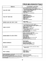
TROUBLESHOOTING
PROBLEM
CAUSE/REMEDY
(SEE INDEX)
Push Clutch/Brake
Pedal Into Brake Position
Move Attachment
Clutch Lever to "Disengaged
Position
Fill Fuel Tank with Gasoline. Check Fuel Line end Carburet
WILL
WILL
NOT START
NOT TURN
{clean If necessery/
Replace Fu_l Filter
Check fuse for fault and replace
Recharge or replace Battery
Check WiHng
Replace Spark Rug end adjust gap
Charge Battery
Replace Ignition Switch
Depress Clutch/Brake
Pedal
Disengage
Attachment
Clutch
Replace Interlock Switch
Replace Solenoid
Replace Fuse
Check All Wire Connections
OVER
Replace
ENGINE
HARD
ENGINE
ENGINE
CLICKS
BUT WON'T
START
Place Throttle Control In "FAST"
position
and run starter several times to clear our gas
Remove and clean Fuel Tank and lines Replace Fuel F/her
Remove Air Filter and clean
Replace Spark Plug and adjust gap
Replace Batte_
Check the wiring and Spark Plug
Drain Fuel Tank and Carburetor,
use fresh fuel and
replace Spark Plug
Make necessary adjustments
to Carburetor
Major Engine Overhaul
OR LACKS
Shift to a lower gear or reduce load
Remove and clean Fu_l Tank; replace Fuel Filter
Remove and clean Air Cleaner
Make necessary carburetor adjustments
Clean Air Screen
Add or change ell
Replace Spark Plug
Check Spark Plug and check for loose wires
Major Engine overhaul
Drain Fuel Tank and Carburetor and refill
POWER
Clean Air Screen
Add or change oil
Clean Engine Cooling Fine
Remove and clean Muffler or replace
Remove and clean Air Fi_er
OVERHEATS
Use
NO LIGHTS
WON'T
Starter
Charge or ReplaceBattery
TO START
MISSES
Lever
fresh fuel and adjust
Check Fuse, Switch
Headlight Bulbs
Carburetor
and wire connections,
Replace
Check Fuse and replace
Replace Battery
Replace
Regulator
Replace Alternator
CHARGE
OPERATOR
PRESENCE
SYSTEM
WILL NOT SHUT
DOWN
WHEN
OPERA TOR LEA VES SEA T,
Note: This tractor Is equipped
with an operator presence sans.
ing system Any attempt
by the operator to leave the seat with
the enigne running eric]the attchment
clutch engaged
will shut
down the engine,
Engage attachment
clutch
Check all wire connections
Check seat switch
Check operator
Check PTO Switch
25
l>resence
relay
TROUBLESHOOTING
Check air pressure in tires
Check trent to rear and side to side mower adjust.
mant
Use e slower
ground speed
Check engines RPM's Irefer to Carburetor
Adjustment)
Replace mower bladea
UNSATISFACTORY
MOWER PERFORMANCE
UNEVEN DISTRIBUTION
OF CLIPPINGS
Reinstall mower
blades with top of blade
Replace with proper mower
blades
Re-adjust mower
drive belt
MOWER
BLADES
EXCESSIVE
WILL NOT
MOWER
UNEVEN
Install new Mower Drive Belt
Reinstall Mower Drive Belt
Adjust Mower Drive Bolt
Replace Frozen Mandrel
Replace Frozen Idler Pulley
ROTATE
VIBRATION
WiND ROWING STRIPPING
OF GRASS CLIPPINGS
up
Replace Bent or Unbalanced Blades
Replace Mozldrel, Straighten Deck or replace
OR DROPPING
Let grass dry out
Clean undersideof Mower Deck
Readjust Mower
CUT OR SCALPING
Readjust Mower
26