1
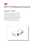
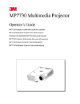
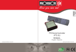
Quick Installation
Guide
For the PTZ Dome Controller
Remote control for PTZ and PT cameras
1
Thank You for Choosing a Q-See Product!
All of our products are backed by a conditional service warranty covering all hardware for 12 months
from the date of purchase. Additionally, our products also come with a free exchange policy that
covers all manufacturing defects for one month from the date of purchase. Permanent upgrading
service is provided for the software and is available at www.Q-See.com.
Be certain to make the most of your warranty by completing the registration form online. In addition to
warranty and technical support benefits, you’ll receive notifications of product updates along with free
downloadable firmware updates for your camera. Register today at www.Q-See.com!
Please see the back of this manual for exclusions.
Contents
INTRODUCTION
Before you begin
1. COMPONENTS & CONNECTIONS
1.1 Control Module
Connecting the Control Module
LED Readout
1.2 Remote Control
2. OPERATION
2.1 Setting Address and Protocol
Setting Baud Rate and Protocol
4
4
5
5
6
7
8
9
9
9
2.2 Directional Controls
10
2.3 Other Controls
10
Speed
Auto
10
10
2.4 Programming
11
Preset Points
Auto Pan
Scan
Surveillance Pattern
11
12
13
13
2.5 Special Functions
APPENDIX
Troubleshooting
13
14
14
WARRANTY
15
PRODUCT SUPPORT
15
Use your smartphone’s QR app to go directly
to Q-See’s product registration page.
© 2012 Q-See. Reproduction in whole or in part without written permission is prohibited. All rights
reserved. This manual and software and hardware described herein, in whole or in part, may not be
reproduced, translated, or reduced to any machine-readable form without prior written approval.
Trademarks: All brand names and products are trademarks or registered trademarks of their
respective owners.
Q-See is a registered trademark of DPS, Inc.
Disclaimer: The information in this document is subject to change without notice. The
manufacturer makes no representations or warranties, either express or implied, of any kind with
respect to completeness of its contents.
Manufacturer shall not be liable for any damages whatsoever from misuse of this product.
2
3
INTRODUCTION
This quick-start guide is written for the QD6531Z and QD6505P speed dome cameras with remote
control and was accurate at the time it was completed. However, because of our ongoing effort to
constantly improve our products, additional features and functions may have been added since that
time. We encourage you to visit our website at www.Q-See.com to check for the latest firmware
updates and product announcements.
This guide is intended to assist you in adding the remote control function to your camera. Complete
instructions on setting up your PTZ camera itself are included in the accompanying user manual for
your camera.
Throughout the manual we have highlighted warnings and other important information that will assist
you in operating your new system in a safe and trouble-free manner. Please take the time to read and
follow all instructions and pay attention to alerts as shown below:
COMPONENTS & CONNECTIONS
CHAPTER 1
The controller for your camera consists of two parts; the Remote Control, and the Control Module
which contains the infrared receiver as well as a digital readout. The control wires from your camera
connect to ports on the back of the module.
1.1 CONTROL MODULE
The Control Module receives the signals from the Remote Control and transmits control instructions to
the camera through the wires connected to the RS485 block at the back of the module. The Control
Module does not have any control over the video signal sent from the camera as that is delivered
directly to the DVR or monitor. All settings are actually stored in the camera itself, the Control Module
serves to communicate your instructions to your camera.
IMPORTANT! Red boxes with this icon indicate warnings. To prevent
possible injury or damage to the product, read all warnings before use.
1
2
NOTE! Text in blue boxes with the Information icon offer additional
guidance and explanations about how to make the most out of your system.
About PTZ
The term “PTZ” means Pan-Tilt-Zoom, and describes a camera that can rotate, elevate and zoom in
on a subject. Some cameras, such as the QD6505P, only feature the pan and tilt functions, making
them Pan-Tilt cameras. Throughout this manual we will refer to the PTZ operations. The basic
operations are identical regardless of whether your camera has the zoom feature.
3
4
BEFORE YOU BEGIN
You will need:
1. A surge protector
We STRONGLY recommend that you use one that has the following specifications:
• UL-1449 Rated
• Clamping voltage of 330 or lower
• Joule rating of at least 400
• Response time of 10 nanoseconds or less
2. A small, Phillips-head screw driver to secure the control wires from the camera into the RS485
module on the Control Module.
NOTE! If you have your DVR set to record when motion is detected, the movement
of the PTZ camera will trigger recording as well as any alerts that you have set up,
creating the potential for multiple false alarms. Depending upon your situation and
specific needs, you should disable alarms, e-mail alerts and other notifications relating to motion
detection for the specific channel that your PTZ camera is connected to. You may also wish to
change the recording schedule, speed and/or quality for this channel to save disk space, if needed.
4
PICTURE 1-1
# Name
Description
1
LED
ALPHA-NUMERIC
DISPLAY
This digital readout displays information regarding camera
address, preset point number, surveillance pattern number, etc.
2
IR RECEIVER
Receives commands from Remote. Located behind front
faceplate.
3
RS485 PORT
Control wires from PTZ camera are connected here.
4
POWER INPUT
12V power supply connects here.
5
CONNECTING THE CONTROL MODULE
It is recommended that you test your camera near your DVR before mounting it in order to ensure that
proper connections have been made and that everything is operating normally.
STEP 1. Connect the power/video/control extension cable to the camera according to the
instructions in the camera’s manual. These are located in the section entitled “Connecting
the Camera.”
LED READOUT
When the Control Module is powered up, it will display one of two messages - A001 or P001. The
former indicates that the camera’s control address is 1, while the latter shows that the camera is at
preset point number 1. These and other messages will be explained throughout the manual as they
appear in operational instructions, but they are collected below for your convenience.
STEP 2. Connect the power and the video leads on the opposite end of the extension cable to the
power adapter and DVR or standalone monitor, respectively.
STEP 3. The bare metal control leads on the extension cable will need to connect to the orange
RS485 block on the back of the Control Module.
This block can be unplugged from the Module if needed, but care must be taken while
connecting the cables that the side with the screw heads is up to maintain proper orientation
and to avoid connecting the wrong wire to the wrong port.
5
48
RS / +A
-B
Use a Phillips-head screw driver to turn
the screws counter-clockwise making
sure that the ports are open.
At least one wire will be labeled. The
white wire is the positive lead (also
referred to as RS485A or “Y”) and it
should be inserted into the left port. Use
the screwdriver to close the jaws of the
port until the wire is firmly attached.
Repeat this procedure with the negative
black (RS485B or “Z”) lead.
If you removed the orange RS485 block
during the connection, plug it back into
the Control Module at this time.
Message
Meaning
A001
A001
Camera address is “1”. This address can be set (1-255) using the
DIP switches inside the camera as described in the User Manual.
If the address is changed, you will need to change the address in
the Module using the Remote Control
AUTO
Auto
Rotates the camera 360° starting and ending at the home point
CLR-
CLR
Clear. This indicates that you have cleared a setting using the
Delete button on the remote.
D=24
D represents the Pelco-D communication protocol. 24 means
2400bps communication speed. This is the default setting for your
D=24
camera. Like the address, protocol and speed are both set using
DIP switches and the Module will need to be set as well.
Home
PICTURE 1-2
STEP 4. Plug the lead from the Control Module’s power adapter into the port on its back panel. It
is recommended that this power supply be plugged into a UL-1449 rated surge protector to
prevent damage in case of spikes of surges in power from the outlet.
IMPORTANT! We recommend connecting your camera and the Control
Module to a UL-1449 rated surge protector. It should have a joule rating of
at least 400, a response time of 10 nanoseconds or less and a clamping
voltage of no more than 330 volts.
6
PICTURE 1-3
Points camera to its preset home point.
Starting point for the auto pan function
Lt-A
Lt-B
P001
P001
Preset point 1. You can set up to 80 points.
P=12
P=12
The camera is set to use the Pelco-P communication protocol at
1200bps
Ending point for the auto pan function
Pattern Starts the camera moving through a surveillance pattern
Run
PstA
PSt0
S-63
SEtU018
PSTA
The starting point of a surveillance pattern
PST0
The ending point of a surveillance pattern
S-63
Camera movement speed is set to 63 (the fastest setting)
Set
U018
Saves a preset point
The controller is using software Update version 18.
7
1.2 REMOTE CONTROL
All of the commands and settings for your PTZ camera will be made using the remote that came with
your camera. If you are connecting your camera to a DVR, the remote that came with that system will
not work for controlling your camera.
#
Button
Function
1
Escape
Goes to address input mode
2
Display
Shows current settings
3
Preset
Press to create a preset point
4
Run
Run surveillance pattern
Home
Directs camera back to “home”
point
6
Setup
Press to change baud rate
7
Delete
Clear preset point
8
Pattern
Create surveillance pattern
9
B
10 A
Mark start and end points for
auto pan function
11 Numbers
Enter numbers
12 Clear
Clears number entry
5
13
Multi-digit
14 Shot
15
16
Press to go to preset point
Directional Moves the camera to desired
Controls
position
Speed
Press and then enter desired
speed (2-63)
Cam
Press to change camera
address
18 Enter
Confirm selection/action
17
19
Auto
20 Focus
8
Press before entering numbers
with two or more digits
Spins camera 360° from home
point
21 Iris
Camera automatically adjusts
focus and light level. These are
not usable with your camera.
22 Zoom
Zoom in or out
1
2
3
4
5
11
12
13
14
ESC
SETUP
DISP
PRESET PATTERN
RUN
HOME
DELETE
A
B
1
2
3
4
5
6
7
8
9
C
-/--
0
SHOT
CAM
15
ENTER
16
SPEED
20
FOCUS+
OPEN
6
7
8
9
10
21
23
18
SETTING BAUD RATE AND PROTOCOL
Press the DISP button to show the current baud settings. Please note that you may have to push
DISP multiple times to cycle through the various settings (speed, firmware version, etc.) to reach the
baud settings. If the Control Module is set to the factory default, it will read d=24 meaning that it is
set to use the Pelco-D protocol at 2400 bits per second (bps).
19
ZOOM+
22
25
S2
S3
S4
F1
F2
F3
F4
P1
P2
P3
P4
P5
P6
P7
P8
Your camera is set by default to an address of 1, with a baud rate of 2400 using the Pelco-D protocol.
You should not need to change this except in unique circumstances, such as multiple cameras
connected to a single Control Module.
For the Control Module, these settings need to be changed to match those in the camera using the
remote.
AUTO
S1
2.1 SETTING ADDRESS AND PROTOCOL
It is possible to connect multiple PTZ cameras to the Control Module using the RS485 block on the
back. However, each camera will need to have a distinct address - from 1 to 16 - in order to ensure
that commands are being issued to the correct camera. In addition, both camera and Control Module
must use the same communication protocol in order to interact. Both the camera and the Control
Module can use the Pelco-D or Pelco-P protocols. The speed of this communication, called the baud
rate, is also important as a lower communication speed allows control of the camera over longer
distances. It should be noted, however, that in most applications a higher speed isn’t a major factor.
Each attached camera can use a different protocol and baud rate, if desired.
17
To change baud rate and protocol
ZOOM-
CLOSE
CHAPTER 2
If you need to change the default settings, you must do so both in the camera and on the Control
Module. In the camera, they are made using DIP switches as covered in the Setting Baud Rate
and Address section of the User Manual that came with your camera.
IRIS
FOCUS-
OPERATION
STEP 1. Press and hold the Setup button
for 3 seconds until you see the current
baud rate settings, such as d=24
24
STEP 2. Press the up or down arrow key to
switch between Pelco-D (d) and Pelco-P
(P) protocols.
PICTURE 2-1
23
Speed
Shortcuts
Increase or decrease speed.
S1=8, S2=40, S3=51, S4=63
STEP 3. Use the left and right arrow keys to change the baud rate between 12/24/48/96.
24
Focus
Shortcuts
Not usable with this camera
STEP 4. Press Enter to save your setting.
25
Preset
Shortcuts
Moves camera directly to preset
points 1-8
PICTURE 1-4
Pressing and holding C while in the baud rate mode will blank the LED readout for 10 seconds and
reset the Control Module back to Pelco-D at 2400bps.
9
To change address
STEP 1. Press the CAM button until it shows the address number, A=001
STEP 2. If the desired channel is 1-9, simply push that number on the remote. For addresses
10-16, you will need to press the “-/--” button before entering the two digits. You may press
the C button to delete a digit.
ESC
SETUP
STEP 3. If you are entering a two-digit address, you will need toDISPpressPRESET
EnterPATTERN
after the
second
DELETE
digit.
RUN
HOME
A
B
When the LED dispaly is showing address information, clicking and holding Delete for three seconds
will clear all addresses.
1
2
3
2.2 DIRECTIONAL CONTROLS
The most basic method for controlling the PTZ camera is by using the4 directional
5 controls
6 on the
remote. The four, blue directional control buttons at the center of the remote allow you to move the
camera both left and right as well as up and down. For horizontal movement, the camera can rotate in
7
8
9
a full circle. Vertically, the camera only move between straight down and level.
For cameras with the zoom function, the two buttons marked Zoom+ and Zoom- allow you to magC
-/-0
nify the target area by three times.
It should be noted that the other buttons in that
area - the ones controlling Focus and Iris - do
not function with these cameras. This is due to
the fact that both cameras automatically focus
on a subject and the automatic iris adjusts the
level of light reaching the sensor without the
need for manual input.
SHOT
Setting a point
STEP 1. Using the directional buttons, point your camera to the desired location. Adjust the zoom
if needed/available.
STEP 2. Press and hold the Preset button for approximately 3 seconds until the Set- message
appears.
STEP 3. Enter the number for this preset.
If the number is higher than nine, you will need to press press the “-/--” button before
entering the two digits (up to 80) and then press Enter.
Home point
This is essentially Preset Point #0. This is the point that the camera will return to when you press the
Home button. It differs from the other preset points by being the starting and ending point for a 360degree rotation of the camera when the the Scan button is pressed. The camera will retain any zoom
settings set for the home point during its rotation.
ENTER
AUTO
FOCUS+
OPEN
FOCUS-
CLOSE
ZOOM+
IRIS
S1
PRESET POINTS
The user is able to create up to 80 preset points which are stored in the memory of the Control
Module. The first eight of these can be accessed with the touch of a single button at the bottom of
the remote which will cause the camera to point at the desired location. The remaining preset points
require the use of more than one button to access.
CAM
SPEED
Using the directional controls will override any
current automatically running operation of the
camera.
2.4 PROGRAMMING
The camera can be programmed to store preset points in which you save a specific position including zoom, if applicable - for access later. In addition, you may also record a surveillance pattern
with up to 16 stops that the camera will cycle through. It is this pattern which is most commonly used
to automatically scan a wide area.
S2
ZOOMS3
PICTURE 2-2
S4
F1
F2
F3
F4
2.3 OTHER CONTROLS
SPEED
P4
The camera’s movement speed can be adjusted from slowest (2) to P1fastestP2(63) byP3two methods:
1. Shortcut buttons - These buttons are located at the bottom of the remote. S1=8, S2=40, S3=51,
P5
P6
P7
P8
S4=63
2. Pressing the Speed button and then entering the desired speed before pressing Enter.
Setting the Home point is identical to the procedure used to set any other preset point above, except
that once the Set- message appears, you should press the Home button rather than a number. The
Control Module’s LED readout will display HONE, to indicate that it has been set.
Clearing a preset point
You may overwrite a preset point by positioning the camera to a different location and then assigning
it the same number as the point you want to delete. Or, you may go to the preset point and then press
and hold the DELETE button for about three seconds until the message CLR- appears on the Control
Module.
You may clear ALL of the preset points by following the instructions for setting a preset point and
entering 95. This cannot be undone.
AUTO
This will cause the camera to move to its Home Point (see next section) and begin rotating 360° until
interrupted by another command from the Remote, such as pressing a directional button.
10
11
IRIS
Going to a preset point
Once you’ve set your preset points, you can use
the remote to direct the camera to those spots.
For preset points 1 through 8, you will only need
to push the appropriate Shortcut button labeled
P1 through P8 at the bottom of the remote.
To point your camera at preset points 9 through
80, you will need to follow these steps:
FOCUS-
ZOOM-
CLOSE
S1
S2
S3
S4
F1
F2
F3
F4
P1
P2
P3
P4
P5
P6
P7
P8
STEP 1. Press the Shot button.
STEP 2. Press press the “-/--” button.
PICTURE 2-3
SCAN
The scan pattern is simply a 360-degree horizontal rotation of the camera based on the position and zoom settings - of the Home point (see above.)
SURVEILLANCE PATTERN
You can create a surveillance pattern that will be recorded by the camera for it to follow. It does not
use any of the preset points you may have created, but rather copies the exact motions of the intial
pattern. This includes pauses at selected points. If, for example, your intial pattern includes a pause
for 10 seconds at a particular spot, the pattern will include a 10-second delay at that point. You may
have up to 16 points along the pattern. You do not have to end the pattern at the same position from
which you began as the camera will return to the starting point to repeat the pattern.
Setting a pattern
STEP 1. Press and hold the Pattern button until the LED display reads PstA
STEP 2. Create your surveillance pattern by directing your camera as desired.
STEP 3. Enter the two-digit preset point number.
STEP 3. When you have finished your pattern, press and hold the Pattern button again until the
LED display reads PstO
STEP 4. Press Enter.
The camera can be directed to the Home point by using the Home button located at the top of the
remote.
AUTO PAN
You can set up your camera to constantly move back and forth between two points. This action,
called an auto pan, can be useful in surveying a wider area than can be seen by a single camera, for
example. The two points can have different focus settings (if applicable).
STEP 1. Position the camera at the desired
starting point.
A
STEP 4. Repeat for the end point, using the
B button this time.
Press the Run button to have your camera begin the surveillance pattern. The LED display will read
the PrUn message to indicate that it is running your pattern. You may override and interrupt the
pattern at any time by pressing a directional control, zoom or Preset shortcut button.
2.5 SPECIAL FUNCTIONS
There are several additional functions which are saved as presets and which can be accessed in the
same manner:
STEP 2. Press and hold the Preset button
for approximately 3 seconds until the
Set- message appears.
STEP 3. Press the A button at the top of the
remote. The message Lt-A will appear.
STEP 4. Press Enter to save your pattern.
B
Press Shot
Press -/-Enter function number
Press Enter
Preset Operation
93
97
Camera pans 360° before reversing and
panning 360° again
94
Clears all settings except presets
95
Clears all settings including presets
After you press Enter, the function will take place.
PICTURE 2-4
STEP 5. Press A to begin the pan.
Pressing B will cause the camera to pan in the opposite direction, skipping the area covered by the
other pan. Pressing any directional key will stop a pan cycle. Points A and B and be reset as needed.
12
13
APPENDIX
TROUBLESHOOTING
Symptom Cannot control camera.
Solution
Check that the RS485 wires are securely connected and in the
proper ports.
Check that settings for protocol, baude rate and address match
those set within the camera.
Focus, Iris and Zoom functions do not work.
Iris and focus functions are handled automatically by the camera.
The QD6505P camera does not have a zoom lens.
Buttons F1 through F4 are non-functional.
These buttons are focus shortcuts and are not supported by your
camera.
Remote buttons not working.
14
Ensure that batteries are properly aligned in remote.
Replace AAA batteries in remote.
Make sure that Control Module front panel is not blocked.
WARRANTY
Q-See is proud to back all of our products with a conditional service warranty covering all hardware
for 12 months from the date of purchase. Additionally, our products also come with a free exchange
policy that covers all manufacturing defects for one month from the date of purchase. Permanent
upgrading service is provided for the software.
Liability Exclusions:
Any product malfunction or abnormalities in operation or damage caused by the following reasons are
not within the free service scope of our company:
1. Equipment damage caused by improper operation.
2. Improper equipment operation environment and conditions (e.g., improper power, extreme
environmental temperatures, humidity, lightning and sudden surges of electricity).
3. Damage caused by acts of nature (e.g., earthquake, fire, etc).
4. Equipment damage caused by the maintenance of personnel not authorized by Q-See.
5. Product sold over 12 months ago.
In order to fulfill the terms of your warranty, you must complete the registration process after
purchasing our product. To do this, simply fill out the User’s Information Card on our website at
http://q-see.com/support/registration-form.php
PRODUCT SUPPORT
SUPPORT, DOWNLOADS,FIRMWARE UPDATES & MANUALS
24/7 Technical Resources
Live Chat (M-F, 9-5 PST)
www.Q-See.com/Support
15
Digital Peripheral Solutions, Inc.
8015 E. Crystal Drive
Anaheim, CA 92807
16