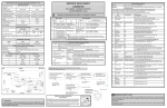
1
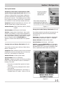
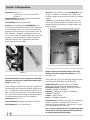
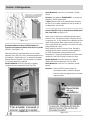
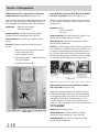
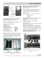
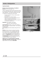
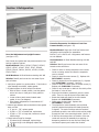
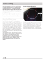
All About
Servicing
2012 Service Updates
™
©2012 Electrolux Home Products Inc.
10200 David Taylor Drive
Charlotte, NC 28262
Publication #5995612875
May 2012
Section 1 Refrigeration
Safe Servicing Practices
Avoid personal injury and/or property damage by observing important Safe Servicing Practices.
Following are some limited examples of safe practices:
1.
DO NOT attempt a product repair if you have any doubts as to your ability to complete the repair in a safe and satisfactory manner.
2.
Always Use The Correct Replacement Parts as indicated in the parts documentation. Substitutions may defeat compliance with Safety Standards Set For Home Appliances.
3.
Before servicing or moving an appliance:
• Remove power cord from the electrical outlet, trip circuit breaker to the OFF position, or remove fuse.
4. Never interfere with the proper operation of any safety device.
5.
Use ONLY REPLACEMENT PARTS CATALOGED FOR THIS APPLIANCE. Substitutions may defeat compliance with Safety Standards Set For Home Appliances.
6. GROUNDING: The standard color coding for safety ground wires is GREEN, or GREEN with YELLOW STRIPES. Ground leads are not to be used as current carrying conductors. It is EXTREMELY important that the service technician reestablish all safety grounds prior to completion of service. Failure to do so will create a hazard.
7. Prior to returning the product to service, ensure that:
• All electrical connections are correct and secure.
• All electrical leads are properly dressed and secured away from sharp edges, high-temperature components, and moving parts.
• All non-insulated electrical terminals, connectors, heaters, etc. are adequately spaced away from all metal parts and panels.
• All safety grounds (both internal and external) are correctly and securely connected.
• All panels are properly and securely reassembled.
© 2012 Electrolux Home Products, Inc.
WARNING
This service manual is intended for use by persons having electrical and mechanical training and a
level of knowledge of these subjects generally considered acceptable in the appliance repair trade.
Electrolux home products cannot be responsible, nor assume any liability, for injury or damage of
any kind arising from the use of this manual.
1-1
of 1Contents
Table
Section
Refrigeration
Safe Servicing Practices................................... 1-1
Table of Contents............................................. 1-2
Section 1 - Refrigeration................................. 1-3
Side-by-Side Models.........................................1-3
Excessively Cold Freezer Temperatures on
Side-by-Side Counter Depth Models with VCC........1-3
Strong Odor Inside Side-by-Side Models................1-3
Flashing Code “4” on Side-by-Side Models.............1-4
French Door Models.........................................1-4
No Ice in Freezer; Freezer Drawer Freezing Shut on
French Door Non-Dispenser Models.......................1-4
Frozen Freezer IM Fill Tube on French Door
Non-Dispenser/Dual-Ready Models........................1-5
Recommendation for Use of Stationary Door Rack
on French Door Models with Bullet-Style FFIM........1-5
Recommendation for Use of Gasket to
Seal FFIM Housing on French Door Models
with Bullet-Style FFIM...........................................1-6
Model Transition from Bullet-Style to Flex Tray
FFIM on French Door Dispenser Models.................1-6
Warm Fresh Food Condition on French Door
Models................................................................1-7
Flipper Mullion Improvement.................................1-7
Recommendation for Use of FFIM Gaskets on French
Door Dispenser Models with Flex Tray FFIM...........1-8
Frozen FFIM Fill Tube on French Door Models
with Flex Tray FFIM..............................................1-8
Folded FFIM Fill Tube Flange on French Door
Models with Flex Tray FFIM...................................1-9
Ice Clumping in Ice Bin on French Door
Models with Flex Tray FFIM...................................1-9
FFIM Defrost Failure on French Door Dispenser
Models with Flex Tray FFIM...................................1-10
Noisy FFIM Fan on French Door Dispenser
Models with Flex Tray FFIM...................................1-10
Auger Motor Freeze-Up on French Door
Models Flex Tray FFIM..........................................1-10
Improved Ice Dispensing with Ice Breaker Blade
on French Door Units with Flex Tray FFIM..............1-11
Improved Position of Flex Tray Ice
Maker Fill Tube....................................................1-11
Elimination of Magnets from Stabilizer Bar on
Frigidaire French Door Models...............................1-11
“SY CE” Error on French Door Models with Flex
Tray Ice Maker.....................................................1-12
Side-By-Side and French Door Models............1-12
Water Dispenser Dripping on Side-by-Side and
French Door Models.............................................1-12
Improved Water Filters for Side-by-Side and
French Door Models.............................................1-13
1-2
New User Interface Kits for ICON and Electrolux
Side-by-Side and French Door Models....................1-13
Top Mount Models............................................1-14
Excessive Frost in the Freezer on Top Mount
Models................................................................1-14
Improved Top Mount Cabinet and
Gasket Design......................................................1-15
All Freezer/Refrigerator Models......................1-15
Crisper/Deli Drawer Difficult and/or Noisy
to Open or Close on Tall Twin Models....................1-15
Door Seal Adjustment on Upright Freezers.............1-16
Excessive Evaporator Fan Noise on Frost
Free Models.........................................................1-16
Section 2 - Dishwashers...................................2-1
Door Gaskets.......................................................2-1
Pumps.................................................................2-1
Controls...............................................................2-1
Dispensers...........................................................2-1
Heaters...............................................................2-1
Turbitity Sensor...................................................2-1
Drain Valve..........................................................2-1
Odor...................................................................2-1
Tips on checking the detergent dispenser..............2-2
Long Run times on E- Star model
dishwashers.........................................................2-2
Flashing Codes.....................................................2-3
Detergent Usage Guide........................................2-4
Section 3 - Cooking.......................................... 3-1
Push Button Microwave Door Does
Not Open Easily...................................................3-1
Melting Knobs on Gas Range................................3-1
Faint gas smell when using the “Twin Burner”
simmer position...................................................3-1
316354300 Knob Heat Shield Installation
Instructions.........................................................3-2
F68 / F69 Fault codes on Electronic Oven
Controls – Electric Freestanding Ranges................3-3
EOC Will Not Program on New Range- Gas
and Electric Ranges..............................................3-3
Auto Rack Sticking After Self Clean – Gas and
Electric Ranges....................................................3-3
Cooktop Lockdown Conversion..............................3-3
Cooktop Lockdown Conversion Instructions...........3-4
Glass or Ceramic Cooktop Damage .......................3-4
Broken Cooktop Examples....................................3-6
Damage Due to Defect.........................................3-8
Instructions for installing resistor on glass
cooktop units with serial numbers starting
with 3F...............................................................3-9
Section 1 Refrigeration
Side-By-Side Models
Excessively Cold Freezer Temperatures on Sideby-Side Counter Depth Models with VCC (RF1101)
Freezers on Side-by-Side Counter-Depth refrigerators
operate at excessively low temperatures even though
the set point is at zero. This condition can also contribute to freezing of the drain (see RF1103) or excessively
cold conditions in meat and crisper drawers (RF1004).
Symptoms: Reported temperatures are as low as -14F.
May also freeze items in crispers and deli pan.
Models Affected: EI23CS, EW23CS, FGHC23, FPHC23, LGHC23
Figure 1-1
Serial Numbers: 4A740xxxxx to 4A131xxxxx
Strong Odor Inside Side-by-Side Models (RF1106)
Solution: Replace Main Control Board. Main control
software was updated to correct freezer temperatures.
Also, see Freezing or Excessively Cold Condition in Meat
and Crisper Drawers (RF1004). When meat or crisper
pans are freezing, install kit 5303918489 and
determine if Main Control Board needs to be replaced
also.
Foam blocks located on the sides of the evaporator coil
may be deformed by heat from the defrost heater.
(see figure 1-2)
Symptoms: Consumers may detect an objectionable
odor sometimes described as “plastic” or “chemical”.
Models Affected: All Side-by-Side models
Serial Numbers: 4A010xxxxx – 4A122xxxxx
Freezing Drain on Side-by-Side Models (RF1103)
Frozen drain prevents proper draining of water during
defrost. (see figure 1-1)
Solution: Install kit 5303918593 for 23’ StandardDepth or 5303918594 for 23’ Counter-Depth and 26’
Standard Depth units. Kits contain replacement foam
blocks, replacement defrost heater and air filters.
Symptoms: Water breaches the drain area, the freezer
compartment, and may potentially leak out of the front
of the unit. Ice formation on freezer floor.
Models Affected: All Side-by-Side models
Serial Numbers: Prior to 4A109xxxxx
Solution: Diagnose and repair the following conditions
known to have the potential to cause or contribute to
freezing of the drain:
• Drain tube not seated flush against the freezer
liner floor.
• Drain trough opening misaligned with the drain
tube opening.
• Excessively cold temperatures in the freezer on
Standard-Depth VCC models. (Refer to RF1101)
Figure 1-2
1-3
Section 1 Refrigeration
Flashing Code “4” on Side-by-Side Models (RF1203)
French Door Models
Side-by-Side refrigerators equipped with Beta Control
experience damper failure demonstrated by flashing code
4 in fresh food temperature display. On models equipped
with single-digit temperature display, the compressor
fails to start up following flashing code 4. (see figure 1-3)
No Ice in Freezer; Freezer Drawer Freezing Shut
on French Door Non-Dispenser Models (RF1102)
(see figure 1-4)
Symptoms: Flashing “4” error code, loss of cooling (on
single-digit display control models only), poor cooling
performance (varied depending on position of damper at
the time of failure).
Models Affected: Side-by-Side models with
temperature controls located inside FF compartment.
Serial Numbers: Prior to 4A137xxxxx
Solution:
For single-digit display models:
• If cooling is lost, it can be restored immediately
by cycling power to the unit. This is a temporary
resolution intended to restore cooling until
diagnosis and repair can be completed.
• Loss of cooling following flashing 4 error indicates
that the unit needs a replacement control board
with software revision 1.2 (Single-Digit models
only).
For all affected models, follow procedures outlined in the
service flash to properly diagnose and repair the cause
of flashing code 4 error. Procedures focus on identifying
poor electrical connections and on preventing moisture
migration into the unit and into the damper housing.
Figure 1-3
1-4
Non-Dispenser French Door units exhibit issues with
management of water flow to the freezer ice maker. Water continues to drip into the fill cup after water
dispensing stops. This condition can lead to ice build-up
in the fill cup. As a result, freezer ice maker may stop
producing ice. In addition, once ice builds-up all the way
to the fill tube, additional dispensed water may spray
onto drawer slides and freeze the drawer shut.
Symptoms: No ice in FZ
FZ drawer frozen shut
Models Affected: Electrolux & ICON - EI28BS36 &
51, EI23BC36 & 51, E23BC68, EI27BS16
Frigidaire - FGHN
Serial Numbers: Electrolux & ICON: 4A931xxxxx to
4A106xxxxx
Frigidaire: 4A022xxxxx to 4A106xxxxx
Solution: For Electrolux & ICON models, install
kit 5304482109. For Frigidaire models, install kit
5304482110. Both kits retrofit the unit with triple water
valve, which prevents water drip-on into the fill cup.
Figure 1-4
Section 1 Refrigeration
Frozen Freezer IM Fill Tube on French Door
Non-Dispenser/Dual-Ready Models
(see figure 1-5)
Recommendation for Use of Stationary Door Rack
on French Door Models with Bullet-Style FFIM
(RF1001) (see figure 1-6)
Water in the freezer ice maker tube may freeze. This
may be caused or intensified by several conditions,
including low fresh food temperature setting, air leak
around the air duct, or geometry of the fill tube. Note
that this condition is not related to that addressed in
RF1102.
Units built with tilt-out door rack must be retrofitted with
stationary door rack. Tilt-out door rack has the potential
to keep the door from closing completely when the rack
is overloaded. This results in poor temperature
performance and excessive frosting. In addition, on units
equipped with Fresh Food Ice Maker an open freezer
door will initiate freezer recovery mode and will stop ice
production.
Symptoms: No ice in FZ
Models Affected: Electrolux & ICON - E23BC68,
EI23BC36 & 51, EI27BS16 & 26, EI27BS26, EI28BS36 &
51
Frigidaire - FGHB2846, 69 & 78, FGHG2344, FGHN2844
Crosley - CFD28
Lowe’s - LGHB2869, LGHN2844, LGUB2642
Serial Numbers: Prior to 4A210xxxxx
Solution: Replace freezer ice maker fill tube with kit
5303918600. This kit contains an improved fill tube. When the new fill tube is installed, the connecting water
line must be shortened by 2-2.5” to prevent kinking. Foam pad needs to be placed on the tube only if it was
present on the original tube in the unit.
Also, investigate sealing of the air duct to the liner. Air
leak in this area can contribute to freezing of the fill tube. Use kit 5303918479 if needed to improve seal.
Symptoms: No ice in FF ice maker,
FZ drawer does not close completely.
Models Affected: 23 cu.ft. and 28 cu.ft. Electrolux &
ICON models with Bullet-Style FFIM. Not applicable on
27 cu. ft. models.
Serial Numbers: Prior to 4A110xxxxx
Solution: Replace door rack with 241824008 for
Electrolux and 241824009 for ICON models.
Figure 1-6
Recommendation for Use of Dielectric Grease
on French Door Models with Bullet-Style FFIM
(RF1207) (see figure 1-7)
Figure 1-5
Water intrusion into electrical connections within the
FFIM causes intermittent interruption of ice production
and melting of ice in the bin.
1-5
Section 1 Refrigeration
Symptoms: No ice in FF
Ice melting in the ice bin while FFIM is turned on
Models Affected: All ICON, Electrolux and Frigidaire
models with Bullet-Style FFIM
Serial Numbers: Prior to 4A113xxxxx
Solution: Use dielectric grease 5304485963 to improve electrical connections inside the FFIM. Application
is recommended on EEV, TH3, TH1 and fan connectors,
however it can also be used on any connector within the
FFIM assembly. In general, if all diagnostics pass and
the unit has 8.1/8.5 FFIM board yet the unit is either not
producing or not maintaining ice, water intrusion into
electrical connection can be suspected and dielectric
grease may resolve the problem.
Solution: Use two pieces of gasket 241869708 to seal
the gap. In addition, if excessive frost is found on the
ice mold, inspect the ice chute door to ensure it is sealing
properly.
* Note: Do not use weather stripping. Due to the variety of such products available, we cannot ensure that
acceptance criteria for materials in indirect contact with
food will be met.
Figure 1-8
Figure 1-7
Recommendation for Use of Gasket to Seal FFIM
Housing on French Door Models with Bullet-Style
FFIM (see figure 1-8)
Due to variation in flatness of the liner, the original FFIM
housing gasket may not provide sufficient sealing at the
top. This allows the relatively warm and moist FF air to
enter into the FFIM compartment. Moisture then can collect on the FFIM mold and impede or stop ice production
or cause excessive clumping of ice in the bucket.
Symptoms: No ice in FF
Models Affected: All models with Bullet-Style FFIM
Serial Numbers: Prior to 4A113xxxxx
1-6
Model Transition from Bullet-Style to Flex Tray
FFIM on French Door Dispenser Models (NF1102)
(see figure 1-9)
In the span of Q1, 2011 all French Door dispensing units
transitioned from Bullet-Style to Flex Tray FFIM.
Models Affected: All ICON, Electrolux, Frigidaire,
Crosley and Lowe’s models with Bullet-Style FFIM
Electrolux & ICON - E23BC78, EI23BC56, EI27BS26,
EI28BS56, EW23BC71, EW28BS71
Frigidaire - FGHB2844, 46, 69 & 78, FGUB2642,
FPHB2899, FPHF2399
Crosley - CFD26, CFD28
Lowe’s - LGHB2869, LGUB2642
Serial Numbers: Transition took place from 4A106xxxxx
through 4A114xxxxx. Units built prior to wk.6 are
equipped with Bullet-Style FFIM. Units built wk. 14 and
on are equipped with Flex-Tray FFIM.
It is of utmost importance to use engineering digit
number when ordering replacement components,
as model numbers did not change.
Section 1 Refrigeration
Key characteristics to determine FFIM type:
Figure 1-9
Warm Fresh Food Condition on French Door
Models (see figure 1-10)
Symptoms: Fresh Food temperatures 7-10F above set point.
Freezing in crisper drawers
Freezing water tank
Freezing FZ ice maker fill tube
Models Affected: Main board replacement
applicable only to Bullet-Style models - CFD26,
FGHB2869, FGHB2878, FGUB2642, FPHB2899,
LGHB2869, LGUB2642
Other solutions applicable to all French Door models.
Serial Numbers: Main board replacement applicable for
serial numbers prior to Flex Tray transition
(4A106 – 4A114). All serial numbers for other solutions.
Solution: Determine and address root cause.
•
Air duct leak around the bottom can cause warm FF
in the middle and towards the top of the cabinet.
This will always be combined with excessively cold
temperatures at the bottom of the FF which may
result in frozen veggies, water tank, and fill tube. Install kit 5303918479 to seal air leak.
•
Air leak between the back of the air duct and liner
can satisfy the FF thermistor prematurely before the
cabinet reaches set point temperature. If seal
between the air duct and the liner is not tight,
bypass is possible. Seal air leak. If air duct does not
have mounting tabs, replace. If the outer part of
the air duct is prevented from sealing to the liner by
the other components of the assembly, correct the
assembly.
•
Replace main board for affected models.
Substitutions are in place. Order per parts list.
Figure 1-10
Flipper Mullion Improvement (see figure 1-11)
Flipper mullion is constructed of metal face inserted into
a plastic housing. Due to dissimilar rates of thermal
expansion, flipper mullion bows in operating conditions.
Since the plastic housing contracts more than the metal
face, ends of the mullion bow towards the cabinet. This
creates gaps between the mullion and door gaskets at
the top and bottom of the mullion (similar to bi-metal
effect).
Symptoms: Moisture on the flipper mullion or gaskets. Poor cooling in FF
Models Affected: All French Door Models
Serial Numbers: Prior to 4A120xxxxx
Solution: Replace flipper mullion. New mullion has
flexible inserts at the top and bottom at the metal to
plastic interface. This allows the mullion to contract
without bending of the metal face when under operating
temperatures.
1-7
Section 1 Refrigeration
Serial Numbers: From Flex Tray transition (4A106 –
4A114)
Solution: Use gasket kit 5303918578. It contains all
gaskets in need of replacement.
* Note: Gaskets need not be replaced when servicing
the Flex Tray ice maker apparatus as the air handler is
not disturbed in the process.
Frozen FFIM Fill Tube on French Door Models with
Flex Tray FFIM (see figure 1-13)
Figure 1-11
Recommendation for Use of FFIM Gaskets on
French Door Dispenser Models with Flex Tray FFIM
(RF1206 ) (see figure 1-12)
Whenever service is performed within the air handler
assembly of the Flex Tray FFIM, all affected gaskets must
be inspected. If deformed, torn, or otherwise damaged,
gaskets must be replaced. If the air handler is loosened
or removed, gasket kit is required.
Models Affected: All ICON, Electrolux, Frigidaire,
Crosley and Lowe’s models with Flex Tray FFIM
When small ice cube size is selected and water supply
pressure is low, the quantity of water filling the ice tray
is extremely low. In this condition the individual ice cube
molds will be partially filled, causing small ice cubes, or
may not get filled at all, resulting in only a few ice cubes
being produced at a time.
When quantity of water in the tray is low, the heat is
removed quickly and the remaining cooling capacity in
the FFIM compartment causes excessively low
temperatures. These low temperatures can cause water
remaining in the FFIM fill tube to freeze over time.
Models Affected: All ICON, Electrolux, Frigidaire,
Crosley and Lowe’s models with Flex Tray FFIM
Serial Numbers: From Flex Tray transition (4A106 –
4A114)
Solution: ▪ Remove FFIM fill tube and clear ice
accumulated inside; reinstall the fill tube.
▪ Select ice cube size appropriate for the water supply pressure.
1-8
Figure 1-12
Figure 1-13
Section 1 Refrigeration
Folded FFIM Fill Tube Flange on French Door
Models with Flex Tray FFIM (see Figure 1-14)
Ice Clumping in Ice Bin on French Door Models
with Flex Tray FFIM (see figure 1-15)
When FFIM fill tube flange is folded over, it blocks water
from entering the ice tray and causes it to cascade over
the FFIM housing and onto the shelf below.
Large ice clumps with smooth bottom or section which
resembles curvature of the ice bin are indicative of water
entering the ice bin. This typically occurs due to
overfilling of the ice tray or splashing during fill.
Symptoms:
FFIM not making ice from installation or from FFIM service
Water on top shelf under FFIM
Sheet of ice on the liner wall next to FFIM
Sheet of ice on top of the FFIM housing
Models Affected: All ICON, Electrolux, Frigidaire,
Crosley and Lowe’s models with Flex Tray FFIM
Symptoms: Makes ice but cannot dispense
Models Affected: All ICON, Electrolux, Frigidaire, Crosley and Lowe’s models with Flex Tray FFIM
Serial Numbers: From Flex Tray transition (4A106 –
4A114)
Serial Numbers: From Flex Tray transition (4A106 –
4A114)
Solution: ▪ Lower fill time to prevent overfilling of ice tray during fill
Solution: Fill tube is folded when the FFIM housing is
not installed correctly. FFIM housing should be slid to
the back first and then raised into position to prevent
interference with the gasket and funnel assembly on
FFIM housing.
▪ Inspect water entry path for cause of
splashing; typically this will be the fill tube assembly or funnel. Reinstall or replace funnel or fill tube assembly.
▪ Correct fill tube misassembly; replace fill tube if
necessary.
▪ After reassembly, run several manual fills (FFIM service mode test 55C) to ensure water is entering ice tray.
▪ Check for splashing and correct if needed; adjust fill tube and funnel.
▪ Run several manual fills (FFIM service mode test 55C) to ensure water is not entering the ice bin.
* Note: Ice clump with irregular shape is typically
caused by sublimation of ice in low-usage situations.
This is a normal condition. Discard clumped ice and
replenish ice bin.
* Note: In service mode, the FFIM may be disconnected
and removed from the unit when running manual fills.
Figure 1-15
Figure 1-14
1-9
Section 1 Refrigeration
FFIM Defrost Failure on French Door Dispenser
Models with Flex Tray FFIM (see figure 1-16)
Noisy FFIM Fan on French Door Dispenser Models
with Flex Tray FFIM (RF1205) (see figure 1-17)
Most commonly, due to poor electrical connection or pin
back out. May also be due to shorted defrost heater or
wires damaged during brazing of the FFIM evaporator.
FFIM fan makes intermittent, buzzing noise. Over time,
the fan may stop completely and the ice maker will stop
producing ice.
Symptoms: Made ice, then stopped
Slow ice production
Models Affected: All ICON, Electrolux, Frigidaire,
Crosley and Lowe’s models with Flex Tray FFIM
Symptoms: No ice
Slow ice production
Fan noise
Models Affected: All ICON, Electrolux, Frigidaire, Crosley and Lowe’s models with Flex Tray FFIM
Serial Numbers: From Flex Tray transition (4A106 –
4A114)
Serial Numbers: From Flex Tray transition (4A106 –
4A114) through 4A206xxxxx
Solution: Diagnose reason for defrost failure and
correct.
▪ Check for pin back-outs at connections shown and at main board
▪ Inspect condition of wires
▪ Check defrost heater; should read approx. 197 Ohm resistance
Solution: DO NOT replace the fan, unless you determine
it to be defective. Resolution focuses on prevention of
ice build-up and directing defrost water away from the
fan. Remove mastic pad, ensure all refrigerant lines are
pushed back towards the liner and that neither the tubes
nor wires are pinched against the evaporator cover.
▪ Check defrost thermostat
Figure 1-17
Auger Motor Freeze-Up on French Door Models
Flex Tray FFIM (see figure 1-18)
Auger motor operates inside the air handler housing in
a humid and freezing environment. Moisture collecting
on the exposed portion of the rotor can cause the rotor
to freeze up. Rotor can be freed by approx. 30 sec.
of paddle activation, however this is a nuisance to the
consumer. Improved design covers rotor completely and
prevents ice build-up.
Order 241816602.
Figure 1-16
Symptoms: Not dispensing ice
Models Affected: All ICON, Electrolux, Frigidaire,
Crosley and Lowe’s models with Flex Tray FFIM
Serial Numbers: From Flex Tray transition (4A106 –
4A114) through 4A139xxxxx
1-10
Section 1 Refrigeration
Figure 1-19
Improved Position of Flex Tray Ice Maker Fill Tube
(see Figure 1-20)
Figure 1-18
Improved Ice Dispensing with Ice Breaker Blade
on French Door Units with Flex Tray FFIM
(see Figure 1-19)
Pyramid-shaped ice produced by the Flex Tray Ice Maker
tends to clump more than Bullet-Style ice. Ice breaker
blade was introduced to help break-up clumped ice prior
to dispense.
Fill tube position is essential to proper filling of the ice
maker tray. Ridge and notch were added to provide a
guide to proper installation of the replacement FFIM fill
tube. To service units built prior to implementation of this
design, the servicer must remove the ridge to allow the
part to fit into the old conduit. PN 241920103.
Models Affected: All Flex Tray FFIM FDBM models.
Serial Numbers: New part implemented 4A137xxxxxx
Symptoms: Cannot dispense ice
Slow ice dispense
Clumped ice
Models Affected: All ICON, Electrolux, Frigidaire,
Crosley and Lowe’s models with Flex Tray FFIM
Serial Numbers: From Flex Tray transition (4A106 –
4A114) through 4A141xxxxx
Replace the ice bucket with the latest design. To obtain
the latest bucket, order per parts list. Substitutions are
in place.
Figure 1-20
Elimination of Magnets from Stabilizer Bar on
Frigidaire French Door Models. (see Figure 1-21)
Magnets were removed from the upper basket stabilizer
bar (basket front).
Symptoms: Upper basket does not pull out when the
freezer drawer is opened. It must be pulled out manually
to access stored items.
1-11
Section 1 Refrigeration
Models Affected: FGHB2844, FGHB2846, FGHB2869,
FGHB2878, FGHF2344, FGHF2346, FGHF2369,FGHF2378,
FGHG2344, FGHN2844, FPHB2899, FPHF2399,
FPHG2399, FPHN2899, FSGH30,CFD28, MSBG30,
WSBH30
Serial Numbers: Starting with 4A125xxxxx
Solution: This is not a manufacturing defect, but an
intentional change. Consumers who find this
objectionable may order a replacement stabilizer bar
PN 241953202.
* Note: This repair is not covered by warranty and is
intended to be completed by the consumer. Instruction
Sheet PN 242218100 is provided with the part.
Solution: First, verify electrical continuity between UI
and Main Board. Check connections above the FF door
hinges, at UI and at Main Board. If error persists, order
replacement Main Board per parts list. All prior variants
were substituted to the latest versions.
* Note: SY-CF error indicates communication was not
established at power up. SY-CF error is not affected by
this software change.
Side-By-Side and French Door Models
Water Dispenser Dripping on Side-by-Side and
French Door Models (see Figure 1-22)
Several conditions can cause or exacerbate water dripping from the water dispenser. Depending on the nature
of the drip, there are several possible root causes and
solutions.
Symptoms: Water dripping from the water dispenser
Models Affected: All single and dual-paddle Side-by-Side,
French Door Dispenser Models
Figure 1-21
“SY CE” Error on French Door Models with Flex
Tray Ice Maker
SY-CE error indicates that communication between the UI
and Main Board was initially achieved upon power up but
then was lost. At times, this is a legitimate error indicating Main Board or UI failure or loss of electrical continutity between them. In some conditions this error is caused
by a software problem.
Symptoms: SY-CE error
Models Affected: All French Door models with Flex Tray
FFIM/ice dispenser
Serial Numbers: From Flex Tray transition (4A106 –
4A114) through:
Frigidaire - prior to 4A205xxxxx
Electrolux – prior to 4A214xxxxx
Serial Numbers: All serial numbers starting with 4A;
except as noted below.
Solution: ▪ If water drips continuously, fast or slow, but never stops, the issue is a leaking water valve. Replace valve.
▪ If water stops dripping after a few drops, the issue is most likely a burr on the end of the tube. Remove burrs or frayed edges or replace tube if necessary.
In addition, for French Door Models
with Flex Tray FFIM built 4A106xxx to 4A148xxxxx ONLY
▪ If water stops dripping after approx. ¼ cup or so, whether the drip was fast or slow, the issue is most likely poor seal with the in-line fitting located on the back of the unit. Another possibility, but less likely cause is a crack or pinhole in the water tube itself – probably underneath the left hinge cover.
▪ Replace water dispenser tube with longer tube 241965906 to move location of
connection below the dispense point. Shorten the lower tube accordingly.
1-12
▪ Replace fitting
Section 1 Refrigeration
New User Interface Kits for ICON and Electrolux
Side-by-Side and French Door Models
(see Figure 1-24)
Service User Interfaces for affected models have
changed. Replacement parts must be installed in combination with a Main Board and a dispenser module
harness extension.
Figure 1-22
Improved Water Filters for Side-by-Side and
French Door Models (see Figure 1-23)
New, more robust cassette-style water filters are now in
production and available for service.
Symptoms: Cracked water filter
Models Affected:
Electrolux Side-by-Side,
Electrolux & ICON French Door....... EWF01
Frigidaire Side-by-Side.................... WF2CB
ICON Side-by-Side.......................... EWF2CBPA
Kenmore Side-by-Side.................... 9911
Kenmore Elite Side-by-Side............. 9916
Note: The faceplate on the new filter is removable. If
the faceplate is not fully seated, the consumer may not
be able to insert the filter into the housing. In addition,
filter installation instructions will be included with the
individually packaged filters.
Symptoms: Loss of User Interface function or erratic function
Missing segments
No display
Models Affected: Side-by-Side - EI23CS55, EI23SS55,
EI26SS55, EW23CS65, EW23CS70, EW23SS65,
EW26SS65.
French Door - E23BC78, EI23BC56, EI28BS56,
EW23BC71, EW28BS71
Serial Numbers: Varied, use engineering digit and parts
lists to select replacement UI’s.
Solution: New replacement User Interface kits are now
available and are published in current parts lists. Refer to
current parts list to select appropriate replacement User
Interface. Any old printed parts lists should be discarded.
* Note: User Interface kits 5303918539,
5303918540, 5303918560 are no longer available or
appropriate as replacement components.
NEW UI
Corresponding
connections
OLD UI
NEW UI
OLD UI
A
* A on NEW only
B
C
D
* B on OLD only
- electronic board is mounted within the black
housing
- electronic board is mounted externally
Figure 1-24
Figure 1-23
1-13
Section 1 Refrigeration
Top Mount Models
Excessive Frost in the Freezer on Top Mount
Models (RF 1202) (see Figure 1-25)
Freezer compartment demonstrates excessive frost buildup. Prolonged frosting may result in warming of the fresh
food compartment. The following conditions can cause
or contribute to excessive frost in the freezer:
•
•
•
•
Excessive infiltration of warm, moist air due to
poor door seal.
Poor function of the defrost system.
Infiltration of warm, moist air through the drain tube or ice maker fill tube opening.
Inefficient dehumidification of air due to bypass of air around the evaporator coil.
Symptoms: Frost build-up in the freezer
Warm fresh food compartment
Models Affected: Frigidaire, Crosley, White Westinghouse, Lowe’s, Sears Top Mount Models. See note below
for select models.
Serial Numbers: All serial numbers starting with 4A or
BA.
Solution: Solution focuses on sealing of the cabinet
and ensuring that air is well circulated and dehumidified. Ensure the unit is properly tilted back to assist
in door closing. Service defrost thermostat improves
defrost. Kit 5303918597 contains all applicable components and detailed instruction to resolve the issue.
Kit 5303918599 contains the defrost thermostat and
components needed for proper installation.
Additionally, for models FFUI1826, FGUI1849,
FPUI1888, LGUI1849, XFUT1826 ONLY, replace the
adaptive defrost control (ADC) 242011003.
1-14
Figure 1-25
Section 1 Refrigeration
Improved Top Mount Cabinet and Gasket Design
(see Figure 1-26, 1-27, 1-28, 1-29)
New design improves cabinet seal and prevents excessive
infiltration of moisture. Flush flange design and improved
gasket construction provide tighter door seal. Wider mullion provides more sealing area under varied door loading
conditions. Captured eliminator tube ensures good contact to the mullion and prevents collection of moisture.
Models Affected: All Top Mount Models
Serial Numbers: Production starting early Q2, 2012
Key Features:
• Redesigned cabinet liner is flush with cabinet flange. Provides flat sealing surface.
• Robust gasket design to complement flange design. Improved cross section provides appropriate reach for new flange.
• Wider million for better gasket engagement.
• Captured eliminator tube always in place.
Figure 1-28
Figure 1-29
Figure 1-26
All Freezer/Refrigerator Models
Crisper/Deli Drawer Difficult and/or Noisy to Open
or Close on Tall Twin Models (RF1204)
(see figure 1-30)
Crisper or Deli Drawer interferes with the frame when
opening and closing. Drawer may be noisy when opened
and closed and a small amount of white plastic shavings
may collect beneath the drawers.
Models Affected: E32AR75JPS, EI32AR65JS,
FPRH19D7LF
Serial Numbers: Prior to WA152xxxxx
Figure 1-27
Solution: Correct engagement of drawers into rail clips
to ensure drawers are well seated. This will prevent
interference with the frame and eliminate noise and
shaved plastic. See RF1204.
1-15
Section 1 Refrigeration
Figure 1-31
Figure 1-30
Door Seal Adjustment on Upright Freezers
(see figure 1-31)
Poor freezer door gasket seal may cause excessive frost
build up inside the cabinet.
Models Affected: FPUH1, FKCH17, FFUU17, GLFH17,
LFFH17, LFFU17, LFUH17, FFH17, FFU17, FPUH19,
FFFU20, FFUU21, FKFH21, GLFH21, LFFH21, LFUH21,
FFU21, FFH21
Serial Numbers: All Serial Numbers starting with WB
Solution: Identify and correct the root cause of poor
seal as follows:
1. Verify door gasket is in good condition. If pin holes or other damage are evident, replace gasket.
2. If gasket appears to shrink away from cabinet:
• With the door in closed position, heat the gasket
with a hair dryer or heat gun to form gasket to
cabinet
• Loosen all door panel screws located under
gasket ½ turn (see diagram)
• Allow freezer temperature to reach below 10 F and check seal
3. Measure gap between door and cabinet where gasket does not seal:
• If gap is < 7/8”, replace gasket
• If gap is > 7/8” on handle side, replace door
• If gap is > 7/8” on hinge side, continue to check bottom hinge
4. Check bottom hinge for damage:
• If bottom hinge is damaged, replace hinge
• If bottom hinge is not damaged, replace door
1-16
Excessive Evaporator Fan Noise on Frost Free
Freezer Models (see figure 1-32)
Models Affected: Single door frost free freezers and
refrigerators with propeller fan assemblies.
Built-in 17 cu.ft and 19 cu.ft. refrigerators and freezers
are not affected.
Serial Numbers: All Serial Numbers starting with WA
and WB
Solution: Identify and correct the root cause of the
excessive noise as follows:
• Check for loose or missing evaporator cover screws
Loose or missing screws can cause the evaporator cover to vibrate.
• Check for loose fan mount screws (2). Replace with
297174300 if necessary.
• Check for broken fan mount speed nuts (2). Replace
with 297367000 if necessary. See Pic.1.
• Check for loose or broken motor to bracket screws (2).
Replace with 216912401 if necessary.
• Check for any loose tape or debris in the vicinity of the
fan blade or in the air duct.
• Ensure the fan blade is pushed fully onto the motor
shaft. There is a stop at the end of the blade hub.
• Rotate the blade and check for bent fan blades. Replace with 216325600 if necessary.
• Check motor for bent shaft. Replace with
297250000if necessary.
• The propeller fan motor assembly uses a pitched
mounting bracket that pitches the blade upward by
5 degrees. The motor windings and wire leads are
positioned up and the rear motor hub should be visible
through the hole in the mounting bracket. See Pic. 2.
• If after the above steps there is vibration of the rear
inside wall near the fan assembly then applying a
dampening material to the rear wall can change the
resonance frequency and reduce the vibration.
Section 1 Refrigeration
The steps above should identify and correct any noise issues as a result of vibration. The other source of evaporator
fan noise is airflow noise. If the location of this freezer or refrigerator is such that the customer is still dissatisfied with
the evaporator fan noise then consider replacing the propeller fan blade with an impeller fan blade 297259600. See
Pic. 3. Fan blade must be installed along with mounting bracket 127112. The drawback to the impeller assembly is
the 100% run capacity of the freezer will be 2°F warmer and the energy consumption of the freezer or refrigerator will
be 4% greater.
Impeller Blade and Replacement
Bracket Shown.
Figure 1-32
1-17
Section 2 Dishwashers
DOOR GASKETS
DISPENSERS
• Talc has been removed
• New gasket can only be identified by the half-
moon shaped paint mark – this may not be located exactly half way on the gasket. Gasket should be aligned at the bottom edges – working from the sides – up to the middle. There should be no excess gasket - do not cut off excess, instead rework the gasket so the entire gasket fits in the track. Let the door seat the gasket. 154845301
• Dispenser not opening or not dispensing - remove the top lip of dispenser mold.
• Electrolux dispensers will have the top lip removed. (darker color)
• Products to consider for washibility issues:
Finish-Power-Ball, Lemi-Shine, Turbo Dry
• Consider placement of large dishes – could
interfere with dispenser.
• RTV may be used on metal tubs but should not be
used on plastic tubs.
HEATER
PUMPS
• The heater is programmed to come on during the
wash cycle, not the prewash / initial rinse.
• Reasons for squealing pumps - seal damage due
to wiggling the pump in order to get the seals to
properly seat. • First 30 minutes of wash cycle is for the heater,
this time is not counted in the time for the wash
cycle.
• Use liquid soap on o-rings when seating a new
pump.
• MUST HAVE HAPPY ENZYMES! 130-135 degrees
• Must have happy bleachers - 140-145 degrees.
• Dishwasher must be removed for proper pump
installation.
• Pumps generally will draw .73 amps when in use.
• Technicians may find loose connections due to a
crimping issue during manufacturing. If loose
connectors are found on the pump, replace the
pump.
TURBITITY SENSOR
• Sensors always compare to the last known
reading. A power-on reset will reset the control
and thus give the sensor nothing to compare to; therefore we recommend multiple cycles be ran
before making any changes to controls and
sensors.
CONTROLS
• “ER” is a keypad issue, not a control issue.
DRAIN VALVE
• Check for proper installation of the dishwasher. The keypad should have ½ clearance from the
countertop. A tight fit could cause contact with
the control – resulting in an erroneous error code.
• E11 code - Insulation strip in the drain valve can
get in the way of the Main Control’s interpretation
of the location of the drain valve.
• 2410 and 2491 Medea DW – lights on the control
will go out when the door is closed. This is
normal.
• Part # should be dated after September 2011. There should be an * after the part number.
Ex. 01/10/11 (dd/MM/yy).
• Some units have a time fill – regardless if water is
present or not.
ODOR
• Use Rinse and Hold cycle each time you load the
dishwasher if you are not going to run your DW for
a few days.
2-1
Section 2 Dishwashers
Tips on checking the detergent dispenser
Long Run times on E- Star model dishwashers
The best way to test the detergent dispenser on the
dishwasher is twofold. By completing these two tests the
detergent dispenser is completely checked for operation. 1.Start unit into the Water Service Test. In this test
you want to see that the wires from the control to
the dispenser are good and the dispenser will
open.
All wash cycles have two programmed heat delays to
insure proper water temperature in the main wash and
the final rinse.
These heat delays are needed due to the reduced
amount of water used per fill and the limitations on
supplied water temperature from the home.
To start this test you need to check the Service
Data sheet supplied with the unit.
The first phase of the test fills the dishwasher and sends power to the dispenser. The dispenser
should open in 30to 45 seconds after power is
applied to the wax motor on the dispenser. After the wash motor starts check to make sure
the cover on the dispenser did open. Once this is
checked manually, advance out of the Water Test
to the drain phase and drain the water from the
unit.
If the cover did not open check the wires from the
control to the dispenser wax motor and
rerun the Water Test.
2.After the dispenser successfully runs through the water test, select the shortest wash cycle on
the dishwasher. The shortest cycle could be Light
Wash, Upper Rack Only, China Crystal, or Energy
Saver. This test is to test operation of the
dispenser in a programmed wash cycle. After starting the cycle the dispenser should open
after the second fill. When the wash motor starts,
following the second fill, the control sends power
tothe dispenser and it should open in 30 to 45
seconds. Control goes dead on the FPHD2491KF model
dishwasher.
This dishwasher is programmed for the console lights to
go out when the door is closed. The Owner’s Manual
reads the lights will stay on but the manual was misprinted. 2-2
Section 2 Dishwashers
Flashing Codes
Codes will flash in the console telling the customer there is a problem with the dishwasher. Some codes the customer
may see are listed below:
PF or flashing High Temp Wash & Air Dry Lights
The control has lost power and the power has been
restored.
HO or HD
The dishwasher is in a heat delay.
CL or CD
Close the door to start operation.
LO
The rinse aid in the dispenser is low. This does not affect
dishwasher operation.
These Codes are product failure and need to be checked for dishwasher operation:
ER flash ER
This is a key pad or User Interface problem. Shorted or
stuck pad.
ER flash UO
The control believes the vent baffle is stuck open. This
code will keep the wash motor from running.
ER flash UF
The control is not seeing the vent fan running properly.
ER flash CE
This is a problem with the Main Control. Kill power to the
control for 15 seconds or more and reapply power.
This code should go away. If not, replace control.
Electrolux Dishwasher Kits:
154791501
Filter Upgrade Kit for Electrolux dishwasher with serial numbers before TH934:
Filter screen, volute cover, lower spray arm, upper rack bracket, and heater support bracket kit.
154838201
Heater Support Bracket Kit for Electrolux dishwasher before serial number TH040:
Heater bracket, hoses on both ends of heater, 4 new hose clamps for hoses, and mounting clip
for bracket.
154860901
Water Level Reed Switch Kit:
Reed switch assembly, mounting nut, o-ring seal, reed switch assembly gasket, and float cup with
magnet.
154825501
Upgrade Kit for Electrolux dishwasher with serial numbers before TH927:
All hoses and clamps under unit, drain pump, drain valve, turbidity sensor, o-ring, wire harness,
both 154838201 and 154860901 kits, and hose clamp to mount drain hose under sink cabinet
with screw.
2-3
Section 2 Dishwashers
Detergent Usage Guide
Cycle
Soft Water
(0-3 grains)
Medium Hard Water
(4-8 grains)
Hard Water
(9-12 grains)
Very Hard Water*
(over 12 grains)
Power Plus
or
Normal Wash
2 teaspoons
(each cup-1/4 full)
5 teaspoons
(each cup-fill to line
above “Regular”)
8 teaspoons
(each cupcompletely full)
Each CupCompletely Full
(water softener
recommended)
Top Rack
2 teaspoons
(Main Wash cup-1/4
full)
5 teaspoons
(Main Wash cup-fill to
line above “Regular”)
8 teaspoons
(Main Wash cupcompletely full)
Main Wash CupCompletely Full
(water softener
recommended)
Rinse Only
No Detergent
No Detergent
No Detergent
No Detergent
(water softener
recommended)
2-4
Section 3 Cooking
Push Button Microwave Door Does Not Open
Easily
Faint gas smell when using the “Twin Burner”
simmer position
See Service Flash CK1103 – Issued 11/1/11. There is
an improved lever 5304485407 for smoother door
operation interaction.
Some complaints of faint gas odor have been reported
when using the simmer position on the Twin Burner
found on several range models.
If you really try hard you can find the exact sweet spot
that allows a small amount of gas flow from the
main burner when using the simmer burner only.
This small amount will not be enough to light the outer
burner but does sometimes produce a faint odor. This
does not present a safety issue. To eliminate this
odor make adjustments to the burner control valve by
following the instructions outlined below.
OTR Microwave Vent Issues
All of our OTR microwaves have a self-protection feature,
“auto vent”, which automatically turns the vent fan on if
it senses the unit is getting too hot. This is also a selfprotection mode to cool its internal components. The
microwave does not have to be working/running for this
vent to sense it’s too hot; it is usually triggered from the
cooking surface and/or oven below.
In addition, some OTR microwaves use the exhaust fan
motor to drive the internal cooling fan. On these models
the exhaust or vent fan will run whenever the microwave
is operating.
Melting Knobs on Gas Range
There have been reports of melted warmer drawer knobs
from higher BTU burner in left rear of some gas ranges.
Operating the burner on the highest setting for long
periods can damage the control knob. Use the highest
setting to bring food to a boil then reduce the heat to
maintain cooking. This is a use and care issue, not a
product defect. Refer to the Owner’s Manual – Setting
Surface Controls for information on proper burner
adjustment. On freestanding gas ranges that feature solid metal
surface burner control knobs many customers notice
that these knobs feel significantly hotter than the
plastic knobs found on their previous range. The actual
temperature of the metal knobs is the same as the plastic
knobs, but due to the difference in how metal transfers
heat they feel hotter. To assist these consumers the
Customer Service Department can send replacement
plastic knobs to be used.
Turn screw A (see figure 2-1) counterclockwise one
complete turn and have the customer use the burner to
see if this fixes their issue. This adjustment increases the
amount of gas flow to the main burner on the low setting
so that it will light sooner, thus eliminating the unburned
gas flow they are experiencing. This does affect the way
that the main burner operates on MEDIUM and increases
the BTU output slightly. So it is a bit of a trade off but
should not cause a problem.
If there is still detectable gas odor after this adjustment
then turn screw A another half turn counterclockwise and
test again.
Figure 2-1
There are also heat shields that can be installed on the
valve shaft behind the knob to block some of the heat
from the oven cavity from migrating through the opening
that the shaft passes through. The part number for the
heat shield is 316354300. One shield is needed for
each of the front panel mounted valves. They are easily
installed by the consumer. See Page 3-2
3-1
Section 3 Cooking
316354300 Knob Heat Shield Installation
Instructions
Fig. C
1. Pull the knob in direction of arrow as shown in Fig. A
to remove it from range.
2. Slide the heat shield onto the valve shaft as shown
in Fig. B and Fig C.
3. Using a plastic pen or other blunt non-metallic tool,
push the shield through the cut out hole until it is
completely behind the panel as shown in Fig. D and
Fig E.
4. Reinstall the knob onto the shaft. Repeat these steps
for each of the burner knobs.
Fig. A
Fig. B
3-2
PULL
Fig. D
Fig.
E
Fig.
E
F68 / F69 Fault codes on Electronic Oven Controls
– Electric Freestanding Ranges
These fault codes may appear whenever there is a high
voltage or low voltage condition present in the power
supply to the range. Frequently this happens in late
night or early morning hours when the power
company may reduce the voltage from the generator
plant or heavy use in the area may cause a drop in
voltage.
This is not an indication of a product failure and
replacing the EOC or other parts will not eliminate the
issue. The first step is to reset the power supply and see
if the fault code clears. If it does, but then returns again
at a later time, the failure is definitely related to the
power supply. If the fault code reappears immediately
the service technician should measure the incoming line
voltage to the range using a volt meter. If the voltage is
high or low then the power company should be notified.
For customers who have continuous problems with this
issue there is a possibility that the factory may be able
to provide a modified Electronic Oven Control that will
better tolerate these short term high or low voltage
conditions without producing the fault code. The service
technician can contact the Tech Line for more information regarding this possible solution. No charge parts
can only be shipped for products that are still under the
original factory warranty or are covered by an Electrolux/
Frigidaire Extended Service Agreement.
EOC Will Not Program on New Range- Gas and
Electric Ranges
If a newly installed range will not allow the time of
day to be set or the oven to be set for a bake or broil
cycle many servicers will immediately suspect that the
EOC (Electronic Oven Control) is defective and order a
replacement only to discover that the new EOC exhibits the same symptoms. The cause is almost always a
loose harness connector to the oven temperature sensor
probe.
When the range is first connected to the power
supply the EOC goes through a diagnostic check and if it
detects a faulty component or circuit it will not allow the
user to proceed with any programming such as setting
the time of day or starting bake or broil. Test the
temperature probe circuit and connections before
assuming the EOC is defective.
Section 3 Cooking
Testing the temperature probe and harness can be done
very easily from the harness connector on the EOC itself.
Unplug the connector that has the two violet wires that
connect to the temperature sensor and use your ohm
meter to check for proper resistance between the wires.
1080 – 1100 ohms is typical at room temperature.
Auto Rack Sticking After Self-Clean – Gas and
Electric Ranges
On models that have automatic oven racks, the racks
and rods should always be removed before running a
self-clean cycle.
If the racks and rods are not removed the glide coating on the racks will melt and bond the racks to the
oven wall making it almost impossible to open the door
when the oven cools down. To get the door open without causing further damage, turn the oven on at 550
degrees for 30 to 45 minutes to soften the glide coating
on the racks and allow the door to open more easily.
The oven racks will probably be damaged and need
replacing. It is also likely that residue from the glide
coating on the Auto Rack will be stuck to the oven wall.
This can damage the porcelain oven liner but does not
make the range unusable. This type of damage is due to
customer neglect and will not be covered by the product
warranty. Consumers should be charged parts and labor
for damage of this nature.
Cooktop Lockdown Conversion
Most freestanding gas ranges manufactured prior to
2011 utilized spring clips to secure the cooktop to the
body of the range. In order to remove the manifold
panel that covers the burner valves it was necessary
to first remove the cooktop by dismounting all surface
burners, release the spring clips by using a putty knife,
then lift off the cooktop to access the screws that secure
the manifold panel.
Beginning in 2011 a new design was introduced to make
removing the manifold panel and the cooktop much
easier for the service technician. This design has
replaced the previous method and will be used on all
models with sealed burners going forward.
(See Page 3-4)
3-3
Section 3 Cooking
Cooktop Lockdown Conversion Instructions
The cooktop lockdown brackets are attached at the
same locations as the current corner gussets. (Right
side bracket shown). (1) Screw connection to the
body side and (1) screw connection to the manifold
pipe bracket. Repeat for left side bracket.
After the cooktop lockdown brackets are installed,
the cooktop can be installed by sliding the cooktop
“front-to-back” to engage the bracket with the
underside of the cooktop. Then attach (2) screws.
Note: If cooktop holes are missing….refer to page 2.
After the cooktop is attached, the manifold panel is
installed by engaging the interlocking tab with the
slot in top of the manifold panel. (Cooktop removed
to illustrate interlocking tab engagement).
Once the interlocking tab is engaged, the manifold
panel is attached as previous, using screws on the
bottom side of the manifold panel.
Page 1 of 2
3-4
Section 3 Cooking
Marking & Drilling Clearance Holes in the Cooktop
Some cooktops may not have the 2 clearance holes to lock it down properly.
The following may aid in creating those clearance holes.
Apply tape to the approximate affected areas of the cooktop flange.
Set cooktop in position as shown, with cooktop setting on top of the lock down brackets.
Mark the 2 hole positions using the lockdown bracket holes as a template.
Remove the cooktop & place upside down to drill or punch.
The holes should be approximately centered on the flange.
Drill the 2 clearance holes using approximately a .210” diameter drill bit (#75)
Page 2 of 2
3-5
Section 3 Cooking
Due to this design change the original manifold panels
for models that used the spring clip lockdown method
will become obsolete once current stock is depleted.
When that happens if a servicer orders one of the older
style manifold panels the part number will be substituted
with a service kit which includes the new style panel,
new corner gusset brackets, screws and the instruction
sheet (See handout).
In some cases it may be necessary for the servicer to
drill two holes in the underside of the cooktop to install
the screws that secure the cooktop to the brackets.
Broken Cooktop Examples
Photo 1
Glass or Ceramic Cooktop Damage
Over 95% of the claims filed for “defective” glass or
ceramic cooktops are due to customer misuse, abuse, or
damage of some type. Cosmetic defects or damage are
not covered by the product warranty. This includes staining of any type, scratches, metal marks from aluminum
or copper pans, etc. Consumers often describe “bubbles”
in the cooktop. Once the glass top has been manufactured it is not possible for air bubbles to form inside the
glass. These “bubbles” as described by consumers are
most often residue from food or metal marks that cannot
be removed.
Glass breakage is covered only in the case of a thermal
crack. While it is often not possible to determine for sure
what caused the glass to break there are certain
characteristics that can be used as a guide when
inspecting a broken top. Information and pictures in the
handout offer some excellent examples of broken
cooktops and describe how they were broken. See
Handout.
3-6
Photo 1 was sent by consumer to show us
the “Thermal Break” that occurred in their
cooktop. Red lines have been drawn in the
photo to outline the location of the cracks.
Using only this photo it is not possible to
accurately determine if the crack is due to
defect so additional photos were requested.
Section 3 Cooking
The consumer sent photo 2 and pointed with
their finger the “beginning point” of the crack. This
photo still did not provide enough evidence to make a
determiniation because it does not show all areas of the
cooktop affected by the cracks.
Photo 2
Photo 3 sent by the consumer clearly shows an impact
point that was the beginning of the two cracks that pass
over the element in photo 1. The consumer was advised
that this damage was obviously caused by an impact on
the outer edge of the glass and would not be covered by
warranty.
Photo 3
Photo 4 is typical of impact or compressive stress
breakage on a glass cooktop. The indicators are that the
break pattern resembles a spiders web, having multiple
break lines that radiate out from a common point.
Photo 4
This could be caused by dropping something on the
glass top or by some other method of exerting excessive
force onto a small area of the glass. This is not a
product defect and would not be covered by the product
warranty.
3-7
Section 3 Cooking
Damage Due To Defect
Photos 5 and 6 illustrate damage that occured to a
cooktop and to the cook ware that was being used at the
time of failure.
The consumer reported that as soon as they began
using the element there was a popping sound and some
sparking seen between the tea kettle and the cooktop
glass. Damage seen on the bottom of the kettle (photo 6)
matches the general pattern of the damage to the glass.
When this type of damage appears it can sometimes be
attributed to the consumer leaving the range unattended
and allowing the pan to boil dry. When that happens the
pan can overheat and cause damage to the pan as well
as the glass top.
Photo 5
In this specific case it was fairly easy to determine that
the root cause of this failure was an electrical short and
burn out that occurred in the heating element which
penetrated the glass from the underside and damaged
the tea kettle.
Photo 7 shows a close up view of the damaged area of
the cooktop glass. It is easy to see that the damage is
isolated to one small spot and when the element was
examined the shorted area of the element aligned with
this spot.
In cases where the pan is allowed to boil dry there will
be more damage to the top and to the cookware with
numerous burn marks in the element area. The overall
condition and appearance of the range can be an
indicator of the type of use and care that the product
receives.
Photo 6
Photo 7
3-8
Section 3 Cooking
Instructions for installing resistor on glass
cooktop units with serial numbers starting
with 3F.
The 609T013S06 resistor that is included in kit
5304461323 can be used to eliminate nuisance
glowing of indicator lights that glow faintly when power
to the element is off and the elements are cool. In some
cases the resistor can be installed directly onto the light
assembly.
In the case of some cooktops with serial numbers
beginning with 3F there is not sufficient clearance to
install the resistor on the light assembly.
In these situations the resistor can be installed across
the switch terminals that power the indicator light and
will work with the same results as installing it accross the
light assembly.
Photo A
Terminal 4
Terminal P1
The photos to the right show how to install the resistor
on the surface element switch to eliminate the faint
glowing indicator.
Photo A shows the unit after the glass cooktop has been
removed and the element switches have been accessed
through the control panel.
Photo B shows a close up of the Right Front element
control switch. The resistor will be connected to terminal
#4 and P1 on the switch. On this switch there are two
spade connectors for terminal P1, so the resistor can be
plugged on to the adjacent spade. If there is only one
spade connector as seen on terminal 4 you must plug the
resistor on first then use the extra flag terminal of the
resistor to reconnect the original wire that was installed
on the terminal.
Photo B
Photo C shows the Right Front element control switch
after the resistor has been installed accross terminals 4
and P1. The resistor leads can be bent carefully to
provide adequate clearance from any metal surfaces or
other wiring connections.
Photo C
3-9