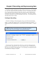
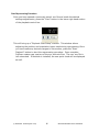
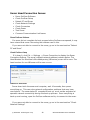
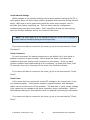
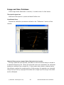
1
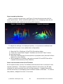
BV5000 User Handbook
Part Number: 202882-01
Revision: A
Updated: April 2010
©BlueView Technologies, Inc. All rights reserved.
All product names are trademarks of their respective companies.
www.blueview.com
BlueView Technologies has made every effort to ensure the
accuracy and completeness of this document; however, because
ongoing development efforts are made to continually improve the
capabilities of our products, we cannot guarantee the accuracy of
the contents of this document. We disclaim liability for errors,
omissions, or future changes herein.
The accompanying Software and Documentation are proprietary
products owned by BlueView Technologies, Inc., and protected
under U.S. and international copyright law. Except as authorized
under this License Agreement, the Software may be used only on
computers owned, leased, or otherwise controlled by you. You may
not reverse assemble, reverse compile, or otherwise translate
ProScan.
Copyright © 2003-2010 BlueView Technologies Corp. All rights
reserved. No part of this publication may be copied, reproduced, or
translated, without the prior written consent of BlueView
Technologies. No part of this publication may be stored or
transmitted in any electronic form without the prior consent of
BlueView Technologies. Any unauthorized use is a violation of
copyright laws. ProScan® is a registered trademark of BlueView
Technologies Corp.
© BlueView Technologies Corp
2
BlueView BV5000 User Handbook
Table of Content
Chapter 1 Introduction ................................................................ 5
System Contents ...................................................................................... 5
System Overview ..................................................................................... 6
Typical 3D Point Cloud Collection Overview................................................... 7
Chapter 2
Software Installation............................................... 8
ProScan Installation .................................................................................. 8
Meshlab Installation .................................................................................. 8
Leica Cyclone ........................................................................................... 9
Chapter 3
System Assembly and Testing ............................... 11
Assembling the Hardware ........................................................................ 11
Connect Components .............................................................................. 12
Installing the Pan and Tilt Drivers ............................................................. 13
Setup PC IP Address ............................................................................... 16
Connect to the BV5000............................................................................ 17
Installation of the Pan & Tilt Unit .............................................................. 18
Chapter 4 ProScan Software Basics ........................................... 20
Typical ProScan Screenshot...................................................................... 20
Image Display........................................................................................ 21
Toolbar ................................................................................................. 22
Toolbar ................................................................................................. 23
Range Controls....................................................................................... 24
Range and Bearing ................................................................................. 24
Playback Controls ................................................................................... 25
Settings/Sonar Control ............................................................................ 26
Manual Image Calibration ........................................................................ 27
Pan and Tilt Controls ............................................................................... 28
Screen Information ................................................................................. 29
Scan Setup ............................................................................................ 30
Chapter 5 Recording and Reprocessing Data ............................. 33
Configure Recording................................................................................ 33
Scan Intensity Files (.son) ....................................................................... 34
3D Point Cloud Files (.xyz & .off) .............................................................. 34
Sonar Settings File (.txt) ......................................................................... 35
© BlueView Technologies Corp
3
BlueView BV5000 User Handbook
Reviewing Data ...................................................................................... 35
Reprocessing Saved Data ........................................................................ 35
Chapter 6
System Troubleshooting ........................................ 37
Sonar + Pan & Tilt Connection Issues ........................................................ 37
Pan & Tilt Connection Issues .................................................................... 37
Sonar Head Connection Issues ................................................................. 40
Image and Scan Problems ....................................................................... 43
BlueView Customer Support ..................................................................... 45
Chapter 7
Appendix A
System Specifications............................................ 46
Typical Installation Configurations ..................... 47
Typical Tripod and Fixed Configurations ..................................................... 47
Typical ROV Configuration........................................................................ 48
Appendix B
System and Cable Diagrams ................................ 49
Sonar / Pan and Tilt Cable ....................................................................... 49
Pan and Tilt Outline Drawing .................................................................... 50
MB2250-45 Outline Drawing..................................................................... 51
MB1350-45 Outline Drawing..................................................................... 52
© BlueView Technologies Corp
4
BlueView BV5000 User Handbook
Chapter 1 Introduction
The BV5000 is a 3D mechanical scanning system that combines the data quality
of BlueView’s high-frequency microbathymetry sonar with the ease of use of
traditional 2D scanning sonar. This manual covers setup, installation, operation,
and technical specifications of BlueView’s 3D mechanical scanning sonar system.
When ordered, the BV5000 ships with either a 1.35 or 2.25 MHz sonar head, which
are both covered in this manual. For specific details on individual sonar head
specifications, see the specifications tables listed in the specification section of this
manual.
System Contents
Verify that your delivered system includes the following components:
•
Sonar Head
•
Pan & Tilt Unit
•
Sonar, Pan & Tilt Junction Box
•
Shipping Case, BV-5000
•
Hex Driver
•
Cable, Cat5, Ethernet
•
Cable, USB
•
Cable, Power
•
Proscan CD w/ Meshlab
•
USB Driver CD
•
Test Cable, 15 ft.
•
BV5000 User’s Handbook
© BlueView Technologies Corp
5
BlueView BV5000 User Handbook
System Overview
Through mechanical rotation of the sonar head, the BV5000 is capable of
producing 3D point clouds from a stationary location. Some of the more common
delivery methods (tripods and ROVs) are shown in the figures below. Notice the
volumetric scan zones around the sonar. With each scan, a large amount of high
resolution 3D data is collected.
The system works by mechanically scanning a thin vertical sonar slice around
the selected area as shown in the figure below. At each direction, a profile of the
surface is taken and added to the other direction profiles to create a final 3D point
cloud similar to the one shown below.
© BlueView Technologies Corp
6
BlueView BV5000 User Handbook
Typical 3D Point Cloud Collection Overview
This section provides a quick overview of a typical collection process.
Deploy the System
Position the BV5000 into the desired scan location. For tripod type systems,
verify that sonar is upright by viewing proper movement of the bottom imagery as
the sonar is tilted up and down using the pan and tilt controls.
Set Sound Speed
Open the File/Settings/Sonar Controls menu and enter the measured or
estimated sound speed of water for the scan location.
Image Calibration
To calibrate the image, first make sure that the sonar is thermally stabilized to
the ambient water temperature, then use the pan and tilt controls to point the
sonar so that its beam is grazing a relatively flat surface as described later in this
manual. Press the auto-calibration icon, then visually assess the calibration.
Enter Scan Parameters and Start Scan
Select the “Scan” button located under the pan and tilt controls to bring up the
“Scan Controls” window. Setup the desired scan process and enter any position
and orientation data available (not required). Press “Start Scan” to begin the scan
process. Depending on how the scan is configured, scans can take between 1-18
minutes to complete.
Monitor Scan Process
ProScan visually shows the intensity map (copper) and the selected point cloud
surfaces (blue) the current ping position. ProScan also brings up a status window
for the current scan. No 3D imagery is available until the scan is complete.
Point Cloud Viewing and Measurements
Use a point cloud viewer to spin the 3D point cloud around and view from
different angles. Take point to point measurements to make accurate distance
and size measurements. Once such viewer, MeshLab, is supplied with your
BV5000 system. All measurements are in meters.
Advanced Data using Cyclone
If required, use a third party software such as Cyclone by Lieca Geosystems to
perform advanced cleaning, registration, and modeling functions on the data.
© BlueView Technologies Corp
7
BlueView BV5000 User Handbook
Chapter 2
Software Installation
Your mechanical scanning system includes a disk containing BlueView’s ProScan
sonar software, as well as Meshlab, a point cloud viewing program. For proper
system testing and operation, ProScan and Meshlab should both be installed on
your collection PC. Cyclone by Leica Geosystems is sold separately.
ProScan Installation
To install ProScan, insert the ProScan CD into your computer’s CD-ROM drive
and follow the instructions to complete the installation. You may also launch the
installation by double clicking on “setup.exe” in the CD’s root directory.
When ProScan starts, if a personal firewall is enabled, a warning message may
pop up saying that ProScan is attempting to connect to the network. BlueView
recommends selecting the option that will always allow ProScan to access the
network (which it needs to do to communicate with sonar).
ProScan Software System Requirements
ProScan requires a system that meets or exceeds the following requirements for
optimum performance.
•
Windows 2000, XP, or Vista operating system
•
Dual-Core 1.8 GHz or faster processor
•
1GB or more of RAM
•
2GB or more of free disk space
•
CD-ROM drive for installation
•
1 Ethernet Port and 1 USB Port
Meshlab Installation
The installer for Meshlab, a 3D point cloud viewer and measurement package, is
included on the ProScan CD. To install Meshlab, just double click the
Meshlab_v121.exe file. Follow the instructions and accept the default options to
complete the installation. Refer to Help menu in Meshlab for operational
information.
© BlueView Technologies Corp
8
BlueView BV5000 User Handbook
Leica Cyclone
Note: The Cyclone software package is sold separately from the base BV5000
package. Contact BlueView sales for more information on obtaining trial and
permanent licenses for the Cyclone software package.
Cyclone by Leica Geosystems is a point cloud manipulation software package
that provides advanced operations such as cleaning, registering scans from
several locations, and modeling engineering objects for output to standard cad
products. BlueView sells the Cyclone package as an optional software accessory
for those requiring this type of package.
Software Options
Cyclone is originally installed with only its Viewer functionality enabled. By
purchasing additional licenses, some of the more advanced features can be
activated for use. The table below outlines some of the different features
associated with the different license options available.
Cyclone
Viewer
Cyclone
Register
Cyclone
Model
X
X
X
Measurement
X
X
Data Cleaning
X
X
Insert Reference Points
X
X
Insert Reference Surface
X
X
Global & Local Registration
X
Feature
Point Cloud Viewing
Advanced Modeling (from catalogs)
X
Point Cloud Export
X
X
CAD Export
X
X
© BlueView Technologies Corp
9
BlueView BV5000 User Handbook
Cyclone Installation Instructions
1. The Cyclone software installation files can either be downloaded directly
from the Lieca Geosystems website or found on CDs that come you’re your
purchased Cyclone software suite.
2. Install Cyclone and take note of the installation directory.
3. If you either requested a trial license, or purchased a permanent license, a
license file should have been provided to you as a file named “license.dat.”
4. Copy this file into the installation directory.
5. Launch Cyclone. A dialog should appear outlining the available licenses and
expiration dates.
6. If the available licenses do not appear in the dialog, the individual licenses
may need to be activated in the “License Manager” from the Help dropdown
in the Navigator window.
© BlueView Technologies Corp
10
BlueView BV5000 User Handbook
Chapter 3
System Assembly and Testing
Assembling the Hardware
1. Attach the sonar into the sonar clamp by loosening the four cap screws,
sliding in the sonar and retightening the four cap screws.
NOTE: The sonar is inserted into the clamp such that its connector is on the same
side as the Pan & Tilt connector.
1. 4X CAP
SCREWS FOR
CLAMP
2. SONAR
CONNECTOR
NOTE
ORIENTATION OF
SONAR
3. PAN &
TILT
CONNECTOR
REFER TO THE
PAN & TILT
INSTALLATION
SECTION FOR
MOUNTING
INSTRUCTIONS
NOTE: Use the stickers, side indicators, and connector placement on the
rear end cap of the sonar to determine the up-down orientation of the sonar.
If the sonar is inverted be sure to select the “inverted” option in ProScan’s
settings.
© BlueView Technologies Corp
11
BlueView BV5000 User Handbook
Connect Components
The BV5000 Package comes complete with everything needed to bench-test
and tank test your system.
1. Connect the sonar and Pan & Tilt unit to the control box using the SPT
(Sonar / Pan & Tilt) test cable. Connect the Ethernet cable to the control
box, then to an available network connection port on the PC. Verify that all
connections in the diagram below have been made.
2. Once all the connections are made, connect the SPT Junction Box to an AC
Power supply
© BlueView Technologies Corp
12
BlueView BV5000 User Handbook
Installing the Pan and Tilt Drivers
The SPT junction box contains a USB to RS-485 converter. The converter will
add a COM port to the PC for communicating with the pan and tilt. The drivers for
the converter need to be installed onto the PC. These drivers are located on the
“COMMFRONT USB Serial Adapter” CD included with the mechanical scanning
system.
There are two drivers to install: one is for a “USB Serial Converter” and the
other is for a “USB Serial Port.”
NOTE: Two separate “Found New Hardware Wizard” windows will pop up. Do not
close the second install wizard while installing the first.
NOTE: For Windows Vista, disconnect your PC from the internet before
installing drivers; otherwise, Windows Vista will search for and install the
drivers automatically from Windows Updates and cause errors. The
instructions below are for Windows XP. Installation for Windows Vista may
vary from the instructions below.
1. Connect the USB port on the control box to an available USB port on the PC.
The “Found New Hardware Wizard” will guide you through the installation process.
2. First, the USB Serial Converter driver will install. When prompted to use
Windows Update to search for the driver select “No, not this time” and click
“Next.”
© BlueView Technologies Corp
13
BlueView BV5000 User Handbook
3. Select “Install from a list or specific location” to install the driver from CD and
click “Next.”
4. Select “Search for the best driver in these locations” and check the box of
“Search removable media (floppy, CD-ROM…)”. Then click on the “Next” button.
5. When the driver is successfully installed the following window will pop up.
Click “Finish” to complete the installation of the first driver.
© BlueView Technologies Corp
14
BlueView BV5000 User Handbook
6. The 2nd “Found New Hardware” window will pop up prompting the driver
installation for “USB Serial Port”. DO NOT CLOSE THIS WINDOW! When
prompted to use Windows Update to search for the driver select “No, not this
time” and click “Next.”
7. Repeat steps 3-5 from above.
8. To confirm the drivers are installed successfully, check the Windows Device
Manager (in Windows XP, go to the Control Panel Æ Performance and Maintenance
Æ System, click the Hardware tab, then the Device Manager button). Take note of
the COM port number assigned to the USB COM port.
To access the Windows Device Manager click “Start” then RIGHT CLICK on
my computer in the start menu and select “Manage”. Click on “Device Manager”
in the left panel. Expand “Ports (COM and LPT)” and “Universal serial bus
controllers”. A new “USB Serial Port” should appear in the “Ports” section and a
“USB Serial Converter” should appear in the “Universal serial bus controllers”
section.
© BlueView Technologies Corp
15
BlueView BV5000 User Handbook
Setup PC IP Address
The IP address on the interface PC will need to be set to a static IP: 192.168.1.3.
Windows XP
To access a PC’s IP address in Windows, click Start Æ Control Panel Æ Network
Connections and double click on the computer’s Ethernet port (usually Local Area
Connection 1). Right click and select ‘Properties’ then double click on ‘Internet
Protocol (TCP/IP)’ in the list of components. Make sure the IP address is set as
shown below:
Windows Vista
To access a PC’s IP address in Windows Vista, click Start Æ Control Panel Æ
Network and Internet Æ Network and Sharing Center Æ Manage network
connections.
Right click the connection that should be changed, and click Properties. You
may be asked for an administrator password.
Click the Networking tab. Under This connection uses the following items,
click Internet Protocol Version 4 (TCP/IPv4), then click Properties.
As described in the previous section, set the IP address to 192.168.1.3, and the
subnet mask to 255.255.255.0.
© BlueView Technologies Corp
16
BlueView BV5000 User Handbook
Connect to the BV5000
After ProScan is installed and the PC configured, it’s time to connect to the
system. Open the ProScan Software and click on the connect button, as shown
below.
Note: that if the sonar has just received power, it will take ~30 sec to boot
and be ready for a connection.
Connect
When the connect button is pressed, ProScan should connect automatically to
the sonar and the pan & tilt. If ProScan does not find the sonar or pan & tilt, look
at the troubleshooting section of this manual.
© BlueView Technologies Corp
17
BlueView BV5000 User Handbook
Installation of the Pan & Tilt Unit
When mounting the Pan & Tilt Unit to either a tripod, ROV or other structure the
orientation of the base plate must be noted. The base plate contains a 4 bolt hole
pattern of 3.5” diameter which accepts ¼”-20 sized screws. The unit also has an
external mechanical stop which must be installed after the unit is mounted. The
use of this mechanical stop requires two different types of screws when mounting
the base plate to the structure: 3 x ¼”-20 Button Head Cap Screws and 1 x ¼”20 Socket Head Cap Screw.
1. Connect to the Pan & Tilt via ProScan and send the unit to
the “Home” Position. The “Home” position is at the center of
rotation of the “Pan” axis. Scans will be centered about this
position. If mounting onto an ROV, the Pan and Tilt should be
mounted with the “Home” position pointed directly away from
the ROV.
2. Mount the base plate with the Socket Head Cap Screw on the OPPOSITE
side of the connector when the Pan and Tilt is in the “Home” position. Use the
Button Head Cap Screws at the other three locations.
Socket Head
Cap Screw
Connector
© BlueView Technologies Corp
18
BlueView BV5000 User Handbook
3. With the unit still in the “Home” position, loosely attach the stop collar.
Align the sliding nut and bolt such that it is centered in the slot. Next, align that
bolt with the Button Head Cap Screw which is directly under the connector. Adjust
the height of the stop collar so the head of the “sliding” bolt is just above the
Button Head Cap Screw. Tighten the stop collar onto the Pan & Tilt unit.
CENTERED IN
SLOT WITH
NUT ON TOP
HEADS
ALIGNED
4. Using the controls in ProScan, verify the Pan and Tilt can rotate from -180
degrees to +180 degrees in the Pan axis. The head of the sliding bolt should
come in contact with the head of the Socket Head Cap Screw and slide in
the slot.
© BlueView Technologies Corp
19
BlueView BV5000 User Handbook
Chapter 4 ProScan Software Basics
BlueView’s ProScan software is the main user interface for setting up and
running a 3D scan operation. While ProScan can output 3D point cloud files in
several formats, it does not work directly with 3D data sets. For viewing and
manipulation of 3D data, see the following chapters regarding working with point
clouds.
Typical ProScan Screenshot
Toolbar
Range
Controls
Range and
Bearing
Pan and Tilt
Controls
Image
Display
© BlueView Technologies Corp
20
BlueView BV5000 User Handbook
Image Display
The imagery shown in the sonar window has reflects two types of data. First,
the full intensity map for each ping is displayed in a copper color map. Overlaid
on top of the intensity map is the range value chosen for each angle for use in the
creation of 3D point clouds. This range data shows up in blue. The range data is
chosen using a threshold routine and the threshold value set in the
File/Settings/Sonar Controls window. If no data in a given angle bin meets the
threshold requirement, no blue is shown and no point is assigned in the point
cloud for that angle.
Copper
Intensity Map
Blue Range
Data
© BlueView Technologies Corp
21
BlueView BV5000 User Handbook
The sonar collects line data in a vertical orientation and that line data is
displayed in ProScan. The following diagrams illustrate how to interpret the
image display as well as how the line data translates to the point cloud.
Clockwise from upper left: Illustration of the multibeam collection, display of
the line data in the copper color map, display of the blue threshold data points,
display of the point cloud.
© BlueView Technologies Corp
22
BlueView BV5000 User Handbook
Toolbar
The toolbar provides quick access to several commonly used sonar functions.
Connecting to a Sonar
To connect to a sonar, simply click the connect icon on the toolbar. This will
connect to the sonar at the network address specified in the Sonar Connection
dialog.
Opening a
File
This allows the user to select a sonar file (.son) to open. Both playback and
network output begin automatically.
Network Transmit
This function is not used with the BV5000 setup
New File
This function is not used with the BV5000 setup
Automatic Image Calibration
This will perform an automatic Image
Calibration. To calibrate the image,
first make sure that the sonar is
thermally stabilized to the ambient
water temperature then click the icon.
A dialog box will be displayed to provide
an example of the recommended
configuration. Ensure the sonar is
pointed at an appropriate target. If an
appropriate target is not available
Manual Calibration is available and
discussed later in this manual.
Automatic Image Calibration will occur
after clicking OK.
© BlueView Technologies Corp
23
BlueView BV5000 User Handbook
Length Measurement
After clicking the length measurement icon in the toolbar, click the location
where you want to start the measurement. ProScan then draws a dotted line
between that point and the mouse cursor. Click a second time to freeze the
current measurement. A third click sets the starting point for a new measurement.
The length of the dotted line is displayed just to the left of the cursor location in
the lower right of the ProScan window. To clear the measurement line, press the
Measurement button a second time or right-click the mouse.
Range Controls
The sonar range sliders (along the left side of the ProScan window) allow you to
change both the start and stop range (both are measured in meters). The stop
range selects how far out the sonar is looking whereas the start range selects
where the sonar starts acquiring data. By using both controls you can zoom in on
a target. The range settings also control the data window that line data is derived
from, allowing a user to choose a specific zone to extract line data from.
Range and Bearing
The current range (meters) and bearing (degrees) of the cursor is displayed in
the lower right corner of the ProScan window.
© BlueView Technologies Corp
24
BlueView BV5000 User Handbook
Playback Controls
When a file is loaded, the playback controls appear at the bottom of the
window. The table below describes the different controls available. Also available
between the previous ping and next ping buttons is the time slider. It shows the
current location inside the file. You may click on it to jump to a new location or
simply drag the marker back and forth to quickly scan through a file.
Function
Icon
Description
Pause
Pause playback at the current ping
Play
Resume playback
Previous Ping
Go to the previous ping
Next Ping
Go to the next ping
© BlueView Technologies Corp
25
BlueView BV5000 User Handbook
Settings/Sonar Control
The only tabs of the Settings window you need to adjust when using the
BV5000 are the Sonar Controls tab and the Scan Settings tab. The Settings
window is accessible by clicking File Æ Settings. The Scan Settings tab is
discussed later in this manual.
Range Threshold Level controls
The Range Threshold controls the value at which a target will be recognized.
The allowed values range from 100 to 20,000. The default value is 250, and
values typically range from 100 to 500.
Sound Velocity
This is the sound velocity (in meters per second) used to compute target range.
Override recorded Sound Velocity
To replace the recorded Sound Velocity with the displayed value when playing
back a .SON file, click this box.
© BlueView Technologies Corp
26
BlueView BV5000 User Handbook
Manual Image Calibration
Select the File/Image Calibration menu item to bring up the Image Calibration
dialog box. An automated calibration can be performed using the Auto-Calibration
icon on the desktop discussed earlier in this chapter.
The sonar contains two arrays that must be calibrated to synchronize the
imagery between them. To calibrate the image, first make sure that the sonar is
thermally stabilized to the ambient water temperature, then use the pan and tilt
controls to point the sonar so that its beam is grazing a relatively flat surface,
such as a piling or the seafloor, and displaying a diagonal line across the image
display.
If the diagonal line has a break in it, as shown in the left-hand figure below,
bring up the Image Calibration dialog box, and move the slider until a single,
unbroken line is displayed. Click OK to save the calibration value.
© BlueView Technologies Corp
27
BlueView BV5000 User Handbook
Pan and Tilt Controls
If the Pan/Tilt is connected and properly configured, the Pan/Tilt controls appear
on the right side of the screen.
Use the directional buttons to move the pan and tilt.
Home Position
The Pan/Tilt Home position is defined as the center rotation angle for each axis.
To move to the ‘Home’ position, click the corresponding button.
Start Scan
Start Scan
Rotational scans are performed by clicking the Start Scan button on the Pan/Tilt
control panel or by clicking File Æ Start Scan. Both Single Scans and Spherical
Scans can be performed from the Scan Setup window.
© BlueView Technologies Corp
28
BlueView BV5000 User Handbook
Screen Information
Several Text Boxes are located around the sonar image to provide additional
information both in live operation and file playback modes.
Ping Rate
While the screen update rate is only on the order of 2 images a second, many
more imagers are being process in the background to create high-resolution 3D
point clouds. The ping rate display represents the rate that ProScan is collecting
data in the background.
Time Stamp
This is the time stamp for the current ping / image
Sonar Type
This message lets you know if you are looking at live or saved data. It also
gives you information regarding which sonar created the current sonar data.
Sound Speed
This message displays the sound speed currently being used for image processing.
This value is adjustable in the File/Settings/Sonar Controls window.
© BlueView Technologies Corp
29
BlueView BV5000 User Handbook
Scan Setup
Rotational scans are performed by clicking
File Æ Start Scan or the Start Scan button on
the Pan/Tilt control panel. Both Single Scans
and Spherical Scans can be performed. All
settings for a single scan can be set in the
Scan Setup window. Additional settings for
Spherical Scans are located in the Settings
window (File Æ SettingsÆ Scan Settings.)
Running Single Scans
The term “single scan” refers to a scan
collected at a single tilt angle. To run a single
scan, first move the sonar to the desired tilt
angle, then check the Single Scan box, set the
desired Scan Speed and Total Pan Angle, and
click Start Scan. A progress window will
appear, while the scan is running.
Running Spherical Scans
Spherical scans allow a greater volume to be
scanned in a single operation. Spherical scans
are created by taking several overlapping
scans at different tilt angles. The Total Pan
Angle and Center Scan option are applicable to
spherical scans as well.
© BlueView Technologies Corp
30
BlueView BV5000 User Handbook
Spherical scan settings are located in the File\Settings File\Scan Settings
window. Spherical Scan can be setup for either 4 or 5 overlapping scans.
Selecting 4 scans provides a 15 degree overlap between the scans, while selecting
5 scans provides 22.5 degrees overlap between scans. The final scan at -45
degrees is optional. Click the Include final 45 degree scan box to include it. When
performing a scan from a tripod, this final 45 degree scan is pointed sharply at the
seafloor and may not be of interest. Eliminating this final scan decreases the time
necessary to perform a spherical scan.
Total Pan Angle
Both single and spherical scans can both be set to a specific sector size. There
are many situations when scans less than 360 degrees are adequate, speeding up
the scan process significantly. These controls allow you to set the total pan angle
for the upcoming scan.
Scan Speed
Adjusting the scan speed allows the user to sacrifice point cloud density for
faster scan rates. This setting is adjustable between 1 and 10 degrees per
second, with 1 deg/sec providing the highest density point clouds.
Center Scan Angle
By default, the scan is centered about the Home position. If you want the scan
centered at the current pan position, check the “Center Scan(s) at current pan
angle” checkbox.
Note that if the selected Total Pan Angle will hit a pan angle limit (less than 180, greater than 180), then the start and stop angles will be adjusted so that the
total scan angle is still obtained. That is, if this option is checked when the current
© BlueView Technologies Corp
31
BlueView BV5000 User Handbook
pan angle is -180, and a 360 degree total scan angle is also selected, the scan will
not be centered at -180, but will scan 360 degrees from -180 to 180 degrees.
File Controls
When conducting Spherical Scans the combined Merged File Name can be
assigned in the Scan Setup dialog box. This file name overrides the default name.
Position and Orientation Input
If the orientation and position of the BV5000 unit are known, that data can be
entered in the Scan Setup dialog box. The exported point could files are adjusted
such that the Z axis normal to the earth’s surface and the X axis is oriented north.
© BlueView Technologies Corp
32
BlueView BV5000 User Handbook
Chapter 5 Recording and Reprocessing Data
By default, ProScan produces four types of files for each scan, a .son intensity
file, .xyz and .off point cloud files as well as a .txt file. The intensity files allow
you to reprocess the raw data at a later time, while the point cloud files allow
viewing the scan results in standard point cloud viewers. The .txt file contains
information pertaining to the sonar settings for that scan. The following section
describes these items in detail.
Configure Recording
Click File Æ Settings Æ Recording tab to bring up the File Recording Setup
dialog. To enable data logging check “File Recording Enabled” and press OK. To
change where files are saved type in a new location or click “Browse…” to select
one.
NOTE: Data files are automatically stored in C:\Documents and Settings
\Username\Temp. This can be changed in the Recording Setup dialog.
Checking the “Save Individual Scan Files” box in the Scan Settings tab will
preserve the files generated for each of the individual scans of a Spherical Scan
after they are merged as described later. If not checked, the individual files will
be deleted after merging is complete.
© BlueView Technologies Corp
33
BlueView BV5000 User Handbook
Scan Intensity Files (.son)
A .SON file is output for each of the individual scans in a Spherical Scan. When
the Spherical Scan is completed, the individual files will be combined into a single
.SON file. The combined file will have the name entered in the "Merge File Name"
field with a suffix of "_complete" automatically appended. If no filename was
entered in the field, then the name of the first scan will be used. The individual
.SON files and 3D Point Cloud files will also be renamed with that name, but with
their tilt angle appended.
3D Point Cloud Files (.xyz & .off)
As descried above, .SON files are automatically created during scans. 3D Point
Cloud files are also created automatically, with the same names as the .SON file.
Two kinds of 3D Point Cloud files are created: XYZ files, with the extension “.xyz”,
and OFF files, with the extension “.off”.
Both kinds of 3D Point Cloud files are in ASCII format and represent 3D points
using X, Y, and Z coordinates. The X and Y values are in meters from the sonar
and are laid out on a Cartesian grid with the sonar at the origin (X = 0, Y = 0).
The Z values that are higher (shallower) than the sonar have positive values, and
Z values lower (deeper) than the sonar have negative values. If a depth value is
provided as described in the Geo-referencing section below, then Z values deeper
than the water surface have negative values, effectively moving the origin to the
surface.
© BlueView Technologies Corp
34
BlueView BV5000 User Handbook
XYZ files contain only three values, separated by spaces. OFF files have a twoline header, followed by a line for each 3D point. Each of these lines has the X,Y,
and Z values, followed by the color assigned to that point, expressed as RGBA.
Each of the X,Y,Z, and RGBA values are separated by spaces.
The color map used assigns blue to the deepest points and red to the shallowest
points. Meshlab and other 3D viewers use this color map to display the points.
Sonar Settings File (.txt)
The .txt file which is created contains information pertaining to the sonar and
scan settings for that scan. The following information is logged: Date and time,
sound speed, calibration setting, TVG, gain, sonar type, threshold setting, physical
offsets and the comments field.
Reviewing Data
When Meshlab is installed and the “Run Meshlab after each scan” box is
checked (File Æ Settings Æ Recording tab), the OFF file is opened and the 3D
point cloud file can be reviewed.
Reprocessing Saved Data
As previously noted, one of the unique aspects of the BV5000 system is the
ability to store raw scan data and reprocess this data at a later time. Some of the
reasons to reprocess raw data are to:
1) process with corrected sound speed
2) process with different threshold settings
3) process with proper calibration
4) process with accurate position and orientation data
5) range gate the data
Even with the most careful procedures, mistakes can be made in the field. With
the ability to fix these problems at a later stage of a project, a significant amount
of time and money can be saved.
© BlueView Technologies Corp
35
BlueView BV5000 User Handbook
Data Reprocessing Procedure
Once you have opened a previously saved .son file and made the desired
settings adjustments, press the “Scan” button in the lower right hand section
of the playback control bar.
This will bring up a “Playback Scan Setup” window. This window allows
adjusting the position and orientation inputs used during reprocessing. Once
you have made any desired changes to this section, press the “Start
Playback” button to start the reprocessing procedure. Once complete,
ProScan creates new versions of the xyz and msh files. The raw .son file is
left untouched. If MeshLab is installed, the new point cloud will be displayed
as well.
© BlueView Technologies Corp
36
BlueView BV5000 User Handbook
Chapter 6
System Troubleshooting
This section is designed to help you quickly identify and solve issues dealing
with the inability to connect the BlueView 3D scanning system from a PC. While
the basic connections between the system and computer are straight forward,
things can get very confusing once integrated into a delivery system. The
following approach attempts to test different potential causes in a way that
optimizes the debugging process.
Sonar + Pan & Tilt Connection Issues
The Sonar Head and Mechanical Pan & Tilt components run on nearly
independent but parallel networks. Each component has its own connector and
conductor sets for communications all the way back to the computer. This can
help isolated problems quickly since the only items shared are the DC power
supply, DC power lines, and SPT Cable. Try running through the individual
troubleshooting components described further in this chapter.
Pan & Tilt Connection Issues
•
•
•
•
•
•
•
Connect with Test Cable
Change USB Ports
Verify USB Com Port
Reinstall P&T Drivers
Verify Auto-Pan/Tilt
Check Connectors
Check Power
Connect with Test Cable
If you are having trouble running the pan & tilt through a longer field cable or
an ROV system, hook the supplied test cable up between the pan & tilt and the PC.
If you are able to connect with the test cable, then the PC is configured properly
and the pan & tilt is probably working fine.
If you were not able to connect to the pan and tilt, go on to the next section
“Change USB ports”
© BlueView Technologies Corp
37
BlueView BV5000 User Handbook
Change USB ports
Change the USB port used for this connection on the PC.
If you were not able to connect to the pan and tilt, go on to the next section
“Verify USB Com Port”
Check Auto-Pan/Tilt
Verify that the ProScan “File/Settings/Pan/Tilt/Auto Connect to Pan/Tilt” option
is selected. Once selected, try to reconnect to the pan and tilt using the
“File/Connect to Pan/Tilt” menu item.
If you were not able to connect to the pan and tilt, go on to the next section
“Verify USB Com Port”
Verify USB Com Port
The pan and tilt connects to the PC through a USB-to-RS485 converter located
in the SPT box. When the USB connection is made, and all the drivers are
installed properly, this connection will show up in the “Device Manager/Ports (Com
and LPT)” as a USB Com Port. If you do not see the USB Com port listed in this
list, then either the device drivers are not installed properly, or the USB-to-RS485
converter is not functioning properly.
If you were not able to connect to the pan and tilt, go on to the next section
“Reinstall Drivers”
© BlueView Technologies Corp
38
BlueView BV5000 User Handbook
Reinstall Drivers
Try reinstalling the drivers. Refer to the “ Installing the Pan and Tilt Drivers”
section in this manual.
If you were not able to connect to the pan and tilt, go on to the next section
“Reinstall Drivers.”
Verify Com Port Settings
Verify the Com Port Settings. They should be set as follows: 9600 baud, 8
data bit, parity none, 1 stop bit, no flow control.
If you were not able to connect to the pan and tilt, go on to the next section
“Check Connectors.”
Check Connectors
It is not uncommon for topside connectors to get pulled out of their ports or
subsea connectors to get corroded. Power-down the system, and check the
condition and proper seating of all connectors in the system.
If you were not able to connect to the sonar, go on to the next section “Check
Power”
Check Power
If the sonar does not receive the correct DC voltage on the correct pins, it can
not operate properly. Faulty power supplies, tripped breakers, and damaged
cables can all be the source of this problem. The best way to verify proper voltage
is by measuring the voltage at the sonar connector using a multimeter. Refer to
the hardware manual using the detailed connector/pin information in Appendix A
of the is manual
© BlueView Technologies Corp
39
BlueView BV5000 User Handbook
Sonar Head Connection Issues
•
•
•
•
•
•
•
•
Rerun ProScan Software
Check ProScan Setup
Reboot PC and Sonar
Check Network Settings
Check Connectors
Check Power
Test Sonar
Common Communication Link Issues
Rerun ProScan Software
If a sonar did not complete its boot process before ProScan was opened, it may
have missed that sonar. Rerunning the software can fix this.
If you were not able to connect to the sonar, go on to the next section “Reboot
PC and Sonar”
Check ProScan Setup
If it doesn’t, click File -> Settings -> Sonar Connection to display the Sonar
Connection Options. The sonar’s default network address is shown below. The
Head Number for BlueView’s MicroBathymetry (MB series) sonar will be zero. The
head number for non-MB sonar will be zero or one.
Reboot PC and Sonar
Power down both the sonar and computer, wait 10 seconds, then power
everything up. This can solve network configuration problems that may have
come about. The sonar takes 35 seconds to boot up, so do not be surprised at
sporadic network connectivity during this boot up process. Once everything is
back up and running, open the ProScan software and try to connect to the sonar.
If you were not able to connect to the sonar, go on to the next section “Check
Network Settings”
© BlueView Technologies Corp
40
BlueView BV5000 User Handbook
Check Network Settings
While changes to the network settings can be done without restarting the PC, a
quick power down can solve many network problems that can arise during network
setup. With that in mind, power down both the sonar and computer, wait 10
seconds, then power everything up. This can solve network configuration
problems that may have come about. Once everything is back up and running,
open the ProScan software and try to connect to the sonar.
NOTE: The sonar takes up to 35 seconds to boot up, so do not be surprised at
sporadic network connectivity during this boot up process.
If you were not able to connect to the sonar, go on to the next section “Check
Connectors”
Check Connectors
It is not uncommon for topside connectors to get pulled out of their ports or
subsea connectors to get corroded. Power-down the sonar, and check the
condition and proper seating of all connectors in the system. Once you have
verified condition and proper seating of all connectors, re-power the Sonar, wait
35 seconds, then try to reconnect to the sonar from ProScan software.
If you were not able to connect to the sonar, go on to the next section “Check
Power”
Check Power
If the sonar does not receive the correct DC voltage on the correct pins, it can
not operate properly. Faulty power supplies, tripped breakers, and damaged
cables can all be the source of this problem. The best way to verify proper voltage
is by measuring the voltage at the sonar connector using a multimeter. Refer to
the hardware manual for your specific sonar for detailed connector/pin information
If you were not able to connect to the sonar, go on to the next section “Check
Sonar”
© BlueView Technologies Corp
41
BlueView BV5000 User Handbook
Bench Check Sonar
In most cases, the cause of the problem is not a faulty sonar, but before you
start tearing apart your system integration looking for a problem, it is worth
taking a quick second to verify that the sonar is working properly. This is
accomplished by setting up a bench-top test using the test cables and AC
power supply that came with the sonar. This test will quickly tell us whether
the problem is with the sonar/PC or with the rest of the system. Use the
following instructions to setup and test your sonar. Refer to section “Connect
Components” in this manual for setup instructions.
© BlueView Technologies Corp
42
BlueView BV5000 User Handbook
Image and Scan Problems
If the image looks distorted or incorrect, it could be one of a few issues.
The tripod is tipped over
Make sure the tripod is in place and hasn’t fallen over.
Uncalibrated Sonar
Repeat the calibration procedure outlined in the “Calibration” section of this
manual.
Spherical Scan process stopped before final point cloud creation
During a spherical scan process, the data for each horizontal sweep is stored in
a separate temporary file. When all horizontal scans are completed, the individual
scans are combined into a single file. If the system shuts down or aborts before
the software reaches the merge portion of the process, the operator can manually
merge the xyz files by copying all the data into a single xyz file using a text editor
such as Notepad.
© BlueView Technologies Corp
43
BlueView BV5000 User Handbook
Sonar mounted upside down.
Figure 1 shows a normal scan, and Figure 2 shows the same scan with the
sonar upside down. When mounted upside down, the overlapping scans do not
overlay properly and a spherical smearing affect appears.
To adjust the settings on a deployed system, or re-process a rotational scan
acquired with the sonar in an upside down configuration:
1. Open the File Æ Settings Æ Pan/TiltÆ Orientation dialog.
2. Check the “Invert Beam Angles” checkbox and click the “Save” button.
For post processing
3. Open the rotational scan file and perform a playback scan (see the ProScan
manual for more details).
4. When playback is complete, new and corrected XYZ and OFF files will be
created in the directory of the .SON file.
Sonar is not mounted vertical in Pan/Tilt mount.
As the system scans a scene, the software assumes the sonar is mounted in the
vertical orientation. If the head is actually twisted in the mount, the 3D data
collected for each horizontal scan will not align properly. A jagged step along
vertical structures on overlapping scans would be visible in this case. To resolve
the problem, readjust the sonar in its mount.
© BlueView Technologies Corp
44
BlueView BV5000 User Handbook
Not enough scan overlap.
If a spherical scan isn’t dense enough, ProScan can be set to perform more
scans with more overlapping area for better viewing. These can be found in
ProScan’s settings, in the “Scan Settings” tab. See the ProScan manual for more
information.
Rotational speed set too high.
If increasing the scan overlap doesn’t improve image quality, it may be that the
scan speed is too high. This can be changed in the “Scan Setup” window. See the
ProScan manual for more information.
BlueView Customer Support
At this point, if you were able to connect to your BV-500, you can assume the
system is working properly and that the PC is set up correctly. The only thing left
is the communications link specific to your particular implementation/application.
It is advised that you get your system integrator involved at this point.
BlueView Technologies Customer Support
www.blueview.com
206-545-7260
8am to 5pm PST Mon through Fri
© BlueView Technologies Corp
45
BlueView BV5000 User Handbook
Chapter 7
System Specifications
BV5000-1350
BV5000-2250
Sonar Head Field-of-View
1⁰x45⁰
1⁰x45⁰
Pan Scan Angle Coverage
45⁰ - 360⁰
45⁰ - 360⁰
Tilt Scan Angle Coverage
-65⁰ - 65⁰
-65⁰ - 65⁰
Up to 40 Hz
Up to 40 Hz
1.35 MHz
2.25 MHz
Maximum Range
27m (90 ft.)
9m (30 ft.)
Number of Beams
256
256
Beam Width
1⁰ x 1⁰
1⁰ x 1⁰
Beam Spacing
0.18⁰
0.18⁰
1.23 in
0.74 in
10.5(L) x 9.2(W) x 15.4(H)
8.9(L) x 8.6(W) x 15.4(H)
Weight in Air
21.7 lbs
19.1 lbs
Weight in Water
8.2 lbs
6.0 lbs
300 m (1,000 ft.)
300 m (1,000 ft.)
45 W
45 W
120-240 VDC
120-240 VDC
Voltage Directly to Head (if SPT
box not used)
12-48 VDC
12-48 VDC
Voltage Directly to Pan & Tilt (if
SPT box not used)
20-29 VDC
20-29 VDC
Ethernet and RS485
Ethernet and RS485
50 Mbs
50 Mbs
192.168.1.45
192.168.1.45
9600 baud, 8 data bits, Parity
None, 1 Stop Bit, No Flow
Control
9600 baud, 8 data bits, Parity
None, 1 Stop Bit, No Flow
Control
.son, .off and .xyz files
.son, .off and .xyz files
meters
meters
Sonar
Update Rate
Frequency
Time Resolution
Mechanical
Size (L x W x H)
Depth Rating
Electrical
Power Consumption
SPT Junction Box
Communications
Required Com Channels
Ethernet Bandwidth
Sonar IP Address
RS485 Settings
File Output Types
Data Output Formats
Data Output Units
© BlueView Technologies Corp
46
BlueView BV5000 User Handbook
Appendix A
Typical Installation Configurations
Typical Tripod and Fixed Configurations
© BlueView Technologies Corp
47
BlueView BV5000 User Handbook
Typical ROV Configuration
Fiber to
Ethernet
Converter
RS485 USB
Converter
User Computer
RS485 Mux
Customer Potted
Connection
BlueView Supplied Whip
(Sonar to Customer Whip)
Function
BV5000 Head
Sonar
Pin
4
Blue and
Blue/White
Ground
7
Brown and
Brown/White
Ethernet
Rx+
1
Orange/White
Ethernet
Rx-
2
Ethernet
Tx+
Ethernet
Tx-
Customer
Supplied
Whip
RO
1248 VDC
RS485
Ground
Whip Cable
Color
12-48 VDC
ROV Console
Fiber
Ethernet
to Fiber
Converter
Fiber
Function
RJ45
Pins
Ethernet Rx+
1
Orange
Ethernet Rx-
2
3
Green/white
Ethernet Tx+
3
6
Green
Ethernet Tx-
6
Note: Try a straight Ethernet connection first. Then try
a crossed connection (swap 1&3 , 2&6)
Pan & Tilt
© BlueView Technologies Corp
48
BlueView BV5000 User Handbook
Appendix B
System and Cable Diagrams
10 Pin Connector to Sonar (Impulse MKS310-CCP-RA)
Sonar / Pan and Tilt Cable
Pin
Function
1
Ethernet RX+ (to sonar)
2
Ethernet RX- (to sonar)
3
Ethernet TX+ (to sonar)
4
+24V DC
5
+24V DC
6
Ethernet TX- (to sonar)
7
Ground
8
Ground
9
N/C
10
N/C
4 Pin Connector to Pan & Tilt Unit (Impulse LPMIL-4FS)
Pin
Function
1
DC Common
2
+24V DC
3
Data B
4
Data A
8 Pin Connector to Sonar and Pan & Tilt Unit (Souriau
UTG612-8PN)
Pin
Function
A
Ethernet RX+ (to sonar)
B
Ethernet RX- (to sonar)
C
Ethernet TX+ (to sonar)
D
+24V DC
E
24 DC Common
F
Ethernet TX- (to sonar)
G
Data A (to P&T)
H
© BlueView Technologies Corp
49
Data B (to P&T)
BlueView BV5000 User Handbook
Pan and Tilt Outline Drawing
Units: Inches
© BlueView Technologies Corp
50
BlueView BV5000 User Handbook
MB2250-45 Outline Drawing
Units: Inches
© BlueView Technologies Corp
51
BlueView BV5000 User Handbook
MB1350-45 Outline Drawing
Units: Inches
© BlueView Technologies Corp
52
BlueView BV5000 User Handbook