1
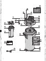
1 Definition of Terms
1
2
3
4
5
6
7
8
9
10
Pressure Vessel
Filter Cartridge
Pressure Vessel Lid
Connector Head
(optionally with Measuring Unit)
Display Unit (optional)
Inlet Hose
Inlet Valve on Inlet Hose (Chapter 12)
Terminal Device Connection
Flush Valve with Water Outlet
Connection of Outlet Hose
11
12
13
14
15
16
17
18
19
20
21
Filter Change Sticker
Kick Loops
Ejector Base
Display of the Display Unit (optional)
Lock
Mantle Handle
Reducer 1“– 3/4“
Transport Protective Cap
By-pass Screw
Lid Handle
Flush Hose
2 General Information
Before commissioning or replacing the filter, please read the system handbook for the PURITY Quell
ST Water Filter System. There you will find detailed information on operating and safety notes, maintenance, troubleshooting and technical data.
You will find instructions on how to flush the system in the PURITY Quell ST system handbook.
3 Commissioning a new filter with MDU (Measuring and Display Unit)
3.1 By-Pass Setting for Filter Systems with Measuring and Display Unit
•
Identify the local temporary hardness in gpg (grains per gallon) or rather mg/L (CaCO3 mg/l)
using the enclosed temporary hardness test.
•
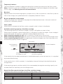
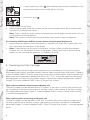
Check the by-pass setting on the by-pass screw 19 .
Note: A 30% by-pass setting has been made in the factory, and must be changed to suit the local
temporary hardness and the application (Chapter 7, system handbook PURITY Quell ST Water Filter
System).
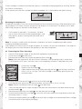
3.2 Commissioning the Filter Systems with Measuring and Display Unit
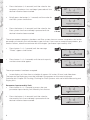
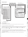
Representation in operating mode
Bar Display
Local Temporary
Hardness Set
14
30 %
gpg
1022
US
gaL
10.12.08
Available residual capacity
Date Field: Installation or
in US gallons
last filter change date
By-Pass Proportion
Flow Symbol
3