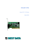
1
Smart One
DOCSIS Cable Modem
User's Manual
Model Number: CMX300
Warranty
One-Year Limited Warranty
The warranty described below is extended only to the original buyer and is not transferable.
1. Customer Obligations:
A. CUSTOMER assumes full responsibility that the product purchased and any copies of software included with it or licensed separately,
meet the specifications, capacity, versatilities and other requirements of the customer.
B. CUSTOMER assumes full responsibility for the installation and effectiveness of the operating environment in which the product and
software are to function.
2. Limited Warranties And Conditions Of Sale:
A. Manufacturer warrants that this product is free from all defects in materials and workmanship for one year from the date of purchase
from an authorized dealer.
B. Except as provided herein no employee, agent, franchise, dealer or other person is authorized to give any warranties of any nature on
behalf of manufacturer.
3. Repairs And Service:
A. In the event of malfunction or failure attributable directly to faulty workmanship and/or materials, the product should be taken to the
original authorized dealer it was purchased from or sent to manufacturer, along with proof of purchase and the return merchandise
authorization number (RMA) provided by manufacturer.
B. If the product is sent by mail or freight company, the purchaser agrees to pay shipping charges, insure the product or assume the risk
of loss or damage which may occur in transit, and to use a shipping container equivalent to the original packaging.
C. Once a product is returned, manufacturer will at its option, repair or replace the defective product or components, to whatever extent it
deems necessary to restore the product or component to proper operating condition.
D. Manufacturer shall not be liable for any damages caused by delay in delivering or furnishing equipment and/or software.
DOCSIS 1.0 Cable Modem User Guide Rev. 3.0
i
4.
ii
Limits Of Liability:
A. THE CUSTOMER SHALL BE SOLELY RESPONSIBLE FOR THE FAILURE OF THIS PRODUCT OR COMPONENT
THEREON, RESULTING FROM ACCIDENT, ABUSE, OR MISAPPLICATION OF THE PRODUCT, AND MANUFACTURER
ASSUMES NO LIABILITY AS A CONSEQUENCE OF SUCH EVENTS UNDER THE TERMS OF THIS WARRANTY.
B. WHILE MANUFACTURER HAS MADE EVERY EFFORT TO PROVIDE CLEAR AND ACCURATE TECHNICAL
INFORMATION ABOUT THE APPLICATION OF ITS PRODUCTS, MANUFACTURER ASSUMES NO LIABILITY FOR ANY
EVENTS ARISING OUT OF THE USE OF THE TECHNICAL INFORMATION.
C. ANY AND ALL IMPLIED WARRANTIES OF MERCHANTABILITY AND FITNESS FOR A PARTICULAR USE, SHALL
HAVE NO GREATER DURATION THAN THE PERIOD FOR THE EXPRESSED WRITTEN WARRANTY
APPLICABLE TO THIS PRODUCT AS SHOWN ABOVE, AND SHALL TERMINATE AUTOMATICALLY AT THE EXPIRATION
OF SUCH PERIOD.
D. NO ACTION SHALL BE BROUGHT FOR BREACH OF ANY IMPLIED OR EXPRESSED WARRANTY AFTER 30 DAYS
SUBSEQUENT TO THE EXPIRATION OF THE PERIOD OF THE EXPRESSED WRITTEN WARRANTY.
E. INCIDENTAL AND CONSEQUENTIAL DAMAGES CAUSED BY MALFUNCTION, DEFECT OR OTHERWISE AND WITH
RESPECT TO BREACH OF ANY EXPRESSED OR IMPLIED WARRANTY ARE NOT THE RESPONSIBILITY OF
MANUFACTURER, AND TO THE EXTENT PERMITTED BY LAW ARE HEREBY EXCLUDED BOTH FOR PROPERTY AND TO
THE EXTENT NOT UNCONSCIONABLE, FOR PERSONAL INJURY DAMAGE.
F. IN ANY EVENT, MANUFACTURER LIABILITY SHALL NOT EXCEED THE WHOLESALE PRICE OF THE PRODUCT.
G. SOME STATES DO NOT ALLOW THE EXCLUSION OF IMPLIED WARRANTIES OR LIMITATIONS ON HOW LONG AN
IMPLIED WARRANTY MAY LAST, SO THE ABOVE LIMITATIONS MAY NOT APPLY TO YOU. THIS WARRANTY GIVES
YOU SPECIFIC LEGAL RIGHTS. YOU MAY HAVE OTHER RIGHTS, WHICH MAY VARY FROM STATE TO STATE.
H. THIS WARRANTY APPLIES ONLY TO THIS PRODUCT, AND IS GOVERNED BY THE LAWS OF THE STATE OF
CALIFORNIA. LAWSUITS BASED ON ANY CLAIM ARISING FROM USAGE OF THIS PRODUCT MUST BE FILED AND
PERSECUTED IN A COURT OF COMPETENT JURISDICTION LOCATED IN THE COUNTY OF LOS ANGELES, STATE OF
CALIFORNIA.
DOCSIS 1.0 Cable Modem User Guide Rev. 3.0
Trademark and Certification Information
Trademarks
IBM PC is a trademark for International Business Machines.
Macintosh and Mac are trademarks of Apple Computer.
All other trademarks are trademarks of their respective companies.
FCC Part 15 Class Certification
This equipment has been tested and found to comply with the limit for a Class B digital device, pursuant to part 15 of the FCC Rules. These limits are designed to provide
reasonable protection against harmful interference in a residential installation. This equipment generates uses and can radiate radio frequency energy and, if not installed
and used in accordance with the instructions, may cause harmful interference to radio communications. However, there is no guarantee that interference will not occur in a
particular installation.
If this equipment does cause harmful interference to radio or television reception, which can be determined by turning the equipment off and on, the
user is encouraged to try to correct the interference by one or more of the following measures:
1.
Reorient or relocate the receiving antenna.
2.
Increase the separation between the equipment and receiver.
3.
Connect the equipment into an outlet on a circuit different from that to which the receiver is connected.
4.
Consult the dealer or an experienced radio/TV technician for help.
Note: The user is cautioned that changes or modifications not expressly approved by the Grantee of the equipment authorized could void the user’s authority to operate the
equipment.
Only shielded I/O and power cables should be used with this product in order to assure compliance with FCC emissions limits. Accessory items that the user
connects to this equipment should comply with FCC Class B Limits. Manufacturer is not responsible for any radio or television interference caused by using other than the
recommended cables and connectors and accessory items or by unauthorized changes or modifications to this equipment.
DOCSIS 1.0 Cable Modem User Guide Rev. 3.0
iii
Canadian Department of Communication Compliance Statement
This equipment does not exceed Class B limits per radio noise emissions for digital apparatus, set out in the Radio Interference Regulation of the Canadian Department of
Communications. Operations in a residential area may cause unacceptable interference to radio and TV reception requiring the owner or operator to take whatever steps are
necessary to correct the interference.
Items sold by manufacturer/distributor/agent, hereinafter called "Seller", are warranted only as follows: Except as noted below Seller will
correct, either by repair or replacement at its option, any defect of material or workmanship which develops within one year after delivery of the
item to the original Buyer provided that evaluation and inspection by Seller discloses that such defect developed under normal and proper use.
Repaired or replaced items will be further warranted for the unexpired term of their original warranty. All items claimed defective must be
returned to Seller, transportation charges prepaid, and will be returned to the Buyer with transportation charges collect unless evaluation proves
the item to be defective and that the Seller is responsible for the defect. In that case, Seller will return to Buyer with transportation charge
prepaid. Seller may elect to evaluate and repair defective items at the Buyer's site. Seller may charge Buyer a fee (including travel expenses,
if needed) to cover the cost of evaluation if the evaluation shows that the items are not defective or that they are defective for reasons beyond the
scope of this warranty. The Seller makes no warranty concerning components or accessories not reasonable assistance to Buyer in obtaining
from the manufacturer whatever adjustment is reasonable in light of the manufacturer's own warranty. Seller will not assume expense or
liability for repairs made outside the factory by other than Seller's employees without Seller's written consent.
SELLER IS NOT RESPONSIBLE FOR DAMAGE TO ANY ASSOCIATED EQUIPMENT, NOR WILL SELLER BE HELD LIABLE FOR
INCIDENTAL, CONSEQUENTIAL, OR OTHER DAMAGES. THIS WARRANTY IS IN LIEU OF ALL OTHER WARRANTIES
EXPRESSED OR IMPLIED INCLUDING THE IMPLIED WARRANTY OF "MERCHANTABILITY" AND "FITNESS FOR PARTICULAR
PURPOSE."
Note “A Minimum 26 AWG Line Core should be used for connection to the cable modem”
iv
DOCSIS 1.0 Cable Modem User Guide Rev. 3.0
Table of Content
Warranty ...........................................................................................................................................................................................................i
Table of Content ........................................................................................................................................................................ v
Chapter 1 Introduction ......................................................................................................................................................................................... 1
Chapter 2 Before You Begin ................................................................................................................................................................................ 2
Chapter 3 Hardware Installation .......................................................................................................................................................................... 4
Chapter 4 Ethernet Installation ............................................................................................................................................................................ 8
Chapter 5 USB Installation ................................................................................................................................................................................ 10
Chapter 6 Diagnostics ........................................................................................................................................................................................ 18
Appendix A: Cable Modem Specifications........................................................................................................................................................ 20
Appendix B: Questions and Answers ................................................................................................................................................................ 22
Appendix C: Technical Support ......................................................................................................................................................................... 26
DOCSIS 1.0 Cable Modem User Guide Rev. 3.0
v
Chapter 1 Introduction
This DOCSIS 1.0 product works with all existing DOCSIS 1.0 head-end equipment and Multiple Service Operator (MSO) networks.
The Cable Modem interfaces between a Cable TV Network and your computer via a 10Base-T or 10/100Base-TX Ethernet Network Card and/or
an USB port.
1.1 Features
CableLabs DOCSIS 1.0 Certified
Ethernet 10Base-T/100Base-TX or USB interface for easy installation
Status LEDs (Power, Cable, LAN, RX, TX)
Cable Operator SNMP remote network management
Web browser management
Remote software upgradeable by Cable Operators
Supports up to 15 networked clients
DOCSIS 1.0 Cable Modem User Guide Rev. 3.0
1
Chapter 2 Before You Begin
Before installation, please check the following requirements with your computer. This cable modem requires ETHERNET and USB interfaces.
You can choose either one to connect to the cable modem or connect both simultaneously.
2.1 System Requirements
System Requirement for an Ethernet Connection
1. IBM Compatible, Macintosh or other workstation supports TCP/IP protocol.
2. An Ethernet port supports 10Base-T or 10//100Base-TX Ethernet connection.
3. Have already subscribed to a cable TV company for cable modem services.
System Requirement for USB Connection
1. IBM Compatible PC with Microsoft Windows 98/2000/Me.
2. PC with available USB Port.
3. Have already subscribed to a cable TV company for cable modem services.
2.2 Safety Precautions
For your protection, observe the following safety precautions when setting up and using your equipment. Failure to observe these precautions
may results in serious personal injury and damage to your equipment.
• Make sure the voltages and frequency of the power outlet matches the electrical rating labels on the AC Adapter.
• Do not place any object on top of the device or force it into a confined space.
• Never push objects of any kind through openings in the casing. Dangerous voltages may be present. Conductive foreign objects could produce
a short circuit that could cause fire, electrical shock, or damage to the equipment.
• When installing the Smart One CMX300, be sure to observe the anti-static caution in the installation section of this user’s guide. This will
prevent damage to the board and other components.
2
DOCSIS 1.0 Cable Modem User Guide Rev. 3.0
• Whenever there is danger of lightning, disconnect the power cable and the coaxial cable from the cable modem to prevent damage to the unit.
The use of an AC protection device will not completely protect the cable modem product from damage caused from the transmission across
the cable TV network.
2.3 Unpacking and Inspection
You should find the following items:
• Cable Modem
• AC Adapter
• This User Guide/Quick Guide
• Ethernet RJ-45 Cable
• USB Cable
• USB Driver CD-ROM
• Case Stand Holder
If any item is missing or damaged, please contact Customer Service.
2.4 Operation Environment
Tables 1 and 2 define the maximum ratings for the CABLE MODEM.
Table 1. Maximum Ratings in Non-Operational or Storage Conditions
NON-OPERATIONAL OR STORAGE CONDITIONS
Temperature
Humidity
– 10°C to +60 °C
10% to 90% non condensing
Table 2. Operational Conditions
OPERATIONAL CONDITIONS
Temperature
Humidity
0 °C to +40 °C
10% to 90% non condensing
DOCSIS 1.0 Cable Modem User Guide Rev. 3.0
3
Chapter 3 Hardware Installation
This chapter describes the proper steps for connecting your new Cable Modem. Please be sure to follow the steps in the sequence outlined below.
Failure to do so could result in improper operation or failure of your Cable Modem.
Step 1:
Connect a DOCSIS 1.0 cable feed to the F-connector on the back of the cable modem as illustrated in Figure 1. Ensure that the center conductor
of the 75 ohm coaxial cable is inserted directly into the center of the F-connector. Secure the coaxial cable by carefully threading the outer shell
of the coaxial cable connector onto the F-connector in a clockwise direction until tight. Be careful not to over-tighten the connector or you may
damage either the connector or the cable modem.
NOTE:
To speed up the initial cable modem registration process, the coaxial cable should be connected to the modem prior to the power connector.
Cable Feed (F Connector)
Figure 1. Connecting the Coaxial Cable
4
DOCSIS 1.0 Cable Modem User Guide Rev. 3.0
Step 2:
Connect the AC Adapter to the Cable Modem by inserting the barrel-shaped connector into the mating power connector on the back of the Cable
Modem as illustrated in Figure 2. Exercise carefully to ensure the connectors are properly aligned prior to insertion and ensure the two
connectors engage completely. The cable modem is shipped with an AC adapter. Remember to use only power adapter that came with the
cable modem. Other power adapters might have voltages that are not correct for your particular cable modem. Using a power adapter with
the wrong voltage can damage the cable modem. The cable modem power input requires 12 VDC input with minimum 1000 mA current. The
+12 V is on the center connector, and ground is on the outer connector.
Power
Figure 2. Connecting the AC Adapter
DOCSIS 1.0 Cable Modem User Guide Rev. 3.0
5
Step 3:
Connect the Cable Modem to an IEEE 802.3 10BaseT / 802.3u 100Base-TX Network using a RJ-45 male-terminated CAT-5 cable as illustrated
in Figure 3a.
10/100Mbps
Ethernet
Figure 3a. Connecting to a Network Interface Card
Connect the USB cable to the Cable Modem by inserting the rectangular end of an USB cable into the USB port of the Cable Modem as
illustrated in Figure 3b. Ensure the connectors lock together by listening for a snap.
CAUTION 1:
Deciding Which Installation Process to Use on Your Computer:
You are strongly recommended to connect to the Internet using either the Ethernet port or the USB port only. You should not have the USB
cable and the Ethernet cable plugged into the cable modem to the computer at the same time. In most cases CATV ISPs provide one IP address
only, having the USB and Ethernet cables plugged into the cable modem at the same time might cause you to access the Internet improperly.
CAUTION 2:
Connecting to More Than one Computer Devices:
6
DOCSIS 1.0 Cable Modem User Guide Rev. 3.0
This cable modem provides you the feature for Ethernet and USB interfaces to operate on 2 different computer devices simultaneously. However,
you have to obtain additional IP addresses from your cable service provider.
USB port
RESET
Figure 3b. Connecting the USB Cable
RESET: Power-Reset push button
NOTE: The RESET button at the rear panel is for maintenance purpose only
DOCSIS 1.0 Cable Modem User Guide Rev. 3.0
7
Chapter 4 Ethernet Installation
Setting Up the Computer to Use an Ethernet Connection
If your computer is already equipped with a functional Ethernet Network Adapter
cable modem through a RJ45 cable.
(NIC card), you can use the Ethernet port to connect to the
Before you connect your cable modem to your PC LAN port, please set the IP address to "Obtain an IP address automatically" as below, and
ensure the TCP/IP protocol is installed on your system and configured correctly in your PC.
8
DOCSIS 1.0 Cable Modem User Guide Rev. 3.0
Following is an example of configuring the TCP/IP Protocol on Windows 98 Operating Systems,
1. Click on the "Start" button; choose "Settings, and then "Control Panel", Double click on the "Network" icon click "'Properties".
2. A list of installed network components appears. Look for an entry named TCP/IP. This entry may be followed by an arrow and a
description of the NIC hardware device installed in the computer. If you don't see "TCP/IP" listed anywhere in "The following network
components are installed" dialog box, click on "Add" button, choose "Protocol", and click "Add" button again. Select "Microsoft" as the
manufacturer and then scroll down in the list on the right to find "TCP/IP".
If you see "TCP/IP" listed, proceed to step 4
3. Click the OK button. You will be prompted to insert the Windows 98 installation/upgrade CD.
4. Scroll down in the box until you find a line that says "TCP/IP" followed by the name of your Ethernet adapter. Click on "Properties" and
choose "Obtain an address automatically" which means that your PC has been configured to use DHCP (Dynamic Host Configuration
Protocol).
5. Click OK.
Congratulations! You have successfully set up your new cable modem.
CAUTION:
Using the Ethernet port allows you to use a hub, switch or a router to share your cable modem between multiple computers in your network. To
do this, you may need to obtain additional IP addresses from your cable service provider.
DOCSIS 1.0 Cable Modem User Guide Rev. 3.0
9
Chapter 5 USB Installation
Using the USB port to install the CMX300 is simpler and quicker
than selecting the Ethernet port, since you do not need to install a
network interface card (NIC).
5.1 Using USB with the Windows 98 or Windows Me Operating
System
To use the USB port with Windows 98/Me:
1. Connect USB cable from PC to CMX300
2. Connect RF cable and power on cable modem. Wait until cable
modem registers and LINK LED lights steadily, it will take from
40 sec to 4 min depending on network traffic.
3. Cable modem may reboot if you have previously connected it
through the Ethernet port
4. Windows will prompt for new hardware found
6. Windows will locate the driver automatically.
7. After windows installs the USB driver, click Finish and Windows
will ask you to reboot your computer.
5. Insert the Driver CD-ROM
Click “Automatic search for….” then “Next”
10
DOCSIS 1.0 Cable Modem User Guide Rev. 3.0
Check the USB Installation
1. Go to Control Panel and under Network Properties verify that the
Smart One CMX300 Cable Modem has been successfully installed.
DOCSIS 1.0 Cable Modem User Guide Rev. 3.0
11
2. Select “TCP/IP -> Smart One CMX300 Cable Modem”
3. Click on “Properties”
4. Click on the IP Address TAB, and choose “Obtain an IP address
automatically”
5. For Windows 98/Me, on the Windows Desktop, click Start.
6. Select Run.
7. Type winipcfg.exe and Click OK
8. Select your adapter name- USB Cable Modem
9. Click Renew if you don’t receive an IP address
12
DOCSIS 1.0 Cable Modem User Guide Rev. 3.0
10. Type command and click ok
11. Type ipconfig and press Enter
Using USB with the Windows 2000 Operating System
To use the USB port with Windows 2000:
1. Connect USB cable from PC to Cable Modem
2. Connect RF cable and power on Cable Modem. Wait until Cable
Modem registers and LINK LED lights steadily, it will take from
40 sec to 4 min depending on Network traffic
3. Cable Modem may reboot if you have previously connected it
through Ethernet port
4. Windows will prompt new hardware found
5.
Insert the Driver CD-ROM
12. Type ipconfig /renew_all if you don’t receive an IP address
DOCSIS 1.0 Cable Modem User Guide Rev. 3.0
13
6. Click “Search for a suitable driver” then “Next”
14
7. Windows will locate the driver automatically
DOCSIS 1.0 Cable Modem User Guide Rev. 3.0
8. Click Yes when you see the image.
DOCSIS 1.0 Cable Modem User Guide Rev. 3.0
9. After windows installs the USB driver, click Finish and Windows
will ask for reboot
15
Check the USB Installation
4. Click the IP Address TAB, choose Obtain an IP address
automatically
1. Click Network on Control Panel, make sure USB Cable Modem is
installed
5. For Windows 2000, On the Windows Desktop, click Start.
6. Select Run.
2. Click TCP/IP -> Smart One USB Cable Modem
3. Click Properties
16
DOCSIS 1.0 Cable Modem User Guide Rev. 3.0
7.Type cmd and Click OK
8.Type ipconfig and press Enter
9.Type ipconfig /renew if you don’t receive an IP address
DOCSIS 1.0 Cable Modem User Guide Rev. 3.0
17
Chapter 6 Diagnostics
There are no user controls on your cable modem. To operate, simply apply power to the unit by inserting the AC Adapter into an AC power
outlet. Connecting the AC adapter to an AC protection circuit is always recommended.
6.1 LED Indicators
Your Cable Modem has five status LEDs for diagnostics.
You can monitor the LEDs during installation and normal operation.
Table 3 details Cable Modem status LEDs and explain what each LED indicates. This table will also help you to diagnose problems and
recommend actions to resolve them.
Table 3. LED Indicators
Function
Definition
Power
•
•
Cable
•
Dark for no downstream RF carrier present or
power off
•
Flashing slowly for downstream RF carrier
present and ranging in process
•
•
18
Dark for power off
Solid for power on
Flashing fast for registration in process
Solid for the Cable Modem registered and ready to
transfer data
Action to be taken
•
•
Test the outlet for presence of Electricity
NO ACTION NEEDED
•
Check the coaxial cable is properly installed, check for TV reception and if
the TV splitter is properly installed. You may call your Cable Company
for help if you don’t have TV reception.
•
If flashing does not stop and you have a normal TV reception, please call
your cable company first. The cable network may not recognize your
modem MAC ID.
DOCSIS 1.0 Cable Modem User Guide Rev. 3.0
LAN
(PC)
•
•
TX
(DATA)
•
Dark for no user data going though the Cable
Modem or power off
•
Flashing for user data going through the Cable
Modem
•
Dark for initial self-test of the Cable Modem OK
or power off
•
Flashing for initial self-test of the Cable Modem
in progress or software down, or loading of the
Cable Modem in progress
•
Solid for self-test failure of the Cable Modem
RX
(TEST)
Dark for no Ethernet carrier present or power off
Solid for Ethernet carrier present
DOCSIS 1.0 Cable Modem User Guide Rev. 3.0
•
Make sure your PC is ON and in working condition. Verify if your
network card is installed properly. Usually a light on the network card
indicates it’s working status. Consult with your Network card
Manufacturer or Best Data Technical support for help
•
If the above 3 LEDS are lit but you don’t see this LED flashing, please
verify that you have properly installed the TCP/IP drivers. Go back to the
installation section.
•
If the above 3 LEDS are normal but RX LED does not blink, be sure that
your TCP/IP drivers are properly installed and your Internet browser is open
and functioning. This indicates the absence of downstream data transfer.
Consult with your cable provider and Best Data Technical Support for help.
19
Appendix A:
Cable Modem Specifications
Table 5. RF Upstream Specification
Table 4. RF Downstream Specification
PARAMETER
VALUE
NOTES
Center Frequency 91 MHz to 857 MHz +/- 30 kHz
Level Range
-15 dBmV to +15 dBmV
One Channel
Symbol Rate
5.056941 Msym/sec (30 Mbps)
5.360537 Msym/sec (43 Mbps)
64QAM
256QAM
Bandwidth
6 MHz
Total Input Power <30 dBmV
Input Impedance 75 Ohms
Input Return Loss >6 dB
20
88 MHz to
860 MHz
PARAMETER
VALUE
NOTES
Frequency
5 MHz to 42 MHz
Edge to
Edge
Level Range
+8 to +58 dBmV
+8 to +55 dBmV
QPSK
16QAM
Modulation
QPSK and 16QAM
Symbol Rate
320K,640K,1280K,2560K,5120Kbps
QPSK
640K,1280K,2560K,5120K,10240Kbps
16QAM
Bandwidth
200K, 400K, 800K, 1600K,
and 3200 KHz
Output
75 Ohms
d Return >6 dB
Output
Loss
At Edges
5 MHz to
42 MHz
DOCSIS 1.0 Cable Modem User Guide Rev. 3.0
Table 6. Electrical Specification
PARAMETER
MEASURED VALUE
Power Adapter output
voltage lower limit
11.4 VDC
Power Adapter output
voltage upper limit
12.6 VDC
Current consumption
560 mA Normal mode
NOTES
Normal mode
Table 7. Physical Specification
PARAMETER
VALUE
NOTES
Size
181mm (H) x 143mm (L) x 36 mm (W)
Weight
TBD
Table 8. Environmental Specification
PARAMETER
VALUE
Operating Temperature
0 ° C to +40 ° C
Operating Relative
Humidity
10% to 90%
Operating Altitude
-100 to +7,000 feet
Storage Temperature
-10 ° C to +60 ° C
DOCSIS 1.0 Cable Modem User Guide Rev. 3.0
NOTES
Non-condensing
21
Appendix B: Questions and Answers
Section 1: Troubleshooting Modem LED Problems
Troubleshooting the modem portion of this Cable Modem begins with observing the front panel lights (also called LEDs - light emitting diodes).
The pattern of these lights indicates the status of the modem. Interpreting the pattern correctly can indicate whether the modem is functioning
properly or not. If there is a problem, the lights provide clues as to what the problem might be. The Cable Modem does not require any routine
maintenance. If you cannot identify and correct a fault using these troubleshooting procedures, please contact your cable television (CATV)
Internet Service Provider (ISP).
Question 1: The Power Light Is Off
Answer:
The normal state for this light is solid red. If the Power light is off, then the modem is not receiving power. Possible Solutions:
1. Check to make sure the power cable is firmly plugged into both the cable modem and the electrical outlet. Try unplugging, then reconnecting
the cable at each end.
2. Check that the wall outlet is working. Test it by using a light or some other device in the suspect outlet.
3. If the power light remains off, the external power supply or the power cord is probably defective. Contact the supplier of the Cable Modem for
assistance.
Question 2: The Cable Light Is Off
Answer:
The normal state for this light is solid green. If the Cable Light Is Off, then the modem is not detecting the downstream radio frequency (RF)
signal provided by the cable network. This could be caused by any of the following:
• Radio frequency noise in the home
• Damaged cable
22
DOCSIS 1.0 Cable Modem User Guide Rev. 3.0
• Bad or loose cable connections
• Unterminated connections
• Problem with the cable on the street
• Problem in the cable network
Possible Solutions:
1. Disconnect and then reconnect the power. This will automatically reset the modem.
2. Wait at least 4 minutes.
3. If the Cable light is still off, then there could be a problem with the cable wiring. Check all cables between the modem and the ground
terminal outside the house. Unplug the power again, and then plug it back in as before.
4. If the Cable light is still off, there might be a problem with the cable network or the modem. Contact your cable provider.
Question 3: The LAN Light Is Off
Answer:
If the LAN light is on, the Cable Modem's Ethernet port is connected to the computer correctly. If the modem is having problems transferring
data, check the Cable light, as described in the above Cable Light subsection, to determine the state of the modem.
If the LAN light is off, the modem is not detecting the Ethernet network interface card. Possible Solutions:
1. Make sure the cable between your computer’s Ethernet card and the modem is securely fastened at each end.
2. There may be a green “carrier detect” light on the back of the Ethernet card. It should be a steady green. If the cable is securely connected,
then the Ethernet card may have loosened from its socket. Open up the computer and make sure the card is firmly seated in place.
3. If you have plugged a hub into the port, you need to use a crossover Ethernet cable instead of a straight through cable.
4. Try replacing the cable between the modem and the Ethernet card.
5. If the problem persists, it could indicate a problem with the Ethernet card or the modem. Contact the manufacturer of the Ethernet card or your
cable provider.
DOCSIS 1.0 Cable Modem User Guide Rev. 3.0
23
Question 4: The RX Light Is Off
Answer:
The RX Light flickering On and Off indicates that the cable network is successfully receiving data. If the RX light is off, then the cable
network is not receiving data from the modem.
If the cable network is having problems transferring data, check the Cable light as described above.
Question 5: The TX Light Is Off
Answer:
The TX Light flickering On and Off indicates that the cable network is successfully transmitting data. If the cable network is having problems
transferring data, check the Cable light, as described above.
If the TX light is off, then the cable network is not transmitting data to the modem. If the modem is having problems transferring data, check the
Cable light, as described above.
Question 6: All LEDs look right, but I still cannot access the Internet
Answer:
If the Power, Cable LEDs, and LAN LED are lighted, the cable modem is operating properly. Try shutting down the computer and then turning it
on. This causes the computer to re-establish communications with your cable service provider’s computer. Power cycle the cable modem by
removing the power adapter from its outlet and then plugging it back into the outlet. Then try reconnecting to your cable service provider.
Verify that you have installed TCP/IP properly, and that the TCP/IP parameters provided by your cable service provider are correct for your
computer.
If you are using a cable line splitter so that you can connect the cable modem and a television at the same time, try removing the splitter and
reconnecting the cables so that the cable modem is connected directly to the cable wall jack. Then try reconnecting to your cable service
provider.
24
DOCSIS 1.0 Cable Modem User Guide Rev. 3.0
Section 2: Troubleshooting Network Problems
If you have been referred to this section from one of the paragraphs above then there is a possible problem with your cable network. Contact
your CATV ISP to check if the network is functioning correctly. If the network is functioning correctly then there is likely a problem with your
cable modem. Contact your CATV ISP.
Section 3: Troubleshooting User Application Problems
Question 7: If CATV ISP provides one IP address only, how do I switch CPE?
Answer:
Possible Solutions:
You may switch CPE in two ways:
1. On same computer, switch between Ethernet and USB interfaces
2. Switch from computer A to computer B
No matter how you switch CPE, please note that this cable modem is following with the DOCSIS specification definition. The DOCSIS rules
state that if you are changing to the other CPE device, the cable modem will utilize its learned original CPE information, which cannot be
replaced. You have to restart (power cycle) or reset the cable modem and follow with the Ethernet or USB installation to set up your cable
modem.
Question 8: How to Offer Multiple Users to Operate on One Cable Modem
Answer: Possible Solutions:
1. Connecting to 2 Computer Devices through Ethernet and USB Interfaces:
This cable modem provides you the feature for Ethernet and USB interfaces to operate on 2 different computer devices simultaneously.
However, you have to obtain additional IP addresses from your CATV ISP.
2. Connecting to More Than One Computer Device through Ethernet Interface using an External Hub:
The Cable Modem can simultaneously support up to 15 host devices. The actual number may be limited by your CATV ISP. If your CATV ISP
allows you to use multiple IP addresses, you may attach multiple computers or other IP devices using an external hub.
DOCSIS 1.0 Cable Modem User Guide Rev. 3.0
25
Appendix C: Technical Support
Option 1:
Telephone:
800.587.8167
Support 24 hours a day 7 days a week.
$7.00 flat fee per incident
Option 2:
Telephone:
26
FAX:
818.773.9600
Monday – Friday 8:00 a.m. – 4:30 p.m. PT
818.717.1721
Online:
Email:
www.bestdata.com/tech.htm
[email protected]
DOCSIS 1.0 Cable Modem User Guide Rev. 3.0