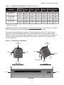
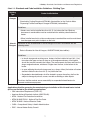
1
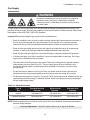
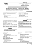
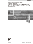
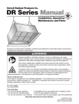
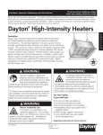
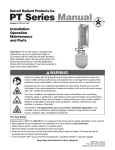
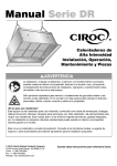
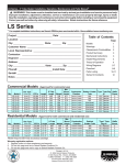
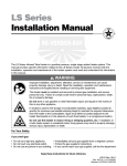
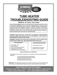
Detroit Radiant Products Co.
PH Series Manual
Installation, Operation,
Maintenance and Parts
!
All persons involved with the installation, operation and maintenance of the heater system must read and
understand the information in this manual.
!
WARNING
Improper installation, adjustment, alteration, service or maintenance can cause
property damage, injury or death. Read and understand the installation, operating
and maintenance instructions thoroughly before installing or servicing this equipment.
This heater must be installed and serviced by trained gas installation and service
personnel only. Inspect the heater annually. Failure to comply could result in personal
injury, asphyxiation, death, fire and/or property damage.
Not for indoor residential use. This heater is not approved for use in any indoor
residential application. This includes, but is not limited to, attached garages, solarium,
living quarters, etc. Installation in residential indoor spaces may result in property
damage, asphyxiation, serious injury or death.
Storage of gasoline and other flammable vapors and liquids in the vicinity of this or
any other appliance may result in fire or explosion. Do not store or use gasoline or
other flammable vapors and liquids in the vicinity of this or any other appliance.
Maintain clearance to combustibles.
For Your Safety
If you smell gas:
• Shut off gas to the appliance. • Extinguish any open flame. • Do not try to light any appliance.
• Do not touch any electrical switch. • Call your gas supplier. Do not use any phone in your building.
• Follow the gas supplier’s instructions.
• If you cannot reach your gas supplier, call the fire department.
Keep these instructions for future reference.
LIOPH-Rev. 29110
Print: LIOPH-3M-10/10.r1.10-3-11 (CDS)
Replaces: LIOPH-3M-12/08
Contents
1.0 Safety . . . . . . . . . . . . . . . . . . . . . . . . . . . . . . . . . . . . . . . . . . . . . . . . . . . . . . . . . . . . . . . . . . . . 3
Warning Symbols . . . . . . . . . . . . . . . . . . . . . . . . . . . . . . . . . . . . . . . . . . . . . . . . . . . . . 3
Applications . . . . . . . . . . . . . . . . . . . . . . . . . . . . . . . . . . . . . . . . . . . . . . . . . . . . . . . . . . 3
Clearance to Combustibles . . . . . . . . . . . . . . . . . . . . . . . . . . . . . . . . . . . . . . . . . . . . . . 4
Gas Connection . . . . . . . . . . . . . . . . . . . . . . . . . . . . . . . . . . . . . . . . . . . . . . . . . . . . . . . 6
Standards, Certifications and Government Regulations . . . . . . . . . . . . . . . . . . . . . . . . 6
Safety Signs and Labels . . . . . . . . . . . . . . . . . . . . . . . . . . . . . . . . . . . . . . . . . . . . . . . . . 8
2.0 Installation . . . . . . . . . . . . . . . . . . . . . . . . . . . . . . . . . . . . . . . . . . . . . . . . . . . . . . . . . . . . . . . 9
Design . . . . . . . . . . . . . . . . . . . . . . . . . . . . . . . . . . . . . . . . . . . . . . . . . . . . . . . . . . . . . 9
Heater Mounting . . . . . . . . . . . . . . . . . . . . . . . . . . . . . . . . . . . . . . . . . . . . . . . . . . . . . . 11
Gas Supply . . . . . . . . . . . . . . . . . . . . . . . . . . . . . . . . . . . . . . . . . . . . . . . . . . . . . . . . . . 13
Electrical Requirements . . . . . . . . . . . . . . . . . . . . . . . . . . . . . . . . . . . . . . . . . . . . . . . . 16
Ventilation . . . . . . . . . . . . . . . . . . . . . . . . . . . . . . . . . . . . . . . . . . . . . . . . . . . . . . . . . . . 17
3.0 Operation . . . . . . . . . . . . . . . . . . . . . . . . . . . . . . . . . . . . . . . . . . . . . . . . . . . . . . . . . . . . . . . . . 18
Sequence of Operation . . . . . . . . . . . . . . . . . . . . . . . . . . . . . . . . . . . . . . . . . . . . . . . . . 18
Wiring Diagrams . . . . . . . . . . . . . . . . . . . . . . . . . . . . . . . . . . . . . . . . . . . . . . . . . . . . . . 19
4.0 Maintenance . . . . . . . . . . . . . . . . . . . . . . . . . . . . . . . . . . . . . . . . . . . . . . . . . . . . . . . . . . . . . . 20
Periodic Maintenance . . . . . . . . . . . . . . . . . . . . . . . . . . . . . . . . . . . . . . . . . . . . . . . . . . 20
Troubleshooting Guide . . . . . . . . . . . . . . . . . . . . . . . . . . . . . . . . . . . . . . . . . . . . . . . . . 21
5.0Parts . . . . . . . . . . . . . . . . . . . . . . . . . . . . . . . . . . . . . . . . . . . . . . . . . . . . . . . . . . . . . . . . . . . . 22
6.0Limited Warranty . . . . . . . . . . . . . . . . . . . . . . . . . . . . . . . . . . . . . . . . . . . . . . . . . . . . . . . . . . 24
2
1.0 Safety • Warning Symbols • Applications
1.0 Safety
!
!
WARNING
Improper installation, adjustment, alteration, service or maintenance can cause
property damage, serious injury or death. Read and understand, the installation,
operating and maintenance instructions thoroughly before installing or servicing this
equipment. Only trained, qualified gas installation and service personnel may install or
service this equipment.
Warning Symbols
Safety is the most important consideration during installation, operation and maintenance of the infrared
heater. You will see the following symbols and signal words when there is a hazard related to safety or
property damage.
!
!
WARNING
Warning indicates a potentially hazardous situation
which, if not avoided, could result in death or injury.
CAUTION
Caution indicates a potentially hazardous situation
which, if not avoided, could result in minor or
moderate injury.
NOTICE
Notice indicates a potentially hazardous situation
which, if not avoided, could result in property
damage.
Applications
This is not an explosion proof heater. Consult your local Fire Marshall, insurance carrier and other
authorities for approval of the proposed installation.
Commercial / Industrial
Infrared heaters are designed and certified for use in industrial and commercial buildings such as outdoor
!
restaurant patios, warehouses, manufacturing plants, aircraft hangars and vehicle maintenance shops.
For maximum safety, the building must be evaluated for potential hazards before installing the heater
system. A critical safety factor to consider before installation is the clearance to combustibles.
Outdoor Residential
This heater may only be used in outdoor residential applications and is NOT approved for use in any
indoor residential application. This includes, but not limited to, attached garages, living quarters, solarium,
etc. Consult the local fire marshal and/or insurance provider if unsure of your application.
!
WARNING
Not For Indoor Residential Use. Installation of a infrared heater system in
residential indoor spaces may result in property damage, serious injury or
death. In residential applications this heater may only be used outdoors.
3
1.0 Safety • Clearance to Combustibles
Clearance to Combustibles
!
WARNING
Improperly connected gas lines may result in serious injury or death, explosion,
poisonous fumes, toxic gases, asphyxiation. Connect gas lines in accordance to national,
state, provincial and local codes.
Placement of explosive objects, flammable objects, liquids and vapors close to the heater
may result in explosion, fire, property damage, serious injury or death. Do not store, or
use, explosive objects, liquids and vapor in the vicinity of the heater.
Failure to comply with the published clearances to combustibles could result in personal
injury, death and/or property damage.
In locations used for the storage of combustible materials, signs must be posted to
specify the maximum permissible stacking height to maintain the required clearances
from the heater to the combustibles. Signs must either be posted adjacent to the heater
thermostats or in the absence of such thermostats, in a conspicuous location.
Hazards Include:
For maximum safety the building must be evaluated for hazards before installing the heater system.
Examples include, but not limited to:
•
•
•
•
•
•
•
Gas and electrical lines
Combustible and explosive materials
Chemical storage areas
Areas of high chemical fume concentrations
Provisions for accessibility to the heater
Adequate clearances around air openings
Combustion and ventilating air supply
•
•
•
•
•
•
•
Vehicle parking areas
Vehicles with lifts or cranes
Storage areas with stacked materials
Lights
Sprinkler heads
Overhead doors and tracks
Dirty, contaminated environment
A critical safety factor to consider before installation is the clearances to combustibles. Clearance to
combustibles is defined as the minimum distance you must have between the infrared heater and the
combustible item. Considerations must also be made for moving objects around the infrared heater. The
following is a partial list of items to maintain clearances from:
Combustible items: Moving Objects:
•
•
•
•
•
•
•
•
•
•
Wood
Paper
Fabric
Chemicals
Wall or roof insulation
Overhead doors
Vehicle lifts
Cranes
Hoists
Car wash equipment
When installing the infrared heater system, the minimum clearances to combustibles must be maintained.
These distances are shown in Chart 1.1 and on the minimum clearance to combustibles label
(F/N: LLPCL002) found on the heater. If you are unsure of the potential hazards, consult your local fire
marshall, fire insurance carrier or other qualified authorities on the installation of gas fired infrared heaters
for approval of the proposed installation.
4
1.0 Safety • Clearance to Combustibles
Chart 1.1 • Clearance to Combustibles in Inches (see Figure 1.1)
Model No.
PH 28 (-SS)
28,000 [N,P]
PH 31 (-SS)
31,000 [N,P]
PH 34 (-SS)
34,000 [N,P]
Mounting
Angle*
Sides
Back
Top
Below
End(s)
Front
0°
14
N/A
13
46
22
N/A
30°
N/A
8
17
46
22
46
0°
14
N/A
13
46
22
N/A
30°
N/A
8
17
46
22
46
0°
14
N/A
13
46
22
N/A
30°
N/A
8
17
46
22
46
* Heaters mounted on an angle between 0° to 30° must maintain clearances posted for 0° or 30°; whichever is greater.
Important! If the heater is mounted beneath a non-combustible surface an 8 in. minimum top clearance
must be maintained from the top of the heater to prevent overheating the controls.
Clearance to combustible distances represent a surface temperature of 90°F (32°C) above ambient
temperature. Ensure that building materials with a low heat tolerance (i.e, awnings, fabrics, plastics,
sprinklers, insulation) are protected against degradation. This may require the heater to be mounted at a
distance in excess of the published clearances to combustibles. Contact the factory or the building
material manufacturer.
Figure 1.1 • Clearance to Combustibles
Top
(to ceiling)
Side
Top
(to ceiling)
Back
Side
Front
30˚
Inlet side down
Below
Below
END VIEW
0° MOUNTING ANGLE
END VIEW
30° MOUNTING ANGLE
End
End
SIDE VIEW
5
1.0 Safety • Gas Connection • Standards, Certifications and Government Regulations
Gas Connection
!
WARNING
An approved connector, suitable for the environment of equipment usage, is required. Visible or
excessive swaying, flexing and vibration of the gas connections must be avoided to prevent failure.
Neither the gas pipe nor the connector shall be placed in the flue discharge area or in direct contact
with infrared rays. In no case shall the gas supply support or bear weight of the heater.
To ensure your safety, and comply with the terms of the warranty, all units must be installed in accordance
with these instructions.
Standards, Certifications and Government Regulations
Installation of this infrared heater must comply with all applicable local, state and national specifications,
regulations and building codes. Contact the local building inspector and/or fire marshall for guidance.
In the absence of local codes, the installation must conform to the latest edition of the National Fuel Gas
Code, ANSI Z223.1 (NFPA 54).
Chart 1.2 • Standards and Code Installation Guidelines • Building Aspect
Building
Aspect
Electrical
Codes And Guidelines
The heater must be electrically grounded in accordance with the following codes:
Refer to National Electrical Code®, ANSI/NFPA 70 (latest edition). Wiring must conform to
the latest edition of National Electrical Code®, local ordinances, and any special diagrams
furnished.
Venting
Unvented heater must meet ventilation requirements. See page 17.
6
1.0 Safety • Standards, Certifications and Government Regulations
Chart 1.3 • Standards and Code Installation Guidelines • Building Type
Building
Type
Public
Garages
Codes And Guidelines
Installation of this infrared heater in public garages must conform to the following codes:
Standard for Parking Structures NFPA 88A (latest edition) or the Code for Motor
Dispensing Facilities and Repair Garages NFPA 30A (latest edition).
Guidelines:
• Heaters must not be installed less than 8 ft. (2.4 m) above the floor. Minimum clearances to combustibles must be maintained from vehicles parked below the
heater.
• When installed over hoists, minimum clearances to combustibles must be maintained from the upper most point of objects on the hoist.
Aircraft
Hangars
Installation of this infrared heater in aircraft hangars must be in accordance with the
following codes:
Refer to Standard for Aircraft Hangars, ANSI/NFPA 409 (latest edition).
Guidelines:
• In aircraft storage and servicing areas, heaters shall be installed at least 10 ft. (3 m) from above the upper surface of wings or of the engine enclosures of the highest aircraft that may be housed in the hangar. The measurement shall be made from the wing or engine enclosure, whichever is higher from the floor, to the bottom of the
heater.
• In areas adjoining the aircraft storage area (e.g., shops, offices) the bottom of heaters shall be installed no less than 8 ft. (2.4 m) above the floor.
• Suspended or elevated heaters shall be located in spaces where they shall not be subject to damage by aircraft, cranes, movable scaffolding or other objects.
Provisions shall be made to assure accessibility to suspended infrared heaters for
recurrent maintenance purposes.
Applicable authorities governing the manufacturing or installation of this infrared heater include
(but are not limited to) the following organizations:
• CSA International Requirement (CSA 2.37).
• American National Standards Institute (ANSI Z83.26).
• NFPA - National Fire Protection Association.
• NFPA 54/ANSI Z223.1 - National Fuel Gas Code.
• NFPA 70/ANSI - National Electrical Code.
• OHSA - Occupational Safety & Health Administration.
• IRSC - Infrared Heater Safety Council.
7
1.0 Safety • Safety Signs and Labels
Safety Signs and Labels
It is important to provide warnings to alert individuals to potential hazards and safety actions. ANSI
Z83.26/CSA 2.37 require you to post a sign “specifying the maximum permissible stacking height to
maintain the required clearances from the heater to the combustibles” near the heaters thermostat or in
absence of such thermostats in a conspicuous location.
Safety warning labels must be maintained on the infrared heater. Illustrations of the safety labels, and their
locations, are pictured below. In locations used for the storage of combustible materials, signs must be
posted to specify the maximum permissible stacking height to maintain the required clearances from the
heater to combustibles. Signs must either be posted adjacent to the heater thermostats or in the absence
of such thermostats in a prominent location.
DETROIT RADIANT INFRA-RED RADIANT HEATER
FOR OUTDOOR & INDOOR (Non-Residential) INSTALLATION ONLY.
High Intensity Infrared Heater
Class IIIA Permanent Label
MODEL NO.
PH-34N
Volts AC:
120V - 60Hz
AMPS - Starting:
0.25
AMPS - Running:
0.24
INPUT BTU/H
34,000
Control Voltage
120V - 60Hz
AM
Manifold Pressure:
P
5.0 INCHES W.C.
S
Minimum Inlet Pressure:
14.0 INCHES W.C.
LE
FOR USE WITH
Natural Gas
Heater Type
6.0 INCHES W.C.
Minimum Mounting Angle:
0
DEGREES
Maximum Mounting Angle:
30 DEGREES
DESIGN COMPLIES WITH:
ANSI Z83.19a-2002-Gas Fired High Intensity Infra-Red Heater
WARNING
DO NOT
ROTATE CONTROL
ASSEMBLY
USE TWO
WRENCHES
TO TIGHTEN
OBSERVE
PROPER GAS
FOR
GAS TYPE
ONLY
DETROIT RADIANT PRODUCTS COMPANY
21400 HOOVER ROAD - WARREN, MI
(586) 756-0950
www.detroitradiant.com
CSA 5.90 (5th Ed.) Gas Fired Infra-Red Patio Heater
Serial No.: 0812XXXXXXXXXX 0001
Rating Label
F/N: LL02 - Observe Proper Gas Type (Natural Gas)
F/N: LL03 - Observe Proper Gas Type (LP Gas)
Top Panel
F/N: LL01 - Clearance Safety Tag
(Affix adjacent to heater’s thermostat).
F/N: LLPCL002
Patio Heater Clearance
to Combustibles Label
8
2.0 Installation • Design
2.0 Installation
WARNING
!
Read and understand, the installation, operating and maintenance instructions
thoroughly before installing or servicing this equipment.
Only trained, qualified gas installation and service personnel may install or service
this equipment.
!
NOTICE
CAUTION
Radiant heat is capable of damaging or destroying
certain materials or items. Do not store material or
items underneath the heater. Always maintain
clearance to combustibles.
This heater cannot be used in a building with a
roof that is not insulated or where condensation
problems can occur.
Design
To ensure a safe, properly designed heating system, a layout should be developed for the correct
placement of the infrared heater(s). Aside from safety factors such as clearance to combustibles (see
Chart 1.1 on page 5), you should take into consideration:
• The environment (e.g., is it cold/drafty, average, protected)?
NOTE:The effective infrared surface temperature of a person or object may
be diminished with wind above 5 mph, wind barriers may be required.
•
•
•
•
•
•
•
•
What is the area of heat coverage (e.g., sq. ft.) needed (Chart 2.1, Figure 2.2)?
Is the heater being used in a social gathering area, or work station(s)?
The mounting height of the heater (Chart 2.1, Figure 2.2).
The type of mounting to be used.
Physical space needed for the heater (Figure 2.1).
Gas supply and connections.
Combustion, ventilating air supply and exhaust path.
Electricity and wiring to the heater.
Fire sprinkler heads must be located at an appropriate distance from the heater to avoid an inadvertent
discharge. This distance may exceed the published clearance to combustibles. Certain applications may
require the use of high temperature sprinkler heads or relocation of the heaters.
!
CAUTION
Fire sprinkler systems containing propylene glycol, antifreeze or other potentially flammable substances
shall not be used in conjunction with this heater without careful consideration for and avoidance of
inadvertent discharge hazards. For further information consult NFPA 13. Always observe applicable state
and local codes.
9
2.0 Installation • Design
Figure 2.1 • Heater Dimensions
5.5”
3.25”
8.5”
45”
9”
SIDE VIEW
END VIEW
Chart 2.1 • Recommended Mounting Heights
Model & Input
PH-28
28,000
BTU/H
PH-31
31,000
BTU/H
PH-34
34,000
BTU/H
Recommended
Mounting Height
(Dim. A)
Approximate
Coverage Area
Approx. Coverage
(sq. ft.)
8’-0” to 8’-6”
7’ x 7’
49 sq. ft.
8’-0” to 9’-0”
8’ x 8’
64 sq. ft.
8’-6” to 10’-0”
9’ x 9’
81 sq. ft.
NOTE: This chart is provided as a guideline. Actual conditions dictate variances from this data.
Figure 2.2 • Recommended Mounting Heights
A
10
2.0 Installation • Heater Mounting
Heater Mounting
!
WARNING
Improper suspension of the infrared heater may result in collapse and persons being
crushed. Always suspend from a permanent part of the building structure that can support
the total force and weight of the heater.
Failure to maintain minimum clearance to combustibles may result in fire and/or explosion,
property damage, serious injury or death. Always maintain minimum clearances and post
signs or provided tags (F/N: LL01) where needed. Signs should state the hazards for the
particular application and be legible for the building occupants. Consult the factory or a
factory representative for additional information on signage compliance.
The heater can be suspended with chains or rigid threaded rod. Local codes, or conditions such as wind
drafts or other variables can cause movement of the heater and may require rigid threaded rod. Avoid
excessive movement and/or vibration of the gas connection by rigidly mounting the heater (see Figure 2.4).
The Detroit Radiant optional patio heater mounting brackets (P/N: PH-BKT) can be used in place of rigid
threaded rods. Consult all applicable codes before installation.
The heater must be level from side to side and can be set at an angle between 0° and 30° from horizontal.
The gas connection and power cord must be located on the lower side (see Figure 2.3).
Figure 2.3 • Heater Orientation
Optional mounting
bracket (P/N: PH-BKT)
30°
End
End
Level end to end
When mounting the heater on an angle (0-30°), the
gas inlet and power cord must be located towards the
lower side of the heater (towards the floor).
11
2.0 Installation • Heater Mounting
Figure 2.4 shows different types of mounting configurations. Depending on the type of mounting you use,
be sure to:
1 Prepare mounting surface. If necessary, weld blocks to mounting structure, drill holes, etc.
2 Fasten beam clamp, screw hook or other type of suspension anchor to hanging point.
3 Attach and close S-Hook (P/N: S-HOOK) and #1 double-loop chain (P/N: THCS includes a 5 ft. chain
and 2 S-hooks, 4 required) to anchor. Check that it is securely attached.
4 Attach heater to chains. Adjust chain lengths until the heater is level and equal weight distribution is
achieved. Chains must be straight up and down, do not install chains at an angle.
Figure 2.4 • Heater Mounting
I-Beam
Concrete Beam
Wood Beam
Steel C-clamp
Screw Hook
Bar Joist Clip
S-Hook and
#1 double-loop
chain (recommended)
Rigid threaded rod
and turnbuckle
(field supplied)
0-30°
0-30°
0-30°
Optional mounting
bracket (PH-BKT)
attached to ceiling.
Optional mounting
bracket (PH-BKT)
attached to wall.
0-30°
30° Mounting Angle
0-30°
0° Mounting Angle
30° Mounting Angle
0° Mounting Angle
12
2.0 Installation • Gas Supply
Gas Supply
!
WARNING
Improperly connected gas lines may result in fire, explosion,
poisonous fumes, toxic gases, asphyxiation and death.
Connect gas lines in accordance to national, state, provincial
and local codes.
The gas supply to the infrared heater must be connected and tested in accordance with national, state,
provincial and local codes along with the guidelines in the Detroit Radiant PH Series manual. Refer to the
latest edition of the ANSI Z223.1 (NFPA 54) Standard.
Important! Before connecting the gas supply to the infrared heater(s):
• Check for conditions such as drafts or other variables which might cause excessive movement of the unit and cause damage to the gas connection. Ensure that the unit is securely mounted and connect the gas with an approved connection device suitable for the environment of use.
• Check that the gas piping and service has the capacity to handle the load of all heaters being installed, as well as any other gas appliances being connected to the supply line.
• Check that the main gas supply line is of proper diameter to supply the required fuel pressures.
• If utilizing used pipe, verify that its condition is clean and comparable to a new pipe. Test all gas supply lines in accordance with local codes.
• Test and confirm that inlet pressures are correct. Refer to the rating plate for required minimum and maximum pressures (see Chart 2.2). The gas supply pipe must be of sufficient size to provide the required capacity and inlet pressure to the heater (if necessary, consult the local
gas company).
• For test pressures in excess of 1/2 psig (3.5 kPa), the heater and ball shutoff valve must be disconnected from the gas supply piping system during any pressure testing of the system.
• For test pressures equal to or less than 1/2 psig (3.5 kPa), the heater must be isolated from the gas supply piping system by closing it’s individual manual shutoff valve during any pressure testing of the gas supply piping system.
Chart 2.2 • Manifold Pressure
Type of
Gas
Required Manifold Pressure
Minimum Inlet
Pressure
Maximum Inlet
Pressure
Natural
5.0 inches W.C.
6.0 inches W.C.
14.0 inches W.C.
Liquefied Petroleum
10.0 inches W.C.
11.0 inches W.C.
14.0 inches W.C.
NOTE:Check manifold pressure at the tap on the ball shutoff valve. Readings will be above atmospheric pressure during operation.
Pressure Equivalents: 1 inch W.C. equals .058 oz./sq. in. equals 2.49 Mbar.
13
2.0 Installation • Gas Supply
To connect the gas:
WARNING
!
Failure to install, operate or service this appliance in the approved manner may result in
property damage, injury or death. This heater must be installed and serviced by trained
gas installations and service personnel only.
The installation of this heater must conform with local building codes or, in the absence
of such codes, the National Fuel Code (NFPA 54).
The gas outlet must be in the same room as the appliance and accessible. It may not be concealed within
or run through any wall, floor or partition.
1
Install a sediment trap / drip leg if condensation may occur at any point of the gas supply line. This will decrease the possibly of loose scale or dirt in the supply line entering the heater’s control system and causing a malfunction. NOTE: High pressure gas above 14.0 inches W.C. (water column pressure) requires a high pressure regulator and ball valve (field supplied).
2 A stainless steel flexible hose (PH-FC24) formed into a smooth C-shape is recommended (Figure 2.5). If local codes prohibit the use of a gas hose, then a swing joint may be used.
3 Attach the ball valve to the gas supply pipe. Apply pipe compound to NPT adapter threads to seal the joint. Use only a pipe compound resistant to liquid petroleum.
NOTE: Provide a 1/8 in. NPT plugged tapping accessible for test gauge connection immediately upstream of gas connection to the heater (provided on ball valve, when supplied).
4 Attach a gas connector (PH-FC24) to the adapter and the heater’s gas inlet. Seal the joints.
!
Important! The fittings (nuts) on the flexible connector (optional PH-FC24) must be connected to an adapter. They may not be directly connected to the gas supply pipe.
Excessive torque on the manifold may misalign the orifice. Always use two wrenches to tighten mating pipe connections.
5 Final assembly must be tested for gas leaks according to NFPA or local codes.
!
WARNING
Testing for gas leaks with an open flame or other sources of ignition may lead to a fire or explosion and cause serious injury or death. Test in accordance with NFPA or local codes.
To disconnect the gas:
1 Disconnect the power to the heater.
2 Turn off the gas supply to the heater and “bleed” the gas line.
3 Using two wrenches, slowly loosen the fittings. Excessive torque on the manifold may misalign the orifice.
4 Inspect the hose and fittings for abrasion, wear or damage. Replace if necessary.
14
2.0 Installation • Gas Supply
!
!
WARNING
Failure to disconnect the electricity to the heater before disconnecting the gas supply
may result in explosion, fire, property damage, injury or death.
!
WARNING
Conditions such as wind drafts or other variables can cause movement of the heater and
may require it to be rigidly mounted. Avoid excessive movement and/or vibration of the
gas connection by rigidly mounting the heater.
Figure 2.5 • Gas Connection (shown installed with a flexible hose)
NOTE: Do not exceed 14 inches W.C. to the appliance.
Use a regulator when gas supply pressure exceeds 14 inches W.C.
Regulator
(field supplied
when required)
Shut off valve /
inlet tap
Elbows
(field supplied)
Stainless steel gas connector
(P/N: PH-FC24), formed into
smooth C-shape.
Shut off valve /
inlet tap
Optional
mounting
bracket
(P/N: PH-BKT)
Stainless steel gas connector
(P/N: PH-FC24), formed into
smooth C-shape.
Drip leg / Sediment trap
(field supplied)
15
2.0 Installation • Electrical Requirements
Electrical Requirements
!
WARNING
Incorrect or improper wiring may result in shock, injury or death. Field wiring to the heater
must be connected and grounded in accordance with national, state, provincial, local
codes and to the guidelines in this manual. Refer to the most current revisions to the
ANSI/NFPA 70 Standard.
NOTICE
Radiant heat may damage the flexible power cord. Always keep the flexible power cord away from the
heater. Do not allow the power cord to be subjected to radiant heat.
Control systems are initiated by either 120VAC or optional 24VAC control voltage. A 120VAC system
can be operated directly with 120VAC to the heater. Heaters with the optional relay can be controlled with
24VAC transformers (sold separately) must be used to supply power of sufficient VA rating for single or
multiple connected installations.
Important! Proper grounding and polarity are essential. If the system is not properly grounded, it cannot
determine the presence of a flame and will lockout and shut off.
For wiring of controls see Figure 2.7 below. It is recommended that the control be installed on the hot
side of a fused supply line and have a sufficient ampere capacity rating for the heater(s) it will control
(see Figures 3.1 & 3.2).
Figure 2.7 • Typical Field Wiring
PH Series 120 VAC with 24 VAC Control (PH-24VAO)
PH Series 120 VAC
Optional
mounting bracket
(P/N: PH-BKT)
Optional mounting
bracket
(P/N: PH-BKT)
PH Series
Heater
120VAC black
power cord
120VAC black
power cord
24VAC yellow
control cord
120VAC thermostat,
timer or switch
(field supplied)
24VAC thermostat,
timer or switch
(field supplied)
Transformer
Hot
Hot
120VAC
Neutral
Neutral
16
24VAC
PH Series
Heater
2.0 Installation • Ventilation
Ventilation
!
WARNING
Improper or insufficient ventilation may result in explosion, fire, health
problems, carbon monoxide poisoning or death. Vent enclosed spaces and
buildings according to national, state, provincial and local codes.
This infrared heater must be vented in accordance with national, state, provincial and local codes and
the guidelines in the Detroit Radiant PH Series manual. Refer to the latest edition of the ANSI Z223.1
(NFPA 54) Standard.
It is required that the upper levels of the space to be heated are properly ventilated to supply combustion
air to the heaters and to sufficiently dilute the products of combustion. It is also important to keep the flue
discharge area clear of gas piping and electrical wiring (see Figure 2.6).
Provisions must also be made to provide sufficient fresh air intake area and exhaust air outlet area. Natural
or mechanical means shall be provided to supply and exhaust at least 4 CFM/1000 BTU/h of total gas input
of heaters installed. Exhaust openings for the removal of flue products must be above the level of the
heater(s).
Where insufficient air movement exists, induced air displacement is required. A balanced system is
essential to avoid negative building pressure which causes excessive infiltration, unfavorable drafts and
affects combustion efficiency.
Air displacement may be accomplished by either gravity or mechanical means. Mechanical exhausters are
preferred and typically mounted at high points on the roof over where stagnant air accumulates inside. For
a flat roof, considerations of prevailing winds, high and low pressure areas, and distribution of air movement
must be taken into consideration when locating exhausters.
Best air distribution is accomplished by using a number of small exhausters versus one large exhauster.
Provide a minimum of one square inch of inlet area per 1000 BTU/h for combustion air supply. Inlet opening
in the building should be well distributed, located high on the wall and should direct incoming air upward to
dilute products of combustion while preventing drafts at lower levels. Inlets are typically 1 to 3 sq. ft.
In certain applications, local codes may require that mechanical exhaust systems be interlocked with the
heaters to enable both to function simultaneously or allow control of exhausters with a ceiling mounted
humidistat.
Figure 2.6 • Hot Flue Discharge
Discharge released from side
air channels. Keep area clear of
gas piping and electrical wiring.
17
3.0 Operation • Sequence of Operation
3.0 Operation
!
WARNING
Improper operation of the heater may result in explosion, fire, shock and
carbon monoxide poisoning. Follow all guidelines and warnings in this manual
and national, state, provincial and local codes. Always conduct safety checks
before operating the heater. Do not operate the heater in unsafe conditions.
Important! Before operating the heater, conduct the following safety procedures:
• Check for any possible gas leaks.
• Alert all persons about the hazards of high surface temperature and to keep a safe distance away in order to avoid burns and possible clothing ignition.
• Provide supervision when young children are in the area of the heater.
• Check to make sure clothing isn’t hung from the heater and that flammable materials are not placed on or near the heater.
• Check that all guards or protective devices are in place and secure.
• Check the hose assembly for excessive abrasion, wear or damage. If necessary replace.
The replacement hose must be that specified by Detroit Radiant Products.
• Check control compartment, burners and circulating air passages for debris. If necessary, clean the debris.
Sequence of Operation:
Starting Circuit:
When voltage is applied to L1 and L2, a circuit is completed from L1 via the blower motor to L2. The
blower fan is mounted in the control box and rated to supply sufficient air for combustion. Air pressure
generated by the blower will cause the normally open pressure switch to close. Another circuit is
completed from L1 to the spark ignition module and back to L2. After a seven (7) second pre-purge, the
spark electrode and gas valve are energized simultaneously. The trial for ignition is fifteen seconds.
Running Circuit:
After ignition, the flame rod monitors the flame. As long as a flame is present, the valve is held open. If the
flame is lost, the control acts to close the valve within one second, and a new trial sequence identical to
that at start-up is initiated. If proof of flame is not established within the 15 second trial for ignition, the unit
will retry two additional times before entering lockout mode. If lockout occurs, the control can be reset by
briefly interrupting the power source.
18
3.0 Operation • Wiring Diagrams
Lighting Instructions:
1 Rotate heater’s valve knob to ON position.
2 Close electrical circuit (usually thermostat).
3 If the heater fails to light, turn OFF gas, open electrical circuit and wait 5 minutes before repeating.
Shutdown Instructions:
1 Open electrical circuit (usually thermostat).
2 Turn off electrical power if service is to be performed.
3 Rotate heater’s valve knob to OFF position.
Wiring Diagrams
Figure 3.1 • PH Series 120VAC
Figure 3.2 • PH Series 120VAC with 24VAC Control
Amp draw:
120VAC - .25 starting, .24 running
Amp draw:
24VAC - .10 starting.
120VAC - .25 starting, .24 running.
L1 (120VAC)
L1 (120VAC)
NEUTRAL
NEUTRAL
DOOR SWITCH
DOOR SWITCH
24V
(FIELD SUPPLIED
BK
THERMAL FUSE
BK
THERMAL FUSE
W
BK
N.O. RELAY
BK
BLOWER
MOTOR
BK
BLOWER
MOTOR
BK
BK
BK
BK
PRESSURE
SWITCH
DSI MODULE
(120VAC)
DSI MODULE
(120VAC)
HIGH VOLTAGE
HIGH VOLTAGE
O
BK
THERMOSTAT
NEUTRAL
VALVE
GROUND
SENSE
NEUTRAL
W
SENSE
NEUTRAL
O
BK
G
W
G
W
W
W
BK
BK
W
BK
W
BK
G
G
BK
W
BK
W
ELECTRODE
ASSEMBLY
W
THERMOSTAT
NEUTRAL
VALVE
GROUND
PRESSURE
SWITCH
ELECTRODE
ASSEMBLY
GAS VALVE
19
GAS VALVE
4.0 Maintenance
4.0 Maintenance
!
WARNING
Always wear clothing that protects the body and use protective glasses when
maintaining the heater.
Electrical shock or explosion may occur when conducting maintenance while
the heater is connected to the power source and gas supply. Disconnect
power and gas supply to heater before servicing.
Burner malfunction may result in explosion or fire. Never operate the heater if
there are any signs of malfunction, excessive wear or damage. Call a
professional for assistance.
NOTICE
Cleaning the heater elements with high pressure air may cause damage to the elements and equipment
failure. Do not blow out heating elements with high pressure air.
Before each use:
• Check the gas supply line and hose assembly for any possible leaks or damage.
• Check heater elements for debris. Visually check burner flames.
• Keep the heated area clear and free of combustible materials, gasoline and flammable vapors and liquids. Ensure there is no obstruction of the flow of combustion and ventilation.
Periodic maintenance:
• Clean the heater with cleaning agents suitable for the unit’s construction material (i.e., stainless steel cleaner).
• Lubricate moving parts.
• Inspect the gas supply piping system for signs of corrosion or failure. Replace if necessary.
Before conducting maintenance on the heater disconnect the power and gas supply. When pressure
testing the gas supply piping system follow these guidelines:
• At a test pressure in excess of 1/2 psig (3.5 kPa) the heater and ball shutoff valve must be disconnected from the gas supply piping system during any pressure testing of the system.
• At a test pressure equal to or less than 1/2 psig (3.5 kPa) the heater must be isolated from the
gas supply piping system by closing it’s individual manual shutoff valve during any pressure testing of the gas supply piping system.
Cleaning the main burner:
1 Gently use an air hose to blow any accumulated dust and/or dirt off the heater. Air hose pressure should not exceed 30 psig.
2 Gently, pass the air hose over the entire exposed area of the ceramic. A distance of 2’ to 4’ from the unit is recommended.
3 Gently place the air hose outlet into the venturi tube and allow the air to flow for approximately one minute.
During long periods of non-usage, remove or cover heater with a polyethylene bag and shut off gas
supply. If further service to the heater is desired, contact your representative or the factory.
20
4.0 Maintenance • Troubleshooting Guide
Chart 4.1 • Troubleshooting Guide
Symptom
Possible Cause
Corrective Action
Burning of gas-air mixture inside • Heater mounted at incorrect angle.
plenum (flashback).
• Excessive drafts.
• Gas leaking at orifice.
• Separation of ceramic grids.
• Ceramic grids cracked.
• Mount at a 0˚- 30˚angle from horizontal.
• Relocate heater or shield from draft.
• Check with leak detector solution.
• Replace burner.
• Replace burner.
Delayed ignition.
• Electrode out of specification.
• Low gas pressure.
• Partially blocked orifice.
• Improper orifice size.
• Incorrect gas.
• See ignition system insert.
• See Section 2.0, Gas Supply.
• Clean or replace gas orifice.
• Consult distributor.
• See unit rating plate.
Low ceramic surface
temperature or excessive
rollout.
• Dirty or plugged burner ceramics.
• Partially blocked orifice.
• Low inlet gas pressure.
• High or low manifold gas pressure.
• Foreign matter in venturi tube.
• Excessive dark spots on burner.
• Gas supply piping too small.
• Incorrect gas.
• See periodic maintenance instructions.
• Remove and clean.
• See Section 2.0, Gas Supply.
• Adjust main valve regulator as specified.
• See periodic maintenance instructions.
• See periodic maintenance instructions.
• Increase inlet pressure or replace piping.
• See unit nameplate.
Control system overheating.
• Heater not mounted correctly.
• Heater mounted too close to
ceiling.
• Mounting angle 0°- 30°. Level left to right.
• Observe clearance to combustibles.
Gas odor.
• Loose pipe connection.
• Check connections. Tighten as necessary.
Heater cycles repeatedly.
• Heater located in drafty area.
• Low gas pressure.
• Thermostat located in drafty area.
• Defective flame electrode or circuit
board.
• Relocate or shield from draft.
• See Section 2.0, Gas Supply.
• Relocate thermostat.
• Replace electrode and/or circuit board.
No spark; no ignition.
• Lack of 120V or 24V incoming
voltage.
• Open high voltage wire.
• Fan not operating.
• Check power supply.
• Improper electrode gap.
• Loose or open wire connection.
• Pressure switch not satisfied.
• Poor or no equipment ground.
• Unit in “safety lockout” mode.
• Defective control module.
Heater lights, and “locks out”
after approximately 10 seconds.
• Poor or no equipment ground.
Spark is present. No main gas
operation. Unit “locks out”.
• Gas valve in “OFF” position.
• Defective gas valve.
Heater will not shut off.
• Polarity is reversed.
• Low gas pressure.
• Electrode not sensing.
• Heater mounted at incorrect angle.
• Defective control module.
• Isolate an ohm for resistance, replace if 0.
• Locate source of electrical problem or
replace faulty fan.
• See Ignition System specifications.
• Check all wires, tighten or replace.
• Verify fan operation. Remove obstructions.
• Check all connections, provide positive
earth ground.
• Interrupt power source, repeat trial
for ignition.
• Replace circuit board.
• Check all connections, provide positive
earth ground.
• 120VAC to black, neutral to white.
• See Section 2.0, Gas Supply.
• Relocate or replace if electrode is defective.
• Mounting angle 0˚- 30˚.
• Replace circuit board.
• Defective control module.
• Turn to “ON” position.
• Isolate and check for resistance, replace
if 0.
• Replace circuit board.
• Defective thermostat or wiring.
• Gas valve stuck or open.
• High gas pressure.
• Replace thermostat or repair wiring.
• Replace gas valve.
• See Section 2.0, Gas Supply.
21
5.0 Parts • Heater Components and Parts List
5.0 Parts
Figure 5.1 • Heater Components
108
174
145
143
146
148
149
133
142
147
181
171
162
116
163
140, 141
197, 297 115
137
190
134
104, 204
137
198, 298
196
193
173
156
155
152
153
199, 299
191
164
168
161
125
105, 205
190
180
121
121
158
151
192
172
144
157
194
PART#
DESCRIPTION
PART#
DESCRIPTION
PH-101
Top Panel
PH-134 Optional 24VAC Cord Set
PH-102 Left Frame (Inlet) Side Panel (120VAC)
PH-137 Strain Relief (TP-68B)
PH-102A Left Frame (Inlet) Side Panel (Opt. PH-24VAO)
PH-140 Gas Valve - Natural Gas
PH-103 Right Frame Side Panel
PH-141 Gas Valve - Propane
PH-104 Control End Panel w/ Louvers & Hinge
PH-142 3/8 in. Closed Pipe Nipple
PH-105 Service Access Door
PH-143 3/8 in. Reducer Fitting (TP-56)
PH-106 End Panel
PH-144 Gas Orifice (Specify Model)
PH-108 Valve Mounting Bracket
PH-145 9/16 in. Ext. Lock Washer
PH-110
Rain Guard
PH-146 9/16 in. - 18 Hex Jam Nut
PH-111
8 in. x 35 in. Egg Crate (PH-EC)
PH-147 3/8 in. x 5 in. Inlet Pipe Nipple
PH-112
Egg Crate Frame w/ Flashshield
PH-148 3/8 in. Ball Valve/Inlet Tap
PH-113
Egg Crate Assembly w/ Frame & Nutsert
PH-149 Rubber Inlet Grommet
PH-115
120VAC Fan
PH-150 Igniter Electrode
PH-116
Fan Mounting Panel
PH-151 Circuit Board (MARK 10DX-117)
PH-117
Air Distribution Channel
PH-152 100-900 Harness (DRWH-120)
PH-121
Weather Stripping
PH-153 Controls Mounting Panel
PH-122 3/8 in. Black Inlet Pressure Tap Grommet
PH-155 12 in. Orange High Voltage Wire w/ Boot
PH-125 Optional 24V Picker Relay
PH-156 2-Way Crimp Connector
PH-133 120VAC Cord - 6 ft.
PH-157 Thermal Switch (TP-1033)
To order replacement parts call Detroit Radiant Products at: Voice: (586) 756-0950, Fax: (586) 756-2626
or visit our website: www.detroitradiant.com/parts
22
5.0 Parts • Heater Components and Parts List
190
102, 202, 102A, 202A
178
182,282
197, 297
106, 206
110, 210
191
192
117
117
101, 201
150
110, 210
170
122
103, 203
113
183, 283
111
112
195
PART#
DESCRIPTION
PH-158 Door Switch
PH-161 Pressure Switch (TP-264B)
PH-162 Short Vinyl Hose - 3.0 in.
PH-163 Long Vinyl Hose - 2.25 in.
PH-164 Plastic 90° Vent (TP-245)
PH-168 Brass Fitting (TP-97)
PH-170 Burner Assembly w/ Hold-Downs & Footings
PH-171 Primary Air Restrictor Plate
PH-172 Valve Mounting Panel
PH-173 Service Access Door Ledge
PH-174 Burner & Electrode Mounting Panel
PH-178 Burner End Mounting Panel
PH-180 #1/4-20 x 1/2 in. Machine Bolt (DR-20MB)
PH-181 #1/4-20 Hex Nut (DR-20HN)
PH-182 #8 x 1/2 in. SLTD HW Screw (Standard)
PH-183 #8 x 1/2 in. SLTD HW Screw (Black)
PH-190 5/16 in. x 3/4 in. Hex HD Bolt
PH-191 5/16 in. Split Washer Zinc
PH-192 5/16 in. Hex Nut
PH-193 #1/4-20 Square Cagenut
NOTE: (SS) denotes parts available in stainless steel.
PART#
PH-194
PH-195
PH-196
PH-197
PH-198
PH-199
PH-201
PH-202
PH-202A
PH-203
PH-204
PH-205
PH-206
PH-210
PH-282
PH-283
PH-297
PH-298
PH-299
23
DESCRIPTION
Control Cover Thumbscrew
#5/16-18 x 1-1/2 in. Gold Nutsert Bolt
Control Cover Hinge Rod
Hanging Bracket (Black) - 2 Req.
Wall Bracket Assembly (Black) - Opt. 2 Req.
Support Channel (Black) - Opt. 2 Req.
Top Panel (SS)
Left Frame (Inlet) Side Panel (SS) - PH-24VAO
Left Frame (Inlet) Side Panel (SS)
Right Frame Side Panel (SS)
Control End Panel w/ Louvers & Hinge (SS)
Service Access Door (SS)
End Panel (SS)
Rain Guard (SS)
#8 x 1/2” SLTD HW Screw (SS)
#8 x 1/2” SLTD HW Screw (Black or Plated SS)
Hanging Bracket (SS) - 2 Req.
Wall Bracket Assembly (SS) - Opt. 2 Req.
Support Channel (SS) - Optional 2 Req.
6.0 Limited Warranty
6.0 Limited Warranty
One-Year Limited Warranty. Patio Heaters covered in this manual, are warranted by Detroit Radiant Products Company to
the original user against defects in workmanship or materials under normal use for one year after date of purchase. Any part
which is determined to be defective in material or workmanship and returned to an authorized service location, as Detroit
Radiant Products Company designates, shipping costs prepaid, will be, as the exclusive remedy, repaired or replaced at
Detroit Radiant Products Company’s option. For limited warranty claim procedures, see PROMPT DISPOSITION below. This
limited warranty gives purchasers specific legal rights which vary from jurisdiction to jurisdiction.
Additional Limited Warranty. In addition to the above mentioned one-year warranty, Detroit Radiant Products Company
warrants the original purchaser an additional four-year extension on the ceramic burner. This extension excludes electrical/
purchased components.
General Conditions. The Company will not be responsible for labor charges for the analysis of a defective condition of the
heater or for the installation of replacement parts. The warranties provided herein will not apply if the input of the heater
exceeds the rated input at time of manufacturing or if the heater in the judgment of the Company has been subjected to
misuse, excessive dust, improper conversion, negligence, accident, corrosive atmospheres, excessive thermal shock,
excessive vibration, physical damage to the heater, alterations by unauthorized service personnel, operation contrary to the
Company’s instructions or if the serial number has been altered, defaced, or removed. The Company shall not be liable for
any default or delay in the performance of these warranties caused by contingency beyond its control, including war,
government restriction or restraints, strikes, fire, flood, short or reduced supply of raw materials, or parts.
Limitation of Liability. To the extent allowable under applicable law, Detroit Radiant Products Company’s liability for
consequential and incidental damages is expressly disclaimed. Detroit Radiant Products Company’s liability in all events is
limited to and shall not exceed the purchase price paid.
Warranty Disclaimer. Detroit Radiant Products Company has made a diligent effort to provide product information and
illustrate the products in this literature accurately; however, such information and illustrations are for the sole purpose of
identification, and do not express or imply a warranty that the products are merchantable, or fit for a particular purpose, or that
the products will necessarily conform to the illustrations or descriptions. Except as provided below, no warranty or affirmation
of fact, expressed or implied, other than as stated in the “LIMITED WARRANTY” above is made or authorized by Detroit
Radiant Products Company.
Product Suitability. Many jurisdictions have codes and regulations governing sales, construction, installation, and/or use of
products for certain purposes, which may vary from those in neighboring areas. While Detroit Radiant Products Company
attempts to assure that its products comply with as many codes, it cannot guarantee compliance, and cannot be responsible
for how the product is installed or used. Before purchase and use of a product, review the product applications, and all
applicable national and local codes and regulations, and be sure that the product, installation, and use will comply with them.
Certain aspects of disclaimers are not applicable to consumer products: e.g., (a) some jurisdictions do not allow the exclusion
or limitation of incidental or consequential damages, so the above limitation or exclusion may not apply to you: (b) also, some
jurisdictions do not allow a limitation on how long an implied warranty lasts, consequently the above limitation may not apply to
you: and (c) by law, during the period of this limited warranty, any implied warranties of implied merchantability or fitness for a
particular purpose applicable to consumer products purchased by consumers, may not be excluded or otherwise disclaimed.
Prompt Disposition. Detroit Radiant Products Company will make a good faith effort for prompt correction or other
adjustment with respect to any product which proves to be defective within limited warranty. For any product believed to be
defective within limited warranty, first write or call dealer from whom the product was purchased. Dealer will give additional
directions. If unable to resolve satisfactorily, write to Detroit Radiant Products Company at address below, giving dealer’s
name, address, date and number of dealer’s invoice, and describe the nature of the defect. Title and risk of loss pass to buyer
on delivery to common carrier. If product was damaged in transit to you, file claim with carrier.
Registration. Register on-line at www.detroitradiant.com/warranty.
© 2011 Detroit Radiant Products Company
21400 Hoover Road Warren, MI 48089 U.S.A.
Voice: (586) 756-0950
Fax: (586) 756-2626
Website: www.detroitradiant.com
24