1
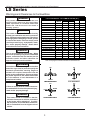
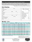
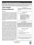
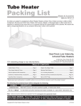
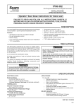
LS Series - 3” Tube Heater Installation, Operation, Maintenance and Parts Manual*
! WARNING: This heater must be installed and serviced by trained gas installation and service personnel only!
Improper installation, adjustment, alteration, service or maintenance can cause property damage, injury or death.
Read the installation, operating and maintenance instructions thoroughly before installing or servicing this equipment.
Protect yourself and others by observing all safety information. Retain instructions for future reference.
LS Series
* For complete installation instructions, see Generic IOM this piece was inserted within. Also available at www.reverberray.com.
Project: ____________________________ Date: _________________
Location: _________________________________________________
City: ________________________ State: _______ Zip: ___________
Customer Name: ___________________________________________
Local Representative: ______________________________________
Contractor: _______________________________________________
Engineer: _________________________________________________
Address: __________________________________________________
City: _________________________ State: ________ Zip: ___________
Phone#: ___________________________ Install Date: ____________
Serial#: ___________________________________________________
Notes: ____________________________________________________
Commercial Models
Model #
LS 10-25
LS 10-30
LS 10-40
LS 15-40
LS 15-50
LS 20-40
LS 20-50
LS 30-50
(circle one)
N or LP
N or LP
N or LP
N or LP
N or LP
N or LP
N or LP
N or LP
BTU's
25,000
30,000
40,000
40,000
50,000
40,000
50,000
50,000
Residential Models
Length
12'-3"
12'-3"
12'-3"
17'-0"
17'-0"
22'-0"
22'-0"
31'-3"
Model #
LS 10-25
LS 10-30
LS 15-40
LS 20-40
LS 30-50
(circle one)
N or LP
N or LP
N or LP
N or LP
N or LP
Models
1
Warnings
2
Clearances to Combustibles 2
Product Summary
3
Mechanical Instructions
3
Heater Requirements
4
Theory of Operation
4
Wiring Diagrams
5-7
Flowchart
8-9
Parts Listing
10-11
Series Kit Contents
12
U-Tube
Length
N/A
N/A
N/A
N/A
N/A
13'-0"
13"-0"
*17'-8"
Weight
70#
70#
70#
85#
85#
100#
100#
120#
Min.
Mount
Height
8 ft.
8 ft.
10 ft.
8 ft.
10 ft.
8 ft.
9 ft.
9 ft.
Combustion
Chamber
Titanium Coated
Titanium Coated
Titanium Coated
Titanium Coated
Titanium Coated
Titanium Coated
Titanium Coated
Titanium Coated
Radiant Emitter "Type" Tube Pkg Baffle
Tube
#1
Pieces
N/A
10-3 Titanium
3
N/A
10-3 Titanium
3
N/A
10-3 Titanium
3
Aluminized
15-3 Titanium
3
Aluminized
15-3 Titanium
3
Aluminized
20-3 Titanium
3
Aluminized
20-3 Titanium
3
Aluminized
30-3 Titanium
3
(Approved for both commercial and residential use)
Gas Type
Qty.
Page
(Approved for commercial use)
Gas Type
Qty.
Table of Contents
BTU's
25,000
30,000
15,000
40,000
50,000
U-Tube
Length Length
12'-3"
N/A
12'-3"
N/A
17'-0"
N/A
22'-0"
13'-0"
31'-3"
*17'-8"
Min.
Mount
Weight Height
70#
8 ft.
70#
8 ft.
85#
8 ft.
100#
8 ft.
120#
9ft.
Combustion
Chamber
Titanium Coated
Titanium Coated
Titanium Coated
Titanium Coated
Titanium Coated
*Model requires 5EA-Sub accessory package.
Warranty registration options:
1. Register online at www.reverberray.com/warranty
2. Fill out this page and fax to Detroit Radiant Products Co.
3. Fill out this page and mail a copy to Detroit Radiant Products Co.
Printed in U.S.A.
© 2004 Detroit Radiant Products
21400 Hoover Rd., Warren, MI 48089
T. (586) 756-0950 F. (586) 756-2626
Form# LIOLS-1M-3/04 (LES)
Replaces Form# LIOLS-2M-10/02
Radiant
Emitter Tube
N/A
N/A
Aluminized
Aluminized
Aluminized
"Type" Tube
Pkg #1
10-3 Titanium
10-3 Titanium
15-3 Titanium
20-3 Titanium
30-3 Titanium
Baffle
Pieces
3
3
3
3
3
LS Series - 3” Tube Heater Installation, Operation, Maintenance and Parts Manual
LS Series
Warnings and Clearances to Combustibles
!
WARNING!
Only certain models are for residential use.
Certified under American Gas Association
(AGA) requirement for residential radaint tube
heaters No. 7-89 Do not use in the home or
sleeping quarters.
!
WARNING!
This heater must be installed and serviced by
trained gas installation and service personnel
only. Read and understand these instructions
thoroughly before attempting to install, operate
or service this heater. Failure to comply could
result in personal injury, asphyxiation, death,
fire, and/or property damage. Retain these
instructions for future reference.
WARNING!
!
This is not an explosion-proof heater. Where
there is the possibility of exposure to flammable
vapors, consult the local fire marshal, the fire
insurance carrier and other authorities for
approval of the proposed installation.
!
LS (10) - 25,30
W/1 side shield
W/2 side shields
20 ft from burner
LS (10,15,20) - 40
W/1 side shield
W/2 side shields
20 ft from burner
LS (15) - 50
W/1 side shield
W/2 side shields
20 ft from burner
LS (20,30) - 50
W/1 side shield
W/2 side shields
20 ft from burner
SIDE
MOUNTING
ANGLE
FRONT BEHIND
0º
8
8
45º
39
8
0º
29
8
0º
9
9
0º
NA
NA
0º
15
15
45º
58
8
0º
42
8
0º
20
20
0º
NA
NA
0º
11
11
45º
39
8
0º
29
8
0º
16
16
0º
NA
NA
0º
11
11
45º
39
8
0º
29
8
0º
16
16
0º
7
7
TOP
BELOW
4
10
4
4
NA
6
10
6
6
NA
6
10
6
6
NA
6
10
6
6
6
36
36
36
36
NA
45
45
45
45
NA
48
48
48
48
NA
48
48
48
48
30
*See cover page for models certified for residential use.
SIDE
SIDE
FRONT
BEHIND
BELOW
BELOW
0º MOUNTING ANGLE
0º W/1 SIDE SHIELD
TOP
TOP
BEHIND
FRONT
WARNING!
This heater should be installed so that the
minimum clearances to vehicles, as marked
on the heater, will be maintained. If vehicle
lifts are present, ensure that these clearances
will be maintained from the highest raised
vehicle.
TOP
TOP
WARNING!
Failure to comply with the stated clearances
to combustibles could result in personal injury,
death and/or property damage.
!
MODEL NO.
WARNING!
In locations used for the storage of combustible
materials, signs must be posted to specify the
maximum permissible stacking height to
maintain the required clearances from the
heater to the combustibles. Signs must either
be posted adjacent to the heater thermostats
or in the absence of such thermostats in a
conspicuous location.
!
LS CLEARANCES TO COMBUSTIBLES (IN.) *
SIDE
SIDE
BELOW
BELOW
45º MOUNTING ANGLE
0º W/2 SIDE SHIELDS
2
LS Series - 3” Tube Heater Installation, Operation, Maintenance and Parts Manual
LS Series Mechanical Instructions
This supplement is designed to address the specifics of the LS Series - See page 12 for specific product features.
Product Summary
IMPORTANT
LS Series commercial/residential tube heaters are available from 10
to 30 foot, 25,000 through 50,000 BTU’s, natural or LP gas. LS
Series are positive pressure, single stage heaters and feature
aluminized steel for it’s radiant pipes.
LS MODELS
APPROVED VENT PACKAGES
25,000
thru
50,000 BTUH
3-DSK
RTVP-3
Figure 1
Specific Mechanical Instructions
Be sure to identify the titanium combustion chamber and place as the first tube section.
Do not use the aluminized steel radiant tubing as the first tube (combustion chamber).
Radiant
Tube
For residential installations it is required that the appliance be vented. Venting must
be 3 in. diameter (4 in. diameter for common venting). Refer to the flue venting guidelines,
figure 1 and on page 19 of the General Manual. For residential installations mounted
below 8 feet, it is required that Protective Guards (part # PG) are installed on heater
(see figure 2).
Reflector
Protective Guard
(part # PG)
Figure 2
LS BAFFLE INSTRUCTIONS
WITH TURBULATOR FINS
Insert assembled baffles with HEAT Baffle preceeding the
PRESSURE Baffles (fig. 1). Allow for turbulator fins so that
the key hole is inserted first. All baffles must be placed
vertically in the last radiant tube/heat exchanger (fig.2).
Figure 1
HEAT BAFFLE
1st
If the heater is installed with a U or Elbow fitting all baffle
must still remain. There may be some instances where the
baffle will be cut into two sections. Place as much baffle as
possible downstream of the U or Elbow and the remainder
of the baffle just before the U or Elbow fitting.
Key
Hole
2nd
PRESSURE BAFFLE
3rd
3'
BURNER BOX
TOP VIEW
Figure 2
IMPORTANT: NOTE FIN DIRECTION & BAFFLE ASSEMBLY
100º 80º
Turbulator fins
Key
Hole
LAST RADIANT TUBE
HEAT BAFFLE
PRESSURE BAFFLE
END VIEW
SIDE
VIEW
CROSS SECTION
WITH BAFFLE
Figure 3
3
LS Series - 3” Tube Heater Installation, Operation, Maintenance and Parts Manual
LS Series
Theory of Operation
Electrical Requirements
♦ 120 Volt - 60 HZ.
♦ Hot surface ignition.
♦ Starting Current 4.8 Amps.
♦ Running Current 1.1 Amps.
♦ 24V controls optional (24VAO).
·
Starting Circuit
When voltage is applied to L1 and L2 (see diagram
on right), a circuit is completed from L1 via the
blower motor to L2. The blower fan is mounted in
the control box and rated to supply sufficient air for
combustion.
Gas Requirements
♦ Manifold Pressure
• Nat. 3.5’’ • LP. 10.0’’
♦ Minimum Inlet Pressure
• Nat. 5.0’’ • LP. 11.0’’
♦ Maximum Inlet
• Nat. 14.0’’ • LP. 14.0’’
Air pressure generated by the blower will cause
the normally open burner pressure switch No. 1 to
close. Another circuit is completed from L1 to the
module ignition control and back to L2. There is a
five second delay, then the glo-bar is powered.
After the glo-bar has been powered for 45 seconds, the control module causes the gas valve to
open and initiates the ignition trial.
Ventilation Requirements
♦ Residential models must be vented.
♦ Consult the generic supplement for venting instructions
and unvented operation.
Power to the glo-bar is shut off during the last two
or three seconds of the ignition trial.
♦ For unvented operation (commercial use only), there must
be a positive air displacement of at least 4.0 CFM per
1000 BTU/H for natural gas or 4.5 CFM per 1000 BTU/H
for LP gas. WVE-4 termination cap must also be used.
·
♦ Maximum vent length for all models is 20 ft.
Running Circuit
After ignition, the flame rod monitors the flame. As
long as a flame is present, the valve is held open.
If the flame is lost, the control acts to close the valve
within one second, and a new trial sequence
identical to that at start-up is initiated. If proof of
flame is not established within 8.5 seconds, the
unit will lock out. If lockout occurs, the control can
be reset by briefly interrupting the power source.
Approved & Required Vent Caps
Sidewall Single
♦ 3’’ Duravent sidewall vent kit (3-DSK).
♦ 3’’ Vent terminal (SWD-3).
Sidewall Dual (Sharing common t-stat)
♦ 4’’ Duravent sidewall vent kit (4-DSK).
♦ 4’’ Vent terminal (SWD-4).
Roof Single
♦ Approved 3’’ rooftop raincap (RTVP-3).
Roof Dual (Sharing common t-stat)
♦ Approved 4’’ rooftop raincap (RTVP-4).
Important: Do not use sidewall caps for roof venting and do
not use roof caps for sidewall venting.
4
LS Series - 3” Tube Heater Installation, Operation, Maintenance and Parts Manual
Internal Wiring Diagrams
LADDER DIAGRAM - MARK17DU-117 WITH THERMO
L1
L2
120VAC
BLOWER
BK
BK
INDICATOR LIGHTS
BK
BK
BK
BK
GAS VALVE
BK
BK
THERMO
SWITCH
PRESSURE SWITCHES
R
BK
O
W
BK
W
G
GND
NEUT
VALVE
NEUT
TH
LINE1
PROBE
IGNITOR
SIC1
W
BR
IGNITION MODULE
IF ANY OF THE ORIGINAL WIRE AS SUPPLIED WITH THE APPLIANCE MUST BE REPLACED, IT MUST
BE REPLACED WITH WIRING MATERIAL HAVING A TEMPERATURE RATING OF AT LEAST 105 C.
BLOCK DIAGRAM - MARK17DU-117 WITH THERMO
BURNER
TERMINAL BLOCK
PRESSURE
SWITCHES
BK
BK
BK
FLAME
ROD
IGNITOR
BK
BK
THERMO
SWITCH
BK
BK
BK
BK
BR
O
INDICATOR
LIGHTS
BK
L1
BK
120VAC
BK
L2
W
W
BLOWER
W
W
M
1
C
2
P
3
M
1
C
2
P
3
MARK 17DU-117
W
R
GAS VALVE
5
IGNITION
MODULE
PROBE
SIC1
LINE1
TH
NEUT
VALVE
NEUT
GND
G
LS Series - 3” Tube Heater Installation, Operation, Maintenance and Parts Manual
LS Series
Field Wiring Diagrams
G
W R
Common required
for thermostats
that require
constant power.
24V
HEATER
BURNER BOX
24V
WHITE
L2
115V
L1
TO HEATER BRANCH #1
BY OTHERS
VIOLET
WHITE
115V
HEATER
BURNER BOX
TO HEATER BRANCH #2
BLACK
NOTE: This Transformer
Relay will handle up to 3
tube heaters per branch
(6 tube heaters total) or
up to 8 DR heaters per
branch (16 DR heaters
total)
HEATER
BURNER BOX
NOTE: Brown and
Yellow wires on the
R8285 transformer relay
are normally not used.
POLE
#2
POLE
#1
R
W
W
G
Y
B
COIL
C
RED/YELLOW
RED
R 8285 Transformer Relay - Used in
conjunction with any low voltage T-stat
(i.e. XL411, T8600) when wiring tube
heaters or line voltage DR heaters
24V T-Stat & Connection - Relay Tranformer Required
FIELD WIRING INSTRUCTIONS
HEATER
BURNER BOX
T-stat
NOTE: Up to 4 line
voltage tube heaters can
be wired to most T-stats.
Heaters on same vent
must share the same
t-stat.
GRD
NC
HEATER
BURNER BOX
COM
HEATER
BURNER BOX
L1
L2
120V Connection(s)
FIELD WIRING FOR MULTIPLE LINE VOLTAGE HEATERS
6
L2
115V
L1
LS Series - 3” Tube Heater Installation, Operation, Maintenance and Parts Manual
Alternative Wiring Diagrams
MARK17DU-117 WITH THERMO
TERMINAL BLOCK
PRESSURE
SWITCHES
BK
BURNER
BK
BK
BK
T-STAT
TERMINAL
BK
BK
BK
24V
BK
BR
O
BK
BK
FLAME
ROD
IGNITOR
THERMO
SWITCH
INDICATOR
LIGHTS
L1
BK
120VAC
BK
L2
W
W
BLOWER
W
W
M
1
C
2
P
3
M
1
C
2
P
3
MARK 17DU-117
W
IGNITION
MODULE
R
PROBE
SIC1
LINE1
TH
NEUT
VALVE
NEUT
GND
G
GAS VALVE
BLOCK DIAGRAM FOR INTERNAL RELAY OPTION
THE INTERNAL RELAY ALLOWS FOR LOW VOLTAGE T-STAT OPERATION OF LINE VOLTAGE HEATERS
COMMON REQUIRED FOR
THEMOSTATS THAT REQUIRE
CONSTANT POWER.
N
24v
N
24v
N
24v
COMMON C
BURNER BOX
WITH
INTERNAL
RELAY
OPTION
W
R
24v DIGITAL T-STAT
BURNER BOX
WITH
INTERNAL
RELAY
OPTION
EXTERNAL
TRANSFORMER
24V
120 V
EXTERNAL TRANSFORMER IS
NEEDED WHEN USING THE
INTERNAL RELAY OPTION. A
40VA TRANSFORMER IS
SUFFICIENT TO OPERATE 10
APPLIANCES
L2
L1
FIELD WIRING FOR INTERNAL RELAY OPTION
7
BURNER BOX
WITH
INTERNAL
RELAY
OPTION
8
Does valve open?
YES
Does valve light
come on?
YES
NO
NO
Remove obstruction
& lubricate fan.
Is the ignitor
physically damaged?
YES
NO
Correct problem.
Replace valve.
NO
YES
NO
Temporarily place jumpers across
the thermal fuse (be sure to reinstall
the cover). Does the light energize?
YES
Replace thermal fuse.
* Baffle(s) is in the tube(s) farthest
from the burner.
* Heater, fan blower, squirrel cage,
intake and exhaust are clean and
free from dirt and obstructions.
* The 4” air intake pipe does not
exceed 20 feet and/or 2 elbows.
* There is not a negative pressure
experienced at the area of air intake
(i.e. attic space, high-winds, very
tight building).
Replace the appropriate switch after
verifying the following:
YES
The heater is equipped with 2 safety pressure
switches. The burner switch in the blower
compartment is a normally open switch and
the exhaust switch in the gas valve
compartment is a normally closed switch.
Temporarily place jumpers across the terminals
of each switch, one at a time. (Be sure to
reinstall the cover.) Does the light energize?
NO
Replace burned out light.
The fan is faulty and
must be replaced.
Replace faulty light.
Replace ignitor.
NO
Is resistance through
the ignitor 45-400S.
Repair wiring.
YES
The circuit board and/or wiring harness
may be faulty and need to be replaced.
Replace circuit board.
NO
Correct wiring.
NO
Is there 120V
YES
coming to the fan?
Check for loose wiring or
resistance in hose connection
to pressure switch. Are they NO
ok?
NO
Check voltage at ignitor
during ignition
sequence (usually 30-45 YES
seconds after power to
the heater). Is it 120V?
Check to make sure pressure is
within min. & max. inputs as
indicated on AGA burner rating
label. Are both ok?
NO
Does burner ignite at
YES
all?
Replace ignitor.
YES
YES
Is the blower
obstructed?
Is the inlet or the outlet
of the unit obstructed NO
(i.e. ice, birds nest, dirt)?
YES
Remove obstruction.
NO
Find the source of the
electrical problem.
Is the power at the
heater 120V?
NO
Is the light
burnt out? If
so, replace.
NO
Does the ignitor warm NO
up and glow red?
YES
Does the switch NO
light energize?
YES
Does the fan
turn on?
Turn up thermostat
LS Series Troubleshooting Flow Chart
LS Series - 3” Tube Heater Installation, Operation, Maintenance and Parts Manual
9
YES
YES
Test for 120V at valve
during valve opening
period (usually 30-45 NO
seconds after power
to the heater). Is there
120V to valve?
NO
NO
Troubleshooting
ends.
The following can cause the
heater to shut down:
* Improper grounding.
* High winds.
* Taking combustion air from
the attic.
* Dirty environment.
* Baffle not located properly.
* Fluctuating gas pressure.
NO
YES
WARNING: By-passing any
pressure switch is for testing
purposes only. Do not leave
switch by-passed during normal
operation or heater’s built-in safety
mechanisms will be compromised.
Sensing rod is faulty or flame is
weak. Check to make sure heater
is operating at proper gas
pressure as indicated on AGA
burner rating label and then
replace sensing rod if needed.
NO
Check to make sure
flame sensor wire is
ok and then replace
circuit board.
YES
With voltmeter, check DC
voltage at flame rod. Is it
greater than 30 Volts DC?
Certain models have a separate glo-bar
ignitor and flame rod sensor located next to
the glo-bar. Other models have a glo-bar
ignitor only, which acts as both an ignitor
and flame sensor. Does model in question
have glo-bar ignitor only?
YES
NO
Consult factory for
proper parts.
Exhaust pressure
switch may be
faulty or there is a
restriction in the
exhaust.
Correct
problem.
Correct problem.
NO
*
Make sure gas lines were
purged of air.
Correct
problem.
Is the heater properly grounded? YES
Is the heater’s polarity correct?
NO
Check to make sure that the pressure
is within minimum and maximum
inputs as indicated on the AGA
burner rating label. Is gas pressure YES
ok?
YES
Does the burner
come on and then
turn off immediately
(1 or 2 seconds).
NO
Does the burner stay on
for approx. 8 seconds and
then shut off?
Is the gas cock in YES
an ON position?
Check to make sure gas pressure is NO
within minimum and maximum
inputs, as indicated on AGA burner
rating label. Is gas pressure ok? YES
Replace
gas valve.
Correct
problem.
Possibly, the circuit
board and/or wiring
harness is faulty. These
should be replaced.
Check to make sure gas pressure is NO
within minimum and maximum
inputs, as indicated on AGA burner
rating label. Is gas pressure ok? YES
Does heater stay on
until call for heat ends?
YES
Does the burner
stay on?
YES
Does the burner
ignite?
YES
After ignitor is
warmed up, does gas NO
valve open?
YES
LS Series - 3” Tube Heater Installation, Operation, Maintenance and Parts Manual
328
70
10
333
329
334
44
264E
33B
122
351A
1064B
1002
264F
264D
31B
68A
352A
1063
1015
55A
76
212
83
208
223
209P
209
31B
330
1004
331
204
1060F
217
17
1062
1003
1033
1060D
1070
301
1
205
5
50
1080
1079
9
106
10
105
112
12
222A
20C
222
221
1078
11
1077
1081
mb
Co
n
tio
us
1086
be
Tu
rT
itte
Em
1082
e
ub
1083
LS Series - 3” Tube Heater Installation, Operation, Maintenance and Parts Manual
Parts Breakdown
LS Series
TP#
11
ITEM
CONTROL BOX COVER
FLANGE GASKET
CONDUIT COUPLING
CONDUIT 4" X 1/2"
GLO-BAR IGNITOR BOX
GLO-BAR IGNITOR BOX COVER
SIGHT GLASS KIT
120" ALUMINUM REFLECTOR
CONTROL BOX BRACKET
1/2" GAS COCK
AIR ORIFICE W/SCREEN - CONSULT FACTORY
GLO-BAR IGNITOR
FAN BLOWER (40, 50, 60 MBTU/H)
STRAIN RELIEF BUSHING
CONTROL BOX COVER GASKET (PER FOOT**)
RUBBER GROMMET
STAINLESS STEEL FLEX CONNECTOR
REFLECTOR END CAP
REFLECTOR CLIP
5' REFLECTOR
GASKET FOR AIR ORIFICE & AIR COLLAR
GAS ORIFICE - CONSULT FACTORY
GLO-BAR HOLDER
"Z" MOUNTING BRACKET
36E36A-246 GAS VALVE - NAT GAS ASSY
36E36A-240 GAS VALVE - LP GAS ASSY
1/2" X 3" PIPE NIPPLE
PRESSURE BARB FITTING
GLO-BAR HOLDER GASKET
FLAME ROD
FLAME ROD WIRE
GAS MANIFOLD
TP#
TP-264D
TP-264E
TP-264F
TP-301
TP-328
TP-329
TP-330
TP-331
TP-333
TP-334
TP-351A
TP-352A
TP-1002
TP-1003
TP-1004
TP-1015
TP-1033
TP-1060D
TP-1060F
TP-1064B
TP-1062
TP-1063
TP-1070
TP-1077
TP-1078
TP-1079
TP-1080
TP-1081
TP-1082
TP-1083
TP-1086
** 6’ TOTAL NEEDED TO COVER OUTER EDGES OF A BURNER BOX (TP-70).
TP-1
TP-5
TP-9
TP-10
TP-11
TP-12
TP-17
TP-20C
TP-31B
TP-33B
TP-44
TP-50
TP-55A
TP-68A
TP-70
TP-76
TP-83
TP-105
TP-106
TP-112
TP-122
TP-204
TP-205
TP-208
TP-209
TP-209P
TP-212
TP-217
TP-221
TP-222
TP-222A
TP-223
ITEM
N.O. BURNER PRESS. SWITCH (30MBTU/H)
N.O. BURNER PRESS. SWITCH (25MBTU/H)
N.O. BURNER PRESS. SWITCH (40 MBTU/H)
DIVIDER PANEL W/ P.S. MOUNTING TABS
120V INDICATOR LIGHT
1/4" NEUTRAL TERMINAL BLOCK
DIVIDER GROMMET
GREEN SELF TAP GROUND SCREW
3' BLACK 120V PLUG
YELLOW 24V CONTROL WIRE
MARK 17DU-117 POTTED CIRCUIT BOARD
LONG WIRING HARNESS FOR 17DU-117
LEFT END PANEL W/ LIGHT HOLES
RIGHT END PANELS - NO HOLES
CONTROL BOX
FAN BLOWER (25, 30 MBTU/H)
THERMAL FUSE
EXHAUST PRESS. SWITCH (25,30 MBTU/H)
EXHAUST PRESS. SWITCH (40,50 MBTU/H)
N.O. BURNER PRESS. SWITCH (50 MBTU/H)
EXHAUST PRESSURE TUBE (VINYL)
1/4" ATMOSPHERIC & PRESSURE TUBES (VINYL)
BURNER (25 TO 50 MBTU/H)
TUBE CLAMP
REFLECTOR CENTER SUPPORT
WIRE HANGER W/ SPRING CLIP
16'' BURNER TUBE WITH FLANGE
10 FT. TITANIUM COMBUSTION TUBE
10 FT. STAINLESS RADIANT TUBE
3" S.S. INTERLOCKING 33" PRESSURE BAFFLE WITH TABS
3" S.S. INTERLOCKING 33" HEAT BAFFLE SECTION
LS SERIES PARTS LISTING
Basic Parts List
LS Series - 3” Tube Heater Installation, Operation, Maintenance and Parts Manual
LS Series - 3” Tube Heater Installation, Operation, Maintenance and Parts Manual
KIT CONTENTS AND PRODUCT FEATURES
Kit contents for the LS Series are shown below. Reference the proper column for your particular models length.
FILLED BY:
LS SERIES KIT CONTENTS
TP#
DESCRIPTION
10 FOOT
15 FOOT
20 FOOT
30 FOOT
TP-1077
TP-1079
TP-1078
TP-105
TP-106
TP-33B
TP-83
3" TUBE CLAMPS
3" HANGERS
3" REFL. CNTR. SPRT.
REFL. ENDCAPS
REFL. ENDCAP CLIPS
1/2" GAS COCK
24" SS FLEX LINE
1
2
1
2
8
1
1
2
3
1
2
8
1
1
2
3
2
2
8
1
1
3
4
3
2
8
1
1
IOM
INSTALL / OP MANUAL
1
1
1
1
3” Hanger
TP-1079
3” Butt Clamp
TP-1077
1/2” Gas Cock
TP-33B
Reflector End Caps
TP- 105
3” Reflector Center Support
TP-1078
24” SS
Flex
Connect
TP-83
Bag of Reflector
endcap clips
TP-106
General IOM
(LIOGT)
AND
Series Insert
(LIOLS)
Product Features
APPROVALS
• IAS, CGA, AGA, CSA.
• Certain models are residentially
certified to AGA No. 7-89.
• Outdoor Approval with OD-KIT.
BURNER SIGHT GLASS
• For burner inspection.
COMBUSTION AIR INLET & VENT
• 4” air inlet duct.
• 3” vent duct.
ENAMELED CONTROL BOX
• Outside air collar (4”) attached.
• Totally enclosed components.
EMMITER & COMBUSTION TUBES
• 16ga. 3” O.D. titanium coated
combustion chamber.
• 16ga. 3” O.D. aluminized steel radiant
tubes.
OPTIONAL FEATURES
• 24VAO - Used when operating heater
with 24V thermostat. Includes internal
relay, power cord and indicator lights.
External transformer required.
CONTROLS
• 100% safety shut off.
• Moisture and corrosion resistant
GAS CONNECTION
ignition module.
• 1/2” gas cock included.
• Dual differential pressure switches.
• 24” x 1/2” flex connector included.
• Silicon carbide hot surface igniter.
• Flame rod sensing.
• Pre-purge controls.
• Indicator lights.
12
RADIANT SURFACE AREA (SQ. FT.)
• 10’ models - 7.6
• 20’ models - 15.2
• 30’ models - 22.8
WARRANTY*
• 1 year - Burner box components.
• 3 years-Combustion and radiant
tubes.
• 5 years-Stainless steel burner.
* See cover for warranty registration
information.
OTHER
• One reflector center support per
reflector.
• Stainless steel turbulator baffle
included.
• Stainless steel upgrades (burner box
and reflectors only) are available.
• Silicone sealed control box available.
• Made in U.S.A.
• Visit www.reverberray.com for
additional information & parts.