1
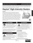
Installation, Operation, Maintenance and Parts Manual
DR Series
! WARNING: This heater must be installed and serviced by trained gas installation and service personnel only!
Improper installation, adjustment, alteration, service or maintenance can cause property damage, injury or death.
Read the installation, operating and maintenance instructions thoroughly before installing or servicing this equipment.
Protect yourself and others by observing all safety information. Retain instructions for future reference.
Detroit Radiant Products Company
- DR Series -
!
!
WARNING!
Improper installation, alteration, service or maintenance
can cause property damage, injury or death. Read the
installation, operating and maintenance manual
thoroughly before installing or servicing this equipment.
! WARNING - NOT FOR RESIDENTIAL USE
This heater is NOT approved for use in any residential
application. This includes (but is not limited to) attached
garages, solariums, living quarters, etc. Consult the
local fire marshal and/or insurance provider if unsure of
your application.
WARNING!
This heater must be installed and serviced by trained gas
installation and service personnel only. Read and
understand these instructions thoroughly before attempting
to install, operate or service this heater. Failure to comply
could result in personal injury, asphyxiation, death, fire,
and/or property damage. Retain these instructions for
future reference.
!
WARNING!
This is NOT an explosion proof heater. Where there is
the possibility of exposure to flammable vapors, consult
the local fire marshal, the fire insurance carrier and other
authorities for apporval of the proposed installation.
FOR YOUR SAFETY
Do not store or use gasoline or other flammable vapors
and liquids in the vincinity of this or any other appliances.
FOR YOUR SAFETY
What to do if you smell gas:
!
WARNING!
In locations used for the storage of combustible materials,
signs must be posted to specify the maximum permissible
stacking height to maintain the required clearances from
the heater to the combustibles. Signs must either be posted
adjacent to the heater thermostats or in the absence of such
thermostats in a conspicuous location.
Form# LIODR-10M-09/04 (ID)
Replaces Form# LIODR-7.5M-02/04
• Do not try to light any appliance.
• Do not touch any electrical switch or use
any phones in your building.
• Immediately call your gas supplier from
a neighbor’s phone. Follow the gas
supplier’s instructions.
• If you cannot reach your gas supplier,
call the fire department.
Printed in U.S.A.
© 2004 Detroit Radiant Products Co.
21400 Hoover Rd., Warren, MI 48089
T. (586) 756-0950 F. (586) 756-2626
www.reverberray.com
å
DR Series
Installation, Operation, Maintenance and Parts Manual
Detroit Radiant Products Company
CAUTION!
The following information should be reviewed
before installing this heater:
•
•
•
•
Check the AGA rating label on the heater to verify •
model number. Check and maintain the attached
minimum clearance to combustibles label and the
proper gas to be used. Check all labels on the
heater to verify proper mounting.
•
The installation of this heater must conform with
local building codes or, in the absence of local
codes, with the National Fuel Gas Code, ANSI
Z223.1-1999 (NFPA 54-current edition).
•
The installation of this heater in public garages
must conform with the Standard for Parking
Structures, ANSI / NFPA 88A-current edition: or
the Standard for Repair Garages, ANSI / NFPA •
88B-current edition, and must be at least 8 ft.
above the floor while maintaining all clearances
to combustibles.
•
The installation of this heater in aircraft hangars
must conform to the Standard for Aircraft
Hangars, ANSI / NFPA 409-current edition. The
heater must be installed at least 10 ft. above the •
upper wing surfaces and engine enclosures of
the highest aircraft which might be stored in the
hangar. In areas adjoining the aircraft storage
area, the heaters must be installed at least 8 ft.
above the floor. The heaters must be located in •
areas where they will not be subject to contact by
aircraft, cranes, moveable scaffolding or other
objects.
2
If an external electrical source is utilized, the
heater must be electrically grounded in
accordance with the National Electrical Code,
ANSI / NFPA70-current edition.
Under no circumstance is either the gas supply
line or the electrical supply line to the heater to
provide any assistance in the suspension of the
heater.
The weight of the heater must be entirely
suspended from a permanent part of the building
structure having adequate load characteristics.
Neither the gas supply line, electrical supply line
nor sprinkler heads shall be located in or near
the path of the flue products from the heater.
This heater cannot be used in a building with an
uninsulated roof or condensation problems could
result.
Where this heater is used, natural or mechanical
means shall be provided to supply and exhaust
at least 4.0(Nat.) or 4.5(LP) C.F.M. per 1000 BTU/
H of the heater’s rated input.
Signs should be posted in storage areas to
specify maximum stacking height allowed in order
to maintain clearance to combustibles.
Clearance safety limit plaques (PLQ), available
from Detroit Radiant Products are recommended
for this purpose.
DR Series
Installation, Operation, Maintenance and Parts Manual
DR Series Heaters
WARNING!
WARNING!
Failure to comply with the stated clearance to
combustibles could result in personal injury, death
and/or property damage.
This heater should be installed so that the minimum
clearance to combustibles, as marked on the
heater, will be maintained. If vehicle lifts are
present, ensure that these clearances will be
maintained from the highest raised vehicle.
CLEARANCES TO COMBUSTIBLES [IN.]
Model No.
DR 30 (S)
DR 45
DR 50
DR 55
DR 60
DR 75
DR 80
DR 85
DR 90
DR 95
DR 100
DR 130
DR 160
Sides
30
30
30
32
32
48
48
48
48
48
48
48
50
Back
18
18
18
18
18
30
30
30
30
30
30
30
32
Top
28
28
34
40
40
42
42
42
42
52
52
52
60
Below
72
72
72
72*
72*
98
98
98
98
120
120
120
132
* This clearance is 80 in. when the heater is fitted with a parabolic reflector.
Figure 1.1 CLEARANCE-TO-COMBUSTIBLES CHART
NOTE: If the heater is mounted beneath a non-combustible surface a 24 in. minimum top clearance
must be maintained from the top of the heater to prevent overheating the controls.
Figure 1.2 CLEARANCE-TO-COMBUSTIBLES DIAGRAM
3
å
DR Series
Installation, Operation, Maintenance and Parts Manual
Detroit Radiant Products Company
1.1 DESIGN
1.2 LAYOUT
When positioning heater, keep in mind the clearance
to combustibles with materials such as, lights,
sprinkler heads, overhead doors, storage areas with
stacked materials, gas and electrical lines, parked
vehicles, cranes, etc. Refer to Figure 1.1 on page 3
for minimum clearance to verify that a safe installation
condition exists.
Perimeter mounting of these infrared heaters
provides for the most efficient installation. In Figure
1.5, the heaters are mounted around the perimeter
of the space to be heated. Refer to the Installation
Chart for the recommended distances on the models
being installed.
Buildings that require the rows of heaters to be farther
apart than the recommended distance in the
Installation Chart may need additional heaters placed
in the center of the space as in Figure 1-5.
In locations used for the storage of combustible
materials, signs shall be posted to specify the
maximum permissible stacking height to maintain
required clearances
from the heater to the
combustibles.
Typical exhauster, air intake louver and thermostat
location is also shown on the sample buildings in
Figure 1.5.
DR SERIES SPOT HEATER LOCATION CHART
“B” DIM.
APPROX.
DISTANCE CENTERS FOR
BEHIND
FULL
APPROX.
RECOMMENDED MOUNTING HEIGHT
MAN OR COVERAGE
DIMENSIONS APPROX.
MODEL
(“A” DIM.)
WORK (SPOT & AREA)
SQ. FT.
OF AREA
TYPE AREA
&
COVERED COVERED 10’ 12’ 14’ 16’ 18’ 20’ 22’ 24’ 26’ 28’ 30’ STATION HTG. ONLY
(SURROUNDINGS)
INPUT
9’
4’
10’
100
10’ X 10’
COLD/DRAFTY
DR-30
10’ 12’
5’
12’
144
12’ X 12’
AVERAGE
30,000
12’ 14’
6’
14’
196
14’ X 14’
BTU/H PROTECTED/INSUL.
10’ 12’
5’
12’
144
12’ X 12’
COLD/DRAFTY
DR-45
6’
14’
196
14’ X 14’
AVERAGE
45,000
7’
16’
256
16’ X 16’
BTU/H PROTECTED/INSUL.
12 14’
6’
256
16’
16’ X 16’
COLD/DRAFTY
DR-60
14’ 16’
324
7’
18’
AVERAGE
18’ X 18’
60,000
16’ 18’
8’
20’
20’ X 20’
400
BTU/H PROTECTED/INSUL.
14’ 16’
7’
324
18’
18’ X 18’
COLD/DRAFTY
DR-75
16’ 18’
8’
22’
484
AVERAGE
22’ X 22’
75,000
18’ 20’
9’
24’
26’ X 26’
676
BTU/H PROTECTED/INSUL.
16’ 18’
400
9’
20’
20’ X 20’
COLD/DRAFTY
DR-90
18’ 20’
10’
576
24’
24’ X 24’
AVERAGE
90,000
20’
11’
784
26’
28’ X 28’
BTU/H PROTECTED/INSUL.
18’
10’
24’
576
COLD/DRAFTY
24’ X 24’
DR-100
18’ 20’
11’
26’
28’ X 28’
784
AVERAGE
100,000
20’
12’
1024
30’
32’ X 32’
BTU/H PROTECTED/INSUL.
18’
11’
26’
676
COLD/DRAFTY
26’ X 26’
DR-130
18’ 20’
12’
28’
30’ X 30’
900
AVERAGE
130,000
20’ 22’
1225
13’
32’
35’ X 35’
BTU/H PROTECTED/INSUL.
20’ 22’
12’
784
28’
28’ X 28’
COLD/DRAFTY
DR-160
24’ 26’
16’
1225
32’
35’ X 35’
AVERAGE
160,000
28’ 30’
20’
35’
1600
40’ X 40’
BTU/H PROTECTED/INSUL.
Figure 1.3
4
DR Series
Installation, Operation, Maintenance and Parts Manual
DR Series Heaters
HEATER INSTALLATION CHART
Model No.
DR 30(S)
DR 45
DR 50
DR 55
DR 60
DR 75
DR 80
DR 85
DR 90
DR 100
DR 130
DR 160
Mounting Heights (Dimension A)
30 ° Angle
30 ° Angle
Standard
Parabolic
Reflector
Reflector
[ft]
[ft]
12-14
12-15
12-14
16-19
12-14
17-20
13-15
18-21
14-16
18-21
15-17
19-22
15-17
19-22
16-18
21-25
16-18
21-25
17-20
23-27
21-24
26-32
24-28
29-35
Distance
Between
Heaters
(Dimension B)
[ft]
8-30
14-40
14-40
14-43
15-43
16-50
16-50
16-55
20-55
20-60
22-65
25-70
Distance
Between
Heater Rows
(Dimension C)
[ft]
10-70
14-80
14-80
14-90
15-90
20-100
20-100
20-110
20-110
20-120
23-140
25-160
Distance
Between
Heater
and Wall
[ft]
6
10
10
10
12
12
12
12
12
12
14
14
Figure 1.4
NOTE: The chart above is provided as a guideline only. Actual conditions may dictate variation from the data shown.
/
C
B
B
B
A
NOTE: Dimensions A, B and C refer to figure 1.4
Figure 1.5
5
å
DR Series
Installation, Operation, Maintenance and Parts Manual
Detroit Radiant Products Company
•
2.1 HEATER MOUNTING
•
Figure 2.1 illustrates the more common method
for heater mounting. Some local codes or
application conditions, such as drafts or other
variables that could cause the units to move,
stipulate that if flexible gas connectors are used
then the heater must be rigidly mounted (see
Figure 2.2). Consult local codes for further details.
Heater must be level from side to side (see Figure
1.2 on pg. 3). The units must be mounted at a
20° to 35° angle from horizontal, so the controls
(or manifold end) are located at the lower end
(Figure 2.3-2.5). Gas and electrical lines must not
be located above the path of exhaust. See figure
6-1 on page 11 for path of exhaust.
Steel “C” Clamp
Steel “C” Clamp
Threaded Rod
Chain Hanging Set
Disconnect Switch
Clevis Hanger
Flue Products Discharge Here
Drip Leg
Figure 2.3 BURNER ASSEMBLY RELATION
TO GROUND LEVEL
20º - 35º
325-3 Regulator
Proper
AGA Ball Valve
Incorrect
AGA Flexible Gas Connector
Optional 325-3 regulator required
where gas supply pressure
exceeds 14” W.C.P
Do not install gas piping
or electrical wiring above
flue discharge area.
(not to scale)
Figure 2.1 TYPICAL HEATER MOUNTING
Figure 2.4 BURNER ASSEMBLY RELATION
TO GROUND LEVEL
Location of
control box
is incorrect.
Figure 2.2 RIGID HEATER MOUNTING
Figure 2.5 BURNER ASSEMBLY RELATION
TO GROUND LEVEL
6
DR Series
Installation, Operation, Maintenance and Parts Manual
DR Series Heaters
3.1 GAS SUPPLY
MANIFOLD PRESSURE CHART
Required
Manifold
Pressure (WCP)
Minimum
Inlet Pressure
(WCP)
Maximum
Inlet Pressure
(WCP)
Natural Gas
6.0 in.
7.0 in.
14.0 in.
Liquified
Petroleum Gas
10.0 in.
11.0 in.
14.0 in.
CAUTION!
CORRECT INLET PRESSURES ARE VITAL FOR
EFFICIENT OPERATION OF HEATER. REFER TO
AGA/CGA RATING PLATE AND, IF NECESSARY,
CONSULT GAS COMPANY.
Figure 3.1
If all or a portion of the gas supply line consists of used
pipe, it must be cleaned and then inspected to determine
its equivalency to new pipe. Test all main supply lines
according to local codes. (Isolate heater gas valve and
supplied gas cock during test.)
Use only a pipe joint compound that is resistant to liquified
petroleum gases.
Excessive torque on the manifold may misalign the
orifice(s). Always use two wrenches when tightening
mating pipe connections.
Gas Line Connection
The following guidelines must be observed to ensure
proper system performance and safety:
•
WARNING!
Never use a match or any other flame to test for
gas leaks. Use a soap and water solution to check
for leaks.
•
•
•
If any portion of the gas supply line is located in an area
that could cause an abnormal amount of condensate to
occur in the pipe, a sediment trap should be installed.
NOTE: For high pressure gas above 14 in. W.C.P.
(Water Column), a high pressure regulator and gas cock
must be used. If compressed air is used to detect leaks
in the gas supply line, disconnect and cap shutoff cock
to avoid damage to regulator and gas valve.
•
•
•
A sediment trap in the gas line will decrease the
possibility of any loose scale or dirt in the supply line
entering the heater’s control system and causing a
malfunction. Provide a 1/8 in. (3.2mm) NPT, plugged
tapping accessible for test gauge connection
immediately up stream of gas connection to heater.
Consult gas company for the proper pipe sizing. The
gas supply line must be of sufficient size to provide the
required capacity and inlet pressure to the heater (see
figure 3.1).
•
•
The use of a stainless steel, flexible gas connector
is recommended. If, however, local codes require
rigid piping to the heater, a swing joint can be used.
The gas outlet shall be in the same room as the
appliance and the connector must not be concealed
within or run through any wall, floor or partition.
The connector shall be of adequate length.
The final assembly shall be tested for leaks.
CAUTION: Matches, candles, open flame or other
sources of ignition shall not be used for this purpose.
Leak test solutions may cause corrosion-water rinse
after test.
Contact with foreign objects or substances should
be avoided.
The connector should not be kinked, twisted or
torqued.
Connectors are for use only on piping systems
having fuel gas pressures not in excess of ½ pound
per square inch or 14.0 in. W.C.P.
Neither the gas pipe nor flexible gas connector shall
be placed in the ‘flue discharge area’. See Fig. 2.1.
Bending, flexing and vibration to the gas connections
must be avoided to prevent failure.
CAUTION!
CONNECTOR NUTS MUST NOT BE CONNECTED
DIRECTLY TO PIPE THREADS. THIS CONNECTOR
MUST BE INSTALLED WITH ADAPTORS PROVIDED.
DO NOT REUSE.
NOTE: Manifold pressure should be checked at the tap
on the gas valve. Readings will be above atmospheric
pressure (during operation).
7
å
DR Series
Installation, Operation, Maintenance and Parts Manual
Detroit Radiant Products Company
4.1 ELECTRICAL
For wiring of controls on the unit see the wiring
diagram included on the provided insert.
WARNING!
The unit, when installed, must be electrically
grounded in accordance with the most current
national electrical code, ANSI/NFPA-70, when an
external source is utilized.
It is recommended that the thermostat be installed
on the hot side of a fused supply line and have a
sufficient ampere capacity rating for the heater(s) it
will control.
Control systems are energized by either 120 VAC,
24 VAC or millivolt energy. The 120 VAC systems
can be used directly from a 120 VAC line. On 24
VAC systems, transformers must be used to supply
power of sufficient VA rating for single or multiple
connected installations.
The ventilation system may be controlled separately
from the heating system (consult local codes) by use
of a humidistat that closes on a rise in humidity. The
humidistat control should be installed at roof level.
For summer ventilation, a simple on/off switch can
be installed at the occupant level.
Millivolt systems require NO external power, as energy needed to operate the valve is developed by
the power-pile generator. Do not use multiple connections, as one thermostat may only control one
heater.
OPERATION
Upon satisfactory completion of the electrical supply
and the purging of the gas supply line to the heater(s),
follow the “Lighting Instructions” on the heater’s rating
label to put heater into operation.
Important: Proper grounding and polarity are
essential for heaters with spark ignition controls. If
the system is not properly grounded, it cannot
determine the presence of a flame and will lockout
and shut off.
DR
S
H e eries
ate
r
Note: Do not attempt to ignite a direct spark ignition
heater by hand.
DR
S
H e eries
ate
r
T-Stat
Figure 4.1 TYPICAL FIELD WIRING
8
DR
S
H e eries
ate
r
DR Series
Installation, Operation, Maintenance and Parts Manual
DR Series Heaters
NFS-2/PFS-2 (24V)
Spark Electrode Part
Number - 32-508
Combination Gas Valve
Part Number
VR8205A-2123 for NG
VR8205A-2081 for LP
24 V SCHEMATIC
Direct Spark Ignition
L2
White Sensing Wire
Part Number
LVW-18
24V
VA Draw : 12
Amps : .48
Orange High Voltage Wire
Part Number - HVW-18
(Regular Circuit Board)
L1
Ignition Module Part Number
Mark 10X-24
Figure 4.2
MV
MV
S PA R K E LE C T R O D E
P A RT NUM B E R 32-508
W HITE
B LA CK
VA Draw : 12
Amps : .48
(Potted Circuit Board)
(sold separately)
C O M B INA TIO N G A S V A LVE
P AR T N U M B E R
V R8205A -2123 for NG
V R8205A -2081 for LP
NFS-2/PFS-2 (24V)
24 V SCHEMATIC
Direct Spark Ignition
Thermostat 24V
separately)
or(sold
Open/Close
O RA NG E HIG H V OLT AG E W IR E
P A R T N U M B E R H V W -18
T HE RM OS T AT
24V or O P EN /CLOS E
VA LVE
T-STAT
N EU TR AL
G R O UN D
HV
L1
24 V
L2
SE NS E
IG NIT ION M O DULE
P A R T N U M BE R
M A RK 10D X -24 (P otted)
Figure 4.3
NFS-2/PFS-2 (120V)
W IR E H A R N E S S
PART N UM B ER DRW H-24
Spark Electrode
Part Number 32-508
Combination Gas Valve
Part Number
VR4205M-1308 for NG
VR4205M-1316 for LP
WHITE
BLACK
120 V SCHEMATIC
Direct Spark Ignition
Thermostat 120V
or Open/Close
VA Draw : 12
Amps : .10
(Potted Circuit Board)
Figure 4.4
(sold separately)
Orange High Voltage Wire
Part Number HVW-18
Ignition Module Part Number
Mark 10DX-117
Wire Harness
Part Number
DRWH-120
9
å
DR Series
Installation, Operation, Maintenance and Parts Manual
Detroit Radiant Products Company
NMV-2/PMV-2
Combination Millivolt
Gas Valve
Millivolt
Thermostat
Gas Valve Number VS 820A-1070 for N.G.
VS 820A-1740 for LP
(supplied with heater)
750 MV SCHEMATIC
(supplied with heater)
750 MV Powerpile
(millivolt control)
Powerpile Part Number Q313A-1014
Figure 4.5
5.1 Ventilation
It is required that the upper levels of the space to be
heated are properly ventilated to supply combustion
air to the heaters and to sufficiently dilute the products
of combustion. This also prevents excessive humidity
buildup. With heaters mounted overhead and a
properly designed ventilation system, products of
combustion and excessive drafts will never be
present at occupancy levels.
For proper ventilation, a positive air displacement
of 4.0 CFM per 1000 BTU/H of natural gas
consumed must be provided. If propane is used, a
positive air displacement of 4.5 CFM per 1000
BTU/H of propane gas consumed must be provided.
Many large industrial buildings have sufficient air
movement to satisfy these dilution requirements.
However, in tightly constructed buildings where
insufficient air movement exists, induced air
displacement is required. This air displacement may
be accomplished by either gravity or mechanical
means. Provisions must be made to provide
sufficient fresh air intake area and exhaust air outlet
area. This is essential to provide a balanced system
to avoid negative building pressure which cause
excessive infiltration and unfavorable drafts thereby
affecting efficient combustion of infrared heaters.
Mechanical exhausters are preferred and typically
mounted at high points of the building on areas of
the roof where stagnant air can accumulate under
the deck. For a flat roof, considerations of prevailing
winds, high and low pressure areas, and distribution
of air movement must be taken into consideration
when locating exhausters.
Best air distribution is accomplished by using a
number of small exhausters versus one large
exhauster. Provide a minimum of one square inch
of net free inlet area per 1000 BTU/H for
combustion air supply. Inlet opening in the building
should be well distributed high in the sidewalls and
should direct incoming air upward to dilute products
of combustion while preventing drafts at lower levels.
Inlets are typically 1 to 3 sq. ft.
Local codes may require that mechanical exhaust
systems be interlocked with heaters to enable both
to function simultaneously (Figure 4.1 on pg.8). Other
codes may allow control of exhausters with a ceiling
mounted humidistat. Exhausters then operate when
relative humidity rises above humidistat setting.
Since the products of combustion increase the
relative humidity level of the space, this is a feasible
method of controlling exhausters. Selection of a
humidistat setting will vary with different conditions
and areas of the country.
10
DR Series
Installation, Operation, Maintenance and Parts Manual
DR Series Heaters
Main Burner
1. Use an air hose to blow any accumulated dust
and/or dirt off the heater. Air hose pressure
should not exceed 30 psig.
2. Pass the air hose over the entire exposed area of
the ceramic. A distance of 2’ to 4’ from the unit
is recommended.
3. Place the air hose outlet into each venturi tube and
allow the air to flow for approximately one minute.
4. See troubleshooting chart (pg. 12) if there are any
signs of burner malfunction. Replace if necessary.
6.1 MAINTENANCE
WARNING!
Disconnect all power sources related to the installation
before servicing any component.
WARNING!
Use protective glasses when cleaning the heater. If
the control assembly is not completely disconnected
from the manifold, the high air pressure will cause the
controls to become defective.
It is recommended that the following become a standard
yearly procedure to obtain maximum operating efficiency
and trouble free operation.
During long periods of non-usage, remove or cover
heater with a polyethylene bag and shut off gas supply.
If further service to the heater is desired, contact your
representative or the factory.
Pilot Burner
1. Remove pilot access door.
2. Use an air hose and blow the pilot burner free of
dust.
Gas Supply
1. Periodically inspect the gas supply for signs of
corrosion or failure. Replace if necessary.
6.2 HEATER ASSEMBLY COMPONENTS
For complete information on DR
Series replacement parts, consult
the DR Series Parts Price List.
This list includes information on
valves, igniters, circuit boards,
etc. for most recent models. For
other models, consult factory.
PATH OF EXHAUST
Note: Replacement burners are
called "rayheads" with rod inserts
(Part # DR-RH and DR-ROD).
Note: Ceramic grids are not sold
separately, order DR-RH. For
additional parts information visit
www.reverberray.com/parts.
DR 16-30
DR 45-60
DR 75-100
DR 130
DR 160
(1) DR-RH
(2) DR-RH
(3) DR-RH
(4) DR-RH
(5) DR-RH
DR SERIES UNVENTED GAS-FIRED INFRA-RED HEATER ASSEMBLY
Figure 6-1
11
å
SYM PTOM
CODE
7.1 TROUBLESHOOTING
B u rn in g o f g a s -a ir m ix tu re
in s id e p le n u m (fla s h b a c k ).
D e la ye d ig n itio n .
L o w c e ra m ic s u rfa c e
te m p e ra tu re , e x c e s s iv e
ro llo u t o r s o o t o n ro d s .
C o n tro l s ys te m o v e rh e a tin g .
P O S S IB L E C A U S E
A, B, C
A, B, C
A, B, C
A, B, C
A, B, C
A, B
A, B, C
A, B, C
A, B, C
A, B, C
A, B, C
A, B, C
A, B, C
A, B, C
1.
2.
3.
4.
5.
1.
2.
3.
4.
5.
1.
2.
3.
4.
H e a te r m o u n te d a t in c o rre c t a n g le .
E x c e s s iv e d ra fts .
G a s le a k in g a t o rific e , s p u d , p ilo t tu b e .
S e p a ra tio n o f c e ra m ic g rid s .
C e ra m ic g rid s c ra c k e d .
E le c tro d e o u t o f s p e c ific a tio n .
L o w g a s p re s s u re .
P a rtia lly b lo c k e d o rific e .
Im p ro p e r o rific e s ize .
In c o rre c t g a s .
D irty o r p lu g g e d ra yh e a d c e ra m ic s .
P a rtia lly b lo c k e d o rific e .
L o w in le t g a s p re s s u re .
L o w m a n ifo ld g a s p re s s u re .
A, B, C
5 . H ig h m a n ifo ld p re s s u re .
A, B, C
A, B, C
A, B, C
A, B, C
6 . F o re ig n m a tte r in v e n tu ri tu b e .
7 . M is a lig n e d m a n ifo ld fro m e x c e s s iv e
to rq u e a p p lie d o n p ip e d u rin g
in s ta lla tio n .
8 . E x c e s s iv e d a rk s p o ts o n ra yh e a d .
9 . G a s s u p p ly p ip in g to o s m a ll.
A, B, C
A, B, C
A, B, C
1 0 . In c o rre c t g a s .
1 . H e a te r n o t m o u n te d c o rre c tly.
2 . H e a te r m o u n te d to o c lo s e to c e ilin g .
A, B, C
1 . L o o s e p ip e c o n n e c tio n .
B, C
A, B, C
A, B
A, B, C
A, B, C
B, C
B, C
C
C
C
C
2 . P ilo t n o t lit.
1 . H e a te r lo c a te d in d ra fty a re a .
2 . L o w g a s p re s s u re .
G a s o d o r.
H e a te r c yc le s re p e a te d ly.
P ilo t lig h t g o e s o u t w h e n h o ld
d o w n b u tto n re le a s e d .
B, C
3.
4.
5.
1.
2.
3.
T h e rm o s ta t lo c a te d in d ra fty a re a .
W e a k p ilo t fla m e .
D e fe c tiv e fla m e d e te c to r.
D e fe c tiv e th e rm o c o u p le .
D e fe c tiv e p ilo t g e n e ra to r.
P ilo t n o t p ro p e rly h e a tin g fla m e
d e te c to r.
4 . In c o rre c t w irin g .
1 . W e a k p ilo t fla m e .
2 . N o e le c tric a l p o w e r to u n it.
3 . P ilo t s e n s o r e le m e n t n o t lo c a te d in
p ilo t fla m e .
4 . D e fe c tiv e m e rc u ry s e n s o r.
P ilo t o n , n o g a s to m a in
b u rn e r.
5 . D e fe c tiv e m a in va lv e s o le n o id .
A, B
6 . D e fe c tiv e p ilo t g e n e ra to r o r
th e rm o c o u p le .
7 . E x c e s s iv e th e rm o s ta t w ire le n g th
w ith m illiv o lt s ys te m .
8 . M a n u a l va lv e o ff.
1 . L a c k o f 1 2 0 V o r 2 4 V in c o m in g
v o lta g e .
2 . O p e n h ig h v o lta g e w ire .
A, B
A, B
A, B
3 . Im p ro p e r e le c tro d e g a p .
4 . L o o s e o r o p e n w ire c o n n e c tio n .
5 . P o o r o r n o e q u ip m e n t g ro u n d .
A, B
N o s p a rk ; n o ig n itio n .
N o s p a rk ; n o ig n itio n .
H e a te r lig h ts , a n d "lo c k s o u t"
a fte r a p p ro x im a te ly 1 0
seconds.
S p a rk is p re s e n t. N o m a in
g a s o p e ra tio n . U n it "lo c k s
o u t".
H e a te r w ill n o t s h u t o ff.
A
6 . U n it in "s a fe ty lo c k o u t" m o d e .
A
B
7 . D e fe c tiv e "G a s lig h te r" c o n tro l.
8 . D e fe c tiv e m e rc u ry s e n s o r.
B
A.
9 . D e fe c tiv e p ilo t ig n itio n tra n s fo rm e r.
1 . P o o r o r n o e q u ip m e n t g ro u n d .
A
A
A
A
2.
3.
4.
5.
A
A
1 . G a s v a lv e in "O F F " p o s itio n .
2 . D e fe c tiv e m a in va lv e s o le n o id .
A
A, B, C
A, B, C
A, B, C
3.
1.
2.
3.
P o la rity is re ve rs e d .
L o w g a s p re s s u re .
E le c tro d e n o t s e n s in g .
H e a te r m o u n te d a t in c o rre c t a n g le .
D e fe c tiv e "G a s lig h te r" c o n tro l.
D e fe c tiv e th e rm o s ta t o r w irin g .
G a s v a lv e s tu c k o p e n .
H ig h g a s p re s s u re .
CODES: A – Direct Spark Ignition
C O R R E C T IV E A C T IO N
1.
2.
3.
4.
5.
1.
2.
3.
4.
5.
1.
2.
3.
4.
M o u n tin g a n g le 2 0 º-3 5 º fro m h o rizo n ta l.
R e lo c a te o r s h ie ld fro m d ra ft.
C h e c k w ith le a k d e te c to r s o lu tio n .
R e p la c e ra yh e a d .
R e p la c e ra yh e a d .
S e e Ig n itio n S ys te m in s e rt.
S e e S e c tio n 1 .1 , G a s S u p p ly.
C le a n o r re p la c e .
C o n s u lt d e a le r.
S e e u n it n a m e p la te .
S e e p e ro d ic m a in te n a n c e in s tru c tio n s .
R e m o ve a n d c le a n .
S e e S e c tio n 1 .1 , G a s S u p p ly.
A d ju s t m a in va lv e re g u la to r fo r 6 " W . C .P .
n a tu ra l g a s , 1 0 " W . C .P . p ro p a n e .
5 . A d ju s t m a in va lv e re g u la to r fo r 6 " W . C .P .
n a tu ra l g a s , 1 0 " W . C .P . p ro p a n e .
6 . S e e p e rio d ic m a in te n a n c e in s tru c tio n s .
7 . R e p la c e m a n ifo ld .
8 . S e e p e rio d ic m a in te n a n c e in s tru c tio n s .
9 . In c re a s e in le t p re s s u re o r re p la c e
u n d e rs ize p ip in g .
1 0 . S e e u n it n a m e p la te .
1 . M o u n tin g a n g le 2 0 º-3 5 º fro m h o rizo n ta l.
2 . O b s e rv e c le a ra n c e to c o m b u s tib le s
s a fe ty c h a rt lo c a te d o n h e a te r re fle c to r.
1 . C h e c k a ll c o n n e c tio n s w ith le a k d e te c to r s o lu tio n , tig h te n a s
n e c e s s a ry.
2 . C yc le th e rm o s ta t o r m a n u a lly lig h t.
1 . R e lo c a te o r s h ie ld fro m d ra ft.
2 . S e e S e c tio n 1 .1 , G a s S u p p ly fo r
p ro p a n e .
3 . R e lo c a te th e rm o s ta t.
4 . C le a n o r a d ju s t p ilo t.
5 . R e p la c e .
1 . R e p la c e .
2 . R e p la c e .
3 . C h e c k p ilo t o rific e a n d a lig n m e n t o f
fla m e to s e n s o r.
4 . S e e w irin g d ia g ra m o n u n it
re fle c to r.
1 . C le a n o r a d ju s t p ilo t.
2 . C h e c k th e rm o s ta t, m a n u a l s w itc h
o r c irc u it b re a k e r.
3 . L o c a te u p p e r 3 /4 o f e le m e n t in
p ilo t fla m e .
4 . W ith e le m e n t h o t, is o la te c o n tro l
c o n tin u n ity b e tw e e n 2 & 4 , re p la c e
if 0 .
5 . Is o la te . O h m fo r re s is ta n c e ,
re p la c e if 0 .
6 . R e p la c e .
7 . W ire n o t to e x c e e d le n g th p ro vid e d
b y fa c to ry.
8 . T u rn to "O N " p o s itio n .
1 . C le a n o r a d ju s t p ilo t.
2 . Is o la te a n d o h m fo r re s is ta n c e ,
re p la c e if 0 .
3 . S e e Ig n itio n S ys te m in s e rt.
4 . C h e c k a ll w ire s , tig h te n o r re p la c e .
5 . T ra c e g ro u n d w ire fo r c o m p le te
c irc u it b a c k to e q u ip m e n t g ro u n d
fro m c o n tro l.
6 . In te rru p t p o w e r s o u rc e , re p e a t
tria l fo r ig n itio n .
7 . R e p la c e .
8 . W ith e le m e n t c o ld , is o la te c o n tro l.
O h m fo r re s is ta n c e b e tw e e n 3 & 4 .
re p la c e if 0 .
9 . R e p la c e .
1 . C h e c k a ll c o n n e c tio n s , p ro v id e
p o s itive e a rth g ro u n d .
2 . 1 2 0 V to b la c k , n e u tra l to w h ite .
3 . S e e S e c tio n 1 .1 , G a s S u p p ly.
4 . R e lo c a te o r re p la c e if d e fe c tive .
5 . M o u n tin g a n g le 2 0 º-3 5 º fro m
h o rizo n ta l.
1 . T u rn to "O N " p o s itio n .
2 . Is o la te a n d c h e c k fo r re s is ta n c e .
re p la c e if 0 .
3 . R e p la c e .
1 . R e p la c e o r re p a ir.
2 . R e p la c e .
3 . S e e S e c tio n 1 .1 , G a s S u p p ly.
B – Spark Pilot Ignition
C – Standing Pilot