1
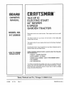
SEAl, S
OWNER'S
MANUAL
MODEL NO.
917.255930
®
Caution:
Read and follow
all Safety Rules
and lnstruchons
Before Operating
This Equipment
, Assembly
o Operation
• Maintenance
o Service and Adjustment
• Repair Parts
Sears, Roebuck and Co., Chicago, IL 60684 U.S.A.
SAFETY RULES
REPAIRS.
aNPORTANT
SAFETY STANDARDS REQUIRE OPERATOR PRESENCE CONTROLS TO MINIMIZETHE RISKOF INJURY. YOUR UNIT IS EQUIPPED WITH SUCH
CONTROLS° DO NOT ATTEMPT TO DEFEAT THE FUNCTION OFTHE OPERATOR PRESENCE CONTROLS UNDER ANY CIRCUMSTANCES.
TRAINING:
,
•
•
•
•
Know the controls and how to stop quickly, Read this owner's
manual and instructions furnished with attachments.
Do not allow children to operate the machine. Do not atiow
adu}ts to operate it without proper instruction.
Do not carry passengers Do not mow when children and
others are around.
Do not attempt to operate your vehicle or mower when not in
the driver's seat..
Always get on or off your vehicle from the operator's left hand
side,.
The vehicle and attachments should be stopped and inspected for damage after striking a foreign object, and the
damage should be repaired before restarting and operating
the equipment
.
•
•
.
•
•
PREPARATION:
•
,
Always wear substantial footwear° Do not wear loose fitting
clothing that could get caught in moving parts_
Clear the work area of objects (wire, rocks, etc..) which might
be picked up and thrown
Disengage all attachment clutches before attempting to start
the engine.
Handle gasoline with care - it is highly flammable.
Use approved gasoline containers
N ever re move the fu elcap of the fuel tank or add gaso]in e
to a running or hot engine or an engine that has not been
allowed to cool for several minutes after running_Never
fi]l tank indoors. Always clean up spilled gasoline..
Open doors if the engine is run in the garage - exhaust
fumes are dangerous. Do not run the engine indoors_
Do not operate the mower without the entire grass catcher,
on mowers so equipped, or the deflector shield in place.
•
•
•
•
OPERATION:
•
•
•
•
•
•
•
Keep your eyes and mind on your vehicle mower, and the
area being cuL Do not let other interests distract you..
Disengage power to attachments and stop the engine before
leaving the operator's position.
Disengage power to mower, stop the engine, and disconnect
spark plug wire(s) from spark plug(s) before cleaning, making
an adjustment, or repair. Be careful to avoid touching hot
muffler or engine components_
Disengage power to attachments when transporting or not in
use,
Take all possible precautions when leaving the vehicle unattende& Disengage the power take-off, lower the attachments, shift into neutral, set the parking brake, stop the
engine, and remove the key.
Do not stop or start suddenly when going uphill or downh!!l.
Mow up and down the face of slopes (not greater than t5 ),
never across the face.
Reduce speed on slopes and make turns gradually to prevent
tipping or loss of control. Exercise extreme caution when
changing direction on slopes,
While going up or down slopes, place gearshift control lever
in 1st gear position to negotiate the slope without stopping.
MAINTENANCE
•
•
•
•
•
•
i
LOOK FOR THIS SYMBOL
IT MEANS - ATTENTIONITI
ii
i
i.i
,11 i i i,i
iii
TO POINT
BECOME
,11,,,1111,1111,,
Never mow in wet or slippery grass, when traction is unsure,
or at a speed which could cause a skid.
Stay alert for holes in the terrain and other hidden hazards.
Keep away from drop-offs..
Do not drive too close to creeks, ditches, and public highways
Exercise special care when mowing around fixed objects in
order to prevent the blades from striking them= Never deliberately run vehicle or mower into or over any foreign objects.
Never si_ift gears until vehicle comes to a stop
Never place hands or feet under the mower, in discharge
chute, ot near any moving parts while vehicle or mower is
running. Always keep clear of discharge chute
Use care when pulling loads or using heavy equipment.
Use only approved drawbar hitch points
Limit loads to those you can safely control.
Do not turn sharply. Use care when backing.
Use counterweight or wh eel weights when suggested in
owner's manual.
Watch out for traffic when crossing or near roadways.
When using any attachments, never direct discharge of
material toward bystanders nor allow anyone near the veo
hicte while in operation
Except for adjustments, do not operate engine if air cleaner
or cover directly over carburetor air intake is removed,
Removal of such part could create a fire hazard
Do not change the engine governor settings or overspeed
the engine; severe damage or injury may result
When using the vehicle with mower, proceed as follows:
Mow only in daylight or in good artificial tighL
Shut the engine off when unclogging chute.
Check the bfade mounting bolts for proper tightness at
frequent intervals..
Disengage power to mower before backing up Do not mow
in reverse unless absolutely necessary and then only after
careful observation of the entire area behind the mower.
i
iiiiiiiii1,,
AND STORAGE
Keep the vehicle and attachments in good operating condition, and keep safety devices in place and working
Keep all nuts, bolts, and screws tight to be sure the equip.
ment is in safe working condition.
Never store the equipment with gasoline in the tank inside a
building where fumes may reach an open flame or spark.
Allow the engine to cool before storing in any enclosure.
To reduce fire hazard, keep the engine free of grass, leaves
or excessive grease. Do not clean product while engine is
running.
Do not operate without a muffler, or tamper with exhaust
system° Damaged mufflers or spark arresters could create a
fire hazard Inspect periodically and replace if necessary.
Under normal usage the grass catcher bag material is
subject to deterioration and weal It should be checked
frequently for bag replacement
Replacement bags should
be checked,to
ensure compliance
with the original
manufacturer s recommendations or specifications.
"
....................
i iii1,11,,i
OUT IMPORTANT
ALERTII!
YOUR
I
i:ujj I
SAFETY
PRECAUTIONS.
SAFETY IS INVOLVED.
ii iii
i1,1...............
PRODUCT
CONd_RATULATIONS
on your purchase of a Sears
Tractor, it has been designed, engineered and manufactured to give you the best possible dependability and
performance.
Should you experience any problem you cannot easily
remedy, please contact your nearest Sears Service
Center/Department
We have competent, well-trained
technicians and the proper tools to service or repair this
uniL
Please read and retain this manual, The instructions will
enable you to assemble and maintain your unit properly,
Always observe the "SAFETY RULESL
MODEL
NUMBER
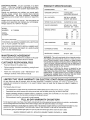
SPECIFICATIONS
HORSEPOWER:
18 0
GASOLINE CAPACITY:
3 5 GALLONS
UNLEADED REGULAR
OIL (3.0 PINTS)
SAE 30 (or 10W-30)
WINTER: SAE 5W-30
SPARK PLUG (GAP,030 IN):
CHAMPION RJ-19LM
VALVE CLEARANCE:
INTAKE 004 - ,006 IN
EXHAUST 007 - 009 IN
GROUND SPEED:
917,,255930
SERIAL
NUMBER
1st
2rid
3rd
Rev,
(MPH):
LO
HI
8
18
1.4
34
2,4
55
,9
21
DATE OF PURCHASE
THE MODELAND SERIAL NUMBERSWILL
QN A PLATE UNDER THE SEAT.
BE FOUND
YOU SHOULD RECORD BOTH SERIAL NUMBER AND
DATE QF PURCHASE AND KEEP iN A SAFE PLACE
--OR FUTURE REFERENCE,
TIRE PRESSURE:
FRONT:
REAR:
CHARGING
TRI CIRCUIT
SYSTEM:
BLADE BOLT TORQUE:
MAINTENANCE
30-35 FT. LBS
AGREEMENT
WARNING: This unit is equipped with an internal combustion engine and should not be used on or near any unimproved forest-covered, brush-covered or grass-covered
land unless the engine's exhaust system is equipped with
a spark arrester meeting applicable local or state laws (if
any), If a spark arrester is used it should be maintained in
effect ve working order by the operator,
A Sears Maintenance Agreement is available on this product, Contact your nearest Sears store for details,
CUSTOMER
14 PSi
10 PSI
RESPONSIBILITIES
•
Read and observe the safety rules,
•
Follow a regular schedule in maintaining, caring for and
using your unit,
•
Follow the instructions under "Maintenance"
"Storage" sections of this owner's manual
In the state of California the above is required by law
(_Section 4442 of the California Pubtic Resources Code),
Other states may have similar laws, Federal laws apply on
federal lands, A spark arrester for the muffler is available
through your nearest Sears Authorized Service Center
(See REPAIR PARTS section of this manual)°
and
,,,,i,,n,,,
LIMITED TWO YEAR WARRANTY
,, ,,,m,,
ON ELECTRIC
, ,
i
,,,, ,,,,,,,,,,,,, ,,,
START RIDING EQUIPMENT
For two years from date of purchase, when this riding equipment is maintained, lubricated, and tuned up according to the
operating and maintenance instructions in the owner's manual, Sears witl repair free of charge any defect in material or
workmanship
This Warranty does not cover:
Tire replacement or repair caused by punctures from outside objects (such as nails, thorns, stumps, or glass)
Expendable items which become worn during normal use. such as blades, spark plug, air cleaners and belts
Repairs necessary because of operator abuse or negligence, includingbent crankshafts and the failure to maintain the
equipment according to the instructions contained in the owner's manuat
Riding equipment used for commercial or rental purposes
FULL 90 DAY WARRANTY
ON BATTERY
For 90 days from date of purchase, if any battery included with this riding equipment proves defective in material or workmanship
and our testing determines the battery will not hold a charge, Sears wilt replace the battery at no charge
WARRANTY SERVICE IS AVAILABLE BY CONTACTING THE NEAREST SEARS SERVICE CENTER/DEPARTMENT
UNITED STATES THIS WARRANTY APPLIES ONLY WHILE THIS PRODUCT IS IN USE IN THE UNITED STATES
This Warranty gives you specific legal rights, and you may also have other rights which vary from state to state
SEARS, ROEBUCK AND CO., D/731CR-W SEARS TOWER, CHICAGO, tL 60684
3
IN THE
,,,,,,,,,,,,,
i i
IIHI
II II
.
mL
U l
I,,, .................
U
OF CONTENTS
TABLE
.................
U,llll
..................................
..i
ill,
,
..........
,i
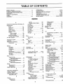
OPERATION ............................................................
MAINTENANCE .....................................................
SERVICE AND ADJUSTMENT .,.,'..........................
STO RAG E ...................................................................
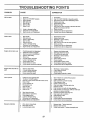
TROUBLE SHOOTING ...........................................
REPAIR PARTS-TRACTOR
...................................
SLOPE SHEET ............................................ BACK
SAFETY RULES ...........................................................
2
PRODUCT SPECIFICATIONS ....................................... 3
CUSTOMER RESPONSIBILITIES ................................. 3
WARRANTY .................................................................
3
TABLE OF CONTENTS .................................................
4
INDEX ...........................................................................
4
ASSEMBLY ................................................................
7-9
11-14
15-18
t 9-25
26
27-28
30-48
PAGE
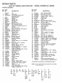
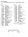
ENDEX
A
Adjustment,Attachrnent Lift Spring.
Adjustments:
Brake ......................................
Carburetor ..............................
Choke .......................................
Clutch Pulley ...........................
Gauge Wheels ........................
Mower':
Front-To-Back ....................
Side-To-Side ......................
Mower Drive Belt ......................
Throttle Control Cable .............
Air Filter', Engine ...........................
23
21
25
24
21
13
20
19
20
24
20
Air Screen, Engine ........................ 18
Assembly ..................................... 7-10
Attachment Lift Spring:
Adjustment .............................. 23
B
Battery:
Charging ..................................
8
Cleaning ................................. 17
Installation ............................... t0
Levels .................................. 8,17
Preperation ................................ 8
Starting with Weak Battery ...... 23
Storage .................................... 26
Terminals ............................... 17
Belt:
Motion Drive:
Removal/Replacement ....... 22
Mower' Blade Drive:
Removal/Replacement ....... 21
Mower Drive:
Removal/Replacement ....... 20
Blade:
Replacement ............................ 16
Sharpening ............................. 16
Brake Adjustment .......................... 2t
O
Carburetor, Adjustment ..................
Choke, Adjustment ........................
Controls, Tractor ............................
Cutting Height, Mower ...................
Gearshift Lever .........................
25
24
11
12
t0
Engine:
Adjustments:
Carburetor ........................... 25
Choke .................................. 24
Throttle Control Cable ......... 24
Air' Fitter ................................... 18
Air Screen ................................ 18
Cooling Fins ............................ 18
Oil Change .............................. 17
Oil Level ............................. t3,17
Oil Type ................................. t7
Preparation .............................. 13
Starting ..................................... 14
Storage .................................... 26
F
Filter:
Air Cleaner ..............................
Fuel .........................................
Fuel:
Storage .....................................
Type ......................................
Fuel Type ...............................
Fuse ..............................................
Headlights ...................................
Hood Removal ............................
Cutting Height ........................
Installation ..................................
Operation ................................
Removal ..................................
Mowing T ps .................
Muffler .................. ......................
Spark Arrester, ..........................
12
9
13
19
14
18
3
O
Oil:
18
18
Cold Weather Conditions ,_ 13,t7
Engine ....................................
17
Transaxle ................................ 16
Operating Mower .......................... 13
Operation ................................
! 1-14
P
26
14
13
23
Parking Brake .......................
11,12
Parts Bag .......................................
6
Product Specifications ................... 3
S
23
24
Leveling Mower Deck ........ 19_20
Lubrication Chart .................... 15
M
Maintenance ............................... 15-18
Air Filter, .................................. 18
Foam Pre-Cleaner .............. 18
Air Screen, Engine ................... 18
Battery ..................................... 17
Blade ........................................ 16
Cooling Fins, Engine ............... 18
Engine Oil ................................ 17
Fuel Filter ................................ I8
Lubrication Chart ..................... 15
Schedule ................................ 15
Spark Plugs ............................ 18
Tire Care ......................... 8,16,22
Tractor:
Transaxie Oil Level ............ 16
Mower:
Adjustment:
Front-To-Back ................. 20
Side-To-Side ................... t9
Blade Replacement ................. 16
Blade Sharpening .................... 16
Safety Rules .................................... 2
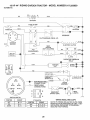
Schematic ....................................... 29
Seat ................................................
8
Service & Adjustments ............. 19-25
Attachment Lift Spring ............. 23
Clutch Pulley ............................ 21
Fuse ........................................ 23
Mower' Adjustment
Front-To-Back .................... 20
Side-To-Side ..................... 19
Motion Drive Belt:
Removal/Replacement ...... 22
Mower Blade Drive Belt:
Removal/Replacement ......
21
Mower Drive Belt:
Removal/Replacement ...... 20
Mower Removal ...................... 19
Tire Care .......................... 8,t 6,22
Slope Guide Sheet ........................ 5!
Spark Plugs .................................... 18
Specifications ..................................... 3
Starting the Engine ......................... 14
Steering Wheel ........................... 7,22
Stopping the Tractor ..................... 12
Storage .........................................
26
T
Throttle Control Cable:
Adjustment .............................. 24
Tires .......................................... 8,16,22
Troubleshooting ......................... 27-28
W
Wiring Schematic ............................ 2c_
ACCESSORIES
AN
ATTACHMENTS
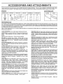
These accessories and attachments were available when the unit was purchased, They are also available at most Sears retail outlets,
catalog and service centers Most Sears stores can order these items for you when you provide the model number of your tractor,
ENGINE
SPARK PLUG
MAINTENANCE
MUFFLER
AIR FILTER
GAS CAN
ENGINE OIL
STABILIZER
BLADES
BELTS
PERFORMANCE
Sears offers a wide variety of attachments that fit your vehicleo Many of these are listed below with brief explanations of how they can help
you. This list was current at the time of publication; however, it may change in future years- more attachments may be added, changes may
be mad e in these attachments, or some may no longer be available or fit your model Contact your nearest Sears store for the accessories
and attachments
that are available for your unit.
Most of these attachments
attaching and detaching,
LAWN SWEEPERS
do not require additional hitches or conversion
let you collect grass clippings and leaves
LAWN VACS for powedul coI{ection of heavy grass clippings and
leaves. Wand attachment to pick up debris in hard-to-reach
places,
CARTS make hauling easy. Variety of sizes available.
ROLLER for smoother lawn surface.
36-inch wide, 18 inch
diameter water-tight drum holds upto 390 Ibs. of weighL Rounded
edges prevent harm to turf Adjustable scraper automatically
cleans drum,
SPREADER/SEEDERS
make seeding, fertilizing, and weed kilF
ing easy, Broadcast spreaders are also useful for granular deicers and sand.
CORING AERATOR takes small plugs out of soil to allow moisture and nutrients to reach grass roots
36-inch swath, 24
hardened steel coring tips, 150 lb capacity weight tray.
AERATOR promotes deep root growth for a healthy iawn, Tapered 2,5" steel spikes mounted on 10-in, diameter discs puncture holes in soil at close intervals to let moisture soak in. Steel
weight tray for increased penetration,
DETHATCH ER loosens soil and flips thatch and matted leaves to
lawn surface for easypickupo Twentyspringt[neteeth.
Usefulto
prepare bare areas for seeding
Available for front or rear
mounting,
SPRAYERS use 12-volt DC electric motor that connects to the
tractor battery or other !2-volt source.
Includes booms for
automatic spraying when pulling, and hand held wand for spot
spraying. Wand has adjustable spray pattern
For applying
herbicides, insecticides, fungicides, and liquid fertilizers.
SNOWTHROWER has 40-inch swath. Drum-type auger handles
powdery and wet/heavy snow, Mounts easily with simple pin
arrangement, Discharge chute adjusts from tractor seat, 6-inch
diamster spout discharges snow 10 to 50 feet, Lift controlled at
tractor seat, (Use with chains, wheel weights, or rear drawbar
weightr)
TIRE CHAINS are heavy duty; closeiy spaced extra-large cross
links give smooth ride, outstanding traction.
WHEEL WEIGHTS for rear wheels provide needed traction for
snow removal or dozing heavy materials
(55 Ibs, each.)
kits (those that do are indicated) and are designed for easy
TRACTOR CAB has heavy duty vinyl fabric over tubular steel
frame, ABS plastic top; clear plastic windshield offers 360 degree
visibility. Hinged metal doors with catch. Keeps operator warm
and dry Remove vinyl and windshields for use as sun protector
in summer.
Optional accessories for tractor cab: tinted/tempered solid
safety glass windshield with hand operated wiper; 12-volt amber
caution light for mounting on cab top
TRACTOR COVER protects tractor from weather,
Made of
Evolution 3 fabric (water-repellent, extremely breathable, {ight
weight, soft, non-abrasive, pliable in all temperatures, durable,
stain/tear/puncture resistant, will not shrink or stretch),
TILLER has 8hp engine to prepare seed beds, cultivate and
compost garden residue, Chain-drive transmission, Six 11-inch
diameter one piece heat-treated steel tines, Tills 30-inch path,
(Requires sleeve hitch.)
DOZER BLADE removes snow; grades dirt, sand and gravel, 48
inches wide, 17 inches high, clears 44-inch path when angled,
Master lift control lever for operator ease. Spring trip for snow
removal on uneven pavement; built-in float for blade to follow
ground contour. Reversible, replaceable scraper bar_ (Use with
tire chains, wheel weights or rear drawbar weight.)
R EAR BLADE is 42-inches wide and operated from driver's seat,
Reversible steel blade can be angled at 30 degrees for grading.
Reverses for snow plowing. (Requires sleeve hitch,)
SLEEVE
seeding,
sweeps.
Optional
openings
CULTIVATOR is 43-inches wide, Prepares ground for
helps weed control, Steef frame holds 5 adjustable
Adjusts vertically, horizontally. (Requires sleeve hitch )
accessory for cultivator: steel furrow opener for wider
for potatoes, corn, and other deep-seeded crops.
PLOW turns soil 6 inches deep, cuts 10-inch furrow Crank
adjustment controls depth, 3-position yoke sets width. Heavy
steel landslide for straight furrowing, (Requires sleeve hitch.)
DISC HARROW has 2 gangs of 4 steei blades that angle from 10
to 20 degrees, 40-inches wide
Can hook 2 units in tandem
(Requires sleeve hitch,)
WEIGHT BRACKET for drawbar for snow removal applications.
Can be mounted on front oftractor for plowing applications, Uses
(i) 55 lb. weight.
SLEEVE HITCH for use with master lift system,
couples/uncouples.
Single pin
.........................................
i
IL
rllll,
.........................................
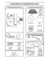
CONTSNT$ OF HARDWARE PACK
.........................
ii,,,u,
n n,,i......
H,
i
Parts Bag contents
= Hn,n,=
i,,,,,,1,,
,
uu,
1,1,111,,,,
nu,,,,,,,,
n,,u
, i
shown full size
m,,,
H,,,
,,, .....
Parts packed separately
=,,m .............
n,=
,,,,,,
,,nu,n, =
in carton
....
Seat
Battery acid
(1) Shoulder Bolt 5/16-18
Steering Wheel
(1) Knob
Battery
(1) Washer 17/32 x 1-3/16 x 12 Ga,
0wner_s
Parts Bag
Parts bag contents
i,,H
not shown full size
i,li
i
,,,,ml
(2) Keys
(4) Retainer Springs
(4) Washers
(2) Hex Bolts 1/4 - 20 x 3/4
,u
Manual
11/32x 1
(2) Battery Carriage Bolts 1/4.20 x 7-1/2
@
(2) Hex Nuts t/4 - 20
®
Terminal Guard
Steering Wheel Insert
(2) Washers 9/32 x 5/8 x 16 Ga. (2) Lock Washers 1/4
1:
i
(2) Wing Nuts 1/4 - 20
15 ° Slope Sheet
6
Battery Caps
and Instructions
ASSEMBLY
...............
:':Jl_,,,rui.u,L,_
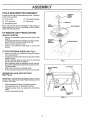
TOOLS
,
REQUIRED
i
. ...................................
FOR ASSEMBLY
STEERING
WHEEL
INSERT
A socket wrench set will make assembly easier. Standard
wrench sizes are listed
(1) 9/16" wrench
(1) Tire pressure gauge
(2) 7/16" wrenches
(1) Utility knife
HEX BOLT
(1) Adjustable wrench
LOCK
WASHER_
When right and left hand is mentioned in this manual, it
means when you are in the operating position (seated
behind the steering wheel).
TO REMOVE
UNPACK
•
•
.
•
•
•
•
•
•
•
FLAT WASHER
UNIT FROM CARTON
CARTON
Remove all accessible loose parts from carton (See
page 6),
Cut along dotted lines on the carton, from top to bottom,
al! four corners of carton and lay panels flat.
Remove mower deck from skid°
Check for any additional loose parts or cartons and
remove.
ATTACH
(_
STEERING
WHEEL
STEERING
WHEEL
_
ADAPTER
STEERINGSHAFT
(See Fig. 1)
Remove hex bolt, lock washer and large flat washer
from steering shaft.
Position front wheels of the tractor so they are pointing
straight forward,
Position steering wheel so cross bars are horizontal
(left to right) and slide onto adapter.
Secure steering wheel to steering shaft with hex bolt,
lock washer and large fl at washer previously removed.
Tighten securely
Snap insert into center of steering wheel.
Remove protective plastic from tractor hood and grill,
///
FIG. 1
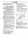
UFT LEVER
CLUTCH/BRAKE
PEDAL
=
BEFORE ROLLING
(See Fig. 2)
UNIT OFF SKID
IMPORTANT;
CHECK FOR AND REMOVE ANY STAPLES
IN SKID THAT MAY PUNCTURE TIRES WHERE UNIT IS
TO ROLL OFF SKID.
.
•
•
.
l
Raise attachment lift lever to its highest position
Place gearshift lever in "NEUTRAL" position
Release parking brake by depressing clutch/brake
pedal,
Roll unit backwards off skid,
GEARSHIFT
LEVER
FIG. 2
7
ASSEMBLY
..................
i i i
i,i
HOW TO SET UP YOUR TRACTOR
INSTALL
PREPARE
Adjust seat before tightening adjustment knob=
BATTERY
(See Fig. 3)
•
Remove cardboard packing on seat pan,
CAUTION: Wear eye and face shield°
•
Place seat on pan and assemble shoulder knob.
Wash hands or clothing immediately if
accidentally in contact with battery acid.
,
Assemble adjustment knob, Iockwasher and flat washer
loosely. Do not tighten.
Do not smoke. Fumes from charged
battery acid are explosive.
Read the instructions included with the
battery vent caps. Alwayswear gloves,
clothing and goggles to protect your
hands, skin and eyes.
,
Tighten shoulder bolt securely.
•
Lower seat into operating position and sit on seat.
•
Slide seat until a comfortable position is reached which
allows you to press clutch/brake pedal all the way
down.
•
Get off seat without moving its adjusted position.
°
Raise seat and tighten adjustment knob securely.
"our unit has a battery charging system which is sufficient
for normal use. However, periodic charging of the battery
with an automotive charger will extend its life.
•
See instructions packed with vent caps in parts bag.
•
Fill battery with acid. Fill each cell until it reaches the
bottom of the vent wells. Do not overfill.
•
Allow battery to stand and settle for at least thirty
minutes. After standing, check the level of acid. If
below the vent wells, add more acid until the correct
level is reached.
SEAT
SEAT PAN
SHOULDER
BOLT
While battery is standing (after adding acid) and later, while
battery is being charged, continue with assembly of unit.
IMPORTANT':
TO MAXIMIZE THE LIFE OF YOUR
BATTERY, IT IS NECESSARY THAT THE BATTERY BE
CHARGED BEFORE USE.
FAILURE TO CHARGE
BATTERY CAN RESULT IN A SHORTENED BATTERY
LIFE
•
Charge battery at a rate of 6 amperes for 1 hour. Use
a 12 volt battery charger Observe all safety precautions required for battery charging
•
Check the acid level after the battery is charged, If the
acid has fallen below the correct level, add distilled or
iron free water,
•
Install the vent caps to cover the vent wells. Wash the
top of the battery with water to remove any acid, then
wipe dry.
•
Check battery case for leakage to make sure that no
damage has occurred in handling.
•
Dispose of excess battery acid. Neutralize acid for
disposal by adding it to four inches of water in a five
gallon plastic container. Stir with a wooden or plastic
paddle while adding baking soda until the addition of
more soda causes no more foaming,
•
SEAT (See Fig. 4)
Follow instructions on how to install battery.
.VENT CAP
CUT AWAY VIEW
VENT WELL
BATTERY
CELLACID
LEVEL
FIG. 3
FLAT WASHER
ADJUSTMENT
KNOB
FIG. 4
CHECK
TIRE PRESSURE
The tires on your unit were overinflated at the factory for
shipping purposes, Correct tire pressure is important for
best cutting performance.
•
Reduce tire pressure to PSI shown in "PRODUCT
SPECIFICATIONS" on page 3 of this manual,
CHECK BRAKE SYSTEM
After you learn how to operate your tractor, check to see
that the brake is properly adjusted. See 'TO ADJUST
BRAKE' in the Service and Adjustments section of this
manual.
ASSEMBLY
11
,..............................
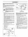
INSTALL
MOWER
AND DRIVE
111,1,
•
......
BELT
GAUGE
WHEEL
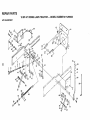
Your unit has been shipped with the front mower suspension braket banded to the frame Remove bands and pivot
bracket downward.
MOWER INSTALLATION
11.1 =
BAR
(See Figs. 5, 6, 7 and 8)
Remove banding from suspension arms and gauge
wheels Set gauge wheels aside for later assembly.
•
Slide mower under tractor with discharge guard to right
side of tractor.
•
Slide front suspension brackets into mower brackets.
Retain with release pins Turn depth adjustment knob
counterclockwise until it stops Lower mower linkage
with attachment lift lever.
•
Slide studs through lift links on both sides of tractor_
Retain with washers and retainer springs.
•
Place the suspension arms on brackets on both sides
of frame Retain with washers and retainer springs.
•
_i
GAUGE
__,,,_
_
I_---'-'-__
ETAINER
-)
WHEEL_
FIG. 7
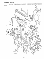
DRIVE BELT INSTALLATION
(See Figs. 8 and 9)
•
Remove hood and grill (See "TO REMOVE HOOD
AND GRILL ASSEMBLY" in the Service and Adjustments sections of this manual),
Place suspension arms in rear suspension brackets
Retain with release pins
•
•
•
Turn depth adjustment knob clockwise to remove slack
from mower suspension
Roll mower drive beft over primary mandrel
Roll mower drive belt forward over front mower suspension bracket,
•
°
Insert gauge wheel bar into bracket, Retain with clevis
pins and retainer springs.
Place mower drive belt over clutch pulley on engine
and under idler pulley and tension pulley,
•
Replace hood and grilFassembly
DEPTH
KNOB
SUSPENSION
ARM
NOTE: Pull tension pulley lever forward for belt clearance,
Make sure narrow "V" side of belt is engaged with each
pulley, and push tension pulley lever back to opearting
)osition.
ADJUSTMENT
BELT
\
MOTION
FRONT
S1ON
BRACKET
_ELEASE
PIN
FIG. 8
FIG. 5
CLUTCH
pULLEY _
RETAINER
SPRING
\Vo I_ !o I
l
_/'--_
-_f
_\_l
MOWER
DRIVE
_
//
.t, 2W" 1 ,0 ER
SUSPENSION
"__L_
_r--.=_F-_\X_
"
_--_
TENSION
WASHER __..._
RETAINER
_
SPRING--,.
._
_
LIFT LINK
__
-
-_-'_"
__l
PUL,
STUD
PULLEY
__
tL_'--
\
I
FIG. 9
CHECK
FIG, 6
9
DECK
LEVELNESS
For best cutting results, mower housing should be properly
leveled.
See "TO LEVEL MOWER HOUSING" in the
Service and Adjustments section of his manual,
CHECK
FOR PROPER
POSITION
OF ALL
BELTS
See the figures that are shown for replacing motion, mower
drive, and mower blade drive belts in the Service and
Adjustments section of this manual. Verify that the belts are
routed correctly
INSTALL
BATTERY
(See Figs.
ACCESS
10 &11)
BATTERY
BOLT
BATI'ERY
TRAY
CAUTION: Do not short battery terminals, Before installing battery, remove
metal bracelets, wristwatch bands,
rings, etc.
KEY HOLE
BATTERY
{AIN TUBE
FIG. 11
Positive terminal must be connected
first to prevent sparking from acciden,.
tal grounding.
,/CHECKLIST
,
Raise hood.
,
Make sure d rain tube is fastened to d rain hole in battery
tray and battery tray is positioned in hole of battery
support.
•
Place battery in plastic tray, battery terminals to front of
tractor.
PLEASE REVIEW THE FOLLOWING
#"
All assembly instructions have been completed.
,
First connect RED battery cable to positive (+) battery
terminal with hex bolt, flat washer, lock washer and hex
nut as shown. Tighten securely.
v"
No remaining loose parts in carton.
,/
Battery is properly prepared and charged.
hour at 6 amps).
BEFORE YOU OPERATE AND ENJOY YOUR NEW
TRACTOR, WE WISH TO ASSURE THAT YOU RECEIVE
THE BEST PERFORMANCE AND SA TISFACTION FROM
THIS QUALITY PRODUCT.
CHECKLIST:
(Minimum 1
°
Connect BLACK grounding cable to negative (-) battery
terminal with remaining hex bolt, flatwasher, lock washer
and hex nut. Tighten securely.
,/
•
Slide the two battery bolts through the terminal guard
and start the wing nuts onto the threads.
All tires are properly inflated. (For shipping purposes,
the tires were over-inflated at the factory).
v'
•
Position terminal guard over the battery as shown, lower
bolts into key holes and slide square shafts of bolts into
slots of key holes°
v"
•
Tighten wing nuts by hand making sure battery bolts
remain in slots of the key holes in the battery support.
Be sure terminal access doors are closed.
Be sure mower deck is properly leveled side-to-side/
front-to-rear for best cutting results. (Tires must be
properly inflated for leveling).
Check mower and drive belts. Be sure they are routed
properly around pulleys and inside all belt keeper&
•
v_ Seat is adjusted comfortably and tightened securely
,/
WHILE LEARNING HOW TO USE YOUR LAWN RIDER,
PAY EXTRA ATTENTION TO THE FOLLOWING IMPORTANT ITEMS:
Use terminal access doors for:
•
Inspection for secure connections (to tighten hardware).
,
Inspection for corrosion.
•
Testing battery.
•
Jumping (if required)°
•
Periodic charging.
HEX NUT
POSITIVE
....
"
CABLE
FLAT
HEX
BOLT
FIG. 10
Check wiring See that al! connections are still secure
and wires are properly clamped.
10
V'
Engine oil is at proper level
4'
Fuel tank is filled with fresh, clean, regular unleaded
gasoline
,/
Become familiar with all controls-their location and
function. Operate them before you start the engine.
v"
Be sure brake system is in safe operating condition.
..............................
== ,=
OPERATION
KNOW YOUR LAWN RIDER
READ THIS OWNER'S MANUALAND
SAFETY
RULES
BEFORE
OPERATING
YOUR LAWN
RIDER.
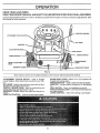
Compare the illustrations with your Tractor to familiarize yourself with the location of various controls and adjustments, Save
this manua! for future reference
THROTTLECONTROL
ATTACHMENT
CLUTCH
LIFT LEVER
AMMETER
CLUTCH/BRAKE PEDAL,_,_
LIGHT SWITCH
IGNITION SWITCH
CHOKECONTROL
PARKING
KNOBHEIGHT
ADJUSTMENT
GEARSHIFT
/
LEVER
BRAKE
LEVER
RANGE SHIFT LEVER
FIG. 12
Sears tractors conform to the safety standards of the American National Standards Institute.
ATTACHMENT
CLUTCH SWITCH - Used to engage
mower blades or other attachments mounted to your tractor.
LIFT LEVER - Used to raise and lower mower deck or other
attachments mounted to your tractor
CLUTCH / BRAKE PEDAL: Used for declutching and
braking the tractor and starting the engine.
GEARSHIFT LEVER: Selects the speed and direction of
tractor.
THROTTLE CONTROL - Used to control engine speed,
RANGE SHIFT LEVER - Allows "H!" or "LO" speed for all
forward and reverse gears°
IGNITION SWITCH - Used to start and stop the engine.
AMMETER - Indicates battery charging (+) or discharging
LIGHT SWITCH - Turns the headlights on and off.
PARKING BRAKE LEVER - Locks clutch/brake pedal into
the brake position,
CHOKE CONTROL - Used when starting a cold engine,
11
,,ui
i
i,
i,i1,
i1,,,,,
,,t
OPERATmON
,,
H,,,
li,,!,u,
,
i,i
li, ,,
i
Nil,,
, i,
L,,,,m,
,, N,,,
The operation of any tractor can result in foreign objects thrown into the eyes, which can result
in severe eye damage° Always wear safety glasses or eye shields before starting your tractor
and while moving, We recommend Wide Vision Safety Mask for over the spectacles or standard
safety glasses.
•
HOW TO USE YOUR TRACTOR
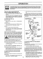
TO SET PARKING
BRAKE
(See Fig. 13)
.
Depress clutch/brake pedal into futl "BRAKE" position
and hold
•
Place parking brake lever in "ENGAGED" postion and
re_ease pressurefrom clutch/brake pedal Pedal should
remain in "BRAKE" position. Make sure parking brake
wilt hold vehicle secure,
STOPPING
Move gearshift
tion.
and range shift levers to desired
posi-
•
Slowly release clutch/brake
pedal to start movement.
iMPORTANT:
BRING TRACTOR TO A COMPLETE STOP
BEFORE SHIFTING
OR CHANGING
GEARS.
FAILURE
TO DO SO WfLL SHORTEN THE USEFUL LiFE OF YOUR
TRANSAXLE
"DRIVE"
POSITION
CLUTCH/BRAKE
PEDAL
"BRAKE" POSITION
(See Fig. 13)
MOWER BLADES •
Move attachment
position
GROUND DRIVE •
clutch switch to "DISENGAGED"
ATTACHMENT
,
Depress clutch/brake pedal into full "BRAKE" position
_
"_
CLUTCH SWITCH
/
•
Move gearshift lever to "NEUTRAL" position.
ENGINE -
_
•
Move Throttle Control to "SLOW"position
•
Turn ignition key to 'OFF" position and remove key.
Always remove key when leaving vehicie to prevent
unauthorized use
•
CHOKE
__
CONTROL
__THROTTLE
__
_
-/
_'CONTROL
Never use choke to stop engine.
NOTE: Under certain conditions when unit is standing idle
with the engine running, hot engine exhaust gasses may
cause "browning" of grass To eliminate this possibility,
always stop engTne when stopping unit on grass areas.
,
ll,lIHH
_
I
,NI,l,
I ,
I'
ll,ll,
•"" /
/
/
GEARSHIFT
LEVER
described
above, before leaving
the
CAUTION:s position;
operator
Always stop
to empty
unit completely,
grass catcher,
as
etc.
,LIL,
, ill,ill
TO USE CHOKE CONTROL
IHHI
,
II IHI 'l,'
..........
To engage choke control, pull knob out
knob into disengage.
TO USE THROTTLE
CONTROL
_'-_ e
_"_
y
PARKING BRAKE
DISENGAGED"
POSITION
FIG. 13
(See Fig. 13)
Use choke control whenever you are starting a cold engine.
Do not use to start a warm engine
•
\
._/
-'_
RANGE._
SHIFT
LEVER
TO ADJUST
MOWER
CUTTING
HEIGHT
(See Fig, 13)
Slowly push
The cutting height is controlled by turning the height adjustment knob in desired direction
(See Fig. 13)
•
Turn knob clockwise to raise cutting height
Always operate engine at full throttle.
•
Turn knob counterclockwise
•
Operating engine at less than full throttle reduces the
battery charging rate and the engine cooling air flow.
,
Full throttle offers the best mower performance,
The cutting height range is approximately 1-1/4" to 3-3/4".
The heights are measured from the ground to the blade tip
with the engine not running, These heights are approx_o
mate and may vary depending upon soil conditions, height
of grass and types of grass being mowed.
TO MOVE FORWARD
AND BACKWARD
(See Fig. 13)
•
The average lawn should be cut approximately 2-t/2
inches during the cool season and over3 inches during
hot months° For healthier and better looking lawns,
mow often and after moderate growth°
•
For best cutting performance, grass over 6 inches in
height should be mowed twice
Make the first cut
relatively high; the second to desired height
The direction and speed of movement is controlled by the
gearshift lever
•
Start tractor with clutch/brake pedal depressed and
gearshift lever in "NEUTRAL" position
12
to lower cutting height
,I,,H =
...........................
OPERATmON
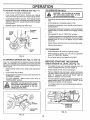
TO ADJUST
GAUGE
WHEELS
TO OPERATE
(See Fig. 14 )
ON HILLS
=ll=lHH=,
•
,
Adjust mower to desired cutting height,
Lower mower with lift control. Remove rear retainer
spring and clevis pin which secure each gauge wheel
•
Lower gauge wheels to ground_ Raise gauge wheels
slightly to align holes in bracket and gauge whee_ bar
and insert clevis pins. Gauge wheels should be slightly
off the ground.
•
Choose the slowest speed before starting up or down
hills.
•
Avoid stopping or changing speed on hills.
Replace retainer springs into clevis pins.
•
If slowing is necessary, move throttle control lever to
slower position°
•
If stopping is absolutely necessary, push clutch/brake
pedal quickly to brake position and engage parking
brake,
•
Move gearshift
•
To restart movement, move gearshift lever to 1st gear
and range shift lever to"LO" position, Besureyouhave
allowed room for unit to roll slightiy as you restart
movement
•
Slowly release parking brake and clutch/brake pedal.
•
Make all turns slowly.
o
_
BRACKET
(See Figs.
!
lever to "NEUTRAL" position°
TO TRANSPORT
.
Raise attachment lift control to highest position
•
When pushing or towing your unit, be sure gearshift
lever is in "NEUTRAL" position.
•
Do not push unit at more than five (5) MPH.
FIG. 14
MOWER
Do not drive up or down
hills with slopes greater than 15 0 and
do n,,o,!,,,d,rive
ac,,r,o,ssany slope.
I
CLEVIS
PINS
TO OPERATE
CAUTION;
| _
RETAINER
--SPRING
GAUGE
WHEEt,
BAR
GAUGE
WHEEL
_,
12 and 13)
BEFORE
Your unit is equipped with an operator presence sensing
switch, Any attempt by the operator to leave the seat with
the engine running and the mower clutch engaged will shut
off the engine.
CHECK
STARTING
ENGINE
THE ENGINE
OIL LEVEL
(See Fig. 16)
•
Select desired height of cut, using height adjustment
knob,
The engine in your unit has been shipped, from the
factory, already filled with summer weight oil
•
Check engine oil with unit on fevet ground_
.
Lower mower with lift lever°
•
•
Engage mower by slowly moving mower clutch lever to
"ENGAGED" position
Remove dipstick and wipe clean, replace and screw
cap tight, wait for a few seconds, remove and read oil
level. If necessary, add oil until "FULL" mark on
dipstick is reached. Do not overfill.
•
TO STOP MOWER - Move mower clutch lever to
"DISENGAGED" position
•
For cold weather operation you should change oil for
easier starting (see "OIL VISCOSITY CHART" in the
Maintenance section of this manual).
•
To change engine oil, see the Maintenance section in
this manual
•
CAUTION: Do not operate the mower
without either the entire grass catcher,
on mowers so equipped, or the discharge guard In place.
__
"_"
RUNNER
R.H,
_'_"_-_-__
ENGINE OIL
FILLER CAP
& DIPSTICK
DISCHARGE
GUARD
FIG. 16
FIG. 15
13
ADD GASOLINE
MOWING
•
•
Tire chains cannot be used when the mower housing
is attached to unit.
•
Mower should be properly leveled for best mowing
performance. See "TO LEVEL MOWER HOUSING"
in the Service and Adjustments
section of this
manual°
•
Use the runner on the right hand side of mower as
a guide. The blade cuts apprximately an inch outside the runner (See Fig,. 15).
The left hand side of mower shouid be used for trimming.
Fill fuei tank
Use fresh, clean, regutar unleaded
gasoline. (Useof leaded gasolinewitl increasecarbon
and lead oxide deposits and reduce valve life),
IMPORTANT; WHEN OPERATING IN TEMPERATURES
BELOW 32_F(0°C), USE FRESH, CLEAN WINTER GRADE
GASOLINE TO HELP INSURE GOOD COLD WEATHER
STARTING.
WARNING:
Experience indicates that alcohol blended
fuels (called gasohol or using ethanol or methanol) can
attract moisture which leads to separation and formation of
acids during storage, Acidic gas can damage the fuei
system of an engine while in storage. To avoid engine
problems, the fuel system should be emptied before storage of 30 days or longer. Drain the gas tank, start the
engine and let it run until the fuel lines and carburetor are
empty, Use fresh fuel next season. See Storage Instructions for additional inforrnation_
Never use engine or
carburetor cleaner products in the fuel tank or permanent
damage may occur.
TO START
ENGINE
•
(See Fig,13)
When starting engine for the first time or if engine has
run out of fuel, it wili take extra cranking time to move
fuel from the tank to the engine_
•
Depress the clutch/brake
brake°
.
Place gearshift lever in "NEUTRAL"
•
Move attachment clutch to "DISENGAGED"
.
Pull choke control out to "CHOKE" position for cold
engine start.
For warm engine start do not use
choke control
.
Move throttle control to midway between "FAST" and
"SLOW" positions.
•
°
Drive so that clippings are discharged onto the area
that has been cut. Have the cut area to the right of
the machine, This will result in a more even distribution of clippings and more uniform cutting.
•
When mowing large areas, start by turning to the
right so that clippings wilt discharge away from
shrubs, fences, driveways, etc. After one or two
rounds, mow in the opposite direction making left
hand turns until finished (See Fig° 17).
.
if grass is extremely tall, it should be mowed twice
to reduce load and possible fire hazard from dried
clippings. Make first cut relatively high; the second
to the desired height,.
.
Do not mow grass when it is wet
plug mower and leave undesirable
grass to dry before mowing.
•
Always operate engine at full throttle when mowing
to assure better mowing performance and proper
discharge of material. Regulate ground speed by
selecting a low enough gear to give the mower cutting performance as welt as the quality of cut desired.
•
When operating attachments, select a ground speed
that will suit the terrain and give best performance of
the attachment being used.
pedal and set the parking
position.
position.
TiPS
Turn ignition key clockwise to "START" position and
release key as soon as engine starts, Do not run
starter continuously for more than fifteen seconds
per minute. If engine does not start after several
attempts, move throttle control to "FAST" position,
wait a few minutes and try again.
.
When engine starts, slowly push choke control in,
•
Move throttle control to "FAST" position_
•
Al!ow engine to warm up for a few minutes before
engaging clutch/brake pedal or attachment clutch
switch.
FIG. 17
NOTE: If at a high altitude (above 3000 feet) or in cold
temperatures (below 32 F), the carburetor fuel mixture
may need to be adjusted for best engine performance.
See 'TO ADJUST CARBURETOR" in the Service and
Adjustments section of this manual
CAUTION:
Before driving the tractor,
install mower or remove front mower
suspension
bracket and suspension
arms.
14
Wet grass will
clumps. Allow
MAINTENANCE SCHEDULE
7___o_/"
/_/_-_._.O_
._'_.,_.#_._
.,_'__._:/£,_"SERVICE
FILLINDATES
AS YOU COMPLETE
REGU_R SERV!CE
Check Brake Operation
R
_,Gf
6/
Check Tire Pressure
6#4
6/
Check for Loose Fasteners
6##
Sharpen/Replace Mower
T
0
R
'
v
DATES
6/#4
6/4
Blades
Lubrication Chart
_O?'_
.
.
,
. 6/
,Check BatterY Level/Recharge ..........
Clean Battery and Terminals
6#4
6/
64#
,
,
,
6#4
6/
Check Transmission Cooling
Adjust Blade Belt(s) Tension
6/
Adjust Motion Drive Belt(s) Tension
Check Engine Oil Level
Change Engine Oil
E
N
G
I
j2
J2
Clean Air Filter
Clean Air Screen ....
Inspect Muffler/SparkArrester
6/
Replace Oil Filter (if equipped)
6/2
NE Cfean Engine Coolir],g Fins
Replace Spark Plug
v'6/
Replace Air Filter Paper Cartridge
Reptace Fuel Filter
I _ Change mere often when operating under a heavy load or In hlgh ambient
2 - Service more often when operating in dirty or dusty conditions
GENERAL
RECOMMENDATIONS
temperatures
3 - If equipped with oil filter, change eli every 50 hours
4 - Replace blades more often when mowing In sandy soil
LUBRICATION
The warranty on this vehicle does not cover items that
have been subjected to operator abuse or negligence. To
receive full value from the warranty, operator must maintain unit as instructed in this manual,
CHART
(_TIE RODBALLJOINTS
(,_)SPINDLEZERK------_/__
Some adjustments will need to be made periodically to
properly maintain your unit.
_--
(_ FRONTWHEEL _'__,:-_'::_:L;_"
SPINDLEZERK(_)
FRONTWHEEL (_)
All adjustments in the Service and Adjustments section of
this manual should be checked at least once each season,
•
@ STEERING
SECTOR GEAR
PLATE
Once a year you should replace the spark plug, clean
or replace air filter, and check blades and belts for
wear, A new spark plug and dean air fiiter assure
proper air4uef mixture and help your engine run better
and last longer.
BEFORE
EACH USE
•
Check engine oil level.
•
Check brake operation,
•
•
Check tire pressure.
Check for loose fasteners.
IMPORTANT:
DO NOT OIL OR GREASE THE PIVOT POENTS
WHICH HAVE SPECIAL NYLON BEARING&
VISCOUS LUBRICANTS WILL ATTRACT DUST AND DIRT THAT WILL SHORTEN
THE LIFE OF THE SELF-LUBRICATING
BEARINGS.
IF YOU
FEEL THEY MUST BE LUBRICATED,
USE ONLY A DRY, POWDERED GRAPHITE TYPE LUBRICANT
SPARINGLY
ENGINE (_)
(_) CHECIqADD .,.
TRANSAXLE
FLUID
(_) SAE 30 MOTOR OIL API - SG
(_) GENERAL PURPOSE
GREASE
(_) REFER TO ENGINE MAINTENANCE
SPRAY SILICONE LUBRICANT
15
SECTION
(MOVE BOOTS TO LUBRICATE)
ii==
,, =,=,
i H=
NTENANCF=
, 11,
====,,,=l
==Ni=
_--_--m
TRACTOR
TO SHARPEN
Always observe safety rules when performing any maintenance,
Care should be taken to keep the blade balanced
An
unbalanced blade will cause excessive vibration and eventual damage to mower and engine.
BRAKE OPERATION
.
The blade can be sharpened with a file or on a gdnding
wheel Do not attempt to sharpen while on the mower,
•
To check blade balance, drive a nailinto a beam or wall,
Leave about one inch of the straight nail exposed.
Place center hole of blade over the head of the nail, If
blade is balanced, it should remain in a horizontal
position If either end of the blade moves downward,
sharpen the heavy end until the blade is balanced,
If unit requires more than six (6) feet stopping distance at
high s_eed in highest gear, than brake must be adjusted
(See TO ADJUST BRAKE in Service and Adjustments
section of this manual).
TIRES
.
Maintain proper airpressure in all tires (See "PRODUCT SPECIFICATIONS" on page 3 of this manual),
*
Keep tires free of gasoline, oiI, or insect control chemicals which can harm rubber.
,
Avoid stumps, stones, deep ruts, sharp objects and
other hazards that may cause tire damage.
BLADE
:
(See Fig. 19)
CENTER
HOLE
. I
BLADE
O
BLADE CARE
For best results mower blades must be kept sharp_ The
blades can be sharpened with a file or on agrinding wheel.
We suggest they be sharpened or replacedafter every 25
hours of mowing Check blades more often if mowing in
sandy conditions,
•
Do not attempt to sharpen blades while they are on the
mower_
•
CHECK TRANSAXLE
(See Fig. 20)
Replace bent or damaged blades,
BLADE REMOVAL
Raise mower to highest position to allow access to
blades.
.
Remove hex bolt, lock washer and fiat washer securing
blade.
•
Install new or resharpened blade with trailing edge up
towards deck as shown_
OIL LEVEL
•
.
Block up rear axle securely or use a tractor jack
Remove left rear wheel by removing hub bolts.
.
Remove filler plug from transaxle, OiI level must be
even with plug threads. If necessary, fill with SAE 30
oil API-SG, Replace filler plug
•
Reassemble wheel to hub,
(See Fig. 18)
•
o
FIG. 19
TRANSAXLE
FILLER PLUG
O
Reassemble hex bolt, lock washer and flat washer in
exact order as shown_
o
,
Tighten bolt securely (30-35 Ft, Lbs. torque).
IMPORTANT: BLADE BOLT IS GRADE 5 HEATTREATED.
BLADE
MANDREL
"ASSEMBLY
FIG, 20
WASHER
LOCK WASHER
©
HEX BOLT
S)*
*A GRADE 5 HEAT TREATED BOLT
CAN BE IDENTIFIED BYTHREE
LINES ON THE BOLTHEAD AS
SHOWN AT LEFT,
FIG. 18
16
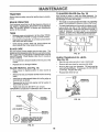
BATTERY
TO CHANGE ENGINE OIL (See Figs. 22, 23 and 24)
Determine temperature range expected before oil change°
All oil must meet API service classification SG,
• Be sure vehicle is on level surface,,
(See Fig. 21)
Your unit has a battery charging system which is sufficient
for normal use. However, periodic charging of the battery
with an automotive charger will extend it's life,
•
•
•
•
Acid solution level in each battery cell should be even
with bottoms ofventwells. Add only distilled or iron free
water if necessary Do not overfill
• Oil will drain more freely when warm,
Keep battery and terminals clean.
Keep battery bolts tight.
Keep vent caps tight and small vent holes in caps open°
Recharge at 6 amperes for 1 hour,,
• Remove oil fill dipstick,. Be careful not to allow dirt to
enter the engine when changing oil.
• Catch oil in a suitable container.
CUT AWAY VIEW
j
ENT CAP
VENT
BATTERY
CELL ACID
LEVEL
FILLER CAP &
DIPSTICK
FIG. 21
FIG. 22
TO CLEAN BATTERY AND TERMINALS -
• Remove drain plug_
Corrosion and dirt on the battery and terminals can cause
the battery to "leak" power.
•
Remove terminal guard,
.
Disconnect BLACK battery cable first then RED battery cable and remove battery from tractor.
Wash battery with solution of four tablespoons of
bakingsodatoone
gallon ofwater, Be careful nottoget
the soda solution into the cells.
•
•
•
Rinse the battery with plain water and dry.
Clean terminals and battery cable ends with wire brush
until bright,
Coat terminals with grease or petroleum jelly.
Reinstall battery (See "INSTALL BATTERY" in assembly section of this manual)_
OIL DRAIN P
FIG. 23
V- BELTS
• After oil has drained completely, replace oi! drain plug
and tighten securely°
Check V-Belts for deterioration and wear after 100 hours.
Replace if necessary The belts are not adjustable. Replace belts if they begin to slip from wear.,
TRANSAXLE
• Refill engine with oil through oil fill dipstick tube. Pour
s_owly. Do not overfill, For approximate capacity see
"Product Specifications" on page 3 of this manual
COOLING
• Use gauge on oil fill dipstick for checking level,. Be
sure dipstick cap is tightened securely for accurate
reading_ Keep oil at "FULL" line on dipstick_
Keep transaxle free from build-up of dirt and chaff which
can restrict cooling
ENGINE
RECOMMENDED
LUBRICATION
SAE VISCOSITY
GRADES
Change the oil after the first two hours of operation and
every 25 hours thereafter or at least once a year if the
tractor is not used for 25 hours in one year.
Check the crankcase oil level before starting the engine
and after each eight (8) hours of continuous use, Add SAE
30W motor oil or equa_ivent. Tighten oil fill cap/dipstick
securely each time you check the oil level SAE 5W-30
motor oil may be used to make starting easier in areas
where temperature is consistently 32 ° F or lower.
° F .20 °
°C -29 °
0o
.18 o
32 °
0o
FIG. 24
17
60 °
t6 °
80 °
27 °
100°
380
,, u,,uHu
NTENANCE
CLEAN
AIR SCREEN (See Fig. 25)
Air screen must be kept free of dirt and chaff to prevent
engine damage from overheating, Clean with a wire brush
or compressed air to remove dirt and stubborn dried gum
fibers.
CLEAN ENGINE
(See Fig. 25)
COOLING
COVER
NUT
KNOB
WASHER
CARTRIDGE PLATE
FINS
_
Remove any dust. dirt or oil from engine cooling fins to
prevent engine damage from overheating, Air guide covers
•
must be removed Remove s=depanels
and hood (See "TO
REMOVE HOOD AND GRILL ASSEMBLY" in the Service
and Adjustments section of this manual,
CARTRIDGE
FOAM PRE-CLEANER
BODY
FIG. 26
MUFFLER
HEAT SHEILD
inspect and replace corroded muffler and spark arrester (if
equipped) as it could create a fire hazard and/or damage,
CLEAN ENGINE
COOLING FINS
SPARK
PLUGS
Replace spark plugs at the beginning of each mowing
season or after every 100 hours of use, whichever comes
first. Spark plug type and gap setting is shown in "PROD"
" on page 3 ofth is manua. !
UCT SPECIFICATIONS
IN-LINE
FUEL FILTER
(See Fig. 27)
Fuelffiter should be replaced once each season. If fuel filter
becomes clogged, obstructing fuel flow to carburetor, replacement is required.
AIR GUIDE COVER
(BOTH SIDES)
•
With engine cool, remove filter and plug fuel line
sections
•
Place new fuel filter in position in fuel fine with arrow
pointing towards carburetor.
Be sure there are no fuel line leaks and clamps are
properly positioned
•
AIR SCREEN
•
Immediately wipe up any spilled gasoline,
FIG. 25
FUEL FILTER
AIR FILTER FOAM PRE-CLEANER
(See Fig. 26)
CLAMP
Your engine will not run properly and may be damaged by
using a dirty air filter, Clean the foam pre-cleaner element
after every 25 hours of operation, more often if tractor is
used in very dusty, dirty conditions.
•
Remove knobs and cover,
•
Remove foam pre-cleaner
cartridge.
by sliding it off the paper
NOTE: Do not attempt to clean or oil the paper cartridge.
Replace paper cartridge once a year or after every 100
hours of operation, more often if used in very dusty, dirty
conditions.
•
.
•
•
•
FIG, 27
CLEANING
Wash foam pre-cleaner in liquid detergent and water.
Wrap foam pre.clearrer in cloth and squeeze dry.
Lightly coat foam pre-cleaner with clean engine oil,
Squeeze in towel to remove excess oil. Do not saturate.
Install foam pre-cleaner over paper cartridge.
Reassemble cover and screw down tight
18
•
Clean engine, battery, seat, finish, etc_ of all foreign
matter.
•
Keep finished surfaces and wheels free of all gasoline,
oil, etc.
•
Protect painted surfaces with automotive type wax,
We do not recommend using a garden hose to clean your
unit unless the electrical system, muffler, air filter and
carburetor are covered to keep water out. Water in engine
can result in a shortened engine life.
SERVICE AND ADJUSTMENTS
,I,I,HI
CAUTION:
•
•
•
,,1,11,,,11,
,H,I,
BEFORE PERFORMING ANY SERVICE OR ADJUSTMENTS:
Depress clutch/brake pedal fully and set parking brake.
Place gearshift lever In "NEUTRAL" position.
Place attachment clutch in "DISENGAGED"
position,
Turn ignition key "OFF" and remove key.
Make sure the blades and all moving parts have completely stopped.
Disconnect spark plug wire from spark plug and place wire where It cannot come in contact with
plug.
TRACTOR
SIDE-TO-SIDE ADJUSTMENT
TO REMOVE
.
•
.
•
•
•
MOWER
•
(See Fig. 28)
(See Figs, 29 and 30)
Raise mower to its highest position.
Place attachment clutch in "DISENGAGED" position.
Turn height adjustment knob to lowest setting.
Move attachment lift lever forward to lower mower to its
lowest position.
Pull the four (4) release pins out of suspension brackets,
Pull back attachment lift lever and lock into place,
Slide mower forward and remove belt from primary
mandrel.
•
Slide mower out from under tractor°
IMPORTANT: IFANATTACHMENT OTHERTHANTHE MOWER
DECK ISTO BE MOUNTED ON THE TRACTOR, REMOVE THE
L,H. AND R H, SUSPENSION ARMS AND THE FRONT
SUSPENSION BRACKET
SUSPENSION
ARM
DEPTH
KNOB
ADJUSTMENT
BELT
FIG, 29
•
Measure height from bottom of deck curl to ground
level at front corners of mower. Distance "A"should be
the same
•
If distance "A" needs to be changed, snap out access
hole cover on left side of tractor above footrest.
•
To raise left side of mower, loosen nut"B" and tighten
nut "C"
•
To lower left side of mower, loosen nut "C" and tighten
nut "B",
.
When distance "A" is equal, securely tighten nuts "B"
and "C".
•
Replace access hole cover.
BRACKETS
FRONT
SUSPENSION
BRACKE1
PIN
FIG, 28
TO INSTALL
MOWER
ADJUSTM E NT
Follow procedure described in "INSTALL MOWER AND
DRIVE BELT" in Assembly section of this manual
TO LEVEL
MOWER
ROD._
/
HOUSING
Adjust the mower while tractor is parked on level ground or
driveway.
Make sure tires are properly inflated (See
"PRODUCT SPECIFICATIONS" on page 3), If tires are
over or underinflated, you will not properly adjust your
mower.
.oT.s
! l tl
cD
_NUT
FIGo 30
19
"C"
....
=l=,,
ADJUSTMENTS
=HH
= Hii=
= ,=,HI,'I,=
FRONT-TO-BACK ADJUSTMENT (See Figs. 31 and 32)
To obtain the best cutting results, the mower housing should
be adjusted so the back s approx mately 7/8 to 1-1/8 _J h ' ghe r
than the front when the mower is in height adjustment
position.
Measure distance "D" from ground line to bottom of deck
curl at centerline outside of mandrels.
FRONT
BACK
,1,,,1
= HiHHH
TO ADJUST MOWER
(See Fig. 33)
==H=,,l=
DRIVE BELT
•
Lower' mower with attachment lift lever.
•
Check dimension "A" on idler bracket assembty as
shown. If dimension is 1/4" or less, belt should be
adjusted°
•
Pull tension pulley lever forward to loosen belt.
•
Remove idler pulley and reassemble in "NEW" pulley
position hole. Tighten securely°
°
Push tension pulley lever rearward into operating position.
°
Check belt for proper position in all puIley grooves.
NOTE: When installing a new reptacement mower drive
belt, idler pulley must be moved back to "ORIGINAL" pulley
3osition.
D ÷ 7/8" TO 1-1/8"
CLUTCH
MOWER
DRIVE
FIG. 31
IDLER
•
,
To raise rear of mower, loosen nut "E" on both rear
suspension arms. Screw both nuts "F" on both rear
suspension arms an equal number of turns.
TENSION
IDLER
PULLEY
When distance "D" is 7/8" to 1-1/8" higher at rear than
front, retighten nuts "E".
IDLER
BRACKET
ASSEMBLY
PULL FORWARD
TO LOOSEN BELT
FOR EASIER
BELT INSTALLATION
NUT "E"
NEW
PULLEY
POSITION
PULLEY
POSITION
ARMS
FIG. 33
FIG. 32
TO REPLACE
MOWER
DRIVE
BELT
Reverse procedure and install new belt as described in
"DRIVE BELLE INSTALLATION" in the Assembly section
of this manual
•
Recheck side*to-side
adjustment,
IMPORTANT: WHEN ADJUSTING REAR SUSPENSIONARMS,
ALWAYS ADJUST BOTH EQUALLY SO MOWER WILL STAY
LEVEL SIDE-TO-SIDE.
NOTE: if old mower drive belt was adjusted, idler pulley
must be moved back to"ORIGINAL" position when installing
a new belt_
2O
SERVIC5
TO REPLACE
(See Fig. 34)
MOWER
BLADE
AND ADJUSTMENTS
DRIVE
BELT
TO ADJUST
Remove mower (See "TO REMOVE MOWER" in this
section of this manuai)_
.
Remove screws and idler arm nut securing mower belt
cover and remove cover,
.
*
Roll belt over the top of the R.H. mandrel,
Pull belt off all other mandrels,
,
Remove any dirt and grass which
accumulatend mandrels or idler arm.
•
Check deck idler arm assembly and flat idler to see that
they rotate freely,
Be sure spring in deck idler arm assembly and on bolt
in mower housing,
•
Install new belt in groove of LH, mandrel pulley, lower
groove of center mandrel pulley and around flat idler as
shown,
•
From a position at discharge end of mower, roll idler
belt into groove of R_H, mandrel pulley,
•
Rotate center mandrel pulley by hand to make sure belt
is in grooves properly,
,
Reassemble top cover to deck Tighten all screws and
idler arm nut securely_
•
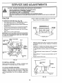
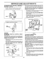
If unit requires more than six (6) feet stopping distance at
high speed in highest gear, then brake must be adjusted.
may have
•
(See Figs. 35 and 36)
Your unit is equipped with an adjustable brake system
which is mounted on the right side of the transaxle.
Park the tractor on level surface. Engage parking brake.
For assistance, there is a belt installation guide decal on the
underside of mower belt cover.
*
BRAKE
•
Remove four (4) hex washer head tapping screws from
shift cover plate located on top of tractor frame_ Remove the cover plate.
•
Loosen jam nut (A) on brake rod (B) at clevis (C) (Fig°
36), If you find it difficult to loosen jam nut (A), remove
cover plate in L.H_ frame rail.
•
Rotate brake rod (b) counterclockwise, turning brake
rod out of clevis (c) four (4) to six (6) turns°
•
Start tractor with transaxle in "N" (neutral) position.
•
Depress clutch/brake pedal to the point where the belt
stops moving. Hold clutch/brake pedal in position by
engaging parking brake., If belt beings to move after
engaging parking brake, depress clutch/brake pedal to
next notch on parking brake.
•
Shut engine off Rotate brake rod (B) clockwise by
hand, turning brake rod into clevis (C) until tighto
Tighten jam nut (A) on brake rod (B) at clevis (C).
•
Reinstall shift cover plate and four (4) mountingscrews°
If cover plate in L.H rail was removed it should be
replaced,
SHIFT COVER PLATE
Install mower to tractor (See "INSTALL MOWER AND
DRIVE BELT" in the Assembly section of this manual.
IDLER ARM NUT
FLAT IDLER
\
MANDREL
CENTRAL
PULLEY
_._
,
FIG. 35
L.H, MANDREL
PULLEY
R,HoMANDREL
PULLEY
FIG. 34
POWER
Fig. 33)
TAKE
OFF
(CLUTCH
PULLEY-
FIG, 36
See
The power take-off clutch should provide years of service.
The clutch incorporates a built in brake that stops the pulley
almost immediately, Eventually, the internal brake will
wear so the mower blades witl not stop as recommended.
Adjustment should be made by your nearest Authorized
Service Center,
21
SERVICE AN
i
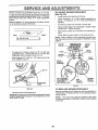
TO REPLACE MOTION
(See Figs. 37 and 38)
DRIVE
n H
TO ADJUST
BELT
FRONT
BELT REMOVAL
Raise hood and disconnect negative ground battery
cable.
•
Set parking brake (to get belt slack)
•
Loosen (do not remove) two (2) engine pulley belt
guide bolts and swivel RH side of belt guide up
Tighten LH, bolt ot hold belt guide in position.
•
Roll belt off engine pulley_
•
Rolf belt off "V" idler, flat idler and clutching
pulleys
.
•
Pull belt off clutch pulley - between pulley and frame.
Pull belt off transaxle pulley.
BELT INSTALLATION
•
Place belt on clutching idler and over clutch pulley, "V"
(narrow) part of belt should engage clutch pulley.
•
Place belt around transaxle pulley,
should engage transaxle pulley
Make sure "V" part of belt engages "V" idler'.
•
Roll belt over engine pulley.
•
Loosen LH, engine putiey belt guide bolt and swivel
belt guide on to RH bolt. Tighten L.H and RH bolts
securely.
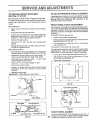
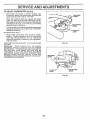
TOE-IN
ADJUSTMENT
TO ADJUST TOE-IN (See Figs, 39 and 40)
tt is important that both tie rods be equal in length before
adjusting toe-in_ Both tie rods should measure approximately 9-5/8" in length (see inset). Adjust if necessary.
.
Loosen jam nuts at adjustment sleeves on tie rod&
°
Adjust both tie rods equally until dimension "A" is 1/8"
to 1/4" less than dimension "B".
•
Tighten jam nuts securely_
"V" part of belt
•
WHEEL
Position front wheels straight ahead.
Measure distance between wheels at front and rear of
tires (dimensions "A" and "B")_
Front dimension "A" should be 1/8" to 1/4" less than
rear dimension "B",.
•
•
Push belt down from engine pulley area Place back
(fiat) side of belt on flat idler (flat idler is next to frame).
ALIGNMENT
Front wheel toe-in is required for proper steering operation,
Toe-in was set at the factory and adjustment should not be
necessary° ff parts in the front axle or sterring mechanism
have been replaced or damaged, check to-in and adjust if
necessary.
TO CHECK TOE-IN (See Fig 39)
idler
•
WHEEL
If steering wheel crossbars are not horizontal (left to right)
when wheels are positioned straight forward, remove
steering wheel and reassemble per instructions in the
Assembly section of this manual
Park the tractor on level surface, Engage parking brake,
For ease of service there is a beit installation guide decal on
bottom side of left footresL it is not necessary to remove
mower'.
•
STEERING
B
j=_
I
•
Release parking brake.
IMPORTANT: CHECK BRAKE ADJUSTMENT.
LH. BOLT'
A
©
,_=,,=
FIG. 39
ADJUSTMENT
SLEEVES
TIE
ROD
O
©
R,H_ BOLT
_UIDE
FIG. 37
JAM NUTS
FLAT IDLER
( ( (_tj_+
1"11
CLUTCH
z_-+_]
".
PULLEY
FIG. 40
\\<_-..._'q.
FRONT
"V"IDLER
CLUTCHINGIDLER TRANSAXLEPULLEY
FIG, 38
22
WHEEL
CAMBER
The front wheel camber is not adjustable on your unit. if
damage has occurred to affect the front wheel camber.
contact your nearest Authorized Service Center,
nln
SERVICE AN
TO REMOVE
WHEEL
i ii
i , n
t,,ll=li,J
ADJUSTMENTS
TO ATTACH JUMPER CABLES •
Connect each end of the RED cable to the POSITIVE
(+) terminal of each battery, taking care not to short
against chassis
•
Connect one end of the BLACK cable to the NEGATIVE (-) terminal of fully charged battery,,
•
Connect the other end of the BLACK cable to good
CHASSIS GROUND, away from fue! tank and battery.
FOR REPAIRS
FRONT WHEEL (See Fig 4l) •
Block up axle securely.
•
Remove hub cap, retaining ring and washers to allow
wheel removal,
.
Repair tire and reassemble_
•
Replace washers and snap retaining ring securely in
axle groove.
•
Replace hub cap,
TO REMOVE CABLES, REVERSE ORDER •
BLACK cable first from chassis and fully charged
battery,
•
RED cable last from both batteries.
WASHERS
RETAINING
RING
TO REPLACE
FUSE
Replace with 30 amp automotive-type plug-in fuse. The
fuse holder is located behind the dash,
TO REPLACE
HEADLIGHT
BULB
•
Raise hood,
•
Pull bulb holder out of the hole in the backside of the
grill.
•
Replace bulb in holder and push bulb holder securely
back into the hole in the backside of the grill.
Close hood,,
CAP
FIGo41
REAR WHEEL •
•
•
Block rear axle securely,
Remove five (5) hub bolts to allow wheel removal.
Repair tire and reassemble Replace and tighten hub
bolts securely,
TO START ENGINE
TERY (See Fig. 42)
WITH A WEAK
•
TO ADJUST ATTACHMENT
(See Fig. 43)
BAT-
CAUTION: Lead-acid batteries generate
explosive gases. Keep sparks, flame and
smoking materials away from batteries,
Always wear eye protection when around
batteries,
LIFT SPRING
•
While holding spring bushing with wrench, loosen jam
nut,
•
Turn adjustment bolt clockwise to extend spring and
reduce lift effort (for heavier attachments).
•
Turn adjustment bolt counterclockwise
tachments),
•
Retighten jam nut against spring bushing.
IMPORTANT; DO NOTADJUST FOR MAXIMUM SPRING
TENSION WHEN USING LIGHT ATTACHMENTS SUCH
AS A MOWER. ADJUST LIFT LEVER SPRING TO AID IN
LIFTING ATTACHMENT. DO NOT OVERPOWER SPRING.
WHEN REMOVING ATTACHMENT, ALWAYS ADJUST TO
SPRING TENSION TO ITS LOWEST POSITION,
If your battery is too weak to start the engine, it should be
recharged.
If "jumper cables" are used for emergency
starting, follow this procedure:
IMPORTANT:
YOUR UNIT IS EQUIPPED
WITH A 12
VOLT NEGATIVE
GROUNDED
SYSTEM°
THE OTHER
VEHICLE
MUST ALSO
BE A t2 VOLT
NEGATIVE
GROUNDED
SYSTEM.
DO NOT USE YOUR TRACTOR
BATTERY TO START OTHER VEHICLES,
ADJUSTMENT
BOLT
SPRING BUSHING
!
JAM NUT
"POSITIVE"
(+)
FIG. 43
FIG. 42
(for lighter at-
23
ATTACHMENT
LIFT SPRING
SERVICE AN
=
=
ADJ
STMENTS
H H IHHHH
TO REMOVE HOOD AND GRILL ASSEMBLY
(See Figs. 44 and 45)
°
Lift hood, Disconnect headlight wiring connection.
°
Unscrew one screw at rear of each side panel.
TO ADJUST
CONTROL
(See Fig. 47)
°
With engine not running, move choke control (located
on dash panel) to full "CHOKE" position.
-
Remove air cleaner cover, filter and cartridge plat to
expose carburetor choke (see "AIR FILTER" in Maintenance section).
,
Choke should be closed. If it is not, loosen casing clamp
screw and move choke cable until choke is completely
closed. Tighten casing clamp screw securely_
Reassemble air cleaner_
•
FIG, 44
•
CHOKE
The choke control has been preset at the factory and
adjustment should not be necessary. Check adjustment as
described below before loosening cablev If adjustment is
necessary, proceed as follows:
CHOKE CLOSED
Pivot hood and side panel forward and lift off tractor.
To replace, reverse above procedure.
==CHOKE
LEVER
WIRE
CONNECTION
CASING J
CLAMP
SCREW
FIG. 45
ENGINE
TO ADJUST
FIG. 47
THROTTLE
CONTROL
CABLE
TO ADJUST
(See Fig. 46)
The throttle control has been preset at the factory and
adjustment should not be necessary. Check adjustment as
described below before loosening cable. If adjustment is
necessary, proceed as follows:
•
With engine not running, move throttle control lever to
"FAST" position.
•
Check that swivel is against side of quarter circle, If it
is not, loosen cable clamp screw and pull cable back
until swivel is against quarter circle. Tighten cable
clamp screw securely.
CARBURETOR
(See Figs. 48 and 49)
The carburetor has been present at the factory and adjustment should not be necessary. However, minor adiustment may be required to compensate for differences in
uel, temperature, altitude or load. If the carburetor does
not need adjustment, proceed as follows:
in general, turning the mixture screw In (clockwise) decreases the supply of fuel to the engine giving a leaner fuel/
air mixture. Turning the mixture screw out (counterclockwise) increases the supply of fuel to the engine giving a
richer fuel/air mixture..
IMPORTANT:
DAMAGE TO THE NEEDLES AND THE
SEATS IN CARBURETOR MAY RESULT IF SCREW IS
TURNED IN TOO TIGHT.
PRELIM INARY S ETTI NG -
CLAMPSCREW
QUARTER
CIRCLE
•
Be sure you have a clean air filter', and the throttle
control cable and choke are adjusted properly (see
above).
,
With engine off turn idle mixture screw in (clockwise)
closing it finger tight and then turn out (counterclockwise) 1-1/4 to 1-1/2 turns.
FINAL SETTING •
SWIVEL
FIG. 46
24
Start engine and allow to warm for five minutes. Make
final adjustmen!s with engine running and shift/motion
control lever in NEUTRAL' position°
SERVICE AN
H=_
ill illll illl IIHi I=H==
TO ADJUST
•
•
•
= IHIH= H=I=HH=Hlll
(cont'd)
With throttle control lever in "SLOW" position, hoId
throttle lever against idle speed screw and adjust idef
spped screw to obtain 1200 to t400 RPM
IDIP SPEED
_CREW
While still holding throttle lever against idel speed
screw, turn idle mixture screw in (clockwise) until engine begins to die and then turn out (counterclockwise)
until engine runs rough Turn screw to a point midway
between those two positions_
IDLE MIXTURE
SCREW
Continue to hold throttle lever against idle speed screw
and adjust idle speed screw to obtain 900 to 1200 RP M.
Release throttle lever
ACCELERATION
•
CARBURETOR
ADJUSTMENTS
TEST
LEVER
-
Move throttle control tever from "SLOW to "FAST"
position.
If engine hesitates or dies, turn idle mixture
screw out (counterclockwise)
1/8 turn. Repeat test
and continue to adjust, if necessary, until engine accelerates smoothly.
FIG. 48
High speed stop is factory adjusted. Do not adjust-damage
may result.
IMPORTANT:
NEVER TAMPER
WITH THE ENGINE
GOVERNOR,
WHICH IS FACTORY
SET FOR PROPER
ENGINE SPEED. OVERSPEED1NG
THE ENGINE ABOVE
THE FACTORY
HiGH
SPEED
SETTING
CAN
BE
DANGEROUS.
IF YOU THINKTHE
ENGINE-GOVERNED
HiGH SPEED NEEDS ADJUSTING,
CONTACT
YOUR
NEAREST
SEARS
SERVICE
CENTER,
WHICH
HAS
PROPER EQUIPMENT
AND EXPERI ENCE TO MAKE ANY
NECESSARY
ADJUSTMENTS
IDLE MIXTURE
SCREW
THRO3-rLE
LEVER
FIG. 49
25
STORAGE
ENGINE
Immediately prepare your' unit for storage at the end of the
season or if the unit will not be used for 30 days or more
CAUTION:
FUEL SYSTEM
IMPORTANT:
IT IS IMPORTANT TO PREVENT GUM
DEPOSITS FROM FORMING IN ESSENTIAL FUEL
SYSTEM PARTS SUCH AS CARBURETOR, FUEL FILTER,
FUEL HOSE, OR TANK DURING STORAGE, ALSO,
EXPERIENCE INDICATES THAT ALCOHOL BLENDED
FUELS (CALLED GASOHOL OR USING ETHANOL OR
METHANOL) CAN ATTRACT MOISTURE WHICH LEADS
TO SEPARATION AND FORMATION OF ACIDS DURING
STORAGE
ACIDIC GAS CAN DAMAGE THE FUEL
SYSTEM OF AN ENGINE WHILE IN STORAGE.
Never store the tractor wtth
where
fumes
may
reach
an open
flame
gasoline
in the
tank
inside
a building
or spark, Allow the engine to cool
before storing tn any enclosure.
TRACTOR
•
Drain the fuel tank°
Remove mower from unit for winter storage_ When mower
is to be stored for a period of time, clean it thoroughly,
remove alf dirt, grease, leaves, etc. Give blades and
underside of housing a good coat of grease or rust preventative. Store in a clean, dry area°
•
Start the engine and let it run until the fuel lines and
carburetor are empty.
•
•
Clean entire tractor (See "CLEANING" in the Maintenance section of this manual).
•
Never' use engine or carburetor' cleaner products in the
fuel tank or permanent damage may occur.
Use fresh fuel next season,
•
Inspect and replace belts, if necessary (See belt replacement instructions in the Service and Adjustments
section of this manual),
,
Lubricate as shown in the Maintenance section of this
manual.
•
Be sure that all nuts, bolts and screws are securely
fastened. Inspect moving parts for' damage, breakage
and wear. Replace if necessary.
•
NOTE:
Fuel stabilizer' is an acceptable alternative in
minimizing the formation of fuel gum deposits during storage. Add stabilizer to gasoline in fuel tank or storage
container. Run engine at least 10 minutes after adding
stabilizer to allow the stabilizer to reach the carburetor, Do
not drain the gas tank and carburetor if using fuel stabilizero
ENGINE
OIL
Drain oil (with engine warm) and replace with clean engine
oil. (See "ENGINE" in the Maintenance section of this
manua0.
Touch up all rusted or chipped paint surfaces; sand
lightly before painting,
BATTERY
CYLINDERS
.
Fully charge the battery for storage,
•
Remove spark plug(s).
•
After a period of time in storage, batter,/may
recharging,
require
•
Pour one ounce of oil through spark plug hole(s) into
cylinder(s).
,
To help prevent corrosion and power leakage during
long periods of storage, battery cables should be
disconnected and battery cleaned thoroughly (see "TO
CLEAN BATTERY AND TERMINALS" in the Mainte.
nance section of this manual)_
-
Turn ignition key to"START" position for afewseconds
to distribute oil
•
Replace with new spark plug(s),
•
•
OTHER
After cleaning, leave cables disconnected and place
cables where they cannot come in contact with battery
terminals.
Be sure battery drain tube is securely attached to drain
in battery tray_
•
Do not store gasoline from one season to another.
•
Replace your gasoline can if your' can starts to rust.
Rust and/or dirt in your gasoline will cause problems.
•
If possible, store your unit indoors and cover it to give
protection from dust and dirt.
•
Cover your unit with a suitable protective cover that
does not retain moisture Do net use plastic, Plastic
cannot breathe which allows condensation to form and
wil! cause your unit to rust.
IMPORTANT: NEVER COVER TRACTOR WHILE ENGINE
AND EXHAUST AREAS ARE STILL WARM.
26
TROUBLESHOOTING
PROBLEM
CAUSE
Will not start
1,
Out of fuel,
2
3
4.
5
6.
7
Engine not "CHOKED"
Engine flooded
Bad spark plug
Dirty air filter,
Dirty fuet filter,
Water in fuel,
8,
9,
10
Hard to start
1.
2
3
4,
5,
6,
7
8
POmNTS
CORRECTION
1,
Fill fuel tank,
propedy.
2,
3.
4.
5
6.
7
Loose or damaged wiring
Carburetor out of adjustment.
Engine valves out of adjustment.
8
9.
10.
See TO START ENGINE in Operation section
Wait several minutes before attempting to start,
Replace spark plug
Clean/replace air filter
Replace fuel filter
Drain fuel tank and carburetor, refill tank with fresh
gasoline and rap}ace fuel filter
Check all wiring,
Contact Sears Service Department.
Contact Sears Service Department
Dirty air filter
Bad sparkplug,
Weak or dead battery,
D_rty fuet filter,
Stale or dirty fuel
Loose or damaged wiring
Carburetor out of adjustment
Engine valves out of adjustment,
1
2
3,
4,
5
6.
7
8.
Ciutchlbrake pedal not depressed
Attachment clutchls engaged.
Spark plug wire is disconnected.
Weak or dead battery
Blown fuse.
1.
2.
3.
4,
5.
6
7.
8
9
10
Clean/replace air fitter
Reptace sparkplug
Recharge or replace battery
Replace fuel filter
Drain fuel tank and refill with fresh gasoline
Check all wiring
Contact Sears Service Department
Contact Sears Service Department.
ii
Engine will not turn over
t
2,
3,
4
5,
6
7
8,
9,
10,
Engine cltcks but will not
start
Lossofpower
1,
2,
Weak or dead battery.
Corroded battery terminals.
3.
4,
Loose or damaged wiring
Faulty solenoid or starter.
1
2
3
4
5
6
7,
8
9.
Cutting too much grass/too fast.
Throttle in "CHOKE" position,
Build-up of grass, leaves and trash under mower
Dirty air _tar.
Low oil leveVdtrty oil
Faulty spark plug
Dirty fuel filter,
Stale or dirty fuel,
Water in fuel.
10
1t.
12
13
14
15
Excessive vibration
Corroded battery terminals,,
Loose or damaged wiring
Faulty Ignition switch
FauIty solenoid or starter,
Fautty operator presence switch(as),
Spark plug wire loose
Dirty engine air screenlfins
Dirty/clogged muffler.
Loose or damaged wiring.
Carburetor out of adjustment.
Engine valves out of adjustment,
Depress clutch/brake pedal
D_sengage attachment clutch
Connect wire to spark plug.
Recharge or repiace battery
RepEace fuse,
Clean battery terminals
Check all wiring
Check/replace ignttion switch
Check/replace solenoid or starter
Contact Sears Service Department
1
2,
3,
4,
Recharge or replace battery
Clean battery terminals,
Check all wiring
Check/replace solenoid or starter
1
2,
3
4
5
Set in "Higher Cut" position/reduce speed
Adjust throttle conlrol
Clean underside of mower housing
Clean/replace air filler
Check oil leveVchange oil
6.
7
8
9
Clean and regap or change spark plug
Replace fuei filter,
Drain fuel tank and refill with fresh gasoline,
Drain fuet tank and carburetor, refill tank with fresh
gasoline and replace fuel filter
10,
11_
12
13.
14
15
Connect and tighten spark plug wire
Ciean engine air screen!fins
Clean/replace muffler
Check altwidng,
Contast Sears Service Department.
Contact Sears Service Department
1
2
Worn, bent or loose blade,
Bent blade mandrel
1
2
Replace b_ade Tighten blade bolt
Replace blade mandrel.
3
Loose/damaged
3
Tightenloose
part(s).
27
part(s)
Replace damaged parts
j,j
1,1,
TROUBLESHOOTmNG
J
J ILLULU
,,,,,,I
,II,,H,I ,,I,,,,,
,,
POmNT$
, I,,,,,,,
,,N,
I1,1
PROBLEM
CAUSE
CORRECTION
Engtne continues to run
when operator leaves seat
with attachment clutch
engaged
I
Faulty operator-safety presence contrei system
1_
Check wiring, switches and connections If not
corrected, contact Sears Service Department
Poor cut - uneven
1
2,
Worn, bent or loose blade.
Mower deck not level
3
4
Buildup of grass, leaves, and trash under mower
Bent blade mandrel
1
2.
3
Replace blade Tighten blade bolt.
Level mower deck_
Clean underside of mower housing
4
Replace blade mandrel
1.
2
3
4.
5
Obstruction in clutch mechanism,
Mower drive belt out of adjustment
Worn/damaged mower drive belt.
Frozen idler pulley.
Frozen blade mandrel
1.
Remove obstruction
2.
3
4,
5
Adjust mower drive belt.
Replace mower drive belt
Replace idler pulley.
Replace blade mandrel
Engine speed toosIow
Travel speed too fast
Wet grass_
Mower deck not level
Low/uneven tire air pressure
Worn, bent or loose blade,
Buildup of grass, leaves and trash under mower
Mower drive belt worn or out of adjustment
Blades improperly installed.
Improper bEades used
1
2
3
4,.
5
6
7.
8
9
10,
Place throttJe control in "FAST" position.
Shift to slower speed.
Atlow grass to dry before mowing,
Level mower deck,
Checktires for proper air pressure.
Replace/sharpen blade. Tighten blade bert
Clean underside of mower housing
Replace/adjust mower drive beit
Reinstall b{ades sharp edge down,
Replace with b_ades listed in this manual
Mower blades will not
rotate
Poor grass discharge
Headlight(s) not working
(If so equipped)
1,
2,
3
4
5
6.
7
8.
9
10.
1,
2
3.
4
5
Switch is "OFF".,
Bulb(s) burned out
Faulty light switch,
Loose or damaged wiring,
Btown fuse
1.
Turn switch "ON".
2
3
4
5
Replace bulb(s),
Check/repIace light switch
Check wiring and connections
Replace fuse.
i,,
Battery will not charge
, i, ,,,i
1
2
Bad battery ceil(s).
Poor cable connect_OnSr
1.
2.
Replace battery,_
Check/clean all connections,
3
Faulty regulator (if so equipped),
3
Replace regulator
28
,H,HH,,,,I,,,,,,,
18 HP 44" RIDING GARDEN
TRACTOR
- MODEL NUMBER
917.255930
SCHEMATIC
RED O1110
"Ill
0 ,oK
BATTERY
FUSE 30 AMP,
t
I
RED
)
RED
I
AMME_
WHITE
_-0_
STARTER
I
IC
Dt
©,
s M_
F
t
_
I
B
IGNITION
SWITCH
BLACK
_
/-7-7
E_
I
ELECTRIC CLUTCH
AU--_ --_
PTO
(DISENGAGED)
BLACK
LIFT KIT --4
WIRING
IGNITION
UNIT
BLACK
RED
5 AMPS DC (POS,)
RELAY
22 VOLTS AG (MtN,',
5 AMPS
@
DO
ALTERNATOR
(BATTERY tN LINE)
NON-REMOVABLE
B
rr--n
S
rr--n
IGNITIONSWITCH
POSITION
....
,,,,
OFF
ON
START
CIRCUIT
REMOVABLE
CONNECTIONS
CONNECTIONS
c I] t] B
D
F It
0 IIJE
UA
WIRING INSULATED
PTO SWITCH
,
,
M+G
B+L
B+S
[I POSITION
OFF
ON
CIRCUIT
B+E,C+D
B+A,C+F
29
J
CLIPS
NOTE: IF WIRING INSULATED CLIPS WERE
REMOVED FOR SERVICING OF UNIT, THEY
SHOULD BE REPLACED TO PROPERLY
SECURE YOLJR WIRING.
REPAUR PARTS
18 HP 44" RIDING
LAWN TRACTOR
- - MODEL NUMBER
917.255930
ELECTRICAL
23
18
)
46
30
REPAgR PARTS
18 HP 44" RIDING LAWN
TRACTOR
-- MODEL
NUMBER
917.255930
ELECTRICAL
KEY
NO.
PART
NO.
1
2
3
4
5
6
7
8
9
10
11
12
13
14
109310X
STD365402
!09787X
109788X
4171R
110712X
121537X
7603J
100541K
109596X
109081X
10090400
STD541225
17190408
15
16
104445X
71031008
17
18
19
20
21
22
23
24
25
26
73951000
1063t5X
121478X
4152J
108824X
74610628
STD523707
121080X
11050600
4021J
DESCRIPTION
KEY
NO,
Key
Switch, Ignition
Bezel, Ignition
Nut, Ignition
Clip
Switch, Light
Battery
Tray, Battery
Tube, Drain
Clamp, Hose
Solenoid
Washer, Lock 1/4
*Nut, Hex, Jam 1/4-20
Screw, Hex Washer Head, Thread
Cutting 1/4-20 x 1/2
Switch, Interlock
Screw, HexWashsrHead
#10-32 x 1/2
Nut, Keps #10-32
Diode Assembly
Harness, Ignition
Bulb, Headlight
Fuse
Bolt, Hex 3/8-24 x 1-3/4
* Bolt, Hex 3/8-16 x 3/4
Cable, Ground
Washer, Lock, External Tooth 3/8
Switch, P.ToO.
PART
NOo
27
28
29
30
31
32
33
34
35
36
37
39
40
41
42
43
44
45
46
48
49
50
--
4022J
4799J
719J
74641008
5115J
I09550X
!06367X
108170X
19132203
STD551137
72240460
123198X
102476X
STD522507
STD551025
STD541025
STD551125
110859X
121305X
I09748X
121264X
121433X
I01539X
--
127668
(_)13
B
C
14
Nut, Hex
Cable, Battery
Cover, Terminal
Screw #!0-32 x 1/2
Cable, Starter
Clutch, Electric
Spacer, Clutch
Stop, Ctutch
Washer
*Washer, Lock 3/8
Bolt, Carriage t/4-20x 7-1/2
*Nut, Wing 1/4-20
Guard, Terminal
*Bolt, Hex 1/4-20x3/4
*Washer 9/32 x 5/8 x 16 Gauge
* Nut, Hex 1/4-20
*Washer, Lock 1/4
Harness, Light Socket
Switch, Plunger
Relay, Operator Presence
Cap Set, Battery
Ammeter
Sheet, lnstruction,'Tractor, 15 °
Slope
Manual, Owner's
*STANDARD HARDWARE-NOTE:
A
DESCRIPTION
D
16
31
_._J 25
PURCHASE LOCALLY
All component dimensions given in UoSo inches.
1 inch = 2&4 mm
F
30
REPAUR PARTS
18 HP 44" RIDING LAWN TRACTOR
- - MODEL NUMBER
917.255930
CHASSIS AND ENCLOSURES
52
44
46
26
_\26
Hr.,
37
79
32
REPAUR PARTS
18 HP 44" RIDING
LAWN TRACTOR
- - MODEL
NUMBER
917.255930
CHASSIS AND ENCLOSURES
KEY PART
NO. NO.
KEY PART
NO. NO.
DESCRIPTION
1
2
3
4
5
6
8
9
10
11
13
t5
127438X
124294X
105529X
120579X
73680500
275tR
126656X
73680600
121642X417
106202X
STD523707
17490608
16
174906t6
17
t9
21
22
23
24
25
26
27
28
29
30
3t
32
33
34
35
36
37
39
40
41
42
43
44
45
46
47
48
49
51
52
53
I 05511X
!24181X
105531X
105509X
106020X
123549X
106082X
123487X
7834R
7833R
105465X417
!05466X
105464X417
110892X
110893X
7982J
74760716
73680700
108403X417
108410X417
130523
121055X
106013X417
1'I0875X
105528X
108512X
108513X
106003X
106004X
110897X
108067X
106091X
106090X
A
_5
Seat
Pan Seat
Bolt, Shoulder
Nut, Pal
Nut, Crownlock 5/16-18
Clip
Bracket, Pivot, Seat
Nut, Crownlock 3/8-16
Fender
Reflector, Taillight
*Bolt, Hex 3/8-16x3/4
Screw, Hex Washer Head, Thd.
Roll, 3/8-16 x 1/2
Screw, Hex Washer Head, Thdo
Roll. 3/8-16 x 1
Strap, Fender
Spring, Compression
Nut, Push
Bracket, Fender
Tank, Fuel
Cap, Fuel
Pad, Spacer
Clamp, Hose
Line, Fuel
Line, Fuel
Footrest, LH.
Pad, Footrest
Footrest, R.H.
Rail, Frame, R.H_
Rail, Frame, L.Ho
Drawbar
Bolt, Hex 7/16-14 x !
Nut, Crownlock 7/16TI4
Panel, Side, R,Ho
Panel, Side, LIH.
Bracket, Pivot, Frame, R.H
Bracket, Pivot, Frame, LH.
Hood
Shield, Heat, Front
Grill
Bracket, Pivot, Grill, R.H.
Bracket, Pivot, Grill, LH.
Lens, R.H.
Lens, LH.
Bezel
Nut, Pat
Hinge, R.H.
Hinge, L,H
B
C
_81
D
E
F
DESCRIPTION
54
58
59
62
63
64
70
71
72
73
74
75
77
79
80
81
82
84
85
110350X4!7
3545J
8710J
19131416
106092X
106088X
106909X
106910X
I08402X
124238X
19131614
106086X
105036X
105500X
127018X
19131312
120068X
19171912
17490612
86
87
88
89
90
91
92
-----
121251X
121246X
!21248X
72170410
121249X
121250X
123976X
105568X
128259
105806X
126771X
106814X
106813X
105567X
130595
130596
105801X
106974X
127521
106868X
4900J
-------
*STANADARD
NOTE:
G
H
(_7t
_9
33
J
Strap, Grill
Bushing
Stem, Fuel Tank
Washer 13/32 x 7/8 x 16 Gauge
Support, Heat Shield
Strip, Foam
Screw, Special
Washer
U-Clip
Cap, Spring
Washer t3/32 x 1 x 14 Gauge
Strip, Foam
Strip, Foam
Retainer, Belt, Lower
Bolt, Shoulder 5/16q8 x .62
Washer 13/32 x 13/16 x 12 Gauge
Knob
Washer 17/32 x 13/16 x 12 Gauge
Screw, Hex, Thread Rolling
3/8-16 x 3/4
Strip, Foam
Switch, Bracket
Snap Bushing
Bolt, Carriage 1/4 x 1-1/4
Spacer, Split
Spring
Nut, Hex, Flange 1/4-20
Decal, Grill, Stripe
Decal, Grill
Decal, Grill
Decai, HP, Hood
Decal, Stripe, Side Panel, R.H.
Decal, Stripe, Side Panel, L.H.
Decal, Chassis, Speed/Deck Size
Decal, Stripe, Hood, R_Ho
Decal, Stripe, Hood, Loll.
Decal, Fender, Logo
Decal, Caution
Decai, USA
Decal, Drive Belt Schematic
Decal Clutch/Brake, Footrest
HARDWARE--PURCHASE
LOCALLY
All component dimensions given in U, S. inches.
1 inch = 25.4 mm.
L
M
_62
P
U
Q
®84
R
_92
S
T
REPAIR PARTS
18 HP 44" RIDING
LAWN TRACTOR
- - MODEL NUMBER
917.255930
DRIVE
86
x
130
32
64
,/
98
127
92
OPTIONAL
Spark Arrester
EQUIPMENT
Kit
K
L
M
N
O
P
O
R
@62_
34
S
T
U
V
W
]
Y
REPAUR PARTS
18 HP 44" RIDING
LAWN TRACTOR
- - MODEL NUMBER
917.255930
DRIVE
KEY PART
NO. NO,
1
2
19132616
110864X
3
4
13200300
.......
5
6
8
9
10
11
12
13
14
15
16
17
18
19
20
23
25
26
27
29
30
31
32
36
37
38
39
40
42
43
44
45
46
47
48
49
50
51
13280324
110890X
!10887X
8545J
74570412
STD551125
1!0867X
STD523707
74780524
STD55!131
STD541031
73680600
121355X
STD551137
19131614
12t063X
10t344L
122825X
122824X
72110614
STD533707
102403X
19131316
121356X
207J
12000039
121361X
STD523715
121357X
STD560907
101356L
104360X
121358X
19131413
121360X
104577X
STD523710
17190516
54
55
56
57
58
59
60
61
62
63
64
65
66
67
69
70
122253X
105598X
100196K
73680500
122268X
110883X
120404X
74760716
STD551143
120332X
9204H
104375X
121749X
STD571812
124559X
17720410
KEY PART
NO. NO,
DESCRIPTION
Washer t3/32 x 1-5/8x 16 Gauge
Engine, Briggs and Stratton, Model
Number 422437, Type Number
1266-0t
Elbow, STD 90 °
Plug, Oil Drain (Order from Engine
Manufacturer)
Nipple, Pipe 3/8
Tube, Exhaust
Muffler
Gasket, Muffler
Screw, Socket Head 1/4-20x 3/4
*Washer, Lock 1/4
Base, Engine
* Bolt, Hex 3/8-16 x 3/4
Bolt 5/16-18 x 1-1/2
Washer, Lock 5/16
Nut 5/16-18
Nut, Crownlock 3/8_16
Pulley, Ground Drive
*Washer, Lock 3/8
Washer 13/32 x 1 x 14 Gauge
Bracket, V-Pulley, Mule Drive
Pulley
Bracket, Idler, Flat
Guard, Belt, Mule Drive
Bolt, Carriage 3/8-16 x 1-3/4
*Bolt, Carriage 3/8-16 x 3/4
idler, Flat
*Washer 13/32 x !3/16x 16 Gauge
Bracket, Clutch (inc. Key No. t06)
Washer, Hardened
Ktip, Ring
Idler, Grooved
*Bolt, Hex 3/8_16x 1-3/4
Spring, Extension, Clutch
* Pin, Cotter 3/32 x3/4
Rod, C_utch
idler, F_at
Retainer, Spring
Washer 13/32 x 7/8 x 13 Gauge
Retainer, Belt
Adapter
*Bott, Hex 3/8-16x1Grade5
Screw, Hex, Tread Cutting
5/16-18 x 1
Rod, Shift, Hi-Lo
Bracket, Rod, Shift
Knob
Locknut 5/16-18
Spring Cllp, Connecting Link
V-Belt
Bracket, Support, Transaxle
Bolt, Hex 7/16-14 x 1
*Washer, Lock 7/t6
Pulley, Transaxle
Locknut t/2-20
Shaft, Foot Pedal
Washer 25/32 x 1-1/4 x 16 Gauge
*Pin, Roll 3/16x1-1/4
Control, Throttle
Screw, Hex, Thread Cutting
1/4-20 x 1
71
72
73
74
75
76
DESCRIPTION
121389X
11050600
STD541!37
8883R
677A637
74370612
Control, Choke
Washer, Lock, Externat Tooth 3/8
* Nut, Hex 3/8-24
Cover, Pedat
Bracket, Brake
Screw, Machine, Flat Head
3/8-16 x 3/4
77 74760614
Bolt, Hex 3/8 _16 x 7/8
78 101122M
Band, Brake
79 72140405
Bolt, Carriage t/4-20 x 5/8
80 STD54t025
*Nut, Hex 1/4-20
81 7229J
Guide, Rod, Brake
82 1685H
Locknut 5/16-18
83 STD533110
*Bolt, Carriage 5/16-18x3/4
84 5308J
Rod, Brake
85 7241J
Spring, Compression
86 73530600
Locknut 3/8-24
87 100604K
Yoke
88 5102J
Pin, Clevis
89 124236X
Cap, Plunger
90 109767X
Rod, Parking Brake
92 634A692
Bushing and Wheel Hub
93 7563R
Washer, Thrust, Axle
94 12000034
Klip, Ring
95 1304H
Bolt, Hub
96 106277X361
Wheel, Rear
97 105588X
Tire, Rear
98 7154J
Tube, Rear
99 65139
Valve, Tire
t00 59192
Cap, Valve
101 214J
Drum, Brake
102 STD5414t0
*Locknut #10-24
103 633A109
Gear Shift Lever Assembly
104 2228M
Key, Woodruff
105 74760720
Bolt, Hex 7/16-14 x 1-1/4
106 105706X
Bearing, idler
108 9858M1
Key, Woodruff
t09 5304J
Actuator, Switch, interlock
110 74321016
Screw, Finr #10-24 x !
11t 2751R
Clip
t12 104601X
Bracket, interlock
113 STD522507
*Bolt, Hex 1/4-20x3/4
114 73680400
Nut, Crowntock 1/4-20
115 19131210
Washer 13/32 x 3/4 x10 Gauge
1t6 73680700
Nut, Crownlock 7/16-14
117 11050500
Washer, Lock, External Tooth 5/16
118 76020816
Pin, Cotter 1/4 x 1
119 101358K
Bracket, Assembly Clutch
120 19131612
Washer 13/32 x 1 x 12 Gauge
122 72140506
Bolt, Carriage 5/16-18x3/4
126 110895X
Nyliner
127 120615X
Spark Arrester Kit
-124607X
Decal, Engine
*STANDARD
NOTE:
35
HARDWARE--PURCHASE
LOCALLY
ALl component dimensions given in U. So inches.
1 inch = 254 mm
REPAIR PARTS
18 HP 44" RiDiNG LAWN TRACTOR
- - MODEL NUMBER
917.255930
STEERING ASSEMBLY
57
56
A
10
83-_
10
17
21
74
2/
36
REPAUR PARTS
18 HP 44" RIDING
LAWN TRACTOR
- - MODEL
NUMBER
917.255930
STEERING ASSEMBLY
KEY PART
NO. NO,
1
2
3
106230X
8134H
106228X361
4
5
6
7
8
9
10
11
12
13
14
15
16
17
18
19
20
21
22
23
24
25
26
27
28
29
30
31
32
33
34
278H
9040H
t06045X
6266H
12000029
5284J
STD523707
73680600
674A243
1309H
5298J
74781044
STD551162
STD541062
6855M
106046X
120424X
1 I0497X
STD551137
STD541137
5292J
108137X
19292016
109849X
STD523720
102933X
102439X
104239X
72110608
101274N
17490612
35
36
37
38
39
40
4I
42
43
44
45
46
47
48
49
102458X
12000034
100713N
100711L
19133808
106014X
9038R
105519X
120028X
105525X
19171416
72110622
121235X
106042X
17720408
KEY PART
NO. NO,
DESCRIPTION
Tire
Tube, Front
Front Wheel (Includes Key
Numbers 3 and 4)
Fitting, Grease
Bearing
Spindle, R,H
Bearing, Axle
Klip, Ring
Bracket, Axle
*Bolt, Hex 3/8-16x3/4
Nut, Crownlock 3/8-16
Axle, Front (Includes Key No. 13)
Beadng
Tube, Pivot, Axle
Bolt, Hex 5/8-11 x 2-3/4 Grade 5
*Washer, Lock 5/8
*Nut, Hex 5/8-11
Fitting, Grease
Spindle, L.H
Sector Assembly
Link, Drag
*Washer, Lock 3/8
*Nut, Hex 3/8-24
Bushing, Bellcrank
Bellcrank
Washer 29/32 x 1-1/4 x 16 Gauge
Rod, Tie
*Bolt, Hex 3/8-16x2Grade5
Spacer, Split
Bracket, Support, Steering
Bearing, Flanged
Bolt, Carriage 3/8-16 x 1 Grade 5
Support, Steering
Screw, Hex Washer Head, Thread
Rolling 3/8-16 x 3/4
Shaft, Steering
Klip, Ring
Wheel, Steering
Adapter, Steering
Washer
Sleeve, Steering
Bearing
Dash, Lower
Dash
Bracket, Support, Dash
Washer 17!32x7/Sx
16Gauge
Bolt, Carriage 3/8-16 x 2-3/4
Spacer
Cover, Gate, Shift
Screw, Hex Washer Head, Thread
Cutting t/4-20 x 1/2
A
B
lo
C
92
D
34
E
F
49
100710L
74780880
73680800
19172610
120542X
677A451
7190J
STD523720
19131413
STD541037
5213J
73680500
7985J
65139
59192
I24557X
106615X
2751 R
109850X
109851X
7919J
73700600
STD541337
STD533107
121749X
121748X
74930516
104757X
100644K
19111416
STD523710
100207K
120199X
121177X
110946X
19132007
8022J
121748X
121232X
74180412
19091216
73510400
4171R
105810X
108456X
51
52
53
54
55
56
57
58
59
60
61
62
63
64
65
66
68
69
70
71
72
73
74
75
76
77
78
79
80
81
82
83
85
86
87
88
89
90
91
92
93
94
95
*STANDARD
@93
G
H
sB
f_
g4
U
29
insert, Steering Wheel
*Bolt, Hex 1/2-13x5
Nut, Crowntock 1/2-13
Washer 17/32 x 1-5/8 x 10
Bracket, Idler
Pulley, Idler
Spring
* Bolt, Hex 3/8-I6 x 2-1/4
Washer 13/32 x 7/8 x !3 Gauge
* Nut, Hex 3/8-16
Bracket, Frame Front
Nut, Crownlock 5/16-18
Support, Battery
Stem, Valve
Cap, Valve
Dashplate
Pin, Mounting, Idler Bracket
Clip
Joint, Tie Rod, R.H. Thread
Joint, Tie Rod, L H. Thread
Rod, Tie
Nut, Hex, Jam 3/8-24 L.H_
* Nut, Hex, Jam 3/8-24 R.H.
* Bolt, Carriage 5/I6-18 x 3/4
Washer
13/32 x I-1/4 x 16 Gauge
Washer 25/32 x 1-1/4 x 16 Gauge
Bolt, Hex 5/16-18 x 1
Cap, Hub, Front
Bushing, Handle
Washer tl/32 x 7/8 x 16 Gauge
*Bolt, Hex 3/8-16 x 1 Garde 5
Clip 3/8
Tube
Collar
Stop, Spindle
Washer t3/32 x 1-1/4 x 7 Gauge
Plug, Dash
Washer 25/32 x 1-5/8 x 16 Gauge
Cap, Spindle
Screw, Machine 1/4-20 x 3/4
Washer 9/32 x 3/4 x 16 Gauge
Nut, Hex, Keps 1/4-20
Clip
Decal, Steering Wheel Insert
Decal, Instruction, Operating, Dash
HARDWARE--PURCHASE
LOCALLY
NOTE: All component dimensions given in U.S. inches.
1 inch = 25.4 mm
,_
J
22
58
_11
DESCRIPTION
_
11
¢_ 22
60
L
75
M
46
@ 62
,:_ 22
6O
(_sg
K
45
I=l4,
_6o
37
¢_60
N
32
78
45
80
22
_
81
8o @52
REPAIR PARTS
18 HP 44" RIDING
LAWN TRACTOR
- = MODEL
NUMBER
917.255930
LIFT ADJUSTMENT
61
56
J
66
18
17
64
J
6
t_
co
2
23
16
?
I
40
/
41
35_
42
49
16
5_
KK
REPAIR PARTS
18 HP 44" RiDiNG
LAWN TRACTOR
== MODEL
NUMBER
917.255930
LIFT ADJUSTMENT
KEY PART
NO. NO.
1
2
3
4
5
6
7
8
9
10
11
12
13
14
15
16
17
18
19
20
21
22
23
24
25
26
27
28
29
30
31
32
33
34
35
36
100734K
110807X
110811X
STD570907
2876H
19131016
121794X
121387X
STD523107
73680500
120350X
STD522505
73680400
106351X
110436X
73350600
19112410
123934X
10040500
121366X
19091216
73631000
124217X
110810X
19151216
12000037
7594J
7901J
73900400
7596J
105503)(
4939M
122365X
121002X
121006X
122364X
KEY PART
NO. NO.
DESCRIPTION
Handle, Adjust, Lift
Nut
Rod, Adjust, Lift
* Pin, Cotter 3/32 x 3/4
Spring
Washer 13/32 x 5/8 x 16 Gauge
Cover, Access
Shield, Heat, Rear
* Bolt, Hex 5/16-18 x 3/4
Nut, Crownlock 5/16-18
Brace, Heat Shield
* Bolt, Hex 1/4-20 x 1/2 Grade 5
Nut. Crowntock 1/4-20
Plug
Grommet, Split
Nut, Hex, Jam 3/8-16 UNC
Washer 11/32 x 1-1/2 x 10 Gauge
Scale, Height Indicator
Washer, Lock Heavy Helical Spring
Pump, Fuel
Washer 9/32 x 3/4 x t6 Gauge
Locknut #10-24
Shaft, Lift
Trunnion. Depth Stop
Washer 15/32 x 3/4 x t6 Gauge
Klip, Ring
Bracket, Lift, L.H.
Bolt, Shoulder
Nut, He)<,Flange 1/4-20
Link, Lift, LH.
Link, Lift, R.H.
Retainer, Spring
Button. Plunger
Lever, Lift
Rod, Detent
Plunger, Lever
B
_13
C
_
STD523710
* Bolt, Hex 3/8-16 x 1
12563!X
Grip, Handle
Bolt. Hex 3/8-16 x 1-1/2
74760624
19171616
Washer 17/32 x 1-1/!6 x 13 Gauge
9135R
Spring, Retainer
105429X
Arm, Suspension
105413X
Stud, Pivot Center
STD551150
*Washer, Lock 1/2
STD541050
*Nut, Hex 1/2-13
105501X
Bracket, Suspension, Mower
STD533707
* Bolt, Carriage 3/8-t 6 x 3/4
Nut, Crownlock 3/8-16
73680600
674A247
Spring Assembly, Assist, Uft
126651X
Guard, Belt, Engine
STD533110
*Bolt, Carriage 5/16-18 x 1
19111610
Washer 11/32 x ! x 10 Gauge
121045X
Panel, Pnt. Side, R.H.
121046X
Panel, Pnt. Side, L.H.
17490608
Screw, Hex Washer Head, Thread Rolling 3/8-16 x 1/2
74780516
Bolt, Hex 5116-18 x 1
STD541037
* Nut, Hex 3/8-16
5328J
Bolt, Adjust, Spring, Assist
STD551037
*Washer 13/32 x 13/16 x 16 Gauge
5329J
Bracket, Spring, Assist
!23935X
Hole, Plug
73930600
Nut, Centerlock 3/8-16
123933)(394
Pointer, Height Indicator
12000022
Klip. Ring
19292016
Washer 29/32 x 1-1/4 x t6 Gauge
120529X
Washer, Nylon
73800600
Locknut, Hex w/Washer 3/8-16 UNC
37
38
39
40
41
42
43
44
45
46
47
48
49
50
51
52
53
54
55
56
57
58
59
60
61
62
63
64
65
66
67
*STANDARD
HARDWARE--PURCHASE
LOCALLY
NOTE: All component dimensions given in U. S. inches. 1 inch = 25.4 mm
E
10
DESCRIPTION
F
G
829_62_52
H
J
K
_48
REPAnR PARTS
18 HP 44" RnDING
LAWN
TRACTOR
- - MODEL
NUiV1BER 917.255930
MOWER
\
51
12
!
45
35
56
/
40
48
73
35
38
37
17
39
4O
REPAnR PARTS
18 HP 44" RIDING LAWN TRACTOR
-- MODEL
NUMBER
917.255930
MOWER
KEY PART
NO. NO.
1
2
3
105415X
106022X
17490508
4
5
6
7
8
9
10
11
12
13
14
7631J
72110505
STD551131
STD541031
8418J
72140506
1685H
STD551031
121658X
121657X
17490612
15
16
17
18
19
20
21
22
23
24
25
26
27
28
29
30
32
33
34
35
36
37
38
39
40
41
106635X
STD623715
STD551t37
19132012
674A213
7834J
7835J
72110522
10111610
102403X
STD523715
STD541037
104361X
STD523112
19111216
8438J
105448X
105449X
STD533707
73680600
105453X
5565J
4939M
4898H
105455X
105433X
KEY PART
NO, NO.
DESCRIPTION
42
43
44
45
47
48
49
50
51
52
53
54
55
56
57
58
59
60
6t
62
63
64
65
66
68
71
73
74
76
77
78
--
Housing, Mower
Cover, Drive, Deck
Screw, Hex Washer Head, Thread
Rolling 5/16q8 x 1/2
Runner, L.Ho
Bolt, Carriage 5/16-t8 x 5/8
*Washer, Lock 5/16
*Nut, Hex 5/16-18
Runner, RoHo
Bolt, Carriage 5/16-t8 x 3/4
Locknut 5/16-t8
Washer 11/32 x 11/16x 16 Gauge
Mandrel, Secondary
Mandrel, Primary
Screw, Hex Washer Head, Thread
Rolling 3/8-16 x 3/4
B}ade
* Bolt, Hex 3/8-24 x 1-1/2 Grade 5
*Washer, Lock 3/8
Washer 13/32 x lq/4 x 12 Gauge
Arm Assembly, Idler
Liner, Bearing
Bearing
Bolt, Carriage 5/16-18 x 2-3/4
Washer t1732xl
xl0Gauge
Pulley, Idler
*Bolt, Hex 3/8-16x 1-1/2
*Nut, Hex 3/8-16
Spring
* Bolt, Hex 5/16-18 x 1-1/4 Grade 5
Washer 11/32x3i4xt6Gauge
Spacer
Bracket, Gauge Wheel, Roll.
Bracket, Gauge Wheel, L.H_
*Bolt, Carriage 3/8-16 x 3/4
Nut, Crownlock 3/8q6
Bar, Gauge Wheel
Pin, Clevis
Retainer, Spring
Bolt, Shoulder
Wheel, Gauge
Bracket, Suspension
A
B
C
D
--
DESCRIPTION
110237X
105434X
105436X
105441X
3146R
106381X
STD541050
74760622
105435X
3720R
12000039
19171612
105440X
105458X
105460X
105461X
105459X
73680500
120135X
19111016
109785X
106734X
109743X
106735X
110452X
73680800
19171512
72240608
110884X
19131614
121352X
106224X
12t343X
3713J
*STANDARD
Spacer
Brace, Suspension
Parallel Link
Bracket, Suspension
Spring, Retainer
V-Belt
*Nut 1/2_13
Bolt, Hex 3/8_16 x 1-3/8
Pin, Release
Spring
Kfip, Ring
Washer 17/32xl
x12Gauge
Pin, Clevis
Bracket, Outer, RJ--L
Bracket, Inner, R.H.
Bracket, Inner, L.H.
Bracket, Outer, I...H.
Nut, Crownlock 5/16-18
Spacer
Washer 11/32 x 5/8 x t6 Gauge
Shield, Deflector
Spring, Deflector
Bracket, Deflector
Rod, Hinge
Nut, Push
Nut, Crownlock 1/2.13
Washer 17/32 x 15/16 x 12 Gauge
Bolt, Carriage 3/8-16 x 1
V-Belt
Washer 13/32 x 1 x 14 Gauge
Keeper, Belt
Decal, V-Belt Drive Schematic
Decal, Danger
Decal, Rotating Blades
HARDWARE--PURCHASE
LOCALLY
NOTE'. All component dimensions given in U. S inches.
1 inch = 25.4 mm
E
@36
F
G
H
I
@35®29
60
41
REPAIR PARTS
18 HP 44" RIDING
LAWN TRACTOR
- - MODEL
NUMBER
917.255930
TRANSAXLE
2
5
20
7
80
79
61
•59 5;
54
53
73
48
72
41
71
f98
42
REPALR PARTS
18 HP 44" RIDING
LAWN TRACTOR
- - MODEL
NUMBER
917.255930
TRANSAXLE
KEY PART
NO, NO.
1
2
3
4
5
6
7
8
4!97R
12000034
4199R
4216R
4215R
4217R
6256H
74020652
9
10
11
12
13
14
15
16
17
18
19
20
2t
22
23
24
25
26
27
28
29
30
31
7392M
6272H
4985R
6266H
4212R
4196R
6276H
633A63
8118M
8740H1
122238X
4218R
6252H1
7810H
4986R
7393R
992R1
6216H
6262H
122254X
6269H
5855H
122162X
32
33
34
35
36
37
38
39
6277H
4225R
7396H
4198R
4200R
7395H
121878X
122163X
40
41
42
45
46
47
48
49
50
13320400
74780526
13170100
6271H
13060200
74780524
10140500
4895H
4222R
KEY PART
NO, NO.
DESCRIPTION
Axle Shaft
Retaining Ring
Final Drive Gear
Differential Gear
Differential Pinion
Differential Carrier
Axle Thrust Washer
Hex Bolt 3/8-24 x 3-1/4
(1" Thread Length)
Steel Ball
Spring Shift Fork Detent
Shift Fork, High.Low Range
Thrust Bearing Race
4th Reduction Pinion
3rd Reduction Gear Shaft
Snap Ring, Crescent Type
High-Low Range Gears
Needle Bearing
Sintered Iron Bearing
Shift Fork Shaft, High-Low Range
Differential Pinion Spacer
Differential Pinion Bushing
Gripco Centerlock Nut 3/8o24
Shift Fork, L.H.
Oil Seal
Sintered Iron Bearing
Shift Fork Shaft
Shift Fork, R.H.
Shift Shaft, High-Low Range
Oil Seal
Pressure Relief Valve
Gearcase, Reverse Idler Shaft and
Bearings, R_H, (Includes Key No.'s
17,18, 25, 33, 50, 63, 76, 77 & 82)
Dowel Pin
Needle Bearing
Thrust Bearing Race
4th Reduction Gear Shaft
4th Reduction Gear Spacer
Thrust Bearing Race
Gearcase Gasket
Gearcase and Bearings, L.H.
(Includes Key Numbers 18, 25, 49,
50 (2), 51 and 52)
Pipe Plug 1/2-14 N,P.T.
Bolt, Hex 5/16-18 UNC x 1-5/8
Elbow, Street, 90°
Oil Seal
Pipe Plug 1/4_18 N.P.T.
Hex Bolt 5/16-18 x 1-t/2 Grade 5
Washer, Lock, Extra Heavy 5/16
Needle Beartng
Needle Bearing
51
52
53
54
55
56
57
58
59
60
61
62
63
64
1529R
8119M
4220R
4209R
4213R
4442R
4195R
4214R
4194R
7528R
4208R
4207R
7398H
4203R
65
66
67
68
69
70
71
4204R
2898J
4926H
4205R
4206R
1370H
633A69
72
73
74
75
76
77
78
79
80
81
82
84
85
86
87
88
89
90
91
92
93
94
95
96
97
98
208J
4201R
12000002
1153R
7392H
3990H
73220500
1167R
73360700
6270H
7384H
5384J
2978J
633A85
8739HI
4924H
19151516
110542X
19181511
75J
6274H
76020412
10040500
74760514
633A108
122420X
NOTE;
43
DESCRIPTION
Needle Bearing
Needle Bearing
Thrust Bearing Race
3rd Reduction Pinion, Low
4th Reduction Gear
3rd Reduction Pinion Spacer
2nd Reduction Gear Shaft
Final Drive Pinion
1st Reduction Gear Shaft
1st Reduction Shaft Spacer
3rd Reduction Pinion High
2nd Reduction Gear
Needle Bearing
Low Speed Gear and 2nd
Reduction Pinion Cluster
Reverse Gear
Key (Hi-Pro) 1/8 x 17/32
Snap Ring, Crescent Type
Intermediate Speed Gear
High Speed Gear
Thrust Bearing Race
Intermediate and High Speed
Cluster Pinions
Input Shaft
Low Speed Pinion
E-Ring
Reverse Idler Gear
Reverse Idler Thrust Washer
Needle Bearing
Hex Nut 5/16-18
Sealing Washer
Hex Jam Nut 7/16-20
Oil Seal
Reverse Idler Shaft
Gear Shift Lever, Bent
Gear Shift Cap
Gear Shift Ball Cover and Pin
Shift Lever Guide Ball, Keyed
Spring
Washer 15/32 x 15/16 x 16 Gauge
Shift Mechanism Seal
Washer 9/t6 x 15/16 x t2 Gauge
Gear Shift Gate and Reinforcement
Shift Ball Cover Gasket
Cotter Pin 1/8 x 3/4
Washer, Lock 5/16
Hex Bolt 5/16 x 18 UNC x 7/8
Gear Shift Lever Assembly
Transaxle Assembly (Less Brake
Drum and Shift Lever)
All component dimensions given in US
1 inch = 25°4 mm
inches
REPAIR PARTS
18 HP 44" RIDING LAWN TRACTOR
- - MODEL NUMBER 917.255930
ENGINE BRIGGS & STRATTON - MODEL NUMBER 422437, TYPE 1266-01
_
•-_
354
_s42
o
10
_r284A
353
,,_ s2o
2_,25 _
u
_'24
572
7-2
5-1
9
337
5-2
244
7'-1
13
18
4O
42
35
219
868
41
36
33
34
26
j i_19_Krr
44
J
REPAIR PARTS
18 HP 44" RIDING LAWN TRACTOR - - MODEL NUMBER 917.255930
ENGINE BRIGGS & STRATTON . MODEL NUMBER 422437, TYPE t266-01
I
5!
257
201
11A
171
562
549
445
161
240
45
REPAIR PARTS
18 HP 44" RIDING LAWN TRACTOR
- - MODEL NUMBER 917.255930
ENGINE BRIGGS & STRATTON - MODEL NUMBER 422437, TYPE 1266-01
74
:324
567
Reftren_
Number
Manufacturer
B_kJgs&
Housing
Strattont2vJ Length3.5/8
_
_erullce
309
!
310
Motor and ! Thru Bolt
DHvs Ass'y. | Assembly
]
394808
Number
|_t;7--"
_.
I
.....
_I
94003
5"'10 _
_'.rter
Group
Brig,s
311
Brush
I Assembly'
395538
i
Drive I
/
513
801
Drive End Cap
Assembly'
802
End Cap Ass'y.
"Commutator
Housing
390837
394860
395537
393825
;= " _83
€_Tt_'_-- 1
Assembly
& Stratton
46
803
544
Armature
Assambt_(.
_
J'"':
G;a7
..... t
..... 8"96-
|
Pinion
876
I
ROll
]
Sprln__g_K!t
I
Pin
REPAIR PARTS
18 HP 44" RIDING LAWN TRACTOR - - MODEL NUMBER 917.255930
ENGINE BRIGGS & STRATTON - MODEL NUMBER 422437, TYPE 1266-01
KEY PART
NO. NO,
1
2
3
4
5-1
5-2
7_1
7-2
8-1
8-2
9
10
11
11A
12
17
18
491685
491523
391086
223055
493457
493458
271867
271868
393243
393153
27803
94382
280819
280198
270982
271145
271146
94565
91084
93448
394430
94196
393741
394535
20
22
291675
93847
23
491180
24
25
222698
394955
394956
394957
394958
394959
394960
394961
394962
260924
299691
391286
394306
397158
13
15
15A
16
26
27
28
29
30
31
32
33
34
223053
220863
92909
390420
261528
35
36
40
65906
26828
221596
KEY PART
NO, NO.
DESCRIPTION
Cylinder Assembly
Bearing, Cylinder
Seal, Oil
Trough, Dipper
Head, Cylinder #1
Head, Cylinder #2
* Gasket, Cylinder Head #1
*Gasket, Cylinder Head #2
Breather Assembly #1
Breather Assembly//2
*Gasket, Valve Cover
Screw, Seres
Tube, Breather
Tube, Intake
*Gasket, Crankcase Cover 1/64"
* Gasket, Crankcase Cover .005"
*Gasket, Crankcase Cover ,009"
Screw, Cylinder Head 2-21/32"
Plug, Oil Drain
Plug, Hex, Socket
Crankshaft
Key, Timing Gear Retaining Device
Bearing, Ball P.ToO. Side
Cover Assemb y, Crankcase (Bail
Bearing)
Seal, Oil
Screw, Seres, Crankcase Cover
Mounting
F_ywhee_and Ring Gear Assembly,
Magneto
Key, Flywheel
Piston Assembly Standard
Piston Assembly ,010" Oversize
Piston Assembly .020" Oversize
Piston Assembly .030" Oversize
Ring Set, Piston, Standard
Ring Set, Piston .010" Oversize
Ring Set, Piston 020" Oversize
Ring Set, Piston 030" Oversize
Lock, Piston Pin
Pin Assembly Piston, Standard
Pin Assembly, Piston .005" Over
Rod Assembly, Connecting
Rod Assembly, Connecting,
.020" Undersize CrankpinBore
Dipper, Connecting Rod
Washer 1/4 x 5/8 x 1/32"
Screw, Connecting Rod
Valve, Exhaust
Valve, Intake (Uses Seal Assembly,
Part No. 393606 / Key No. 868)
Spring, Intake Valve
Spring, Exhaust Valve
Retainer, Intake Valve
41
42
45
46
50
51
52
53
54
292260
93630
261368
212337
213288
271412
270884
93415
94367
74
75
85
90
91
93
94
95
93808
222511
94385
491630
491541
231209
491538
93499
96
97
98
221939
392672
91920
99
102
103
t04
105
107
108
109
116
26157
271607
298514
230896
394683
491665
223534
392673
280474
117 231338
119 94152
121
127
161
171
187
188
189
201
*
**
***
491539
223472
222752
93715
299146
93535
90366
262333
DESCRIPTION
Roto-Cap, Exhaust Valve
Retainers, Exhaust Valve Roto-Cap
Tappet, Valve
Gear, Cam
Manifold, intake
*** Gasket, Carburetor Mounting
* Gasket, intake Manifold Mounting
Screw, Sems, Hex Head
Screw, Sems, Intake Manifold
Mounting
Screw, Seres
Washer, Spring
Screw, Hex Head
Carburetor Assembly
Body Assembly, Upper Carburetor
Bushing, Throttle Shaft
** Valve Assembly, Carburetor Idle
Screw, Sems, Throttle and Choke
Valve Mounting
Valve, Throttle
Shaft and Lever, Throttle
Screw, Machine, Fillister Head
#B-32 x 5/8"
Spring, Throttle Adjustment
** Gasket, Carburetor Body
Float, Carburetor
** Pin, Float Hinge
** Valve, Fuel Inlet
Body, Lower Carburetor
Valve, Choke
Shaft and Lever, Choke
O-Ring
Jet, Needle Valve
Screw, Sems, Hex Head
#10-32 x 3/4"
Carburetor Overhaul Kit
** Plug, Welch
Body, Air Cleaner
Nut, Hex
Line, Fuel (Cut to Required Length)
Screw, Sems
Washer, Lock
Link, Governor
Included in Gasket Set (394501)
Included in Carburetor Overhaul Kit (491539)
Included in both Gasket Set (39450I)
Carburetor Overhaul Kit (491539)
and
NOTE; All component dimensions given in U.S inches
1 inch = 254 mm
47
REPAIR PARTS
18 HP 44" RIDING LAWN TRACTOR
- - MODEL NUMBER 917.255930
ENGINE BRIGGS & STRATTON - MODEL NUMBER 422437, TYPE 1266-01
KEY PART
NOo NO,
206 94298
207 262337
209 262352
209A 261563
219 394348
220 222773
222 491282
224 94297
227 491298
229 222289
230 223882
240 394358
244 230318
257 93897
258 93868
284 93893
284A 93886
304
491243
305
93158
306-1 222846
306-2 223734
307
93163
308-1 222848
308-2 222849
309
--321 213472
324 223008
332 230674
333 394891
334 93381
337 802592
353 92791
354 90576
356 398808
358 394501
363 19203
383
414
445
467
474
482
520
523
524
525
528
535
89838
223882
394018
212706
392595
93621
93722
398924
68838
280220
393815
271271
KEY PART
NO. NO.
DESCRIPTION
Nut, Square
Spring, Compression
Spring, Governor
Spring, Governed Idle
Gear, Governor
Washer, Thrust
Bracket, Speed Control
Screw, Pan Head
Lever Assembly, Governor
Washer
Washer, Governor Crank, Inside
Filter, Fuel (In Fuel Pipe)
Connector, Fuel Pipe
Screw, Castng Clamp
Screw, Seres
Screw, Sems
Screw, Hex Head
Housing, Blower
Screw, Serns
Shield, Cylinder
Shield, Cylinder
Screw, Sems
Cover, Air Guide
Cover, Air Guide
Motor, Starting (See Chart on
Illustrated Pages)
Fan, Booster
Screen, Rotating
Nut, Hex
Armature Group
Screw, Sems, Armature Mounting
Plug, Spark
Washer, Lock, Shakeproof
Nut, Hex #8-32
Wire, Ground
Gasket Set
Puller, Flywheel
(Optional Accessory)
Wrench, Spark Pfug
Washer
Cartddge, Air' Cleaner
Knob, Air Cleaner
Stator, Alternator, Tri-Circuit
Screw, Serns
Terminal, Spade
Cap and Dipstick, Oil Filler
Seat, Filler Tube
Tube, Oi_ Filler
Line, Fuel
Element, Air Cleaner
537
549
552
552A
556
558
562
567
271411
271180
262332
262331
93783
92268
93853
93777
568
569
572
573
592
601
615
616
634
634A
635
642
643
653
726
394391
270981
222700
491444
92278
93053
94296
491530
271013
491287
66538
223001
222835
91162
391362
74t
842
847
85t
862
262694
271170
398990
221798
392643
868
869
870
871
393606
261463
210940
261961
231218
393537
272250
397882
280815
223726
491262
877
883
955
1005
1006
10t9
*
**
***
DESCRIPTION
*** Gasket, Air Cleaner
Washer
Lower Bushing, Governor
Upper Bushing, Governor
Screw, Hex Head
Washer
Bolt, Governor Lever
Screw, Hex Head
(Back Plate to Cylinder)
Base, Engine
* Gasket, Engine Base
Guide, Air
Back Plate Assembly
Nut, Hex #t0-24
Clamp, Fuel Pipe
Retainer, E-Ring
Crank, Governor
** Washer, Throttle Shaft
Oil Seal, Governor Shatt
Elbow, Spark Plug
Cover, Air Cleaner
Cartridge Plate, Air Cleaner
Screw, Hex Head 5/16-18 x 1-1/2"
Gear, Flywheel Ring (Including
Mounting Parts)
Gear, Timing
Seal, Tube
Dipstick and Tube Assembly
Terminal, Ignition Cable
Mounting Strap Assembly, Air
Cleaner
Seal Assembly and Retainer
Seat, Intake Valve, Standard
Seat, Exhaust Valve, Standard
Guide, Exhaust Valve
Guide, Intake Valve
Connector Assembly, Tri-Circuit
Gasket, Exhaust
Plug and Seal, Solenoid
Fan, Flywheel
Retainer, Fan
Decal Kit
Included in Gasket Set (394501)
Included in Carburetor Overhaul Kit (491539)
Included in both Gasket Set (394501) and
Carburetor Overhaul Kit (491539)
NOTE: AII component dimensions
1 inch = 25.4 mm
48
given in U.S. inches
lilt
illll
i lll
ii,
i ill
i i lll
SERVmCE NOTES
49
$ERVmCE NOTES
5O
SUGGESTED
GUIDF= FOR SIGHTING SLOPES FOR SAFE OPERATION
ONLY RIDE UP AND DOWN HILL,
NOT ACROSS HILL
SIGHTING
ol
,.....&
SIGHT AN_ HOLD THIS LEVEL WITH
SKY LINE;_DR TREE.
/
15 ° MAX.
®
_ ARS
OWNER'S
MANUAL
MODEL NO.
917.255930
Each tractor has its own model number.
number,
Each engine has its own model
The Model Number for your tractor will be found on the model plate
located under the seat.
The model number for your engine wiil be found on the blower housing of
the engine,
AU parts listed herein may be ordered from any Sears, Roebuck and Co.
Service Center and most Retail Stores,
WHEN ORDERING REPAIR PARTS, ALWAYS
ING INFORMATION:
HOW TO ORDER
R EPAIR PARTS
" PRODUCT-
GIVE THE FOLLOW-
GARDEN TRACTOR
• MODEL NUMBER - 917.255930
• ENGINE MODEL NUMBER -422437
TYPE NUMBER 1266-01
• PART NUMBER
• PART DESCRIPTION
Your Sears merchandise has added value when you consider Sears has
service units nationwide staffed with Sears trained technicians_, professional technicians specificaEly trained to insure that we meet our pledge
to you, we service what we sell,
...............................
i iiiiiiiii IIIIIIIIIIIH
Sears, Roebuck
i IIHIHIIIIIIIHIIIIII
127668
5,17,9t
Rev. 3
HH
HHH
I
I,I
and Co., Chicago,
I
IL 60684 U.S.A.
I,Hl,,ll,
II'
PRINTED IN U,SA