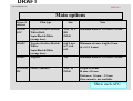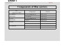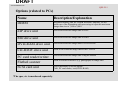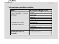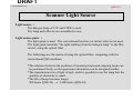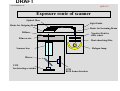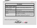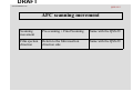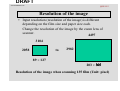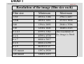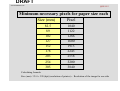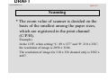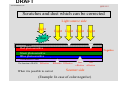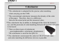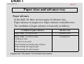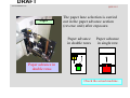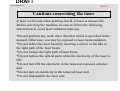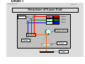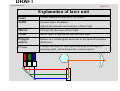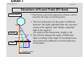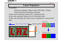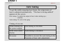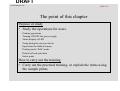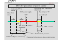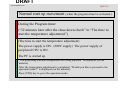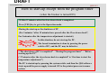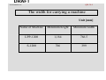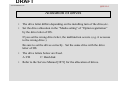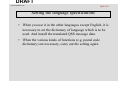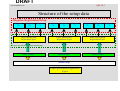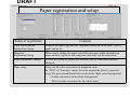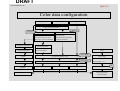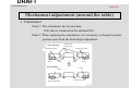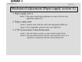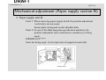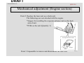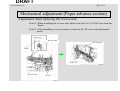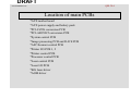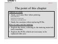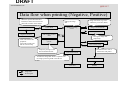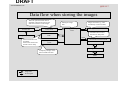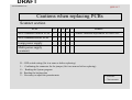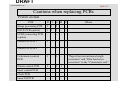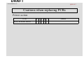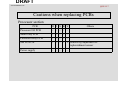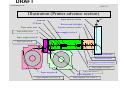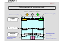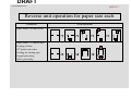
1
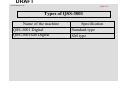
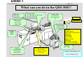
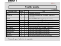
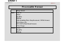
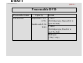
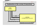
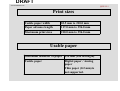
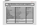
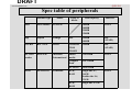
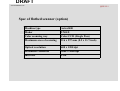
DRAFT QSS-30 www.minilablaser.com QSS-30 Training Materials Published: 2001.08 [Second edition] Technical Training Department Technical Support Group DRAFT www.minilablaser.com QSS-30-1 Chapter 1 Specifications DRAFT www.minilablaser.com QSS-30-1 The point of this chapter Purpose of study • Study the specifications of the QSS-30. Processing capacity Main options Spec of PC How to carry out the training • Explain, using the Training material. • Refer to Specification Manual for the details. DRAFT www.minilablaser.com QSS-30-1 Concept Full digital mini-lab system which outputs from scanning image to the photographic paper by digital signal. This is the first digital mini-lab with the laser engine installed at Noritsu. The film is scanned by the S-1200 (Single Film Scanner),the image data is transferred to LPP-1200 (Laser Printer Processor) through LVDS cable, and prints are made. The QSS-30 can process up to 210 mm paper width. This is the succeeded machine with the QSS-26. QSS-3001Digital : 89 x 127 1160 prints / hour 89 x 127 620 prints / hour Digital camera/media DRAFT www.minilablaser.com QSS-30-1 Types of QSS-3001 Name of the machine QSS-3001 Digital QSS-3001SM Digital Specification Standard type SM type DRAFT QSS-30-1 www.minilablaser.com What can you do in the QSS-3001? Reflective FB scanner Storage media FD, CD-ROM, CD-R,CD-RW, MO, ZIP, DVD-RW Digital camera PC card Smart media Compact flash Print Out put Index prints Negative films 135 (F/H/P/HD) IX240 120,110 ID Prints Package Prints Post Cards (Greeting Cards) Calendars Multi Prints Letter Prints Business Cards WB Prints Label index for media Contact Print Style Photos Compact archive system Out put Network Correspondence File sharing Mail function Positive films 135 roll/mount IX240 roll/mount 120 Writing the image data HD, FD, MO ZIP, CD-R, CD-R/W, DVD-RAM B/w films 135 120 Time schedule of new functions DRAFT www.minilablaser.com QSS-30-1 Usable media x = available Input Output FD x x CD-ROM x CD-R x x The CD-R/RW drive (option) is necessary. CD-RW x x The CD-R/RW drive (option) is necessary. MO x x The MO drive (option) is necessary. ZIP x x The ZIP drive (option) is necessary. DVD-RAM x x The DVD-RAM drive (option) is necessary. Compact flash x x The card reader (option) is necessary. Smart media x x The card reader (option) is necessary. PC card x x The card reader (option) is necessary. Reflective x Types of media Note Standard equipment CD-ROM (standard) or CD-R/RW (option) is necessary. The flatbed scanner (option) is necessary. *Explain the spec of each drive, etc. separately. DRAFT www.minilablaser.com QSS-30-1 Processable Format Image format Input Exif 1.0 JPEG FlashPix Bitmap PSD (including Photo Shop Document, CMYK Format) PCD (Photo CD) PCX, DCX (Paint Brush Format) TGA (Targa) Output JPEG FlashPix Bitmap DRAFT www.minilablaser.com QSS-30-1 Processable DVD Processable format DVD-RAM Capacity Single side 2.6G 4.7G Double side 5.2G 9.4G Format TYPE1 (Cartridge-type, Impossible to eject the disk) TYPE2 (Cartridge-type, Possible to eject the disk) Disk-type (“Play” only) DRAFT www.minilablaser.com QSS-30-1 Main options Types of carriers Film type Size Note 135/240 AFC Negative/Positive/Black& White/(Roll) Sepia/Black&White (orange base) 135F, H, P, HD IX240 Minimum number of frames:2-frame 120AFC Negative/Positive/Black& White/ Sepia/Black&White (orange base) 6x4.5, 6x6, 6x7, 6x8, 6x9 Minimum advance length:43 mm (6 x 4.5 1 frame) 110AFC Negative 110 Minimum number of frames:3-frame 135/240M MC Positive (mount) 135F, H, IX240 Length of mount 50 mm x 50 mm Thickness: 1.0 mm – 3.2 mm Glass mount is not available. Show each AFC. DRAFT QSS-30-1 www.minilablaser.com Components of film carriers AFC (only for S-1200) Components Part No. 135/240AFC Z809328-01 S-1200 compatible kit Z809335-01 135/240AFC Z809292-01 120AFC Z809329-01 S-1200 compatible kit Z809336-01 120AFC Z809295-01 110AFC 135/240MMC DRAFT www.minilablaser.com QSS-30-1 Options (related to PCs) Name DIMM Description/Explanation ZIP drive unit Unit to save/read the image data to a ZIP MO drive unit Unit to save/read the image data to a MO DVD-RAM drive unit Unit to save/read the image data to a DVD-RAM CD-R/RW drive unit Used to save/read the image data to the CD-R/W PC card reader/writer Flatbed scanner SCSI card unit Unit to save/read the image data of digital camera *The spec, etc is mentioned separately. Extended memory unit for 256MB Personal Computer, for the stable use of the Photoshop with processing to input the maximum image data size to 7,400 x 5,000. Used to read the reflective (e.g. photograph) as image data Unit is necessary to set the option (MO, PC card reader, /raid, DVD-RAM) DRAFT www.minilablaser.com QSS-30-1 Package contents of image edition Name Description/Explanation Card/Calendar Creation Software Calendars Post card prints Business Cards Frame Prints Letter printing Card Prints Multi-Frame Print Creation Software Multi-frame Prints Album Prints Package Prints Contact Print Style Photos ID Photos Red Eye Removal Software Red eye removal function DRAFT www.minilablaser.com QSS-30-1 Others Name Description/Explanation Digital ICE Used to remove scratches, etc. from image in negative or positive which is scanned by the built-in scanner. (Software and sticker) CVP, Ribbon cassette The ribbon cassette is compatible with the QSS-28, 29. Monitor hood This is compatible with the QSS-28, 29. Pricing unit Used to calculate prices and issue statements automatically Film cleaner kit Used to remove shut after the film scanning by AFC. Cleaner stand Used to put cleaner on the stand when processing film of 120, 110. Flatbed scanner desk Used to put flatbed scanner on the stand. Double magazine unit Used to change from shingle magazine to double magazine. 120AFC usable kit Used to add DIMM256MB for image processing PCB (total: 2) when processing 120 films. Scanner communicated kit (8m) Used to communicate from S-1200 to PP-1200. (factory option) DRAFT www.minilablaser.com QSS-30-1 Magazine Standard magazine Compatible between Normal and Kodak specification. (Carry out the unit replacement only as it is already adjusted.) QL magazine For QL paper (Carry out the unit replacement only as it is already adjusted.) The core unit is different from the standard magazine. Point 1: The magazine is only for QSS-30. Point 2: It is impossible to use the QSS-26 magazine by modifying it. It is possible to make a print with the QSS-26 magazine, but the zigzagging may occur. DRAFT www.minilablaser.com QSS-30-1 Explanation of the system (Connection) S1200 (Scanner) Power supply Cable (200V) Power supply Cable (200V) LPP1200 (LAZER Printer Processor) LVDS Cable Optical fiber cable (ARCNET) Single-phase tow-wire system 200V DRAFT www.minilablaser.com QSS-30-1 Print sizes Usable paper width 82.5 mm to 210.0 mm Paper advance length 117.0 mm to 356.0 mm Maximum print sizes 210.0 mm to 356.0 mm Usable paper Maximum diameter of paper 250 mm (180 m length) Usable paper Digital paper / Analog paper Thin paper (0.2 mm) is not supported. DRAFT www.minilablaser.com QSS-30-1 Specifications of personal computers PC spec table Product name Specifications CPU Pentium III 733MHz Mother board FB5-LN-12 Memory RIC-S133-256A 256MB PC133 3.5FDD YD-702D-6238D 2 modes Hard disk LCT20 20GB 20GB CD-ROM drive CR-594-B 48x Keyboard (Japanese) FKB8724-501 Keyboard (English) FKB8725-401 Mouse Mouse Port Compatible Mouse 2.2A OS Windows 2000 professional SP1.COA DRAFT QSS-30-1 www.minilablaser.com Spec table of peripherals Machine type Maker MO MCE3064SS FUJITSU Zip Zip250 Iomega CD-RW RW7125A PC card reader PCD-47B DVD LF-D291NS Types of media Data capacity Interface 640MB 540MB 230MB 128MB SCSI-2 ZIP 250MB 100MB IDE (ATAPI) Ricoh CD-ROM CD-R CD-RW 650MB IDE (ATAPI) Microtek International Smart media 2 to 64MB SCSI-2 Compact flash 4 to 128MB PCMCIA 10 to 85MB DVDRAM Single side 4.7, 2.6GB Double side 9.4, 5.2GB DVDROM Single side 4.7GB Panasonic SCSI-2 DRAFT www.minilablaser.com QSS-30-1 Spec of flatbed scanner (option) Machine type Astra3400 Maker UMAX Color scanning way Color CCD (Single Pass) Maximum area of scanning 216 x 297 mm (8.5 x 11.7-inch) Optical resolution 600 x 1200 dpi Maximum resolution 9600 x 9600 dpi Interface USB DRAFT www.minilablaser.com QSS-30-2 Chapter 2 Outline of the system DRAFT www.minilablaser.com QSS-30-2 The point of this chapter Purpose of study • Explain the outline of the system for the QSS-30. Scanner, Laser Processable media, Image size, Paper size Digital-ICE, Paper advance system How to carry out the training • Explain the items referring to the training materials and using the actual machine. DRAFT www.minilablaser.com QSS-30-2 Scanner Light Source Light source : The halogen lamp of 15V and 150W is used. The lamp and reflector are assembled in one. Light source parts : The light guide is used. The conventional lens box (or mirror tube) is not used. The light guide transmits “the light emitting from the halogen lamp” to the film carrier, using the optical fiber. The followings are the merits of using the optical fiber, comparing with the conventional QSS machines. *The relations between the positions of incoming beam and outgoing beam can be positioned freely, so the appearance dimension can be designed smaller. *The transmission rate of light is high, and it is possible to use the lamp that the quantity of electricity is small. *The life of lamp becomes longer. 900 hours (QSS-29) → 2,400 hours (QSS-30) DRAFT www.minilablaser.com QSS-30-2 Exposure route of scanner Optical fiber Light Guide Route for Outgoing Beam Route for Incoming Beam Diffuser Negative/Positive filter wheel Film carrier Heat absorbing filter Scanner lens Halogen lamp Mirror CCD for detecting scratches CCD RGB frame detection DRAFT www.minilablaser.com QSS-30-2 Scanner Image capture method Optical resolution (Main or the CCD line) Input the one line image with line CCD. Scan pitch (Sub scanning) Film is moved. Scan RGB each with line CCD (5,000 pixels). CCD Others ISL filter*1 is available. Automatic dust and scratch removal for films is available. (Digital ICE) (option)*2 Sticker for permission of use QSS *1 *2 DRAFT www.minilablaser.com QSS-30-2 AFC scanning movement Scanning movement Pre-scanning + Final Scanning Same with the QSS-29 Film ejection direction Return to the film insertion direction side Same with the QSS-29 DRAFT www.minilablaser.com QSS-30-2 Resolution of the image • Input resolution (resolution of the image) is different depending on the film size and paper size each. Change the resolution of the image by the zoom lens of scanner. 4497 3104 2058 to 2982 89 × 127 203 × 305 Resolution of the image when scanning 135 film (Unit: pixel) DRAFT www.minilablaser.com QSS-30-2 Resolution of the image (film size each) Film size Minimum Maximum 135F 2058 x 3104 2982 x 4497 135H 2058 x 1451 2574 x 1834 240 1394 x 2093 2046 x 3596 110 1250 x 1645 1640 x 2145 6 x 4.5 4599 x 3362 6x6 4599 x 4530 The resolution of the image is fixed. 6x7 4666 x 5617 6x8 4666 x 6290 6x9 4620 x 6727 135 mount 1397 x 2939 240 mount 1260 x 2215 DRAFT www.minilablaser.com QSS-30-2 Minimum necessary pixels for paper size each Size (mm) 82.5 89 102 127 152 178 203 254 305 Pixel 1040 1122 1286 1600 1915 2243 2558 3200 3840 Calculating formula Size (mm) / 25.4 × 320 (dpi) (resolution of printer) = Resolution of the image for one side DRAFT www.minilablaser.com QSS-30-2 Scanning * The zoom value of scanner is decided on the basis of the smallest among the paper sizes, which are registered in the print channel (C/P/H). Example) In the 135F, when setting “C: 89 x 127” and “P: 210 x 356”, the resolution of image is 2058 x 3104. The resolution of image for 210 x 356 channel only is 2982 x 4497. DRAFT www.minilablaser.com QSS-30-2 Print channel and scanning In the case of interspersed channel (3R and maximum paper size) 1726 3104 1145 2058 145 89 × 127 % 4505 In the case of CH for maximum paper only 4497 100.1% 2987 2982 Input data Output data 210 × 356 DRAFT www.minilablaser.com QSS-30-2 Pre-scanning Film sizes Resolution 135F C/HD/P 257 x 388 135H 257 x 181 240C/HD/P 252 x 442 110 312 x 411 6 x 4.5 286 x 210 6x6 286 x 283 6x7 291 x 351 6x8 291 x 393 6x9 291 x 424 135 mount (F/HD/P) 239 x 367 135 mount (H) 239 x 156 240 mount 157 x 276 DRAFT www.minilablaser.com QSS-30-2 Digital ICE Original image Film RGB scanning data Lens Mirror CCD for detecting RGB images The data with scratch Corrected image CCD for detecting scratches The technology to make the images without scratch, dust, etc. In addition to the CCD which takes the color information of RGB, the another CCD is added. It detects the dust, scratch, etc. on the film. This corrects the scanned image information. DRAFT www.minilablaser.com QSS-30-2 Corrections by Digital ICE QSS-29, 28 Correct function The image is corrected automatically by Digital ICE (option) Processing ability The processing ability does not change even when this is functioned. The conditions for functioning the Digital ICE QSS-29 PCB, power supply Already attached when shipping from the factory Installing the software Reading the software of Digital ICE Registration in the mode Mark the check box in the “Operator selection” . DRAFT www.minilablaser.com QSS-30-2 Scratches and dust which can be corrected Light source side Light Light Light Light Light Dust Base Red photosensitive Green photosensitive Blue photosensitive Protective coat The function of D-ICE: Effective Negative Effective Effective When it is possible to correct Not Not effective effective Scanner side (Example: In case of color negative) DRAFT www.minilablaser.com QSS-30-2 Colorimeter * The colorimeter is adopted for the precise color matching when carrying out the CMS. * The conventional colorimeter measures the density of the color of the paper. Therefore, there is a difference between the actual print and the measured value. *This colorimeter has an ability to distinguish like from the human's eye, and the precision of color matching between the monitor and print is increased. * There are three types of colorimeter – spectrophotometer, colorimeter, densitometer. The colorimeter is used for the QSS-30. * The colorimeter can measure the color in CIE-XYZ/Lab value, and color matching for difference devices is possible. DRAFT www.minilablaser.com QSS-30-2 Paper sizes and advance way Paper advance In the QSS-30, there are two types of advance way. Paper advance in single row, Paper advance in double rows The condition of paper advance is basically as follows. Condition of paper advance Paper width : 102 mm or less Paper width : 117 mm or more Leading of order 50th print in one order When feeding the leading edge of paper When feeding the fogged paper When feeding the spliced paper Explain in the “Movements” for the details of movements. Advance way In double rows In single row DRAFT www.minilablaser.com QSS-30-2 Paper The paper lane selection is carried out in the paper advance section (reverse unit) after exposure. Paper advance in double rows Paper advance in single row Paper advance in double rows Check the actual machine. DRAFT www.minilablaser.com QSS-30-2 Laser Engine Laser: Abbreviation of Light Amplification by Stimulated Emission of Radiation In the QSS-30, the exposure method by Visible Radiation is employed. DRAFT www.minilablaser.com QSS-30-2 Cautions concerning the laser R laser is ON only when printing, but B, G laser is always ON. Before servicing the machine, be sure to follow the following instructions to avoid laser radiation exposure. *Do not perform any work other than that which is specified in the manual. Otherwise, you may be exposed to laser beam radiation. *Do not reflect the laser beam by inserting a mirror or the like in the light path of the laser beam. *Do not change the light path of laser beam. *Do not replace the optical parts while the electricity of the laser is ON. *Do not turn ON the electricity in the removed exposure advance unit. *Do not turn on electricity in the removed laser unit. *Do not disassemble the laser unit. DRAFT www.minilablaser.com QSS-30-2 Printer Exposure Engine Exposure way Output gradation Maximum exposure width Print resolution Line exposure method by the Laser engine 4096 gradation 216 mm (8.5-inch) 320 dpi (Optical resolution –Main or the CCD line-) × 640 dpi (Scan pitch –Sub Scanning-) Exposure speed 50.8 mm/sec Light source B laser, G laser, R laser DRAFT www.minilablaser.com QSS-30-2 Structure of Laser Unit Mirrors AOM R laser AOM G laser AOM B laser Polygon mirror Prism Fθ lens Paper DRAFT www.minilablaser.com QSS-30-2 Explanation of laser unit Laser Visible Radiation Laser for R, B, B each AOM Acousto-Optic Modulator Adjusts the strength and weakness of laser light. Mirror Changes the direction of laser light. Prism Mix R light, G light and B light into one light. Polygon mirror Rotates in a certain speed and scans in the Optical resolution (Main line). Fθ lens Changes the angle of laser light according to the angle of incoming light, and maintains the constant speed. DRAFT www.minilablaser.com QSS-30-2 Structure of Laser Unit (AOM) * AOM controls the strength of laser light. 1. When the voltage is not turned ON to AOM, the incoming laser beam passes through as it is. (0-th order light) 2. When turning ON the high frequency voltage, the ultrasonic waves occurs, and the diffracted light which is separated from 0-th order light occurs. (Diffracted light of first order) 3. Change the rate of 0-th order light and the diffracted light of first order by changing the high frequency voltage on AOM, and control the strength of light (diffracted light of first order) to be used for exposure. Diffracted light of first order Laser AOM Exposure 0-th order light NOTE The direct light is called 0-th order light. DRAFT www.minilablaser.com QSS-30-2 Structure of Laser Unit (Fθ lens) Polygon mirror Fθ lens * The Fθ lens corrects the dispersion of linear velocity caused by the angle of incoming beam. θθ Paper A A 1. The travel (distance) on the paper is different between “the light outputted from the exposure center at the angle θ” and “further outputted light at the angle θ” (As shown in the illustration, length A, B) 2. The Fθ lens changes the angle of diffracted light according to the angle of incoming beam, and corrects the difference of travel (distance) on the paper. B Exposure center DRAFT www.minilablaser.com QSS-30-2 Laser Exposure Resolution Optical resolution (Main or the CCD line): 320 dpi Scan pitch (Sub Scanning): 640 dpi In the main scanning: Expose for 1 dot pitch each In the sub scanning: Expose for 0.5 dot pitch each In the sub scanning, the same color is exposed in 2 consecutive dots. Image data Paper advance direction Exposure position Exposure image DRAFT www.minilablaser.com QSS-30-2 Auto tuning To get the stable outgoing laser beam, the temperature of laser is adjusted automatically. ”The laser is being stabled” appears on the screen. Fine tuning: To stable the output of laser when starting up a machine Auto tuning: To correct the aging Timing of execute When turning ON the power supply In the close down checks Occasion Fine tuning is executed. Auto tuning is executed. Possible to execute the auto tuning in the Function of laser unit adjustment. DRAFT www.minilablaser.com QSS-30-3 Chapter 3 Operations DRAFT www.minilablaser.com QSS-30-3 The point of this chapter Purpose of study • Study the operations for users. Printing operations Turning ON/OFF the power supply Status display of LED Setup during the start-up checks Input from the flatbed scanner Printing in the “Edit” mode Details of back print data Index prints How to carry out the training • Carry out the practical training, or explain the items using the sample prints. DRAFT www.minilablaser.com QSS-30-3 Setup during the start-up checks Daily setup Weekly setup Monthly setup Execute once a day for each paper type to be used. Correct the temporary aging of exposure engine, light source and processing solution. Make a 18-step test print. Execute once a week. This is displayed instead of the daily setup. After carrying out the daily setup, carry out the printer profile calibration to correct the temporary aging of data characteristics for each printer. (Execute it for each paper type). Make test prints. 18-step setup prints (daily setup) 16-step setup prints (printer profiles) Carry out the uniformity (calibrator). Execute once a month. After completing the daily setup and weekly setup, execute it. Carry out the monitor profile calibration to correct the temporary aging of monitor. Adjust the monitor again. DRAFT www.minilablaser.com QSS-30-3 Daily setup flow Make a test print (18-step setup print) When the light source upgrading (auto) (135 lane) is carried out during the program timer Light source upgrading (135 lane) Calorimeter calibration Measure a test print. Registration When the light source upgrading (auto) (135 lane) is not carried out during the program timer DRAFT www.minilablaser.com QSS-30-3 Weekly setup flow Daily setup is completed. Make a test print. (16-step setup print) Measure a test print. Update the Printer profile data. Registration DRAFT www.minilablaser.com QSS-30-3 Monthly setup flow Daily or weekly setup is completed. Monitor color and temperature adjustment Monitor brightness/contrast adjustment Monitor profile calibration Updating the monitor profile DRAFT www.minilablaser.com QSS-30-3 Explanation of operations * Explain with the actual machine. - Start-up checks - Explanation of [ORDER] display Output to HD Input from CT-1 Explanation of HELP - Explanation of [MENU] display - Explanation of [HELP] * Explanation of printing operations - Carry out the practical training. DRAFT www.minilablaser.com QSS-30-3 Explanation of modes • Paper fitting Cut/Real Size/Overall • Correction of JUDGE images • Pass setting of HD storing • NCE mode CH export data DRAFT QSS-30-3 www.minilablaser.com NCE mode It is possible to control the output of laser and correct the color (Cyan, Yellow, etc.) around the letter by inputting the correction value in the “NCE” mode. (e.g.) Outline characters on the black background The part around black letter on the white background However, the trend of color changes depending on various conditions (Font type, Font size, condition of processing solution, etc.). So, even if you make a perfect correction to a condition, the same quality cannot be gotten for the other conditions. Description******************************** Light Light amount of laser is not constant in one dot, not like the ideal amount waveform (illustration). The light amount is maximum at the center, and it is getting smaller gradually as it is close toward the radial rake. Therefore, the low density part appears on the half-tone dot meshing part (illustration), and this part may be colored Cyan, Yellow, etc. depending on the chromogenic property of paper. It is not noticeable in the consecutive color. But, it is noticeable in the following scene. The scene that the density difference appears clearly, especially outline characters on the black ground, black letter around the white background. Perfect waveform Laser beam 1 dot DRAFT www.minilablaser.com QSS-30-3 ON/OFF procedure of power supply Shutdown of PC is started 200V power supply Close down checks OFF 12 minutes The time to start temperature adjustment The startup of PC is completed. 5 minutes 20 minutes 5分 The shutdown of PC is completed. The startup of PC is started. The PC is being processed. Wait for cooling the scanner lamp Preparation for the shutdown of each printer section DRAFT www.minilablaser.com QSS-30-3 Normal shutdown movement (Close-down check is completed.) Scanner lamp is OFF “Program timer is activating.” is displayed (on the monitor). The PC is shutdown. (12 minutes later after the close-down check) The power supply (200V supply) is OFF. (32 minutes later after the closedown check) The power supply of peripheral CPU and cooling fan is OFF. DRAFT www.minilablaser.com QSS-30-3 Normal start up movement (when the program timer is activated.) During the Program timer (“32 minutes later after the close down check” to “The time to start the temperature adjustment”) (The time to start the temperature adjustment) The power supply is ON. (200V supply) The power supply of peripheral CPU is ON. The PC is started up. “The processing solution temperatures are being adjusted” is displayed (on the monitor). After the temperature adjustment is completed, “Would you like to proceed to the operation mode?” is displayed (on the monitor). Press [YES] key to go to the operation mode. DRAFT www.minilablaser.com QSS-30-3 How to start-up except from the program timer (when the breaker is turned ON) •Within 12 minutes after the close down check is completed. Press [YES] key to got to the Operation mode. •During the start up or the shutdown of PC (For 5 minutes “after 12 minutes have passed after the Close down check”, For 5 minutes after the temperature adjustment is started.) In this situation, do not start-up the PC. Important The forced termination is done by pressing the power switch of PC, and the PC may be defective. •“The shut down of PC is completed” – “During the program timer” – “Before starting up the PC” (“17 minutes after the close down check is completed” to “the time to start the temperature adjustment”) The PC is started-up by pressing the system switch, and then the QSS software starts up and the power supply is turned ON to the printer/processor/scanner section. DRAFT www.minilablaser.com QSS-30-3 How to start-up after the breaker is turned OFF * Turn ON the breaker, press the power switch of PC and the PC starts up. 3 minutes later, the power supply of printer/processor/scanner section is turned ON. DRAFT www.minilablaser.com QSS-30-3 How to turn OFF the breaker * How to turn OFF the breaker after the close down check (e.g. When you do not use the function of the program timer) When 12 minutes have passed after the close down check is completed, the shutdown of PC is started. Confirm that the power LED is turned OFF, and turn OFF the breaker. * When turning the breaker OFF in the case of troubleshooting, etc, press [F] key in the “Close down check” mode and select “Turn OFF the power supply”. After confirming that the power LED of PC is OFF, turn OFF the breaker. Caution *Turn OFF the scanner lamp, and wait for 10 minutes or more. After that, turn OFF the breaker. The lamp may be damaged. DRAFT www.minilablaser.com QSS-30-3 How to turn OFF the breaker when the PC is locked 1. Check the LED of HD. When the LED of HD is lighting or blinking, the HD is activating. If turning the power supply OFF when the HD is activating, the HD may be damaged. Wait until the LED is turned OFF. 2. Turn OFF the power supply of PC by pressing the SW of PC for 4 seconds or more. When the power supply of PC is not turned OFF even after pressing the system switch for 4 seconds or more, restart the system by pressing the reset switch for 4 seconds. 3. Turn OFF the breaker of processor. Wait for approx. 10 seconds after turning the breaker OFF. And then turn the breaker ON. DRAFT www.minilablaser.com QSS-30-3 How to turn OFF the breaker in an emergency * When turning OFF the breaker in an emergency, turn OFF the breaker of the processor. The UPS is activated and the PC is shutdown. The time for the PC shutdown changes depending on the status of PC. (several minutes to 20 minutes) DRAFT www.minilablaser.com QSS-30-3 Status display of AFC Ready lamp Condition of display Lighting Green Possible to process films (You can insert a film.) Blinking Film is being processed. (You cannot inset a film). Green Blinking Red Impossible to process films (You cannot process a film.) *The error occurs. (You cannot process a film.) * The error occurs. (You cannot print.) Dark Impossible to process films (You cannot process a film.) *When the “Film” is not selected for “Image input” in the print channel setting. *During the start-up checks and close-down checks *During the program timer *When the message “Insert a film.” does not appear on the adjustment mode. *During the initial movement DRAFT www.minilablaser.com QSS-30-3 Details of the back print * Film and media except 240 NORITSU <12> 005 (X) FBS 12 (I) (K) (D) (E) (F) 284 15 +1+1+1+1 +30 AC01 Acs –10 Ach -10 AS02 SA200 GR10 RE01 SF02 FC01 XF02 R090 Z80 (J) (L) (M) (N) (O) (P) (Y) (Z) (Q) (R) (S) (T) * For 240 (TYPE1) BIRTHDAY EL25 MGhi FFn BVvh Alh PAc SUn CH1 LAB01 (A) (B) (C) 01.05.29 11:57A 001-001 (12) 284 005 15 +1+1+1+1 +30 (G) (H) (I) (J) (K) (L) (M) * For 240 (TYPE2) BIRTHDAY EL25 MGhi FFn BVvh Alh PAc SUn CH1 (A) (B) 29/MAY/01 11:57A ID001-001 (12)FTPM LAB01 (G) (H) (I) (C) (D) (N) C CD 12 (D) (E) (F) *Digital correction data (Same with films except 240) (V) (W) DRAFT www.minilablaser.com QSS-30-3 Details of the back print * Editing BIRTHDAY 123 12 (A) (K)(D)(F) 284 15 〈CUSTOMERINFO.mdb 1234 (J) (L) (1) (2) * Back print data only for editing (1) File name for customer information (2) Customer number for customer information DRAFT www.minilablaser.com QSS-30-3 (A) Title (K) Print count (B) Camera information (L) Print channel (C) LAB ID (M) Color, density correction (YMCD) (D) Copyright mark (N) Scanner correction (E) Input medias (O) Auto contrast correction value (F) Template (P) Auto sharpness correction value (G) Date, Time (Q) Red-eye correction value 240 TYPE2: the month is displayed in 3 letters (English letter). (R) Soft focus correction value (S) Color conversion Color image: FC Monochrome: MoF Sepia: SeF (H) (I) (J) Film ID (FID) (T) Cross filter correction value 240TYPE2: ”ID” is displayed before the number. (V) Rotation angle of the image Frame number (W) Zoom and crop of the image 240TYPE2: FTPM or SERIES is displayed after the frame number. (X) Backprint (Y) Chroma correction (Z) Graininess repression correction Order number DRAFT www.minilablaser.com QSS-30-3 Index print sizes * Normal index prints Name Sizes 3HS 3R 3HD 3W 4R 4HD 5R 82.5 x 158 89 X 127 89 x 158 89 x 178 102 x 152 102 x 178 127 x 178 - - - 135/120/110 240 - Medias - - - - Name 6R 6HD 6W 8R 8HD Sizes 152 x 203 152 x 254 152 x 305 203 x 305 203 x 356 - - - 135/120/110 240 Medias : Available : Available with 29 frames or more : Not available - DRAFT www.minilablaser.com QSS-30-3 Types of index prints Normal index prints Make normal index prints. The data for displaying on the PJP mode is used. Label index prints Index print for the media case size of storage media No index print for smart media, PC card and compact flash Contact Print Style Photos Make Contact Print Style Photos. IX240 and medias are not supported. DRAFT www.minilablaser.com QSS-30-3 Background color for index prints *8 colors can be selected as a background color of an index print. 1. Gray 5. Orange 2. White 6. Green 3. Pink 7. Light blue 4. Yellow 8. Purple DRAFT www.minilablaser.com QSS-30-3 Label index prints Types of media Size Format FD MO Zip CD 89 x 114 89 x 117 97 x 120 120 x 120 6, 20, 35 6, 20, 35 6, 20, 35 80 (number of frames) Note The number of frames are switched automatically. The number of frames are switched automatically. The number of frames are switched automatically. The number of frames are fixed. DRAFT www.minilablaser.com QSS-30-3 Index print sizes for Contact Print Style Photos Paper sizes for 6-frame Name Paper width (minimum width) Paper advance length CP6_1 CP6_2 CP6_3 CP6_4 CP6_5 82.5 mm or more 82.5 mm or more 120 mm or more 165 mm or more 203 mm or more 228.6mm 228.6mm 228.6mm 228.6mm 228.6mm Paper sizes for 4-frame CP4_1 CP4_2 CP4_3 CP4_4 CP4_5 CP4_6 CP4_7 Paper width 82.5 mm or more 82.5 mm or more 120 mm or more 152 mm or more 152 mm or more 152 mm or more 152 mm or more Paper advance length 152 mm 152 mm 152 mm 152 mm 191 mm 227 mm 263 mm Name CP4_8 CP4_9 Paper width 152 mm or more 152 mm or more Paper advance length 300 mm 336 mm Name Size: When printing the paper to be used with the minimum necessary paper width. Only 135F is supported. DRAFT www.minilablaser.com QSS-30-3 Index print sizes for Contact Print Style Photos *Contact index prints CP4_1 CP6_1 CP4_8 CP6_3 DRAFT www.minilablaser.com QSS-30-3 Practical training • • • Explain the modes, checking the actual machine. Start up checks Explanation of ORDER screen Output to HD Input from CT-1 Input from compact archive • • Explanation of MENU screen Explanation of HELP screen • Explanation of printing operation Carry out the practical training. DRAFT QSS-30-4 www.minilablaser.com Chapter 4 Installation DRAFT QSS-30-4 www.minilablaser.com The point of this chapter Purpose of study • Study so that the trainees can install the QSS-30 (LPP-1200). The width for carrying a machine Outdrawing Required parts when installing a machine PC peripherals Setting the language specification How to carry out the training • The trainee will provide an oral explanation of the caution points, referring to “Installation Manual” and a machine. • Carry out the mechanical adjustment or installation of options in the other chapter. You do not carry out the practical training here. DRAFT QSS-30-4 www.minilablaser.com The width for carrying a machine Unit [mm] Name of Machine Minimum height Minimum width LPP-1200 1,184 766.5 S-1200 706 399 DRAFT QSS-30-4 www.minilablaser.com The space for installation In case of Single magazine Unit : mm 500 250 1650 2490 1385 In case of Dual magazine (197) 90 2559 00 15 Refer to Specification Manual for the details. IMPORTANT In the Specification manual, the back space is 90 mm or more. But, 190 mm or more is required to open/close the PC control unit. If there is enough space for installation, we recommend to leave 190 mm or more in the back side of machine. DRAFT QSS-30-4 www.minilablaser.com Close/Open the PC control unit (190 mm in the back side of machine) 1. PC control unit Point 1 : When opening/closing the PC control unit, be sure to set the stopper with the cover of PC control unit. Stopper G058054 DRAFT QSS-30-4 www.minilablaser.com Lifting a machine (LPP-1200) *Lift a machine with rope, as shown in the illustration. Caution *Place the support wood, referring to the “Indication of lifting the machine” manual. *Be careful so that the power is not applied on the table. Support wood Packing Angle DRAFT www.minilablaser.com QSS-30-4 Packing items (LPP-1200) Packing parts LPP-1200 main body Filter pipe Ribbon Cassette Chemical filter Mouse pad Filter case Assist jack-bolt Print conveyor unit 1 monitor Paper guide (print conveyor unit 2) Packing items (S-1200) 135/240 AFC Scanner lamp Film receiving box DRAFT www.minilablaser.com QSS-30-4 Packing items (accessories) Types Name Description INITIAL DATA 1 For Printer and Scanner Contains the adjustment data for each machine INITIAL DATA 2 For Processor One FD for processor section One FD for printer / scanner section SYSTEM PROGRAM Contains the necessary system files to activate the system PROFILE DATA Contains the profile data PC attachments Recovery CD for OS, Operator′s Manual, driver software, etc. Necessary for the maintenance of the PC attachments DRAFT QSS-30-4 www.minilablaser.com Packing items (Sample prints) Paper supply A Paper supply B Mechanical adjustment Check the zigzagging of paper supply unit A and B. Exposure image correction Exposure image correction Exposure zoom rate correction Exposure timing correction Exposure center correction Exposure position adjustment Check that the “dots in each color of laser” overlap correctly. Exposure center correction (Master) Exposure position fine adjustment Check that the “dots in each color of laser” on both sides of print overlap correctly. DRAFT www.minilablaser.com QSS-30-4 Practical training * Install a machine, referring to the Installation Manual. DRAFT QSS-30-4 www.minilablaser.com Location of PC peripherals Mother board FD MO Card reader ZIP DVD-RAM HD CD-ROM · R/RW DRAFT www.minilablaser.com QSS-30-4 SCSI ID No. Drive MO CD-ROM, CD-R/RW PC card Smart media Compact flash None DVD-RAM SCSI board ZIP HD FD Flatbed scanner ID No. 0 2 3 4 5 6 7 - Note Secondary IDE Not in use Primary IDE Secondary IDE FD connector USB DRAFT www.minilablaser.com QSS-30-4 Cautions when attaching the PC peripherals at site = necessary Drive ZIP MO CD-R/RW DVD-RAM Card reader Flatbed scanner Installing the drives Setting and Check of the SCSI ID and IDE jumper switch DRAFT www.minilablaser.com QSS-30-4 Allocation of drives • The drive letter differs depending on the installing turn of the drive,etc. • Set the drive allocation in the “Media setting” of “Option registration” by the drive letter of OS. If you set the wrong drive letter, the malfunction occurs. (e.g. it accesses to the wrong drive.) Be sure to set the drives correctly. Set the same drive with the drive letter of OS. • The drive letters below are fixed. A: FD C: Hard disk • Refer to the Service Manual [3871] for the allocation of drives. DRAFT www.minilablaser.com QSS-30-4 Setting the language specifications • When you use it in the other languages except English, it is necessary to set the dictionary of language which is to be used. And install the translated QSS message data. • When the various kinds of functions (e.g. postal code dictionary) are necessary, carry out the setting again. DRAFT www.minilablaser.com QSS-30-5 Chapter 5 Setup DRAFT www.minilablaser.com QSS-30-5 The point of this chapter Purpose of study • Study about the setup. Initial setup Monitor setup Paper specification registration Print channel setting Emulsion number change Scanner slope correction Outline of CMS Profile How to carry out the training • Carry out the practical training, or explain the items using the sample prints. DRAFT www.minilablaser.com QSS-30-5 Setup when installing a machine • There are two patterns of setup procedure when installing a machine to shorten the installing time. There are two procedures for the conditions below. During the temperature adjustment After the setup is completed. • It is not always necessarily to follow the procedure except for the setup when installing a machine. Refer to the Service Manual 7001, 7002. DRAFT www.minilablaser.com QSS-30-5 Details of the Initial setup 1. Setting the exposure amount (complete in one time) The difference of color characteristics (paper + solution + light amount) for each machine is corrected, and set the parameter to get the target density. 2. Paper gamma setup (maximum: 3 times) Using the data which was estimated in the step 1, make a 18-step test print and set the parameter to get the target density. 3. Printer profile calibration (complete in one time) Carry out the printer color matching for each paper type. This is carried out based on the profile data which has already been registered. DRAFT www.minilablaser.com QSS-30-5 Carry out the printer profile calibration for each paper specification. And carry out it also in the weekly setup. (for paper type each) This graph is the result of test print measurement. Three lines for B, G, R are displayed. It is ideal if all of three lines slant at the angle of 45°. This is the standard for checking the tendency of calibrated data. 4. Updating the AOM data (once) Adjust the gain of light source amount outputted from the laser. Update the characteristic data of AOM bias. NOTE Tester print: 18-step setup print (number of prints: 3) DRAFT www.minilablaser.com QSS-30-5 Setup flow Explain the setup flow when carrying out the installation. (e.g.) Prepared paper types Initial setup Paper type 1 : EDGE8 Paper type 2 : ROYAL8 Paper type 3 : Digital 3 Color Paper Paper Specification/Registration setup 89mm 127mm 102mm 152mm 89mm 102mm Magazine Registration setup DRAFT www.minilablaser.com QSS-30-5 Monitor setup 1. Monitor brightness adjustment * Color and temperature setting (6500K) * Contrast adjustment * Brightness setting Adjust it, referring to the Operator′s Manual of the display monitor. Adjust the color of the monitor here. 2. Monitor profile calibration DRAFT www.minilablaser.com QSS-30-5 Monitor setup 3. Monitor gamma correction The difference occurs between the color of print and that of monitor, depending on the light source of the place where you work. Improve the precision of color matching by setting the color difference freely. Make a test print, compare the color chart with the monitor and adjust it. DRAFT www.minilablaser.com QSS-30-5 Comparison of the scanner slope correction for films Corrections in the QSS-29 Film type Negative/Positive 135F, P, H, HD, 110, 240 6 x 4.5, 6 x 6, 6 x 7, 6 x 8, 6 x 9 Slope Master, Reference + DX U.N.O Correct, checking the images. How to input Input the value. Balance memory shift is not available Other corrections Carry out the contrast and saturation adjustment, checking the images. Corrections in the QSS-30 DRAFT QSS-30-5 www.minilablaser.com Initial setup (Practical training) * Carry out the initial setup. Initial setup Paper Specification/Registration Setup Magazine Registration Setup Monitor setup Making print channels Making print channels DRAFT QSS-30-5 www.minilablaser.com Structure of the setup data Magazine Registration/Setup Magazine (1) Magazine (2) Magazine # Paper Specification Registration/Type1 Magazine (1) Magazine (2) Magazine # Magazine (1) Magazine (2) Paper Specification Registration/Type2 Paper Specification Registration/Type3 Daily Setup 2 Daily Setup 3 Paper Specification Registration/Setup Daily Setup 1 Initial Setup Paper specification Registration Type1 Magazine # DRAFT QSS-30-5 www.minilablaser.com Paper registration and setup Kinds of registration Contents Paper Specification Registration/Setup Register the paper type and the magazine which are to be used. Up to 3 types can be set. Magazine Registration/Setup When newly adding the paper with different paper width and different paper surface, register a new magazine and carry out the correction. Emulsion number change Correct this when the paper specification and the emulsion number is changed. Paper setup Carry out the color correction for magazine each. In “NCE” of “Function” mode, the color around the letter is corrected. (e.g.) The part around black letter on the white (light-color) background Outline characters on the black background. This is not the correction for the whole print. DRAFT www.minilablaser.com QSS-30-5 Emulsion number change You can check the setup status which is used for emulsion number change. “OK” or “-” is displayed. The emulsion number change is possible when “OK” is displayed for the paper setup or magazine registration. In the other cases, set it so that “OK” is displayed. After that, carry out the emulsion number change. Sign Setup Setup OK Magazine Registration - Magazine Registration OK -- [Paper Specification Registration Setup] has never been carried out or has not been completed yet. [Paper Specification Registration Setup] has been completed successfully. Not to be registered in the [Magazine which is to be used for the setup]. Only [Magazine Registration] is carried out. But, [Magazine Registration Setup] has never been carried out or has not been completed yet. Not to be registered in the [Magazine which is to be used for the setup]. Only [Magazine Registration] is carried out. And, [Magazine Registration Setup] has been completed successfully. Both of [Magazine which is to be used for the setup] and [Magazine Registration] are not be carried out. DRAFT www.minilablaser.com QSS-30-5 Color data configuration Negative films Positive films Storage media Light source control data U, N, O U, N, O Negative slope correction Scanner slope (for master and size each) DX slope, contrast, saturation Brightness adjustment Contrast adjustment Positive slope correction Scanner slope (for master and size each) contrast, saturation Scanner parameter Parameter 1, 2, 3 Service parameter Print N (C, H, P) Profile OO Channel balance value Laser setup Profile data N (C,H, P) Gamma table 01 to 99 Channel balance value Paper gamma 1, 2, 3 N Monitor Storage media Negative key change ratio Positive key change ratio Media key change ratio Paper setup Paper temperature correction Rate DRAFT www.minilablaser.com QSS-30-5 DSA data configuration DSA PJP DSA master data Negative Contrast (Highlight, Shadow, Whole), Sharpness, Saturation, Graininess repression Positive Contrast (Highlight, Shadow, Whole), Sharpness, Saturation, Graininess repression Type 1, 2, 3 Media (Digital camera) Contrast (Whole), Sharpness, Saturation Type 1, 2, 3 Media (Standard media) Contrast (Whole), Sharpness, Saturation FB scanner Contrast (Whole), Sharpness, Saturation Negative Type 1, 2, 3 Positive Type 1, 2, 3 Media (Digital camera) Type 1, 2, 3 Media (Standard media) FB scanner DSA 00 print channel Negative Print size C, P, H Positive Print size C, P, H Media (Digital camera) Print size C, P, H Media (Standard media) Print size C, P, H FB scanner Print size C, P, H DSA reprint DSA 01 to 99 print channel Negative Contrast (Highlight, Shadow, Whole), Sharpness, Saturation, Graininess repression Positive Contrast (Highlight, Shadow, Whole), Sharpness, Saturation, Graininess repression The limits of total value for each correction value are as follows. Negative Print size C, P, H Positive Print size C, P, H Media (Digital camera) Print size C, P, H Auto contrast (Shadow) : -10 to +10 Media (Standard media) Print size C, P, H Auto contrast (Highlight) : -10 to +10 FB scanner Print size C, P, H Each DSA correction value exists separately. On the DSA screen of PJP, the total correction value is displayed. And, you can also do the correction here. Auto contrast (The whole): -10 to +10 Auto sharpness : -10 to +10 Saturation : 50 to 200 Graininess Repression : 0 to 10 DRAFT QSS-30-5 www.minilablaser.com Outline of CMS CMS (Color Management) in the QSS is to transmit the color information correctly (Color Matching). Therefore, the beautiful color is expressed beautiful as it is, and the subdued color is expressed subdued as it is. It is not to correct the color and make the color beautiful. When outputting (image display or print) the same image data (RGB color space) with the different output device (monitor or printer), the expressed color is different by looking at. This is caused by the difference of expressional characteristics for color depending on the devices. Monitor Original data Printer R:255 G: 0 B: : 0 R:255 G: 0 B: : 0 R:255 G: 0 B: : 0 Bluish Red Red Subdued Red To clear the color difference, CMS (Color Management) (Color Matching) is executed. DRAFT QSS-30-5 www.minilablaser.com Outline of CMS Make a standard data (Lab color space) for CMS. The standard data is stored in the virtual space called “PCS” which is at the center of device. INPUT: Convert “RGB color space data which is inputted from the input device” into the “Lab color space data” thorough the scanner profile. OUTPUT: Convert “Lab color space data” into “RGB (or CMYK) color space data” through the monitor profile (or printer profile). Scanner FB scanner Monitor Printer R:255 G: 0 B: 0 R:225 G: 10 B: 20 R:255 G: 0 B: 10 C: 0 M: 87 Y: 99 K: 0 Red Scanner profile (Positive only) Red Scanner Profile (FB scanner) Red Monitor Profile PCS (Profile Connection Space) L:54 a:81 b:70 Printer Profile Red DRAFT QSS-30-5 www.minilablaser.com Scanner profile The scanner profile is stored in the following place. SCN_DIR (The place where the scanner profile is stored) File name Contents S0000100.nkp Profile data for Microtek ScanMaker X6 S0010000.nkp Profile data for Umax Astro 3400 S0990100.nkp Profile data for positive films Note Not in use DRAFT www.minilablaser.com QSS-30-5 Printer profile The profile data is stored in the following place. PRN_DIR (The place where the printer profile data and the printer calibration data is stored) File name Contents p010###00.nkp Printer Profile Basic data (The data which was registered when shipping from the factory.) p010###00.cal Printer Calibration Basic data (The data which was registered when shipping from the factory.) p110###00.nkp Printer profile data which is actually used Note Changes by the profile calibration (Weekly setup) The printer profile exists for type of processing solution each. “p110##00.nkp” is calculated and made by the measured value and basic data (p110##00.nkp, p010##00.cal) in the “Paper Specification Registration/Setup”. DRAFT www.minilablaser.com QSS-30-5 Monitor profile The printer profile is stored in the following place. MON_DIR (The place where the monitor profile data and the monitor gamma adjustment data is stored) File name Contents Note m0010000.nkp Monitor Profile Basic data (The data which was registered when shipping from the factory.) Basic data which is set for type of monitor (Maker, Lot) m1010000.nkp Monitor Profile Basic data (The data which was registered when shipping from the factory.) Initial data which is measured by the colorimeter (Contains in the profile CD) m2010000.nkp Monitor profile which is actually used. Changes by the profile calibration (Monthly setup) DRAFT www.minilablaser.com QSS-30-6 Chapter 6 Mechanical adjustment DRAFT www.minilablaser.com QSS-30-6 The point of this chapter Purpose of study • Study about the printer mechanical adjustment. 135/240AFC Scanner section Paper advance section How to carry out the training • Carry out the practical training mainly and explain the cautions, referring to the materials. DRAFT www.minilablaser.com QSS-30-6 Removing the unit (Practical training) * Remove and attach the scanner. - Swing and Tilt Adjustment - Light axis adjustment - Light source registration - Focus adjustment DRAFT www.minilablaser.com QSS-30-6 Removing each unit (Practical training) * MMC - Position adjustment of mount carrier - Position adjustment of AF emission sensor - Position adjustment of AF detection sensor * Colorimeter unit - Remove the colorimeter unit/Replace the calibration plate - Position change and Head height adjustment of colorimeter unit * Paper supply section A - Remove paper supply unit A. - Replace the paper cutter / Right angle adjustment - Paper hold timing adjustment of arms - Pressure adjustment of CVP DRAFT www.minilablaser.com QSS-30-6 Removing each unit (Practical training) * Paper supply section B - Remove the paper supply unit / Position adjustment * Exposure advance unit - Remove the exposure advance unit. Be careful because the exposure advance unit may drop from the stopper. * Engine section - Remove the laser unit. (including the PC control unit) * Paper advance section - Remove the paper advance unit. - Standard adjustment of paper advance unit - Remove the processor insertion unit. DRAFT www.minilablaser.com QSS-30-6 Mechanical adjustment (Film carrier section) 1. AFC Point 1: In some of the sensors, only connector section itself can be replaced. The other sensor should be replaced as a whole of sensor PCB. Point 2: After replacing the AFC, the AFC focus adjustment for each magnification is necessary for each AFC to be used. 2. 135/240MMC Point 1: Explain the position adjustment of AF sensor. DRAFT www.minilablaser.com QSS-30-6 Mechanical adjustment (Scanner section) 1. Scanner unit Point 1: Impossible to disassemble (If you disassemble it, it is out of warranty.) Point 2: Compatible with the scanner unit of QSS-28/29 DRAFT www.minilablaser.com QSS-30-6 Mechanical adjustment (around the table) 1. Colorimeter Point 1: The colorimeter has its own data. (The data is contained in the attached FD.) Point 2: When replacing the colorimeter, it is necessary to change the plate position and check the head height adjustment. When delivering Positioning points Positioning points Screw Calorimeter advance unit Plates Plates Screw When installing Screw Positioning points Screw Positioning points DRAFT www.minilablaser.com QSS-30-6 Mechanical adjustment (Paper supply section A) 1. Paper supply unit A Point 1: The paper hold timing adjustment is same with the Arm adjustment (QSS-29). 2. Paper cutter unit Point 1: Almost same with the cutter unit adjustment (QSS-26) Point 2: Not compatible with the cutter unit (QSS-26) 3. CVP (Correction Value Print) unit Point 1: The ink ribbon cassette is same with the QSS-28/29. Point 2: The special ink which will not stick around is used. It is improved, comparing with the conventional ones. DRAFT www.minilablaser.com QSS-30-6 Mechanical adjustment (Paper supply section B) 1. Paper supply section B Point 1: When shipping from the factory, paper supply section is assembled with the machine main body. (Both of domestic and overseas) Point 2: Possible to modify the machine from Single-magazine specification to Dual magazine specification. DRAFT www.minilablaser.com QSS-30-6 Mechanical adjustment (Paper supply section B) 2. Paper supply unit B Point 1: When removing paper supply unit B, the position adjustment tools below are necessary. Spacer plate, Hexagonal socket shoulder bolts Point 2: In case of the Dual magazine-specification machines, the position adjustment tool is attached to a machine as a fixing angle. IMPORTANT***** Store the fixing angle by the right side of magazine mount (B). Storage place DRAFT www.minilablaser.com QSS-30-6 Mechanical adjustment (Exposure advance section) 1. Exposure advance unit Point 1: It is not necessary to adjust the pressure rollers of exposure advance unit and carry out the zigzagginng adjustment. (No mechanical adjustment) Point 2: The banding adjustment of exposure advance unit is same with the QSS-29, and the adjustment is possible in the “Mechanical adjustment” → “Paper pressure operation correction” mode. Point 3: It is necessary to clean the rollers of exposure advance unit every 6 month. (Use the specified cleaning sheet.) DRAFT www.minilablaser.com QSS-30-6 Mechanical adjustment (Engine section) 1. Laser unit Point 1: When removing the laser unit, it is necessary to adjust the position of laser unit using the positioning pins. Positioning pins Laser unit DRAFT www.minilablaser.com QSS-30-6 Mechanical adjustment (Engine section) Point 2: Replace the laser unit as a whole unit. The followings are not attached with the engine. *Stopper for installing the exposure advance unit on the back side of unit. *PCBs on the unit (Quantity: 3) Viewing from the back side Stopper Point 3: Impossible to remove and disassemble the laser unit. DRAFT QSS-30-6 www.minilablaser.com Mechanical adjustment (Paper advance section) Adjustment when replacing the reverse unit Point 1: When installing the reverse unit, adjust it so that it is 51.5±0.5 mm from the frame. Point 2: After installing it, it is necessary to check in the “Reverse unit adjustment” mode. Reverse unit Reverse unit Frame Scale, etc. Reverse unit Screws DRAFT QSS-30-6 www.minilablaser.com Location of main PCBs *ATX mother board *ATX power supply and battery pack *PCI-LVDS conversion PCB *PCI-ARCNET conversion PCB *System control PCB *Image processing PCB and D-ICE PCB *AFC/Scanner control PCB *Printer I/O PCB 1, 2 *Printer control PCB *Processor control PCB *Laser control PCB *Laser I/O PCB *B/G laser driver *AOM driver DRAFT www.minilablaser.com QSS-30-6 Screws which cannot be touched Positioning pins of paper supply unit A Positioning pins of paper supply unit A DRAFT www.minilablaser.com QSS-30-6 Screws which cannot be touched Positioning pins of paper advance unit Positioning pins of paper advance unit DRAFT www.minilablaser.com QSS-30-6 Screws which cannot be touched Rails Pressure release unit Pressure release unit Holders Holders (fixing screw) (fixing screw) (fixing screw) Pressure release unit (fixing screw) DRAFT www.minilablaser.com QSS-30-6 Screws which cannot be touched Pressure roller unit (fixing nuts) DRAFT www.minilablaser.com QSS-30-6 Maintenance and Adjustment Service Manual Referring page • • • • • • • • • • • Scanner filter position adjustment Reverse unit correction Paper advance length correction Arm unit zigzagging correction Exposure image correction Exposure start timing adjustment Paper pressure operation correction Exposure zoom rate correction Exposure position correction Exposure zoom rate fine adjustment Exposure center correction ------------------- 3226 ------------------- 3201 ------------------- 3202 ------------------- 3203 ------------------- 3204 ------------------- 3205 ------------------- 3206/2582 ------------------- 3207 ------------------- 3208 ------------------- 3209 ------------------- 3210 DRAFT www.minilablaser.com QSS-30-6 Maintenance/Adjustment (Paper advance section) 1. Reverse unit stop position correction Point 1: Input the value below. Correct the position so that the height of “Reverse unit A side” and “Exposure advance unit B side” is same, and then minus “0.3 mm” from the value and register it. Exposure advance unit B side A side + correction - correction Reverse unit C section Opening for checking the lowest stop position Pressure release lever Reverse unit guide (lower) leading edge DRAFT www.minilablaser.com QSS-30-6 Maintenance/Adjustment (Paper advance section) 2. Reverse Unit Upper Stop Position Correction Point 1: Adjust the position of reverse unit so that the opening between “Reverse unit (Left) E side” and “Processor insertion unit D side” is 0 to 2 mm. Point 2: For the Reverse unit (right), input the same correction value with Reverse unit (left). Opening 0 to 2 mm (G side) Processor insertion unit + correction (E side) - correction Reverse unit (Left) Reverse unit (Right) DRAFT www.minilablaser.com QSS-30-6 Mechanical adjustment (Paper advance section) Point 3: When the reverse unit (Left) (K side) and processor insertion unit (L side) are not at the same position, the standard adjustment of reverse unit (Left) is necessary. Point 4: When the reverse unit (Right) (H side) and processor insertion unit (I side) are not at the same position, the standard adjustment of reverse unit (Right) is necessary. L side I side Processor insertion unit K side H side Reverse unit (Left) Reverse unit (Right) DRAFT QSS-30-6 www.minilablaser.com Mechanical adjustment (Paper advance section) 3. Paper stop position correction Point 1: When Reverse unit (Left/Right) receives the paper from the exposure advance unit, adjust so that the stop position of paper rear end is 0 to 1 mm from the exposure advance unit. Reverse unit Exposure end sensor guide 0 to 1 mm - correction + correction Rear end of paper DRAFT www.minilablaser.com QSS-30-6 Paper zigzagging adjustment in the Printer section As for the paper zigzagging adjustment, follow the procedure below. 1. Zigzagging of paper which is supplied from magazine mount A * Make a test print in the [Arm unit zigzagging correction], and adjust the zigzagging. 2. Zigzagging of paper which is supplied from magazine mount B * Set the magazine of magazine mount A onto magazine mount B, and carry out the zigzagging adjustment like procedure 1. *If the zigzagging amount is not the standard value, adjust the position of receiving pin (Paper supply unit B). Screws (loose) IMPORTANT****** After adjusting the pin holder of magazine, confirm that the magazine can be set smoothly. Pin holder DRAFT www.minilablaser.com QSS-30-6 Recovery/Installing the QSS software • • • • Recovery Installing the QSS software Installing the driver Software upgrading DRAFT www.minilablaser.com QSS-30-7 Chapter 7 Service items DRAFT www.minilablaser.com QSS-30-7 The point of this chapter Purpose of study • Study each data flow when printing. Data calibration Data flow for each print Maintenance and adjustment • Study the cautions when replacing PCBs. How to carry out the training • Explain the items, referring to the training materials and a machine. • Explain the PCBs which are necessary to be replaced with care. DRAFT www.minilablaser.com QSS-30-7 Data flow when printing (Negative, Positive) When the optional D-ICE PCB is installed, it detects and corrects the dusts and scratches on the images. D-ICE PCB Scanner unit Image correction (e.g. color and density correction, DSA) Editing the image data LVDS Image processing PCB Image correction PCB Memory PCB Negative, Positive Control each AFC and peripheral Control the scanner unit and the scanner lamp AFC scanner control PCB Storing the image data temporarily Compact archive system PCI-LVDS conversion PCB ATX mother board LVDS Temporary Storage of the data scanned from film Laser control PCB Transfer the image data which is inputted from the image processing PCB to the MLVA Video board Laser unit Image data Power signal Communication control between PC and printer Monitor DRAFT www.minilablaser.com QSS-30-7 Data flow when printing (Media) Temporary Storage of the data scanned from film Compact archive system Image correction (e.g. color and density correction, DSA) Editing the image data Image processing PCB Image correction PCB Communication control between PC and printer Storing the image data temporarily Media Memory PCB LVDS PCI-LVDS conversion PCB ATX mother board Laser control PCB Video board Transfer the image data which is inputted from the image processing PCB to the Laser Monitor Laser unit Image data Power signal Storage media drive DRAFT www.minilablaser.com QSS-30-7 Data flow when storing the images When the optional D-ICE PCB is installed, it detects and corrects the dusts and scratches on the images. LVDS Scanner unit D-ICE PCB Negative, Positive AFC scanner control PCB Image correction (e.g. color and density correction, DSA) Editing the image data Image processing PCB Image correction PCB Communication control between PC and printer LVDS Control each AFC and peripheral Control the scanner unit and the scanner lamp PCI-LVDS conversion PCB Compact archive system ATX mother board Storage media drive Temporary Storage of the data scanned from film Media Image data Power signal DRAFT www.minilablaser.com QSS-30-7 Cautions when replacing PCBs Scanner section PCB D J S B V AFC/scanner control PCB 1 - 1 - - AFC/scanner driver PCB - - - - - Lamp power supply - - - - - Multi power supply (scanner) - - - - - Others Sensor standard adjustment for each AFC D:: DIP switch setting (Set it as same as before replacing.) J:: Confirming the connector for the jumper (Set it as same as before replacing). S:: Reading the System program B: Reading the backup data V: Necessary to adjust the potentiometer 1: Execute - : Not execute DRAFT www.minilablaser.com QSS-30-7 Cautions when replacing PCBs Printer section PCB D J S B V Image processing PCB 1 1 1 - - D-ICE PCB (option) 1 1 1 - - LVDS connecting PCB (option) - - - - - Printer I/O PCB 1 1 - - - - Printer I/O PCB 2 - - - - - Colorimeter control PCB 1 - 1 - - Printer control PCB 1 - 1 1 - Laser control PCB - - - - - Clock PCB - - - - - Laser I/O PCB - - - - - Others “Paper front end advance length correction” and “Film feed error correction” in the “Colorimeter unit” DRAFT www.minilablaser.com QSS-30-7 Cautions when replacing PCBs Printer section PCB B, G, R-AOM driver D J S B V - - - - - Others DRAFT www.minilablaser.com QSS-30-7 Cautions when replacing PCBs Printer section PCB D J S B V B, G laser driver - Processor control PCB 1 - 1 1 - Multi power supply (printer) - - - - - Printer power supply - - - - - Laser power supply 1 - - - - - Laser power supply 2 - - - - - Laser power supply 3 - - - - - Laser power supply 4 - - - - - Image processing PCB power supply - - - - - Image processing power supply 2 (option) - - - Others - Connect the flat cable according to the color of sticker of frame. DRAFT www.minilablaser.com QSS-30-7 Cautions when replacing PCBs Processor section PCB D J S B V Others Processor I/O PCB - - - - - Main relay PCB - - - - - Processor relay PCB - - - - - SM I/O PCB - - - - 1 Sensitivity adjustment of replenishment sensor Power supply - - - - - DRAFT www.minilablaser.com QSS-30-7 Cautions when replacing PCBs Options PCB D J S B V PU control PCB 1 - 1 1 - Dual magazine PCB - - - - - CVP PCB - - - - - Others DRAFT www.minilablaser.com QSS-30-7 Cautions when replacing PCBs Personal computers PCB D J S B V Others ATX mother board - - - - - BIOS setting ATX power supply battery pack - - - - - Turn ON the ATX power supply Hard disk drive - 1 1 1 - Following the recovery procedure, it is necessary to carry out the items below. Reading the OS Reading the QSS software Reading the DVD-RAM driver (option) Reading the Zip driver (option) Reading the driver of flatbed scanner (option) Reading the profile data Reading the backup data Setting each drive allocation PCI-LVDS conversion PCB - - - - - PCI-ARCNET conversion PCB - - - - - System control PCB - 1 - - - DRAFT www.minilablaser.com QSS-30-7 Cautions when replacing PCBs Personal computers PCB D J S B V Keyboard change PCB - - - - - Keyboard connecting PCB - - - - - PS2 PCB - - - - - Hard disk drive - - - - - Others Compact archive system DRAFT www.minilablaser.com QSS-30-7 Errors and countermeasures • Film jam • Paper jam DRAFT www.minilablaser.com QSS-30-7 Illustration (Printer advance section) Paper advance section Arm unit CVP unit Reverse unit (left/right) Paper cutter unit Paper loading sensor Exposure advance section Paper supply section A Paper supply section B Paper end sensor B Exposure end sensor Exposure start sensor Zigzagging correction (left/right) Paper supply end sensor Paper magazine B Paper end sensor A Paper magazine A Paper magazine code sensor B Paper magazine code sensor A DRAFT www.minilablaser.com QSS-30-7 Maintenance • Time to replace • Cleaning the drives Refer to the Service Manual 8011. DRAFT www.minilablaser.com QSS-30-7 How to check the voltage of battery pack Battery pack ATX power supply J/P352 Tester 24 – 26V was detected? YES Normal Not necessary to replace Shortage of electric charge Not necessary to replace NO Functioned for 5 minutes? YES NO Deterioration Necessary to replace Necessary to check 27V output from ATX power supply DRAFT www.minilablaser.com QSS-30-7 Movement of reverse unit Position of reverse unit Left lane Middle lane Right lane Elevator sensor (right) Elevator sensor (left) Feeding position Home position Receiving position Horizontal advance sensor (left) Horizontal advance sensor (right) Pressure change sensor DRAFT www.minilablaser.com QSS-30-7 Reverse unit operation for paper size each Condition Paper width: 102 mm or less Paper width: 117 mm or more Leading of order 50th print in one order Feeding the leading edge Fogged processing Splice processing Arm operation DRAFT www.minilablaser.com Chapter 9 Replenishment devices DRAFT www.minilablaser.com The point of this chapter Purpose of study • Study the changes from the conventional SM machines. How to carry out the training • Explain using the training materials. DRAFT QSS-30 www.minilablaser.com Changes from the conventional machines Added the SM Forced replenishment function To reduce what the processing solution remains in the SM Replenishment package When one of the replenishment solution is run out, replenish the other solution in the same package compulsory to the processing tank This enables you to replace the package when the package is empty. When using the SM forced replenishment function, mark the check box of “SM replenishment setting” of “Machine Specification” The limit amount of the forced replenishment is set in the [SM Forced Replenishment Amount setting] of [Total Replenishment Amount]. The attention “Replace the Replenishment Package with a new one” will appear in the following conditions. Attention No. The condition of occurrence SM Replenishment setting Status of machine 700 Forced Replenishment was not carried out. No condition Idle 701 Attach the replenishment package. No condition No condition 705 Forced Replenishment was carried out. No condition During printing 707 Forced Replenishment was carried out. ON Idle 708 Forced Replenishment was carried out. ON During printing DRAFT QSS-30 www.minilablaser.com Changes from the conventional machines Changed the replenishment pump To reduce the time for forced replenishment, all of O-type belloz pumps are changed to type-2. DRAFT QSS-30 www.minilablaser.com QSS-30 Training Materials No part of this manual may be copied or reproduced without permission Published August, 2001 [Draft Limited shipment edition (Second edition)] Published by Noritsu Koki Technical Training Department