1
MiFare Protocol Guide
for metraTec MiFare Readers and Modules
Date: June 2009
Version: 1.0
metraTec MiFare Protocol Guide
Page 1 of 38
Table of Content
List of Abbreviations................................................................................................................4
1. Introduction.........................................................................................................................5
1.1. General Procedure........................................................................................................5
1.2.Further Documents........................................................................................................6
2. Communication Principle....................................................................................................7
3. Reader Instructions..............................................................................................................8
3.1. Reset (RST)....................................................................................................................8
3.2. Revision (REV)...............................................................................................................9
3.3. Standby (STB)...............................................................................................................9
3.4. Wake Up (WAK)..........................................................................................................10
3.5. Read Input Pin (RIP)....................................................................................................10
3.6. Write Output Pin (WOP).............................................................................................10
3.7. Cyclic Redundancy Check On (CON)..........................................................................11
3.8. Cyclic Redundancy Check Off (COF)..........................................................................12
3.9. Save Static Key (SSK)..................................................................................................12
3.10. Save Temporary Key (STK)........................................................................................13
3.11. Set Key to Use (SKU).................................................................................................13
4. General ISO 14443A Commands......................................................................................15
4.1. Inventory (INV)............................................................................................................15
4.2. Select Tag (SEL)..........................................................................................................16
4.2.1. Manual Transponder Select (MTS )..........................................................................16
4.2.2. Automatic Transponder Select (ATS ).......................................................................16
4.3. Read Data from Tag (RDT)..........................................................................................18
4.4. Write Data to Tag (WDT).............................................................................................19
5. MiFare Classic Commands................................................................................................22
5.1. Authentication (AUT)..................................................................................................22
metraTec MiFare Protocol Guide
Page 2 of 38
5.2. Get Access Bit (GAB)..................................................................................................23
5.3. Sector Trailer Manipulation (STM)...............................................................................24
5.3.1. Set key and Access bits (SKA)..................................................................................25
5.3.2. Set Key Only (SKO)..................................................................................................26
5.4. Value block Operation (VAL).......................................................................................27
5.4.1. Initialization of a value block (INIT)..........................................................................28
5.4.2. Increment (INC) and Decrement (Dec).....................................................................29
5.4.3. Restore....................................................................................................................31
6. Appendix..........................................................................................................................32
Appendix 1: CRC Calculation............................................................................................32
Appendix 2: Error Codes:..................................................................................................32
Appendix 3: General Information on MiFare Systems.......................................................33
Memory Organisation........................................................................................................33
Access Rights.....................................................................................................................34
Appendix 5: Overview of Tag Properties...........................................................................36
7. Version Control..................................................................................................................37
metraTec MiFare Protocol Guide
Page 3 of 38
List of Abbreviations
ATQA
Answer to request, ISO 14443A – a number code showing some
information on the card. See Appendix for examples.
PICC
Proximity IC Card (the official word for transponder card)
SAK
„Select Acknowledge“ – a number code showing some information on
the card, e.g. type of card, etc. See Appendix for examples.
UID
Unique ID (of every ISO14443 Transponder)
metraTec MiFare Protocol Guide
Page 4 of 38
1. Introduction
This document describes the metraTec firmware protocol for all metraTec RFID readers that
work with RFID transponders according to ISO14443A/MiFare (by NXP). This includes the
DeskID MiFare USB, the QR14 OEM module as well as several custom reader units.
The target audience for this document are programmers, who need to communicate with
the reader and want to write their own software for this task. This software can be written in
any programming language, such as C#, Java, Delphi, Ansi-C, and even directly in IEC 61131 Code, e.g. with CodeSys.
The reader firmware offers an ASCII based programming interface. The instructions are
identified by an easy to remember, three character string usually followed by mandatory
parameters and/or optional parameters. The response format depends on the type and
result of an instruction.
This manual starts with all commands that the reader supports. These instructions are
divided into several main groups:
Reader Instructions
Tag Manipulation Instructions, divided into:
o General ISO14443A instructions
o MiFare Classic specific commands
All Instructions have Error-Codes which are described in the Appendix. The Appendix also
includes further information on the memory structure and security model of MiFare
transponders, including access rights and access key – a topic that can be quite complex. If
you haven't worked with ISO14443A or MiFare transponders before, you should read this
first.
1.1. General Procedure
The general process for reading or writing data to or from a MiFare transponder is alwas the
same and consists of the following steps. While there might be several ways to complete the
same task including more complex ones, the following list shows the easiest and quickest
way:
1. Save the right key to use in the reader crypto unit, using the STK command. This is
only necessary if the correct key has not been permanently stored in the reader using
the SSK command before.
2. Tell the reader which key to use (Temp Key or one of the up to 24 permanent keys)
using the SKU command.
3. Use an inventory command (INV) to find all cards in the field. The result will give you
the UIDs of all the transponders in the field.
4. Select the card you want to use with the SEL command – either manually by using
the UID you got in the step before or by using the automatic mode.
5. After activating the card with the select command you have to authenticate the block
you want to read/write data to/from using the AUT command.
6. If that was successful, you can start reading and writing data to the memory of the
transponder using the RDT (read date) or write data (WDT) command.
metraTec MiFare Protocol Guide
Page 5 of 38
1.2.Further Documents
For an even deeper understanding of the operating principle it might be useful to read all
datasheets and norms regarding your transponder IC, esp. ISO 14443-3.
metraTec MiFare Protocol Guide
Page 6 of 38
2. Communication Principle
The communication between the reader and the host system is based on ASCII strings. Each
string is terminated with a carriage-return and will be transmitted with MSB fist.
The communication from the reader to the host system (i.e. the response) is the same as
above but in most cases the response from the reader comprises more than one line.
General line:
Instruction<SPACE>Parameter<Space>Parameter<CR>
Example without Parameter:
REV<CR>
in ANSI C:
char Rev[4] = {'R','E','V',13};
The first values which will be sent is 'R' ( 52h), followed by 45h, 56h, 0dh. Some instructions
may be specified with parameters, which are separated by a space (20h).
Example with Parameter
INV<SPACE>SSL<CR>
char Inv[8] = {'I','N','V',0x20,'S', 'S', 'L' ,0x0D};
metraTec MiFare Protocol Guide
Page 7 of 38
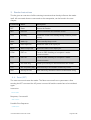
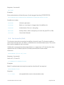
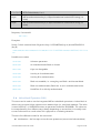
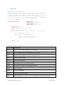
3. Reader Instructions
This list gives an overview of all the existing instructions that directly influence the reader
itself. All commands that are connected to the transponder, can be found in the next
chapter.
Command
Name
Description
RST
Reset
Resets the Reader
REV
Revision
Returns hardware and software version
STB
Standby
Sends the reader into standby/sleep mode for power
saving
WAK
Wake Up
Ends standby/sleep mode
RIP
Read Input Pin
Reads the state of an input pin
WOP
Write Output Pin
Writes the state of an output pin
CON
CRC on
Turns on CRC checking of computer / reader
communication
COF
CRC off
Turns off CRC checking of computer / reader
communication
SSK
Set Static Key
Saves up to 24 keys in the EEPROM of the reader
STK
Set Temporary Key
Save one key in the readers master key buffer
SKU
Set Key to Use
Sets which key should be used to authenticate a tag
Table 1:
Overview of reader manpulation instructions
3.1. Reset (RST)
The reset command resets the reader. The Reset command has no parameters. After
sending the RST command the HF power is turned off and the reader has to be initialized
again.
Instruction:
RST<CR>
Response, if successful:
OK!<CR>
Possible Error Response:
UPA<CR>
metraTec MiFare Protocol Guide
Page 8 of 38
3.2. Revision (REV)
The revision command requests the device type and hard- and software revision of the
reader. The reader returns its device type and it’s hard- and software revision. Revision has
no parameters and returns no error codes.
Instruction:
REV<CR>
Response, if successful:
PRODUCT_NAME<SPACE>HW_revision[4bytes]SW_revision[4bytes]<CR>
15 Bytes product name (filled with Spaces) + 4 bytes HW-Revision + 4 Bytes SoftwareRevision + <CR>
Possible Error Response:
UPA<CR>
Example for a response:
DESKID_ISO<5 Times Space>01000101<CR>
Interpretation:Product name:
DESKID_ISO
Hardware-Revision:
01.00
Software-Revision:
01.01
3.3. Standby (STB)
The standby command sets the reader in a power save mode. The RF power is turned off.
This means that all tags that might be in the field will also be powered down. If successful it
returns GN8 (“Good Night”). The reader will not accept any commands until a Wake Up
Command (WAK) is received. Standby has no parameters.
Instruction:
STB<CR>
Response, if successful:
GN8<CR>
Possible Error Response:
UPA<CR>
metraTec MiFare Protocol Guide
Page 9 of 38
3.4. Wake Up (WAK)
The wake up command ends the power save mode. Reader will restore its last state prior to
the standby. If successful it returns GMO (“Good Morning”). Wake up has no parameters.
Instruction:
WAK<CR>
Response, if successful:
GMO<CR>, DNS<CR> (if not in Standby-Mode)
Possible Error Response:
UPA<CR>
3.5. Read Input Pin (RIP)
This command is used to read the current state of an input pin. It takes one parameter,
which is the two-digit, hex-coded, zero-based number of the input pin to be read. The
possible parameter range is 00 to 01.
If successful, it returns either HI! or LOW depending on whether the input pin is high or low.
Instruction:
RIP<SPACE>Pin_No<CR>
e.g. (to read the first input pin): RIP 00<CR>
Response, if successful:
HI!<CR>
for High-State
LOW<CR>
for Low-State
Possible Error Response:
NOR<CR>, EHX<CR>, UPA<CR>
3.6. Write Output Pin (WOP)
This command is used to set the state of an output pin either to high or to low. It takes two
parameters. The first parameter is the two-digit, hex-coded, zero-based number of the
output pin to be written to. The second parameter is either “HI” or “LOW” to set the
according pin to high or low respectively. The possible parameter range is 00 to 03.
Instruction:
WOP<SPACE>Pin_No<SPACE>PIN_Setting<CR>
metraTec MiFare Protocol Guide
Page 10 of 38
e.g. Set pin 0 high: WOP<SPACE>00<SPACE>HI<CR>
e.g. Set pin 0 low:
WOP<SPACE>00<SPACE>LOW<CR>
Response, if successful:
OK!<CR>
Possible Error Response:
NOR<CR>, EHX<CR>, UPA<CR>
3.7. Cyclic Redundancy Check On (CON)
This commands turns on the Cyclic Redundancy Check (CRC) of the computer-to-reader
communication. This is used to detect transmission errors between the reader and the
computer. In general this feature is not necessary except in scenarios where you have lots of
noise on the communication bus (e.g. when using USB communication in the vicinity of
electric motors) or you encounter any other problems with communication errors.
If this feature is activated (default is off), the reader firmware expects a CRC16 (4 hex
numbers) between all commands to the reader and the respective <CR>. Between the
command and the CRC there is a space character which is included in the CRC calculation.
All answers from the reader will also be extended accordingly. The CRC used uses the 8408
polynomial, starting value is 0xFFFF. This command will work with or without the (optional)
CRC.
If successful the command returns OK! plus the according CRC of “OK! “.
Appendix 1 shows a function in C, C# & Java to calculate the correct CRC16.
Instruction:
CON<CR>
or:
CON 819E<CR>, con 2EC5<CR>
Response, if successful:
OK! 9356<CR>
Possible Error Response:
UPA<CR>
metraTec MiFare Protocol Guide
Page 11 of 38
3.8. Cyclic Redundancy Check Off (COF)
This command turns off the Cyclic Redundancy Check (CRC) of the computer-to-reader
communication. This is the default setting. This command will work with or without the
(optional) CRC.
If successful it returns OK!.
Instruction:
COF<CR>, or COF 4F5E<CR>, or cof E005<CR>
Response, if successful:
OK!<CR>
Possible Error Response:
UPA<CR>
3.9. Save Static Key (SSK)
The reader has a persistent memory which is able to save up to 24 keys for the MiFare
Crypto1 unit. The static keys in the memory of the chip are not readable and are directly
used by the Crypto1 unit of the reader. They will not be transmitted over the air interface.
Note: The sector no. is zero based
Instruction:
SSK<SPACE>[Loc]<SPACE>[Key]<CR>
Parameter
Description
Loc
Location where the key will be saved (0<=Loc<=23)
Key
6 Bytes ASCII-String (12 chars), LSB first
Table 2: Save Static Key parameter description
Response, if successful:
OK!<CR>
Examples:
Save the key 112233445566h in sector 0
SSK<SPACE>0<SPACE>112233445566<CR>
Save the key FFFFFFFFFFFFh in sector 23
metraTec MiFare Protocol Guide
Page 12 of 38
SSK<SPACE>23<SPACE>FFFFFFFFFFFF<CR>
Possible Error Response:
UPA<CR>
Unknown parameter
EDX<CR>
Location fail, or other characters than 0-9
EHX<CR>
Key-Parameter is missing or other characters than 0-9 and A-F
WDL<CR>
Key is not 6 bytes long
NOR<CR>
Location given is higher than 23
3.10. Save Temporary Key (STK)
This command saves one key in the reader temporarily until a power down or a reset occurs.
The only parameter is the Key to save, which is a 6 Byte ASCII String (12 Chars).
Instruction:
STK<SPACE>[Key]<CR>
Response, if successful:
OK!<CR>
Examples:
Save the key 112233445566h
STK<SPACE>112233445566<CR>
Possible error codes:
UPA<CR>
Unknown parameter
EHX<CR>
Key-Parameter is missing or other characters than 0-9 and A-F
WDL<CR>
Key is not 6 bytes long
3.11. Set Key to Use (SKU)
The key which will be used to authenticate a MiFare chip resp. a block of a MiFare Chip, has
to be selected with this command before using the standard authentification command
(AUT). If the direct mode from the authentication command is used, this command is not
necessary. The key can either be the temporary key or the static key.
Instruction:
metraTec MiFare Protocol Guide
Page 13 of 38
SKU<SPACE>{Type}<SPACE>[Loc]<CR>
Parameter
Description
Type
The type of the key:
Loc
TEMP
chooses the temporary key
STAT
chooses the static key
Use this parameter only with STAT-Parameter! Specifies the zero
based location of the static key. See SSK command.
Table 3: Set Key to Use parameter description
Response, if successful:
OK!<CR>
Examples:
Use the temporary key
SKU<SPACE>TEMP<CR>
Use the static key in location 2
SKU<SPACE>STAT<SPACE>2<CR>
Possible error codes:
UPA<CR>
Unknown parameter
EDX<CR>
Location fail, or other characters than 0-9 given
NOR<CR>
Location given is higher than 23
KNS<CR>
Key Not Set (if temporary key is selected, but not set before)
metraTec MiFare Protocol Guide
Page 14 of 38
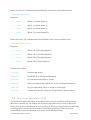
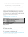
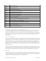
4. General ISO 14443A Commands
This list gives an overview of the existing commands that can be used with any transponder
that is based on ISO14443A, including all MiFare dialects. Any commands that are specific
to a certain type of MiFare-Type can be found in the next chapter.
Command
Name
Description
INV
Inventory
Returns all UIDs from tags in read range
SEL
Select tag
Selects a tag
RDT
Read data
Get data from tag
WDT
Write data
Write Data to a tag
Table 4: Overview of general ISO 14443A commands
4.1. Inventory (INV)
This command returns all UIDs from ISO/IEC 14443-1 to 3 compatible transponder, which
are in the read range of the reader. Only single and double UIDs are supported (all types of
ISO14443A known today). The length of the response can either be 4 bytes (single) or 7
bytes (double). Triple UIDs will be supported as soon as there are tags with this kind of UID.
Instruction:
INV<CR>
Response, if successful:
The UIDs, separated by a carriage return:
UID1<CR>
UID2<CR>
…
The end is marked by the line:
IVF<SPACE>[Count]
(Count is the number of transponders found)
Example:
INV<CR>
Response:
C22E5732<CR>
328DA79C<CR>
metraTec MiFare Protocol Guide
Page 15 of 38
IVF 02<CR>
Possible error codes:
Unknown parameter
UPA<CR>
4.2. Select Tag (SEL)
Before you can exchange data with a MiFare chip, the transponder has to be activated (or
„selected“ in the ISO14443 language). There are two different modes to select a card.
Manual Transponder Select (MTS), which needs the UID of the transponder (via a previous
INV command) or Automatic Transponder Select (ATS).
4.2.1. Manual Transponder Select (MTS )
Use this mode to select a card where the UID is known (usually by doing an INV before).
Only transponders with single or double UIDs are supported.
Instruction:
SEL<SPACE>MTS<SPACE>[UID]<CR>
Response, if successful:
[SAK]<CR>
see Appendix for the SAK codes of different chip versions
Examples:
Select a MiFare 1k Card (single UID)
SEL<SPACE>MTS<SPACE> AC410094<CR>
Select a MiFare Ultralight Card (double UID)
SEL<SPACE>MTS<SPACE> 047F77D18A0280<CR>
Possible error codes:
UPA<CR>
Unknown parameter
TNR<CR>
Tag not responding
EHX<CR>
The string cannot be interpreted as a valid UID or includes non hex
characters
4.2.2. Automatic Transponder Select (ATS )
In this mode the reader will automatically select one card in the the read range randomly.
This makes sense if you are sure that there is only one card in the field (e.g. because the
reader is integrated into a card slot).
metraTec MiFare Protocol Guide
Page 16 of 38
Sometimes it is useful to work with all cards in the field. For this purpose an optional
parameter “CYC” exists. When using the “CYC” parameter it is necessary to run an
inventory (INV) before. After that, all transponders in the inventory list will be selected
cyclically by sending SEL ATS CYC for each transponder.
Instruction:
SEL<SPACE>ATS<SPACE>CYC<CR>
Response, if successful:
[ATQA]<CR>
see Appendix for the ATQA codes of different chip versions
[SAK]<CR>
see Appendix for the SAK codes of different chip versions
[UID]<CR>
Examples:
Select a transponder currently in read range
SEL<SPACE>ATS<CR>
Select two transponders cyclically
INV<CR>
runs inventory round, e.g. with two transponders/UIDs in the field:
UID 1.: AC410094
UID 2.: C2DF6084
The select the first transponder (UID AC410094):
SEL<SPACE>ATS<SPACE>CYK<CR
Response:
0400<CR>
08<CR>
AC410094<CR>
The select the second transponder (UID C2DF6084):
SEL<SPACE>ATS<SPACE>CYK<CR
Response:
0400<CR>
08<CR>
metraTec MiFare Protocol Guide
Page 17 of 38
C2DF6084<CR>
Possible error codes:
UPA<CR>
Unknown parameter
TNR<CR>
Tag not responding (left the field since the INV command)
4.3. Read Data from Tag (RDT)
The read data command is used to retrieve the data stored in a transponder. Normally it
returns 16 bytes. For compatibility to other ISO/IEC 14443-1 to 4 transponder than MiFare
classic, it has a direct read mode, marked with the first parameter “DRT”. In this mode the
second parameter is the custom command.
Additionally, this command supports the ability to read multiple blocks with one command,
i.e. parameter “ALL” for all blocks of a sector, or “CNT” for a variable block count.
If MiFare classic is used, block has to be authenticated first (see the AUT command in the
next chapter). The command returns all blocks from a sector. If MiFare 4K is used, parameter
“All” is set and the authenticated block no. is higher than 127 it returns 16 blocks. For
Custom-Read-Commands the length of a response is maximal 64 bytes.
Instruction:
Read single Block:
RDT<SPACE>[Block No.]<CR>
Read all blocks:
RDT<SPACE>ALL<CR>
Read variable number of blocks from block No.:
RDT<SPACE>CNT<SPACE>[Block No.]< SPACE>[No. of Blocks]<CR>
Direct Read:
RDT<SPACE>DRT<SPACE>[CMD] <SPACE>[Block No.]<CR>
Parameter
Description
Block No.
No. of
Blocks
ALL
Read-Start-Block, respectively Block to read (absolute), one decimal byte
Number of blocks to read beginning at Block No., one decimal byte
Has to be bigger then 0
Read-all-parameter, marked that all blocks from sector should be read, only
MiFare 1k and 4k
CNT
Read-Count-parameter, marked that a variable number of blocks
beginning at Block No. should be read
DRT
Direct-Read-Parameter, if a Transponder needs another command than 30h
metraTec MiFare Protocol Guide
Page 18 of 38
CMD
Custom Read Command, one hexadecimal byte
Table 5: Read command parameter description
Response, if successful:
Number of lines is equal to the number of read blocks. If “DRT” is not set each line is 16
Bytes (32 ASCII chars, hexadecimal) long.
i.e. for one read block:
00112233445566778899AABBCCDDEEFF<CR>
Examples:
Read all Blocks from sector
RDT<SPACE>ALL<CR>
Read block number 11d
RDT<SPACE>11<CR>
Read 2 Blocks beginning at block 0
RDT<SPACE>CNT<SPACE>0<SPACE>2<CR>
Read 14 Blocks beginning at block 129<CR>
RDT<SPACE>CNT<SPACE>129<SPACE>14<CR>
Possible error codes:
UPA<CR>
Unknown parameter
EDX<CR>
A decimal parameter includes non decimal characters
BAE<CR>
Block no. not readable, i.e. wrong key, see Block– and Access Mode
BNA<CR>
Block no. not authenticated (only MiFare classic)
NMA<CR>
No MiFare chip 1k or 4k authenticated (only ALL-Mode)
NB0<CR>
Number of blocks to Read is 0
4.4. Write Data to Tag (WDT)
The write data command normally stores 16 bytes of data into a block (data or trailer block).
For compatibility to other ISO/IEC 14443-1 to 4 transponder than MiFare classic, the
metraTec MiFare Protocol Guide
Page 19 of 38
command also has a direct write mode, marked with the first parameter “DRT”. The number
of bytes will not be checked in this mode and it depends on the second parameter (Data).
To write to MiFare Ultralight cards (which only have four bytes per block) the first parameter
becomes “W4”. This parameter writes 4 bytes to the card.
The selected block has to be writable for this command to work.
ATTENTION
If you write wrong data to the trailer block of a sector (the fourth block of
every sector, e.g. block 3, 7, 11, etc.), the sector may become locked forever
or be even unreadable afterwards. We recommend to use the STM command
to change the information in the trailer blocks and don't write data to it
directly (although it is possible).
Instructions:
Write 16 Bytes:
WDT<SPACE>[Data]<SPACE>[Block No.]<CR>
Write 4 Bytes:
WDT<SPACE>W4<SPACE>[Data]<SPACE>[Block No.]<CR>
Write directly:
WDT<SPACE>DRT<SPACE>[CMD]<SPACE>[Data]<SPACE>[Block No.]<CR>
Parameter
Description
Data
Hexadecimal ASCII-String which represents the data. The length depends on
whether “DRT” or “W4” is set. If W4 is set the length is 8 ASCII characters (4
bytes). If nothing is set, then it is 32 ASCII characters (16 bytes).
W4
Write 4 bytes (for MiFare Ultralight)
DRT
If set: the direct mode will be used
CMD
Only with “DRT”, transponder specific write command (see datasheet)
Block No.
Absolute zero based block no. which should be written
Table 6:Write command parameter description
Response, if successful:
OK!<CR>
Examples:
Write 16 bytes to block 18d
metraTec MiFare Protocol Guide
Page 20 of 38
WDT<SPACE>00112233445566778899AABBCCDDEEFF<SPACE>18<CR>
Possible error codes:
UPA<CR>
Unknown parameter
EHX<CR>
The string cannot be interpreted as valid data or contains non hex
characters
BAE<CR>
Block no. not readable, i.e. wrong key, see Block– and Access Mode
BNA<CR>
Block no. not authenticated (only MiFare classic)
NMA<CR>
No MiFare chip 1k or 4k authenticated (only ALL-Mode)
WDL<CR>
The hex string does not have the correct length (i.e. 16 bytes in
normal mode)
metraTec MiFare Protocol Guide
Page 21 of 38
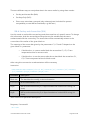
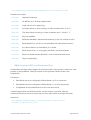
5. MiFare Classic Commands
This section describes commands only to be used with MiFare Classic (1K or 4K) chips.
Command
Name
Description
AUT
Authentication
Authenticates a sector by giving one absolute block
GAB
Get Access Bits
Return the access bits from a selected block, or sector
STM
Sector Trailer
Manipulation
Set new access bits and/or keys
VAL
Value Block
Operations
Interface to the MiFare value operations, like
initialization, increment, decrement, restore
Table 7: Overview of MiFare specific commands
5.1. Authentication (AUT)
In order to read or write data from or to MiFare classic chips, the respective memory block
has to be previously authenticated with a key. The key can either be selected by using the
SKU command (set key to use) or can be directly given as a parameter when using the direct
(DRT) parameter (direct mode).
The MiFare card has to be selected before this command works. If the Direct Mode is not
used, the SKU command has to be performed in any case.
The AUT command authenticates all the blocks in the sector you chose with Block No., i.e.
authenticating Block 5 will authenticate Blocks 4 to 7 (the entire sector 1).
NOTE
The standard password for MiFare transponders is FF FF FF FF FF FF (six
bytes).
Instruction:
AUT<SPACE>DRT<SPACE>[Key]<SPACE>{Type}<SPACE>[Block No.]<CR>
Command
Description
DRT
Parameter to mark the direct mode and the next parameter is the key
Key
The key to use, 6 Byte ASCII string (12 chars)
Type
Authenticate with key A or B (see …)
Block No.
Block which will be authenticate
Table 8: Overview of parameters of the AUT command
metraTec MiFare Protocol Guide
Page 22 of 38
Response, if successful:
OK!<CR>
Examples:
Direct authentication of block 8 (sector 2) with keytype B and key FFFFFFFFFFFFh
AUT<SPACE>DRT<SPACE>FFFFFFFFFFFF<SPACE>B<SPACE>8<CR>
Possible error codes:
UPA<CR>
Unknown parameter
BIH<CR>
Block no. is too high (i.e. bigger than 63 at MiFare 1k)
ATE<CR>
Authentication Error (i.e. wrong key)
NKS<CR>
No Key Select, select a temporary or a static key (use STK or SSK)
CNS<CR>
Card is Not Selected
5.2. Get Access Bit (GAB)
This function returns the access bits from MiFare 1K and 4K cards. The function is able to
return the access bits from one block, or all blocks from an authenticated sector. The access
bits must be readable for this command.
If Mifare 4K is used and the authenticated block no. is higher than 127, the first three lines
represent the first 15 Blocks (each line 5 blocks) and the fourth line the trailer.
Instruction:
GAB<SPACE>[Block Nr]<CR>
Response, if successful:
State of C1, C2 and C3
C1<SPACE>C2<SPACE>C3<CR>
Examples:
Block 5 is authenticated and only the access bits from block 5 are required
GAB<SPACE>5<CR>
Response:
0 0 1<CR>
(this equals block mode 4, the standard mode)
metraTec MiFare Protocol Guide
Page 23 of 38
Block 13 (sector 3) is authenticated and all blocks of this sector should be returned
GAB<SPACE>ALL<CR>
Response:
0 1 0<CR>
(Block 12 in Block Mode 2)
0 0 1<CR>
(Block 13 in Block Mode 4)
0 1 1<CR>
(Block 14 in Block Mode 5)
1 1 0<CR>
(Block 15 in Access-Mode 3)
Block 145 (sector 33) is authenticated and all blocks of this sector should be read
GAB<SPACE>ALL<CR>
Response:
0 1 0<CR>
(Block 144-148 in Block Mode 2)
0 0 1<CR>
(Block 149-153 in Block Mode 4)
0 1 1<CR>
(Block 154-159 in Block Mode 5)
1 1 0<CR>
(Block 160 in Access-Mode 3)
Possible error codes:
UPA<CR>
Unknown parameter
NMA<CR>
No MiFare 1k or 4k chip authenticated
BAE<CR>
An unauthenticated block is chosen
BNA<CR>
Block not authenticated, Block No. is not in authenticated sector
TNR<CR>
Tag not responding (Tag is no longer in read range)
EDX<CR>
A decimal parameter cannot be interpreted as a decimal value
5.3. Sector Trailer Manipulation (STM)
This function simplifies the usage of the MiFare classic access conditions and key writing.
With this command you can change the access bits and don't have to write to the trailer
blocks directly which should reduce errors resulting in destroyed transponders. As described
in the Appendix, the sector trailer contains information about keys, block-mode and
Access-Modes. Use this command to set these access bits and/or keys.
metraTec MiFare Protocol Guide
Page 24 of 38
There are different ways to manipulate data in the sector trailer by using these modes:
Set key and Access Bits (SKA)
Set Keys Only (SKO)
Direct over write-data command (only advanced user! Included for upward
compatibility to new MiFare Standards, e.g. MiFare+)
5.3.1. Set key and Access bits (SKA)
Use this mode to set both the access keys and the access bits of a specific sector. To change
this information, both the access bits and keys have to be writable and the sector
authenticated with the correct key. The access bits will be automatically written to the
correct bits of the trailer of the given block no.
The meaning of the access bits given by the parameters C1, C2 and C3 depend on the
given block no. parameter.:
o
If the block no. is a sector trailer block the access bits C1, C2, C3 are
interpreted as bits for access mode.
o
If the block no. is not the sector trailer but a data block the access bits C1,
C2, C3 are interpreted as bits for block mode.
After using this command a re-authentication will be necessary
Instruction:
STM<SPACE>SKA<SPACE>[Block No]<SPACE>[C1]<SPACE>[C2]<SPACE>
[C3]<SPACE>[KeyA]<SPACE>[KeyB]<CR>
Parameter
Description
Block No.
The data block to modify, in decimal notation
C1, C2, C3
BCD-Coded Mode, 0 or 1
KeyA
MiFare authentication key A; 6 Bytes hexadecimal coded ASCII-string (16
chars)
KeyB
MiFare authentication key B; 6 Bytes hexadecimal coded ASCII-string (16
chars)
Table 9: SKA mode parameter description
Response, if successful:
OK!<CR>
metraTec MiFare Protocol Guide
Page 25 of 38
Examples:
Write Key A (665544332211), Key B (112233445566) and block mode 3 (1 1 0) for block 2
STM<SPACE>SKA<SPACE>2<SPACE>1<SPACE>1<SPACE>0<SPACE>6655443322
<SPACE>
112233445566<CR>
Write Key A (000000000000), Key B (FFFFFFFFFFFF) and access mode 3 (1 0 1) for block 3
STM<SPACE>SKA<SPACE>2<SPACE>1<SPACE>0<SPACE>1<SPACE>0000000000
00<SPACE>
FFFFFFFFFFFF <CR>
Possible error codes:
UPA<CR>
Unknown parameter
BAE<CR>
An unauthenticated block is chosen
BNA<CR>
Block not authenticated, Block No. is not in authenticated sector
BNC<CR>
Parameter C1, C2 or C3 missing
AKW<CR>
Access bits or Keys not Writable
UKB<CR>
Use Key B for authentication (in Access-Mode 5 and 6)
UKA<CR>
Use Key B for authentication (in Access-Mode 0 and 4)
TNR<CR>
Tag not responding (Tag is no longer in read range)
NMA<CR>
No MiFare 1k or 4k chip authenticated
5.3.2. Set Key Only (SKO)
Use this command to change only the key of a specific sector. The sector trailer has to be in
Access-Mode 6, 1 (authenticated with key B) or 4, 0 (authenticated with key A) for this
command to work.
Instruction:
STM<SPACE>SKO<SPACE>[Block No.]<SPACE>[KeyA]<SPACE>[KeyB]<CR>
Parameter
Description
Block No.
The data block to modify, in decimal notation
metraTec MiFare Protocol Guide
Page 26 of 38
C1, C2, C3
BCD-Coded Mode, 0 or 1
KeyA
MiFare authentication key A; 6 Bytes hexadecimal coded ASCII-string (16
chars)
KeyB
MiFare authentication key B; 6 Bytes hexadecimal coded ASCII-string (16
chars)
Table 10: SKO mode parameter description
Response, if successful:
OK!<CR>
Examples:
Sector 5 which contains block 20 get the keys 112233445566 (key A) and 665544332211
(key B)
STM<SPACE>SKO<SPACE>20<SPACE>112233445566<SPACE>665544332211<C
R>
Possible error codes:
UPA<CR>
Unknown parameter
BAE<CR>
An unauthenticated block is chosen
KNC<CR>
Keys not changeable
UKA<CR>
Use Key A for authentication
UKB<CR>
Use Key B for authentication
BNR<CR>
Block not readable, i.e. wrong key, see Block –and Access Mode
BNA<CR>
Block not authenticated, Block No. is not in authenticated sector
NMA<CR>
No MiFare 1k or 4k chip authenticated
5.4. Value block Operation (VAL)
This command is used to use the integrated MiFare valueblock operations. A value block is
able to save a signed 4 byte value and one address byte (i.e. own block address). The value
is saved LSB first, i.e. 00000035h written as parameter looks like 35000000h. The value can
be manipulated by four different ways (always depending on access bits). It is usually used
to store information on credit values for e-payment or e-ticketing situations.
There are five different modes for this command:
Initialization – the first step to use the next operations (sets a initial value/address)
metraTec MiFare Protocol Guide
Page 27 of 38
Increment - adds a value (given as parameter) to the value present in a chosen block
(inputblock) and writes the result to the outputblock. (Mode 3)
Decrement - subtracts a value (given as parameter) to the value present in a chosen
block (inputblock) and writes the result to the outputblock. (Mode 3, 4)
Direct Write - writes 4 value bytes and one address byte direct to the Block (Mode 3)
Restore - Writes the Date from the outputblock to the inputblock. (Mode 3, 4)
5.4.1. Initialization of a value block (INIT)
In order to use the Increment, Decrement and Restore function, the data block has to be
configured as a value block (Block Mode 3) or in transport configuration (Block Mode 0).
This function initializes the MiFare data block to the correct format. In this way an initial
value and an initial address has to be given (see Backup Configuration in chapter … for
details of the address). If the initialization is done, the block mode can changed to 4 via the
STM command. The block has to be writeable, in block mode 0 or 3. When authenticated
with key B and key B is readable, the block is not read/writable.
Instruction:
VAL<SPACE>INIT<SPACE>[Value]<SPACE>[Block
No.]<SPACE>[Address]<CR>
Parameter
Description
Value
Signed and always positive 4 byte, hexadecimal Value
Block No.
The data block to modify, in decimal,
i.e. for MiFare 1k 0..63, for MiFare 4k 0..255
Address
Initial address, one decimal byte
Table 11: Init mode parameter description
Response, if successful:
OK!<CR>
Examples:
The Block Mode is set to mode 3 by another way. The initial value should be 2000h. The
block to configure is block number. 4.
VAL<SPACE>INIT<SPACE>00002000<SPACE>04<CR>
The Access bits are changeable and the block number 5 should become a value block with
write and increment rights. The initial value should be 2020h.
VAL<SPACE>INIT<SPACE>SAB<SPACE>WI<SPACE>00002020<SPACE>05<CR>
Now the block becomes Mode 4. The value is only a dummy.
metraTec MiFare Protocol Guide
Page 28 of 38
VAL<SPACE>INIT<SPACE>SAB<SPACE>00202000<SPACE>05<CR>
Possible error codes:
UPA<CR>
Unknown Parameter
NMA<CR>
No MiFare 1k or 4k chip authenticated
WDL<CR>
Initial value is not 6 bytes long
EDX<CR>
In/Output block or value missing, or other character than ‘0’ to ‘9’
EHX<CR>
The initial value is missing, or other characters the 0.. 9 and A .. F
KBR<CR>
Key B is readable
BNW<CR>
Block-Not-Writable: authenticated with key A, but not in block mode 0
BME<CR>
Block Mode Error, not 0 or 3 (not writeable with value block function)
NDB<CR>
the chosen Block is no Data Block, it’s a trailer
BAE<CR>
Block access error, i.e. wrong key, see Block –and Access Mode
BNA<CR>
Block not authenticated, Block No. is not in authenticated sector
TNR<CR>
Tag not responding
5.4.2. Increment (INC) and Decrement (Dec)
As described at begin of this chapter, this function adds or decrements a value to a value
present in the inputblock. Finally the result of this operation will be saved in the
outputblock.
Conditions:
Data block has to be configured to Block Mode 0 or 3 for increment
Data block has to be configured to Block Mode 0, 3 or 4 for decrement
Outputblock and inputblock have to be in the same sector
If input/output blocks are different blocks, use the restore command, else the
increment/decrement function works only one time (the results are always the same)
Instruction:
VAL<SPACE>{MODE}<SPACE>[Value]<SPACE>[Inputblock]
<SPACE>[Outputblock]<CR>
metraTec MiFare Protocol Guide
Page 29 of 38
Parameter
Description
MOD
Selected either increment (INC) or decrement (DEC)
VALUE
unsigned hexadecimal value (summand/subtrahend)
Inputblock
1 decimal Byte, i.e. 0 to 63 for Mifare 1k, or 0 to 255 for Mifare 4k, but not
trailer
Outputblo
ck
1 decimal Byte, i.e. 0 to 63 for Mifare 1k, or 0 to 255 for Mifare 4k, but not
trailer
Table 12: INC and DEC mode parameter description
Response, if successful:
[VALUE]<CR>
4 bytes long result of the operation
Examples:
Increment the value from block 32d by 10d and write the result to block 32d
VAL<SPACE>INC<SPACE>10<SPACE>32<SPACE>32<CR>
Decrement the value from block 32d by 10d and write the result to block 32d
VAL<SPACE>DEC<SPACE>10<SPACE>32<SPACE>32<CR>
Increment the value from block 32d by 20d and write the result to block 33d
VAL<SPACE>INC<SPACE>20<SPACE>32<SPACE>33<CR>
Possible error codes:
UPA<CR>
Unknown Parameter
TNR<CR>
Tag no response, i.e. value block not incrementable
EDX<CR>
In/Output block or value missing, or other character than ‘0’ to ‘9’
NDB<CR>
The chosen block is no data block but a trailer
NMA<CR>
No MiFare 1k or 4k chip authenticated
ONE<CR>
Operation not Executed, Result smaller/bigger than ±2,147,483,647
VNI<CR>
The Value block is not in the right format, use INIT comman
metraTec MiFare Protocol Guide
Page 30 of 38
5.4.3. Restore
This command is used for powerful backups. If the input –and outputblock are not the same,
this command restores the result written in the outputblock to the inputblock. The
outputblock has to be in the correct value block format for this command to work.
Instruction:
VAL<SPACE>REST<SPACE>[ Outputblock] <SPACE>[ Inputblock]<CR>
Response, if successful:
OK!<CR>
Examples:
The result of an operation is saved in block 29d and should restore to 28d
VAL<SPACE>REST<SPACE>29<SPACE>28
Possible error codes:
UPA<CR>
Unknown Parameter
TNR<CR>
Tag no response, i.e. value block not incrementable
EDX<CR>
In/Output block or value missing, or other character than ‘0’ to ‘9’
NDB<CR>
The chosen block is no data block but a trailer
NMA<CR>
No MiFare 1k or 4k chip authenticated
BNA<CR>
In- or Outputblock is not authenticated
VNI<CR>
The Value block is not in the right format, use INIT command first
metraTec MiFare Protocol Guide
Page 31 of 38
6. Appendix
Appendix 1: CRC Calculation
//
//
//
//
//
//
//
this function calculates a CRC16 over a unsigned char Array with, LSB first
@Param1 (DataBuf): An Array, which contains the Data for Calculation
@Param2 (SizeOfDataBuf): length of the Data Buffer (DataBuf)
@Param3 (Polynom): Value of the Generatorpolynom, 0x8408 is recommended
@Param4 (Initial_Value): load value for CRC16, 0xFFFF is recommended for
host to reader communication
return: calculated CRC16
unsigned short GetCrc(
unsigned
unsigned
unsigned
unsigned
char *DataBuf,
char SizeOfDataBuf,
short Polynom,
short Initial_Value)
{
unsigned short Crc16;
unsigned char Byte_Counter, Bit_Counter;
Crc16 = Initial_Value;
for (Byte_Counter=0; Byte_Counter < SizeOfDataBuf; Byte_Counter++)
{
Crc16^=DataBuf[Byte_Counter];
for (Bit_Counter=0; Bit_Counter<8; j++)
{
if (( Crc16 & 0x0001)==0) Crc16>>=1;
else Crc16=(Crc16>>1)^Polynom;
}
}
return (Crc16);
}
Appendix 2: Error Codes:
Error Code
Description
EDX
Error Decimal value Expected, or is missing
EHX
Error Hexadecimal value Expected, or is missing
IOS
Input and Outputblock are not in the same Sector
TNR
Tag Not Responding
UPA
Unknown Parameter
NMA
No MiFare classic chip Authenticated
WDL
Wrong Data Length of hex-string-parameter
NDB
No Data Block
KBR
Key B is Readable
ONE
Operation Not Executed
BME
Block Mode Error, not 0 or 3 (not writeable with value block function)
metraTec MiFare Protocol Guide
Page 32 of 38
BNW
Block Not Writable
BAE
Block Access Error
BNA
Block Not Authenticated
AKW
Access bits or Keys not Writable
UKB
Use Key B for authentication
UKA
Use Key B for authentication
KNC
Keys not changeable
BIH
Block is too high (i.e. bigger than 63 at MiFare 1k)
ATE
Authentication Error (i.e. wrong key)
NKS
No Key Select, select a temporary or a static key
CNS
Card is Not Selected
NB0
Number of Blocks to Read is 0
Table 13: Overview of error codes
Appendix 3: General Information on MiFare Systems
Since MiFare transponders have serveral specialties esp. with regard to the access system
used, this paragraph is meant to give a quick overview about these topics. For an even
deeper understanding of the matter, please refer to the respective datasheets of the MiFare
transponders you are using. You can get these directly from NXP after signing an NDA via
their website.
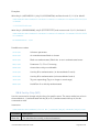
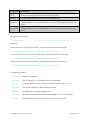
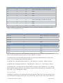
Memory Organisation
The memory of MiFare classic chips is organized in sectors composed of several numbers of
data blocks and one trailer. MiFare 1K chips contain 16 sectors of 3 data blocks and one (the
fourth) trailer (Table 14). For the lower 32 sector of MiFare 4K chips the same applies. The
higher 8 sectors are composed of 15 data blocks and one (the 16th) trailer block(Table 15).
All blocks are read-/writable only if the corresponding sector was successfully authenticated.
The Trailer Block:
The trailer contains two secret keys (A and B) to authenticate the corresponding sector and
information about access rights (the access bits). Teh trailer block is always the last block in a
sector. This means that each sector can have its own keys for giving write or read access.
Data blocks:
The data blocks contain 16 read-/writable bytes depending on the access bits in the sector
trailer, except block 0 in sector 0, which is a read-only manufacturer block. These blocks can
configured as normal read/write blocks or as value blocks.
metraTec MiFare Protocol Guide
Page 33 of 38
Sector
Block
Absolute Block Nr
Funktion
15
3
63
Sector Trailer (Key A, access bits, Key B)
15
2
62
Data
15
1
61
Data
15
0
60
Data
…
…
…
…
0
3
3
Sector Trailer (Key A, access bits, Key B)
0
2
2
Data
0
1
1
Data
0
0
0
Data
Table 14: Memory organization of the MiFare 1k chip (16 sectors á 4 blocks á 16 bytes (Sector 0 in
Block 0 is the manufacturer block)
Sector
Block
Funktion
32 to 39
15
Sector Trailer (Key A, Access, Key B)
32 to 39
14
Data
32 to 39
…
…
32 to 39
0
Data
0 to 31
3
Sector Trailer (Key A, Access, Key B)
0 to 31
2
Data
0 to 31
1
Data
0 to 31
0
Data
Lower blocks
Table 15: Memory organization of the MiFare 4k chip (Sector 0 to 31: 4 blocks á 16 bytes (Sector 0 in
Block 0 is the manufacture block); Sector 31 to 39: 16 blocks á 16 bytes)
At authentication and all read/write processes the zero base absolute block number must
given. This is calculated with following equation:
for MiFare 1k or 4k and absolute block Nr < 128: Block Nr = Sector*4 + Block in Sector
for MiFare 4k and absolute block Nr > 128: Block Nr = Sector*16 + 128 + Block in Sector
where Block No. is the absolute zero based block number (0..63 for MiFare 1k, or 0..255 for
MiFare 4k) and Block in Sector is the position of the block in the sector (0..3 for MiFare 1k &
4k (<128) , or 0..15 MiFare 4k (>128))
Access Rights
All MiFare Cards have a fine grained access rights system. Each sector can be secured using
two different keys (Key A and Key B). Using access bits, you can give read or write access to
metraTec MiFare Protocol Guide
Page 34 of 38
one or both of the keys for each block. That means, that e.g. you can use Key A in your
customer application which is only able to read the data, but use Key B in your internal
application to initialize the cards with full write access.
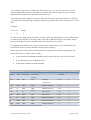
To identify the access rights for a sector there are three bits, called access bits C1, C2 and
C3. With these three bits eight different modes are possible with these access bits. C1 is the
LSB.
Example:
C1 C2 C3
1
1
Mode
0
3
There are four access rights per sector (one for each three data blocks and one trailer block),
so each block at MiFare 1k and the lower 32 blocks at MiFare 4k has its own three access
bits. At the higher 8 sectors of MiFare 4k five blocks shares one mode.
So depending on wether you set the access bits of a data block or of a trailer block (the
fourth block of each sector) these bits change their meaning.
When writing the access bits of a data block you can define the following things for this
block (this setting is called „block mode“).
Is the data block readable/writeable and by which key (Key A or Key B or both)
Is it a value block or a read/write block
Is the block locked (not read/writable)
Access Conditions
Read
Write
Increment
Application
Decrement,
Access bits
Block Mode
C1 C2 C3
Restore
A|B
A|B1
A|B1
A|B1
transport
000
0
configuration
A|B
NEV
NEV
NEV
Read/write Block
010
2
A|B
B1
NEV
NEV
Read/write Block
100
1
A|B
B1
B1
A|B1
Value Block
110
3
A|B
NEV
NEV
A|B1
Value Block
001
4
B
B1
NEV
NEV
Read/write Block
011
6
B
NEV
NEV
NEV
Read/write Block
101
5
NEV
NEV
NEV
NEV
Read/write Block
111
7
Table 16: Access Bit meaning in „Block-mode“
metraTec MiFare Protocol Guide
Page 35 of 38
Block Mode 0: This is the transport configuration (delivery state). In this mode the block is
readable and all data manipulating commands are enabled.
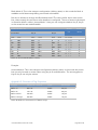
But who is allowed to change the Block Mode itself? The sector trailer has its own access
bits, where exactly this and some other details are configured. The set of access right stored
in the trailer block is called „Access Mode“. Here you can configure whether Key A, Key B
or the access bits are read/writeable.
Access condition for
Access
Access-
bits
Mode
Access Bits
Key A
Key B
read
write
read
write
read
write
C1 C2 C3
A
NEV
NEV
A
A
A
0
0 0
0
A|B
NEV
NEV
B
NEV
B
1
0 0
1
A
A|B
A
A|B
NEV
NEV
A
B
NEV
NEV
NEV
NEV
NEV
NEV
A
NEV
A
NEV
A
NEV
NEV
NEV
A
NEV
0
1
0
1
1
1
0
0
0
0
1
1
2
3
4
5
A|B
B
NEV
B
A|B
NEV
NEV
NEV
Table 17: Access-Modes (NEV = Never)
NEV
NEV
B
NEV
0
1
1 1
1 1
6
7
Example:
Access-Mode 4: This is the transport configuration (delivery state). In this mode the access
bits can only be read or written when using key A for authentication. The same applies to
Key B. Key A can only be written.
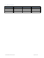
Appendix 5: Overview of Tag Properties
Tag-type
SAK (Level 1/Level 2)
ATQA
UID Length
Mifare 1k
08h/ XX
0400h
4 Bytes
Mifare 4k
18h/ XX
0200h
4 Bytes
Mifare Desfire
24h/20h
4403h
7 Bytes
Mifare Ultralight
04h/00h
4400h
7 Bytes
Table 18: Different characteristics of MiFare Chips
metraTec MiFare Protocol Guide
Page 36 of 38
7. Version Control
Version
Change
by
Date
1.0
created
KD
11.3.2009
metraTec MiFare Protocol Guide
Page 37 of 38
Contact / Support
metraTec GmbH
Werner-Heisenberg-Str. 1
D-39106 Magdeburg
Tel.: +49 (0)391 251906-00
Fax: +49 (0)391 251906-01
Email: [email protected]
Web: http://www.metratec.com
Copyright
© 2009 metraTec GmbH
Nachdruck, Vervielfältigung oder Übersetzung dieser Benutzeranleitung, auch auszugsweise, sind
ohne schriftliche Genehmigung der metraTec GmbH nicht gestattet.
Alle Marken sind Eigentum ihrer jeweiligen Inhaber.
Alle Rechte vorbehalten.
Wir arbeiten ständig an der Weiterentwicklung unserer Produkte. Änderungen in Form, Ausstattung
und Funktionalität unserer Produkte behalten wir uns ausdrücklich vor.
metraTec MiFare Protocol Guide
Page 38 of 38