1
HARDWARE MANUAL
F940GOT Handy Series (F94*GOT-*BD-RH-E)
Foreword
• This manual contains text, diagrams and explanations which will guide the reader in the
correct installation and operation of the F940GOT Handy Series. It should be read and
understood before attempting to install or use the unit.
• Further information can be found in the GOT-F900 Series Operation Manual, GOT-900
Series Hardware Manual and manual of the associated PLC.
• If in doubt at any stage of the installation of F940GOT Handy Series always consult a
professional electrical engineer who is qualified and trained to the local and national
standards which apply to the installation site.
• If in doubt about the operation or use of F940GOT Handy Series please consult the nearest
Mitsubishi Electric distributor.
• This manual is subject to change without notice.
F940GOT Handy Series
F940GOT Handy Series
(F94*GOT-*BD-RH-E)
Hardware Manual
Manual number : JY992D99901
Manual revision : C
Date
: September 2008
i
F940GOT Handy Series
ii
F940GOT Handy Series
FAX BACK
Mitsubishi has a world wide reputation for its efforts in continually developing and pushing back
the frontiers of industrial automation. What is sometimes overlooked by the user is the care
and attention to detail that is taken with the documentation. However, to continue this process
of improvement, the comments of the Mitsubishi users are always welcomed. This page has
been designed for you, the reader, to fill in your comments and fax them back to us. We look
forward to hearing from you.
Fax numbers:
Your name: ...................................................
Mitsubishi Electric....
.....................................................................
America
(01) 847-478-2253
Your company: .............................................
Australia
(02) 638-7072
.....................................................................
Germany
(0 21 02) 4 86-1 12
Your location:................................................
Spain
(34) 93-589-1579
.....................................................................
United Kingdom
(01707) 278-695
Please tick the box of your choice
What condition did the manual arrive in?
Good
Minor damage
Will you be using a folder to store the manual?
Yes
No
What do you think to the manual presentation?
Tidy
Unfriendly
Are the explanations understandable?
Yes
Not too bad
Unusable
Unusable
Which explanation was most difficult to understand: ..................................................................
....................................................................................................................................................
Are there any diagrams which are not clear?
Yes
No
If so,which: ..................................................................................................................................
What do you think to the manual layout?
Good
Not too bad
Unhelpful
If there one thing you would like to see improved, what is it? .....................................................
....................................................................................................................................................
....................................................................................................................................................
Could you find the information you required easily using the index and/or the contents, if
possible please identify your experience: ...................................................................................
....................................................................................................................................................
....................................................................................................................................................
....................................................................................................................................................
....................................................................................................................................................
Do you have any comments in general about the Mitsubishi manuals? .....................................
....................................................................................................................................................
....................................................................................................................................................
....................................................................................................................................................
....................................................................................................................................................
Thank you for taking the time to fill out this questionnaire. We hope you found both the product
and this manual easy to use.
iii
F940GOT Handy Series
iv
F940GOT Handy Series
Guidelines for the Safety of the User and Protection of the F940GOT Handy
Series (F94*GOT-*BD-RH-E)
This manual provides information for the use of the F940GOT Handy Series. The manual has
been written to be used by trained and competent personnel. The definition of such a person
or persons is as follows;
a) Any engineer who is responsible for the planning, design and construction of automatic
equipment using the product associated with this manual should be of a competent
nature, trained and qualified to the local and national standards required to fulfill that
role. These engineers should be fully aware of all aspects of safety with regards to
automated equipment.
b) Any commissioning or service engineer must be of a competent nature, trained and
qualified to the local and national standards required to fulfill that job. These engineers
should also be trained in the use and maintenance of the completed product. This
includes being completely familiar with all associated documentation for the said product.
All maintenance should be carried out in accordance with established safety practices.
c) All operators of the completed equipment (see Note) should be trained to use this
product in a safe manner in compliance to established safety practices. The operators
should also be familiar with documentation which is associated with the operation of the
completed equipment.
Note : The term ‘completed equipment’ refers to a third party constructed device which
contains or uses the product associated with this manual.
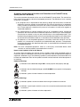
Notes on the Symbols Used in this Manual
At various times throughout this manual certain symbols will be used to highlight points of
information which are intended to ensure the users personal safety and protect the integrity of
equipment. Whenever any of the following symbols are encountered its associated note must
be read and understood. Each of the symbols used will now be listed with a brief description of
its meaning.
Hardware Warnings
1) Indicates that the identified danger WILL cause physical and property damage.
2) Indicates that the identified danger could POSSIBLY cause physical and property
damage.
3) Indicates a point of further interest or further explanation.
Software Warnings
4) Indicates special care must be taken when using this element of software.
5) Indicates a special point which the user of the associate software element should
be aware of.
6) Indicates a point of interest or further explanation.
v
F940GOT Handy Series
• Under no circumstances will Mitsubishi Electric be liable or responsible for any
consequential damage that may arise as a result of the installation or use of this equipment.
• All examples and diagrams shown in this manual are intended only as an aid to
understanding the text, not to guarantee operation. Mitsubishi Electric will accept no
responsibility for actual use of the product based on these illustrative examples.
• Please contact a Mitsubishi Electric distributor for more information concerning applications
in life critical situations or high reliability.
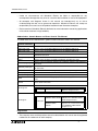
Abbreviations, Generic Names and Terms Used in This Manual
The table below shows abbreviations, generic names and terms used in this manual.
Abbreviation/
generic name/term
Description
Handy GOT
Generic name of F94GOT-SBD-RH-E and F94GOT-LBD-RH-E (=0 or 3)
F940 Handy GOT
Generic name of F940GOT-SBD-RH-E and F940GOT-LBD-RH-E
F943 Handy GOT
Generic name of F943GOT-SBD-RH-E and F943GOT-LBD-RH-E
QCPU (Q mode)
Generic name of Q02CPU, Q02HCPU, Q06HCPU, Q12HCPU and
Q25HCPU CPU units
QCPU (A mode)
Generic name of Q02CPU-A, Q02HCPU-A and Q06HCPU-A CPU units
QCPU
Generic name of QCPU (Q mode) and QCPU (A mode) CPU units
QnACPU (large type)
Generic name of Q2ACPU, Q2ACPU-S1, Q3ACPU, Q4ACPU and Q4ARCPU
CPU units
QnACPU (small type)
Generic name of Q2ASCPU, Q2ASCPU-S1, Q2ASHCPU and Q2ASHCPUS1 CPU units
QnACPU
Generic name of QnACPU (large type) and QnACPU (small type) CPU units
ACPU (large type)
Generic name of AnUCPU, AnACPU and AnNCPU CPU units
ACPU (small type)
Generic name of A2US(H)CPU, AnS(H)CPU and A1SJ(H)CPU CPU units
ACPU
Generic name of ACPU (large type), ACPU (small type) and A1FXCPU CPU
units
FXCPU
Generic name of FX0, FX0S, FX1S, FX0N, FX1N, FX1, FX2, FX2N, FX2C and
FX2NC Series CPU units
Abbreviation of screen creation software for GOT-A900/GOT-F900 Series
GT Designer2
GT Designer2 SWD5C-GTD2-E
Screen creation software for GOT900 Series (English version)
Abbreviation of screen creation software for GOT-A900/GOT-F900 Series
GT Designer
Screen creation software for
SWD5C-GOTR-PACKE GOT900 Series SWD5C-GOTRPACKE (English version)
GT Designer
SWD5C-GOTRPACKEV
Software dedicated to version
upgrade from conventional version to
latest SWD5C-GOTR-PACKE
(English version)
Registration
• The company name and the product name to be described in this manual are the registered
trademarks or trademarks of each company.
vi
Contents
F940GOT Handy Series
Table of Contents
Guideline for Safety ............................................................................. iii
Associated Manual Lists............................................................................. vii
1. Introduction............................................................................................1-1
1.1 Introduction .......................................................................................................... 1-1
1.1.1 Product Components................................................................................................. 1-2
1.2 Product Lists ........................................................................................................ 1-3
1.2.1 Model Name .............................................................................................................. 1-3
1.2.2 Handy GOT Main Unit ............................................................................................... 1-3
1.3 Options ................................................................................................................ 1-4
1.3.1 External Cable ........................................................................................................... 1-4
1.3.2 Other Options ............................................................................................................ 1-4
1.3.3 Spare Parts ............................................................................................................... 1-5
1.4 Dimensions and Part Names ............................................................................... 1-6
1.4.1 Dimensions and Part Names of Front Panel ............................................................. 1-6
1.4.2 Rear Panel ................................................................................................................ 1-7
2. Specifications ........................................................................................2-1
2.1
2.2
2.3
2.4
2.5
Outside dimensions ............................................................................................. 2-2
Power Supply Specifications ............................................................................... 2-3
General Specifications......................................................................................... 2-3
Screen Hardware Specifications ......................................................................... 2-4
Switch Specifications ........................................................................................... 2-4
3. Installation .............................................................................................3-1
3.1 Installation Method .............................................................................................. 3-1
3.1.1
3.1.2
3.1.3
3.1.4
Holding ...................................................................................................................... 3-1
Wall Mounting............................................................................................................ 3-2
Flat Surface Mounting ............................................................................................... 3-2
Hand/Shoulder Strap ................................................................................................. 3-3
3.2 Outline of Connection .......................................................................................... 3-4
3.2.1 Signal Allocation of Connector .................................................................................. 3-4
3.3 Installation of External Cable ............................................................................... 3-6
3.3.1 Caution for CE EMC .................................................................................................. 3-8
3.4 Processing Panel for a Control Box or Cabinet ................................................... 3-9
3.4.1
3.4.2
3.4.3
3.4.4
Using the F940GOT Handy ....................................................................................... 3-9
Using the F943GOT Handy ..................................................................................... 3-10
Pinouts for the Relay Cable..................................................................................... 3-11
Panel Cut Dimensions for the Relay Cable ............................................................. 3-12
4. Preparation of the Operation Switch Name Sheet ................................4-1
4.1 Preparing the Name Sheet .................................................................................. 4-1
4.2 Attaching the Sheet ............................................................................................. 4-2
vii
Contents
F940GOT Handy Series
5. Maintenance and Diagnostics ...............................................................5-1
5.1 Maintenance ........................................................................................................ 5-1
5.1.1 Replacement of the Battery ....................................................................................... 5-1
5.2 Diagnostics .......................................................................................................... 5-2
5.2.1 Preliminary Check ..................................................................................................... 5-2
5.2.2 When an operation switch or emergency stop switch does not operate ................... 5-3
5.2.3 When the LCD screen is dark ................................................................................... 5-4
5.3 Check Error Messages ........................................................................................ 5-4
viii
Associated Manual Lists
F940GOT Handy Series
Associated Manual Lists
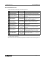
Further information can be found in the following manuals.
Manual Title
Manual Number
Description
|
F940 Handy Series
HARDWARE MANUAL
(F94*GOT-*BD-RH-E)
~
GOT-F900
OPERATION MANUAL
(describes GT Designer2)
Describes the operation and use of the GOTJY992D09101
F900 Series graphic operation terminals and GT
(separate volume)
Designer2.
~
GOT-F900 Series
Operation Manual
Describes the operation and use of the GOTJY992D94701
F900 Series graphic operation terminals, GT
(separate volume)
Designer and FX-PCS-DU/WIN-E.
~
GOT-F900 Series
Hardware Manual
(connection diagram)
JY992D94801
Describes wiring and installation of the GOT(separate volume) F900 Series graphic operation terminals.
|
GT Designer2 Version1
Operating Manual
(PDF files on CD- Describes the operation of GT Designer2
ROM included with (SW*D5C-GTD2-E) and data transfer to the
GOT-900 Series.
product)
|
GT Designer2 Version1
Reference Manual
(PDF files on CD- Describes the specifications and setting of
ROM included with object functions in GT Designer2 (SW*D5CGTD2-E).
product)
|
GT Designer
Operating Manual
Included with the
screen creation
software
|
FX-PCS-DU/WIN-E
SOFTWARE MANUAL
JY992D68301
(included with the Describes the operation of FX-PCS-DU/WIN-E
screen creation screen creation software.
software)
JY992D99901
Describes the specifications, installation,
setting, and operation switches of the F940
Handy graphic operation terminal (RH model).
Describes the operation of GT Designer
(SW*D5C-GOTR-PACKE) and data transfer to
the GOT-900 Series. (Refer to the help file)
~: Indispensable manual
{: Either manual is necessary.
Refer to the manual of the connected programmable controller for details concerning that unit.
ix
F940GOT Handy Series
Associated Manual Lists
MEMO
x
F940GOT Handy Series
1.
Introduction
1.1
Introduction
Introduction 1
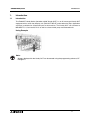
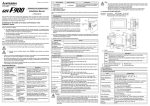
The F940GOT Handy Series (hereafter called "Handy GOT") is an all-in-one type Handy GOT
equipped with a touch key display unit (F94*GOT-*WD-E) and mechanical keys (operation
switches) available for command input to the machine. The Handy GOT can connect to
MELSEC FX, A, QnA and Q PLCs as well as a host of third party manufactured units.
Using Example
Note:
Screens displayed for the Handy GOT can be created using the programming software, GT
Designer 2.
1-1
F940GOT Handy Series
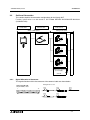
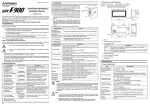
1.1.1
Introduction 1
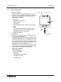
Product Components
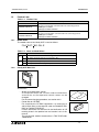
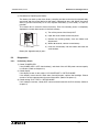
1) Operation switches
These switches can be connected to the inputs on
the PLC, when immediate response from the
machine such as operation and stop is required.
Application Examples:
• Start/stop
• Preparation for operation
• Setup change
• Error reset
• Mode selection between automatic and manual
K e y lo c k s w itc h
E m e r g e n c y s to p s w itc h
D is p la y
u n it
P O W E R
G R IP S W
Note:
The name of these operation switches can be
personalized using a transparent sheet and a
label sheet offered as accessories.
(Refer to Chapter 4)
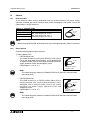
2) Display unit
The display unit is touch-key type LCD equivalent to
that of a standard F940GOT.
All functions offered in the standard F940GOT are
available in the Handy GOT. The operator can easily
monitor the ON/OFF status of bit devices in the
PLC, set bit devices to ON/OFF, monitor the set
value and the current value of word devices, and
change such values of word devices.
This display unit can be used to change the setup,
or set values, and perform troubleshooting, as well
as give system information to the operator.
Application Examples:
• Manual operation
• One-cycle operation
• Monitoring
• Forcing devices ON and OFF
• Change of set values
• Troubleshooting
O p e r a tio n
s w itc h e s
E x te r n a l c a b le
( o p tio n )
1-2
Introduction 1
F940GOT Handy Series
1.2
Product Lists
Table 1.1: Product Lists
Production Name
F940GOT-SBD-RH-E
Handy GOT main unit
This type uses RS-422 communication for connecting to PLC.
- SBD type is 8 Colors
- LBD type is White and black
F940GOT-LBD-RH-E
F943GOT-SBD-RH-E
Handy GOT main unit
This type uses RS-232C communication for connecting to PLC.
- SBD type is 8 Colors
- LBD type is White and black
F943GOT-LBD-RH-E
1.2.1
Description
Model Name
The model name of the Handy GOT is read as follows.
F 9 4* G OT-* B D -R H -E
A
B
Table 1.2: Notes on Model Name
Description
A
B
1.2.2
0
RS-422 communication for connecting to PLC
3
RS-232C communication for connecting to PLC
S
STN type 8 colors liquid crystal
L
STN type black and white liquid crystal
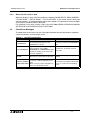
Handy GOT Main Unit
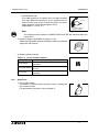
PO
WER
GR
IP
SW
Accessories:
- Sheets to change switch names
A transparent sheet and a mount sheet are offered as
accessories so that operation switch names can be
changed.
For the name changing procedure, see section 3.4.5.
- Ferrite filter for CE EMC
For compliance to CE EMC regulations it is necessary to
add a ferrite filter on the external cable for F940GOT-*BDRH-E or F943GOT-*BD-RH-E.
Further information can be found in the Notification of CE
marking sheet in the product box and section 3.3.1 of this
manual.
This ferrite filter model name/number is TDK ZCAT24361330A-M-BK.
1-3
F940GOT Handy Series
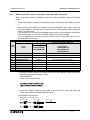
1.3
Options
1.3.1
External Cable
Introduction 1
These external cables contain dedicated wires for communications, DC power supply,
operation switches, grip switch, keylock switch and the emergency stop switch. One of the
cables below is always necessary.
Table 1.3: External Cable
Model Name
F9GT-RHCAB-3M
F9GT-RHCAB-6M
F9GT-RHCAB-10M
Description
37-pin D-sub connector on one side,
- 3M: Cable length is 3m (9' 10")
- 6M: Cable length is 6m (19' 8")
- 10M:Cable length is 10m (32' 9")
F o r 3 7 p in
D -s u b
Note:
When using F9GT-RHCAB-*M external cable, one of the following relay cables is necessary.
1.3.2
Other Options
Order the following options upon necessity.
1) Relay cable for PLC
• F9GT-RHCAB2-150
This cable connects to an FX0/FX0S/FX0N/FX1S/FX1N/FX2N/
FX2NC (with 8-pin MINI DIN connector), and is equipped with
an external cable (with 37-pin D-Sub connector) for power
supply, operation switch and emergency switch.
Cable length is 1.5 m (4' 11").
To PLC
For power supply or
operation switch
Note:
This cable cannot be used for the F943GOT-*BD-RH-E (RS-232C communication
type Handy GOT).
• F9GT-RHCAB3-150
This cable connects to an FX/FX 2C /A/QnA Series PLC or
motion controller (with 25-pin D-Sub connector), and is
equipped with an exter nal cable (with 37-pin D-Sub
c o nn e c to r ) fo r p owe r s u p p ly, o p era tio n sw it ch a n d
emergency switch
Cable length is 1.5 m (4' 11").
To PLC
For power supply or
operation switch
Note:
This cable cannot be used for the F943GOT-*BD-RH-E (RS-232C communication
type Handy GOT).
1-4
Introduction 1
F940GOT Handy Series
• F9GT-RHCAB5-150
This cable connects to a Q Series PLC or motion controller
(with 6-pin MINI DIN connector), and is equipped with an
external cable (with 37-pin D-Sub connector) for power
supply, operation switch and emergency switch
Cable length is 1.5 m (4' 11").
To PLC
For power supply or
operation switch
Note:
This cable cannot be used for the F940GOT-*BD-RH-E (RS-422 communication type
Handy GOT).
2) Protective sheets F9GT-40PSC (5 sheets in 1 set)
Adhere one disposable sheet to the display screen for protection
against dirt and abrasion.
3) Screen creation software
Table 1.4: Screen creation software
Model Name
1.3.3
Description
GT Designer2
SW1D5C-GTD2-E V1.00 or more
(CD-ROM)
FX-PCS-DU/WIN-E
SW0PC-FXDU/WIN-E Version V2.52 or more
(3.5 FD)
GT Designer
SW5D5C-GOTR-PACKE Version 5.05F or more
(CD-ROM)
Spare Parts
1) FX2NC-32BL Battery
This battery is used to back up the alarm history, sampling and
the current time data.
For replacement instructions, refer to chapter 4.
1-5
F940GOT Handy Series
Introduction 1
1.4
Dimensions and Part Names
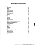
1.4.1
Dimensions and Part Names of Front Panel
Dimensions: mm (inches)
MASS: 0.87 kg (1.91 lbs)
1 5 6 (6 .1 4 ")
5 6 .5
(2 .2 2 ")
b )
i)
1 3 (0 .5 1 ")
W h e n th e o p e r a tio n s w itc h c o v e r is r e m o v e d
a )
h )
1 9 1 (7 .5 2 ")
f)
P O W E R
g )
P O W E R
G R IP S W
G R IP S W
O p e r a tio n s w itc h c o v e r
e )
d )
c )
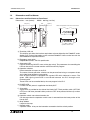
a) Touch key LCD unit
This display unit offers the functions equivalent to those offered by the F940GOT series
display unit. Further information on the standard F940GOT series can be found in the
GOT-F900 Series Operation Manual.
b) Emergency stop switch
Independent contact, 24V DC specification.
c) Grip switch LED
LED for confirming ON/OFF status of the grip switch. The parameters for controlling the
LED can be set in the screen creation software and PLC program.
d) Operation switches
Direct connection to inputs on the PLC.
The name of these operation switches can be personalized using a transparent sheet
and a label sheet offered as accessories.
Each of these switches is equipped with a green LED which indicates its status. The
green LED lighting command is transferred between the PLC through serial
communication.
These LEDs can be controlled the by the user program in the PLC.
e) POWER LED
Lit while 24V DC power is supplied to the Handy GOT.
f) Grip switch
A grip switch is provided on the side of the Handy GOT. The 3-position switch (OFF/ON/
OFF) turns ON when pressed halfway and turns OFF when pressed all the way or when
released.
g) Operation switch name sheet insertion slot
Can be seen when the operation switch cover is removed from the lower portion of the
Handy GOT.
h) Strap holders
Loops for the strap
i) Keylock switch
2-position switch. A key can be inserted or removed to lock the switch position.
1-6
Introduction 1
F940GOT Handy Series
1.4.2
Rear Panel
W h e n th e r e a r c o v e r is r e m o v e d
( e n a la r g e d v ie w )
a )
c )
c )
d )
e )
b )
N o t u s e d
c )
f)
a) Metal hook for mounting on a wall
Offered to mount the Handy GOT on a wall.
b) Hand strap
Adjustable length strap allowing comfortable holding of the Handy GOT.
c) Port for communications signals, the DC power supply, the operation switches and the
emergency switch
d) FX2NC-32BL Battery
Built in to back up data.
For replacement instructions, refer to chapter 4.
e) Port for a personal computer (9-pin D-Sub, male) (for RS-232C communication)
Offered to transfer screen data created using the programming software or using the
two-port interface function.
f) External cable
Offered to connect to a PLC, power supply and operation switches.
1-7
F940GOT Handy Series
Introduction 1
MEMO
1-8
F940GOT Handy Series
2.
Specifications 2
Specifications
Caution
During a communication error (including cable break) while monitoring devices with the
Handy GOT, communication between the Handy GOT and programmable controller CPU is
interrupted and it is impossible to operate the switches or devices in the PLC through the
Handy GOT.
Communication and operation resumes when the Handy GOT system is correctly
configured.
DO NOT configure the emergency stop or safety features to operate through the Handy
GOT, and be sure that there is no adverse consequences in the event of a Handy GOT PLC communications malfunction.
Note:
• Do not lay signal cables near to high voltage power cables or allow them to share the
same trunking duct as noise effects or surge induction are likely to take please. Keep a
safe distance of more than 100 mm from these wires.
• Operate touch switches on the display screen by hand.
DO NOT use excessive force, or attempt operate them with hard or pointed objects.
The tip of a screw driver, pen or similar object, for example, may break the screen.
2-1
F940GOT Handy Series
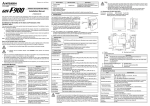
Outside dimensions
The figure below shows the external dimensions of the Handy GOT.
37.5
18
Approx.120
(4.73")
176(6.93")
(0.71")
20
(0.40")
38
(1.50")
10
7
(0.28")
12.7
(0.50")
160(6.30")
GRIP SW
156(6 .15")
10(0.40")
27
51
(2.01")
41
(1.62")
70.7
(2.79")
13
(0.52")
(0.40")
38
(1.50")
27
(1.07")
64.5
64.5
(2.54")
(2.54")
156(6.15")
176(6.93")
58
(2.29")
41
(1.62")
35
(1.38")
29.7
(1.17")
7
(0.28")
7.5(0.30")
78(3.08")
Unit: mm (inches)
Color: Munsell System 0.20G5.17/0.69
Mass: 0.87 kg (1.92 lbs) not including the cable
2-2
(1.48")
88(3.47")
129(5.08")
126(4.97")
210.5(8.29")
24
129(5.08")
191(7.52")
189(7.45")
210.5(8.29")
POWER
15
(0.60")
35.7
(1.41")
10
13
(0.52")
7
(0.28")
(0.95")
27
(1.07")
5
69.5
(2.74")
210.5(8.29")
15(0.60")
70.7
(2.79")
2.1
Specifications 2
F940GOT Handy Series
2.2
Specifications 2
Power Supply Specifications
Table 2.1: Power Supply Specifications
Items
2.3
Specifications
Power Supply Voltage
24V DC, +10% -15%
Power Supply Ripple
200 mV or less
Current Consumption
Ratings: 300 mA at 24V DC
(200 mA at 24V DC when backlight is turned OFF)
Fuse
1.0 A built-in fuse (impossible to change)
Max. Allowable
Momentary Power
Supply Failure period
5 ms; If less than 5 ms, the Handy GOT will continue operation. If 5 ms or
more, the Handy GOT will shut down.
Battery
Built-in, FX2NC-32BL type lithium battery. (Approximately 3 years life)
General Specifications
Table 2.2: General Specifications
Item
Specifications
Operating Temperature
0 ~ 40 °C (32 ~ 104 °F)
Storage Temperature
-20 ~ 60 °C (-4 ~ 140 °F)
Humidity
35 ~ 85% Relative Humidity, No condensation
Vibration Resistance
- intermittent vibration
10 ~ 57 Hz: 0.075 mm Half Amplitude
57 ~ 150 Hz: 9.8 m/s2 Acceleration
Sweep Count for X, Y, Z: 10 times (80 min. in each direction)
Vibration Resistance
- Continuous vibration
10 ~ 57 Hz: 0.035 mm Half Amplitude
57 ~ 150 Hz: 4.9 m/s2 Acceleration
Sweep Count for X, Y, Z: 10 times (80 min. in each direction)
Shock Resistance
147m/s2 Acceleration,
3 times in each direction X, Y, and Z
Noise Immunity
1000 Vp-p, 1micro second, 30 ~ 100 Hz, tested by noise simulator
Dielectric Withstand
Voltage
500 V AC > 1 min., tested between power terminals and ground
Insulation Resistance
5 MΩ > at 500 V DC, tested between power terminals and ground
Ground
Grounding register 100 Ω or less (Class D)
Operating atmosphere
Must be free of lamp black, corrosive gas, flammable gas, or excessive
amount of electroconductive dust particles and must be no direct sunlight.
(Same as for saving)
Protection
IP 54
2-3
F940GOT Handy Series
2.4
Specifications 2
Screen Hardware Specifications
Table 2.3: Screen Hardware Specifications
Items
F94*GOT-SBD-RH-E
F94*GOT-LBD-RH-E
Display Device
STN color liquid crystal display
Resolution
320 × 240 (dot), 40 characters × 15 lines
Dot Pitch
0.36 mm (0.014") Horizontal × 0.36 mm (0.014") Vertical.
Effective Display Size
115 mm (4.53") × 86 mm (3.39"); 6 (5.7 inch) type
Number of Colors
8 colors
Life of liquid crystal
Approximately 50,000 hours (Operating temperature: 25°C / 77°F)
Backlight
Cold cathode tube
Life of Backlight
40,000 hours or more (Operating temperature: 25°C / 77°F)
Touch Keys
Maximum 50 touch keys / screen, 20 × 12 matrix
Interface
With PLC
F940GOT-*BD-RH-E: RS-422
F943GOT-*BD-RH-E: RS-232C
With
personal
computer
RS-232C
White and Black
Number of Screens
User screen: 500 screens or less
System screen: Allocated screens No. 1001-1030.
User Memory
Flash memory 512 KB (built-in)
• Bright dots (always lit) and dark dots (unlit) may appear on a liquid crystal display panel. It is
impossible to completely avoid this symptom, as the liquid crystal display comprises of a
great number of display elements. Flickers may be observed depending on the display color.
Please note that these dots appear due to its characteristic and are not caused by product
defect.
• When the same screen is displayed for a long time, an incidental color or partial discoloration is generated on the screen due to heat damage, and it may not disappear.
• Using the GOT Backlight OFF function can prolong the life of the backlight. For details on
the Backlight OFF function, refer to the following.
GOT-F900 Series OPERATION MANUAL/GOT-F900 Series OPERATION MANUAL
[GT Designer2 Version]
2.5
Switch Specifications
Table 2.4: Switch Specifications
Item
Description
Operation switch
N/O contact × 4 points, 10mA/24V DC
(Operation life time: Approximately 1,000,000 times)
Emergency stop switch
2 N/C contacts, 1A/24V DC (resistive load), independent wiring
(Operation life time: Approximately 100,000 times)
Keylock switch
2-position, 1A/24V DC (resistive load), independent wiring
(Operation life time: Approximately 100,000 times)
Grip switch
3-position (OFF/ON/OFF), 2 N/O contacts, independent wiring
1A/24V DC (resistive load)
(Operation life time: Approximately 500,000 times)
2-4
F940GOT Handy Series
3.
Installation 3
Installation
This section describes the installation of the Handy GOT.
All the specifications should be thoroughly understood before performing the installation.
Further information about selecting and wiring the cables can be found in the GOT-F900
SERIES HARDWARE MANUAL (CONNECTION).
Caution:
Rewire all phases of the power source, before installation or wiring work in order to avoid
electric shock or damage to the product.
3.1
Installation Method
Note:
• Do not mount the GOT in an environment that contains dust, soot, corrosive or conducive
dust, corrosive or flammable gas, or expose the unit to high temperatures, dew
condensation, direct sunlight, rain and wind or impact and vibration.
If the GOT is used in such an environment, electrical shock, fire, malfunction, damage or
deterioration of the unit may occur.
• Make sure that the power is turned off, before connecting any cables. Connections
should be made securely. Poor connections may cause malfunction.
3.1.1
Holding
When holding the Handy GOT for operation, place your hand through the hand strap provided
on its rear face. You can adjust the length of the hand strap.
H a n d s tra p
3-1
F940GOT Handy Series
3.1.2
Installation 3
Wall Mounting
When mounting the Handy GOT on a wall, use the metal hook provided on its rear face.
M e ta l h o o k fo r m o u n tin g o n w a ll
W a ll fa c e
B 5 m m (0 .2 0 ")
B 1 0 m m (0 .3 9 ")
The wall fixture should be able to support the weight of the main unit (approximately 0.87 kg/
1.91 lbs) and a load of approximately 1 ~ 3 kg (2.20 ~ 6.61 lbs) which varies depending on the
communication cable length. Take this into consideration and attach a suitable metal fixture on
the wall.
3.1.3
Flat Surface Mounting
When using the Handy GOT on a flat surface, such as a desk or shelf, keep the Handy GOT
parallel to the surface so that it does not drop. Also, fix the communication cable to the desk.
F ix th e e x te r n a l c a b le w h e n
in s ta llin g o n a fla t s u r fa c e .
3-2
F940GOT Handy Series
3.1.4
Installation 3
Hand/Shoulder Strap
A hand/shoulder strap (prepared by the user) to help prevent accidental drops can be attached
to the loops.
S tra p
(p re p a re d b y th e u s e r)
L o o p s
Dimensions of the loop
5 (0.2")
14 (0.55")
Dimensions: mm (inches)
3-3
F940GOT Handy Series
3.2
Installation 3
Outline of Connection
This section explains the connection configurations for the Handy GOT.
F u r t h e r i n fo r m a t io n c a n b e fo u n d in G OT-F 9 0 0 S E R IE S H A R DWA R E M A N UA L
(CONNECTION).
Handy GOT
External cable
Cable to PLC
Wiring inside panel
Wiring outside panel
F9GT-RHCAB
F9GT-RHCAB2
To PLC
For power supply and
operation switches
F9GT-RHCAB3
To PLC
PLC
For power supply and
operation switches
Prepared by user
To PLC
For power supply and
operation switches
Supplied from external
power supply
24V DC
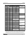
3.2.1
Signal Allocation of Connector
The signal allocation within the connector of the external cable are shown below.
Arrangement of color
F9GT-RHCAB-
M
37-pin D-Sub, male
1
{/{
a)
20
{/{
{/{
19
b)
{/{
37
d)
c)
{/{
e)
3-4
F940GOT Handy Series
Installation 3
Table 3.1: Name of communication lines, power supply and switches
External Cable (F9GT-RHCAB-*M)
Pin No. Color of wire
1
Signal Name
Description
Arrangement F940GOT Handy F943GOT Handy
of color
(RS422)
(RS232C)
Shield
FG (shield)
Frame ground
2
Yellow/Blue
a)
TXD+ (SDA)
SD (TXD)
3
Yellow/Red
a)
TXD- (SDB)
ER (DTR)
4
White/Blue
a)
RTS+ (RSA)
RD (RXD)
5
White/Red
a)
RTS- (RSB)
DR (DSR)
6
Gray/Blue
a)
RXD+ (RDA)
RS (RTS)
7
Gray/Red
a)
RXD- (RDB)
CS (CTS)
8
Orange/Blue
a)
CTS+ (CSA)
NC
9
Orange/Red
a)
CTS- (CSB)
NC
10
Orange/Red
c)
SG
Signal ground
11
−
−
NC
Not used
12
White/Red
b)
SW-COM
13
Gray/Blue
b)
SW1
14
Gray/Red
b)
SW2
15
Orange/Blue
b)
SW3
16
Orange/Red
b)
SW4
17
−
−
NC
18
Gray/Blue
d)
19
Gray/Red
d)
20
Pink/Red
d)
ES1-1
21
Pink/Blue
d)
ES1-1
22
Orange/Red
e)
ES1-2
23
Orange/Blue
e)
ES1-2
24
White/Red
d)
DSW-1
25
White/Blue
d)
DSW-1
26
Yellow/Red
d)
DSW-2
27
Yellow/Blue
d)
DSW-2
28
White/Blue
b)
KSW-C
29
Yellow/Red
b)
KSW-1
30
Yellow/Blue
b)
KSW-2
31
Pink/Red
b)
Spare SW
32
Pink/Blue
b)
Spare SW
33,34,35
−
−
NC
36
Orange/Blue
d)
37
Orange/Red
d)
DC24V G
DC 24V+
Note 1
COM for Operation switches
Operation switches
Not used
24V DC power supply "-"
Emergency stop switch
Grip switch
Common for keylock switch
Keylock switch
Spare
Not used
24V DC power supply "+"
Note 1:
These are signals for communication with the PLC. When connecting to a port other than
the programming port of the FX, A, QnA or Q series PLC, refer to the manual of the
connected module. Also use a relay cable. For relay cable details, refer to section 1.3.2.
3-5
F940GOT Handy Series
3.3
Installation 3
Installation of External Cable
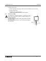
This section explains the installation procedure for the optional external cable to the Handy
GOT main unit.
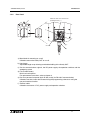
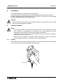
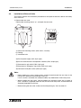
1) Remove the rear cover
Remove the mounting screws "a)", and open the rear cover.
b ) (D )
(B )
c )
(A )
(C )
(E )
N o te
a )
a) Rear cover mounting screws, (M3 × 8mm, 4 screws)
b) Packing
c) Installation hole
(A)Port for power supply (CN1; 8-pin type)
(B)Port for communication and operation switches (CN2; 20-pin type)
(C)Connector for grip switch (CN4; 5-pin type)
(D)Connector for emergency stop switch (CN5; 4-pin type)
(E)Connector for keylock switch (CN6; 3-pin type)
Note:
• Never remove any screw (among seven screws located around the rear face of the
Handy GOT) other than the mounting screws "a)".
If such a screw is removed, the waterproof ability may deteriorate or failure may occur.
• When installing the rear cover, securely tighten the mounting screws with a torque of
0.49 ~ 0.68 Nm. If tightened more than this, the rear cover may crack, and the water and
dustproof proprieties may be lost.
• Before closing the rear cover, make sure that the packing "b)" has not come off.
3-6
F940GOT Handy Series
Installation 3
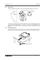
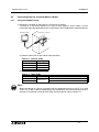
2) Connect the external cable
Insert the external cable into the installation hole "c)" of the Handy GOT, and connect it to
"(A)", "(B)", "(C)", "(D)" and "(E)".
W h e n p u s h in g th e c a b le th r o u g h ,
m a k e e a c h c o n n e c to r fa c e d o w n w a rd s .
3) Tighten the hexagon nut.
P a c k in g
H e x a g o n n u t fo r
c a b le m o u n tin g
H e x a g o n n u t
fo r s e c u r in g c a b le
2 3 .8 m m
Make sure to tighten the hexagon nut for cable
mounting with a sufficient force to avoid
loosening.
As guideline, tighten it until the packing is
crushed by 0.5 mm (0.02") or more.
(0 .9 4 ")
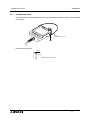
4) Pull lightly on the cable until excess cable is with drawn from inside the unit.
P u llin g d ir e c tio n
5) Securely tighten the hexagon nut so that the cable will not come out and the waterproof
integrity is maintained.
N o te
Note:
As guideline, make sure that the clearance is 3.5 mm (0.14") or less.
3-7
F940GOT Handy Series
Installation 3
6) Attach the rear cover
a) Before replacing the rear cover, make sure that the packing b) has not come off.
b) Attach the rear cover.
c) Tighten the four mounting screws.
Make sure the tightening torque is 0.49 to 0.68 N⋅m.
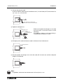
3.3.1
Caution for CE EMC
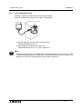
For compliance to CE EMC regulations it is necessary to add a
ferrite filter on the external cable for F940GOT-*BD-RH-E or
F943GOT-*BD-RH-E.
The filter should be attached as shown with the filter surrounding
the external cable.
The recommended ferrite filter is the TDK ZCAT2436-1330A-MBK or equivalent.
P O W E R
G R IP S W
1 1 0 m m
( 4 .3 3 " o r le s s )
F e r r ite filte r
3-8
F940GOT Handy Series
Installation 3
3.4
Processing Panel for a Control Box or Cabinet
3.4.1
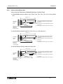
Using the F940GOT Handy
1) Installing a connector on the panel of a control box or cabinet.
Connect to an FX/A/QnA Series PLC using a relay cable as shown below. Further
information regarding applicable PLCs can be found in GOT-F900 Series Hardware Manual.
C o n tr o l b o x o r c a b in e t
F 9 4 0 G O T H a n d y
P O W E R
G R IP S W
P L C
b )
a )
a) External cable (with 37-pin D-Sub, male connector)
Table 3.2: External Cable
Model Name
Length
F9GT-RHCAB-3M
3m (9' 10")
F9GT-RHCAB-6M
6m (19' 10")
F9GT-RHCAB-10M
10m (32' 9")
b) Relay cable for connection to PLC
Table 3.3: Relay Cable
Model Name
F9GT-RHCAB2-150
F9GT-RHCAB3-150
Length
1.5m (4' 11")
Applicable
FX Series (FX0, FX0S, FX0N, FX1S, FX1N, FX2N, FX2NC)
FX (FX, FX2C), A, QnA Series
Note:
When connecting to a port or unit other than the programming port of an FX, A or QnA
series PLC, make a cable corresponding to the configuration of the communications port in
question. For allocation of Handy GOT communication signals, refer to section 3.2.
3-9
F940GOT Handy Series
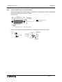
3.4.2
Installation 3
Using the F943GOT Handy
Installing a connector on the panel of a control box or cabinet
Connect a Q Series PLC using a relay cable as shown below.
F 9 4 3 G O T H a n d y
P O W E R
G R IP S W
C o n to r o l b o x o r c a b in e t
b )
P L C
a )
a) External cable (with 37-pin D-Sub, male connector)
F9GT-RHCAB-3M (3m /9' 10")
b) Relay cable for connection to Q series PLC
F9GT-RHCAB5-150 (1.5m /4' 11") for Q series PLC
Note:
When connecting to a port or unit other than the programming port of a Q series PLC, make
a cable corresponding to the configuration of the communications port in question. For
allocation of Handy GOT communication signals, refer to section 3.2.
3-10
F940GOT Handy Series
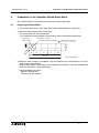
3.4.3
Installation 3
Pinouts for the Relay Cable
Refer to the GOT-F900 Serise HARDWARE MANUAL [CONNECTION].
1) F9GT-RHCAB2-150 relay cable for the FX (FX0, FX0S, FX0N, FX1S, FX1N, FX2N, FX2NC) Series
PLC
1 .5 m
(4 ' 1 1 ")
T o th e p o w e r s u p p ly a n d o p e r a tio n s w itc h e s .
A n a m e la b e l is a tta c h e d to th e tip o f e a c h
u n tie d w ir e .
C o n n e c te d
e x te rn a l
c a b le
3 7
c o
(p
m
p in
n n e
a n e
o u n
D - S u b , fe m a le
c to r
l fa c e
tin g ty p e )
T o F X s e r ie s P L C
0 .5 m
(1 ' 7 ")
( 8 - p in M IN I D IN
F o r g ro u n d
( g r o u n d in g r e s is ta n c e 1 0 0 9
c o n n e c to r)
o r le s s , c la s s D )
2) F9GT-RHCAB3-150 relay cable for FX (FX, FX2C), A, QnA series PLC
1 .5 m
(4 ' 1 1 ")
T o th
A n a
u n tie
T o F
s e r ie
C o n n e c te d
e x te rn a l
c a b le
3 7
c o
(p
m
p in
n n e
a n e
o u n
D - S u b , fe m a le
c to r
l fa c e
tin g ty p e )
0 .5 m
(1 ' 7 ")
e p o w
m e la b
d w ir e
X (2 5 p
s P L C
.
e r s u p p ly a n d o p e r a tio n s w itc h e s .
e l is a tta c h e d to th e tip o f e a c h
in D - s u b c o n n e c to r ) , A a n d Q n A
F o r g ro u n d
( g r o u n d in g r e s is ta n c e 1 0 0 9
o r le s s , c la s s D )
3) F9GT-RHCAB5-150 relay cable for Q series PLC
1 .5 m
(4 ' 1 1 ")
T o th e p o w e r s u p p ly a n d o p e r a tio n s w itc h e s .
A n a m e la b e l is a tta c h e d to th e tip o f e a c h
u n tie d w ir e .
C o n n e c te d
e x te rn a l
c a b le
3 7
c o
(p
m
p in
n n e
a n e
o u n
D - S u b , fe m a le
c to r
l fa c e
tin g ty p e )
T o Q
0 .5 m
(1 ' 7 ")
s e r ie s P L C
( 6 - p in M IN I D IN
F o r g ro u n d
( g r o u n d in g r e s is ta n c e 1 0 0 9
c o n n e c to r)
o r le s s , c la s s D )
3-11
F940GOT Handy Series
3.4.4
Installation 3
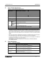
Panel Cut Dimensions for the Relay Cable
When mounting the relay cable connector on the panel of a control box or cabinet, prepare the
panel of the control box or cabinet as follows.
Panel cut size
63.5 (2.5")
59.1 (2.33") or more
2-φ3.2±0.1
(0.13"±0.004")
indicates the cut area.
11.4 (0.45") or more
Unit: mm (inches)
4-R3.4 (0.13")
10°
(Panel thickness: 0.8 ~ 1.3mm / 0.03" ~ 0.05")
Insert a jack socket into the hole shown above, and tighten it with M3 (0.12") nuts.
M 3 (0 .1 2 ")
J a c k s o c k e t
4 .8 (0 .1 9 ")
M 3 (0 .1 2 ")
J a c k s o c k e t
C o n n e c te d to
e x te r n a l c a b le
P a n e l fa c e o n
w h ic h c a b le
is m o u n te d
N u t (M 3 )
C a b le s id e
3-12
F940GOT Handy Series
4.
Preparation of the Operation Switch Name Sheet 4
Preparation of the Operation Switch Name Sheet
This section explains how to prepare the operation switch name sheet.
Preparing the Name Sheet
1) Use a name sheet and an OHP sheet (transparent sheet) offered as accessories.
2) Write the switch names on the name sheet.
The name sheet is of actual dimensions.
If you would like to make additional name sheets, refer to the following dimensions.
K e y c e n te r
( p r in t c e n te r )
D ia m e te r = 1 7 ( 0 .6 7 " )
: E ffe c tiv e r a n g e fo r c h a r a c te r s
C
2
.0
(0
S h e e t in s e r tio n d ir e c tio n
2 0
0 .7 9
+ 0
-1
+ 0
-0 .0 4
1 0
(0 .3 9 ")
4.1
)
8"
1 2
(0 .4 7 ")
2 2
(0 .8 7 ")
2 2
2 2
(0 .8 7 ")
(0 .8 7 ")
9 6 (3 .7 8 ")
(1 8 )
(0 .7 1 ")
U n it : m m
( in c h e s )
3) When the work in step b) is completed, copy the contents of the name sheet on to an OHP
sheet using a copy machine.
When using a different OHP sheet, use the following type. Make sure that the selected OHP
sheet can be used in a copy specification.
[Recommended OHP sheet]
Material: Polyester film
Thickness: 0.1mm (0.004")
4-1
F940GOT Handy Series
4.2
Preparation of the Operation Switch Name Sheet 4
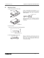
Attaching the Sheet
1) Remove the operation switch cover
O p e r a tio n s w itc h
c o v e r
*1
*3
Inser t a screwdriver into the gap *1 or *3
between the operation switch cover and the
main unit, then slowly push the operation
switch cover up.
O p e r a tio n s w itc h
c o v e r
*2
S c r e w d r iv e r
*3
*1
When either side *1 or *3 comes off, pull the
operation switch cover in the sliding direction
to remove it.
*2
S lid in g d ir e c tio n
2) Insert the sheet
Insert the name sheet into the following position.
N a m e s h e e t in s e r tio n s lo t
3) Attach the operation switch cover
L e t it b e s lig h tly w a r p e d .
*1
*3
Align the operation switch cover with the
protrusion *1 or *3 shown in the figure in the
step 1), then attach the operation switch cover
while flexing it slightly.
4-2
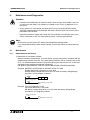
F940GOT Handy Series
5.
Maintenance and Diagnostics 5
Maintenance and Diagnostics
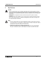
Cautions:
• Correctly install the battery for memory backup. Never charge, disassemble, heat, burn
or short-circuit the battery. If the battery is handled in such a way, an explosion or fire
may occur.
• Always power OFF and remove the Handy GOT from any mounting location before
starting the replacement of the backlight and battery. Electric shock may occur if these
precautions are not taken.
• Never disassemble or modify the Handy GOT. Disassembly or modification may cause
failure, malfunction or fire. For repair, please contact a service representative.
Note:
Make sure to turn the power OFF before connecting/disconnecting cables.
If you connect/disconnect cables while the power is turned ON, failure or malfunction may
occur.
5.1
Maintenance
5.1.1
Replacement of the Battery
1) Notification of Low Battery Voltage
When the battery voltage drops, a control device (system information) assigned with the
programming software turns ON. The control device interlocks with an auxiliary relay in the
PLC. It is recommended to provide a lamp while utilizing the output of the PLC so that voltage drop can be monitored outside the Handy GOT.
For details of control devices, refer to the GOT-F900 SERIES OPERATION MANUAL.
Example: SW
D5C-GOTR-PACKE or SW
D5C-GTD2-E is used
System information write device is set to D20
D24 b3: Battery voltage drop (which turns on when the battery voltage drops)
Use D24 in a PLC program as follows.
M8000
M0V D24 K2M20
Battery voltage drop
M23
Y
Indication outside PLC
Example: FX-PCS-DU/WIN-E is used
Top control device No. is set to M0
M6: Battery voltage drop (which turns ON when the battery voltage drops)
Use M6 in a PLC program as follows.
Battery voltage drop
M6
Y
Indication outside PLC
5-1
F940GOT Handy Series
Maintenance and Diagnostics 5
2) Procedure for Replacing the Battery
The battery can back up the alarm history, sampling and the current time for approximately
one month after the control device for the battery voltage drop turns ON. When the control
device (system information) turns ON, replace the battery (FX 2NC -32BL) as soon as
possible.
The screen data is stored in the flash memory. Even if the battery power is completely
depleted, the screen data remains in the flash memory.
a) Turn off the power of the Handy GOT.
b) Open the small window of the rear panel.
c) Remove the existing battery from the holder and
disconnect it.
d) Within 30 seconds, connect a new battery.
F X 2 N C -3 2 B L
e) Insert the new battery into the holder and close the
small window.
Battery life: Approximately 3 years
5.2
Diagnostics
5.2.1
Preliminary Check
1) Check "POWER LED"
If the POWER LED is OFF, check cable(s), and check if the 24V DC power source capacity
is sufficient. (Refer to chapter 2.2)
2) Check display
If the display screen is dark, adjust "LCD CONTRAST" in "SET-UP MODE".
If the display screen remains dark even after adjustment, replace the backlight. Please
contact a service representative for more information. (Refer to chapter 2.2)
3) Check setting "PLC TYPE" in "SET-UP MODE"
If this setting is incorrect, Handy GOT cannot communicate with the PLC correctly. (Refer to
chapter 3)
5-2
F940GOT Handy Series
5.2.2
Maintenance and Diagnostics 5
When an operation switch or emergency stop switch does not operate
When an operation switch or emergency stop switch does not operate, check the following
points.
• Check whether external cables are connected correctly to the Handy GOT. (Refer to chapter
3)
• While pressing and holding an operation switch or emergency stop switch, check the
conduction between the wires (pins or terminal blocks) of the external cables and relay
cable in the table below.
If no conduction is confirmed, wire breakage or poor contact may be present in the external
cable or relay cable, or the circuits inside the Handy GOT may be damaged.
If it is suspected that the circuits inside the Handy GOT are damaged, consult with a
Mitsubishi Electric distributor.
Signals whose conductivity can be checked
External cable*1
Switch
name
Signal
name
F9GT-HCAB-3M
F9GT-HCAB-10M
External cable F9GT-HCAB-
M
+
Relay cable*2
F9GT-HCAB2-150
F9GT-HCAB3-150
F9GT-HCAB5-150
SW1
SW-COM and SW1
12 and 13
White/Red and Gray/Blue (B)*3
SW2
SW-COM and SW2
12 and 14
White/Red and Gray/Red (B)*3
SW3
SW-COM and SW3
12 and 15
White/Red and Orange/Blue (B)*3
SW3
SW-COM and SW4
12 and 16
White/Red and Orange/Red (B)*3
ES1-1 ES1-1 and ES1-1
20 and 21
Pink/Red and Pink/Blue (D)*3
ES1-2 ES1-2 and ES1-2
22 and 23
Orange/Red and Orange/Blue (D)*3
KSW-1 KSW-COM and KSW-1
28 and 29
White/Blue and Yellow/Red (B)*3
KSW-2 KSW-COM and KSW-2
28 and 30
White/Blue and Yellow/Blue (B)*3
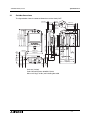
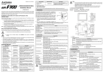
*1 Connect an external cable to the Handy GOT, press and hold each switch, then check
the conduction between the pins or wires.
F9GT-HCAB-M
37-pin D-sub, male connector
1
19
20
37
*2 Connect an external cable and relay cable to the Handy GOT, press and hold each
switch, then check the conduction between wires.
*3 Arrangement of color type.
Arrangement of color (Color type)
Type A {/{
Type B {/{
Type D {/{
Type E {/{
Type C {/{
5-3
F940GOT Handy Series
5.2.3
Maintenance and Diagnostics 5
When the LCD screen is dark
When the display is dark, adjust the brightness selecting "MODE SELECT MENU SCREEN" "OTHER MODE" - "SET-UP MODE" - "LCD CONTRAST". If the screen remains dark even
after adjustment, it is recommended to replace the backlight. For replacement of the backlight,
consult with a Mitsubishi Electric distributor.
For the details of the utility function, refer to the GOT-A900 SERIES OPERATING MANUAL
(EXTENTION FUNCTIONS/OPTIONAL FUNCTIONS).
5.3
Check Error Messages
The table below shows the list of error messages displayed during manipulation or operation.
Check the contents, and take proper action.
Table 5.1: Check Error Massages
Error message
Description
Action
CAN NOT WRITE
PLC MEMORY.
The PLC is running in EPROM mode.
Or the write-protect switch of the
EEPROM is set to ON.
Run the PLC in RAM mode. Or set the
write-protect switch of the EEPROM to
OFF.
PLC IS RUNNING.
A personal computer is attempting to
write a program using "DATA
Stop the PLC. Or enter the correct
TRANSFER” in "OTHER MODE" while
entry code.
the PLC is running. Or an entry code
has been registered.
DATA IS NOT
FOUND.
There are no screen data or data files.
Create the data using the programming
software.
Screen No. 0 (FX-PCS-DU/WIN-E) or
screen No. 1 (GT Designer) does not
DISPLAY SCREEN
exist.
IS NOT AVAILABLE.
When a screen is to be changed over,
there is no destination screen.
Create screen No. 0 or 1.
Or change the changeover destination
screen, or create the corresponding
screen.
5-4
HARDWARE MANUAL
F940GOT Handy Series (F94*GOT-*BD-RH-E)
HEAD OFFICE: TOKYO BUILDING, 2-7-3 MARUNOUCHI, CHIYODA-KU, TOKYO 100-8310 JAPAN
HIMEJI WORKS: 840, CHIYODA CHO, HIMEJI, JAPAN
MODEL
F940RH-HW-E
MODEL CODE
09R811
JY992D99901C
(MEE)
Effective Sep. 2008
Specifications are subject to change without notice.