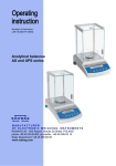
1
Mass comparators – WAX series WAX 210/KO WAX 510/KO WAX 2100/KO WAX 5100/KO MANUFACTURER OF ELECTORNIC WEIGHING INSTRUMENTS RADWAG 26 – 600 Radom, Bracka 28 Street, POLAND phone +48 48 38 48 800, phone/fax. +48 48 385 00 10 Sales Department +48 48 366 80 06 www.radwag.com May 2007 2 Contents 1. UNWRAPING THE COMPARATOR ................................................................... 4 2. START THE COMPARATOR UP ...................................................................... 10 3. APPROPRATION .............................................................................................. 11 4. DESCRIPTION OF THE COMPARATOR - display .......................................... 12 5. USER MENU ..................................................................................................... 13 6. COMPARISON .................................................................................................. 21 6.1. Log-in function ............................................................................................ 22 6.2. Method of measurements ........................................................................... 25 7. CALIBRATE / ADJUST ..................................................................................... 27 7.1. External calibration ..................................................................................... 28 7.2. Calibration report printout ........................................................................... 28 8. SETTING PRINTOUTS FOR GLP PROCEDURES........................................... 30 9. SETTING TIME AND DATE .............................................................................. 30 10. SETTING THE PARAMETERS ....................................................................... 34 10.1 Setting filter................................................................................................ 34 10.2. Mediane filter setting................................................................................. 34 10.3 Set the display refreshing time .................................................................. 35 10.4 Set autozero working ................................................................................. 35 10.5. Last digit ................................................................................................... 35 10.6. Negative ................................................................................................... 35 11. FUNCTIONS IN USING RS 232 PORT ........................................................... 36 12. PRINTOUTS .................................................................................................... 37 13. ACCESS TO MASS UNITS ............................................................................. 37 14. SETTING ACCESSIBILITY OF THE WORK MODES..................................... 38 15. OTHER PARAMETERS .................................................................................. 40 16. USING WORK MODES ................................................................................... 42 16.1. Standard deviation for comparator ........................................................... 42 16.2. Statistics ................................................................................................... 48 17. KINDS OF PRINTOUTS .................................................................................. 50 17.1. Standard printout ...................................................................................... 50 17.2. Non-standard printout ............................................................................... 51 18. COOPERATION WITH PRINTER OR COMPUTER........................................ 57 19. LIST OF COMMUNICATIONS COMPUTER - COMPARATOR ...................... 58 20. TECHNICAL PARAMETERS .......................................................................... 60 21. COMMANDS ABOUT ERRORS ..................................................................... 64 3 1. UNWRAPING THE COMPARATOR 1.1. The comparator WAX 2100/KO Take the comparator out of the box. Remove the protection foam. Take all components out of the box. THE COMPONENTS INSTALATION FOR THE COMPARATOR STEP I Unscrew four bolts on the sides of casing, then carefully remove casing. 4 STEP II REMOVE CARRYING PROTECTION. Unscrew and remove carefully holding down block 1. Next unscrew and remove carefullybase block 2, 3. Disassembled protections keep together with packing. 5 STEP III Tighten up balance weight to weighbeam. 6 STEP IV Unscrew and remove carefullybase block 4 (2 pieces) and assembly casing of comparator. 7 STEP V Instalation glass draft shield with 3 sliding doors 8 STEP VI - STARTING Assembly pan 1and load 2kg weight, according to draving above. After assembling all components, slide the glass doors shut and plug in the balance. The jack plug is in the rear of the balance. 9 2. START THE COMPARATOR UP 2.1. Conditions of proper usage Set up the mass comparator in a conditioned room kept at a constant temperature (max. allowable fluctuation: ΔT<±0.5°C/h). When choosing a location to set up mass comparator, observe the folowing so that you will be able to work with added and accurace: − Set the comparator on stable table, far from vibrations − The comparator should be replaced far from draughts and air breeze. − The comparator should be in stable temperature and humidity room − The comparator should be replaced far from sources of − Temperature in the room +18°C ÷ +30°C − If the static electricity has influence on the comparator indications it base should be earthed. Earthing screw is in the rear part of the comparator base. − The comparator should be replaced in leveled position During a weighing operation, avoid moving around in the room where the mass comparator in set up. 2.2. Set level up The comparator should be leveled. The correct leveling is shown on the level indication installed at rear of the comparator. 2.3 Warming up Before measurements user should wait untill the comparator reaches temperature stabilization. It is warming up time. For comparators WAX, warming-up time is about 4 hour. This periods refers to the comparators which ware in surrounding temperature (work) before start weighing. If the WAX comparators are kept in, lower temperature before weighing the warming-up time is about 12 hours. During warm-up stabilization, the indications can change. 10 3. APPROPRATION The comparators are used to do precise measurements in laboratories. It is possible to do the zero function in all measure range. The comparator weights in following units: Measure units Apart from mass comparrision in various measure units the comparator also: − − standard deviation creates statistics Measure units and particular functions can be inaccessible for user. It is possible to adapt the comparator to individual needs and access functions and units which are necessary at this moment. It is possible to define accessible or noo-accessible in user menu and it is described in further part of the manual. 11 4. DESCRIPTION OF THE COMPARATOR - display Display comparator 1. 2. 3. 4. 5. 6. 7. 8. load mass and quantity of pieces measure unit the result is stable line of max range of the comparator work mode date time precise ZERO 4.2. Keyboard Each key is dual-function key. Particular function can be done through. User also can move in the comparator menu. Switches the display off. Function key. Selects the work mode Changes measure units Sends information to external instrument (PRINT) or confirms parameter value or function (ENTER). Sets indication to zero 12 4.3 Connections 1. 2. 3. 4. power adapter socket PS keyboard connector RS 232 port additional display socket Sockets of the comparator 5. USER MENU There are 9 groups in user menu. Each group is named by P letter. Name and contents of each group is presented below. P1 Calibration 01 External calibr 02 Kalibr 03 Calibr time 04 Report printout |********| | * * * * * *0.3 | | * * * * * *0.3 | | * * * * * *0.1 | Function both 3 hours on P2 GLP 01 User 02 Project 03 Time printout 04 Date printout 05 User printout 06 Project printout 07 Printout Id 08 Calibration printout | Nowak Jan | | AR – 65/04 | | * * * * * *0.0 | | * * * * * *0.0 | | * * * * * *0.0 | | * * * * * *0.0 | | * * * * * *0.0 | | * * * * * *0.0 | off off off off off off P3 Date/Time 01 Form date 02 Form time 03 Time 04 Date 05 Display time 06 Display date | * * * * * * * 0 | D/M/R | * * * * * * * 0 | 24 hours | * * * * * * * * | Function | * * * * * * * * | Function | * * * * * * * 1 | on | * * * * * * * 1 | on 13 P4 Readout 01 Filter 02 Med. filter 03 Disp. refresh 04 Autozero 05 Last digit 06 Negative | * * * * * * * 3 | normal | * * * * * * * 3 | normal | * * * * * * * 1 | 0.1 s | * * * * * * * 1 | on | * * * * * * * 1 | always | 1 | disabled P5 RS - 232 01 Transm. speed 02 Parity 03 Data bits 04 Stop bits 05 Transm data 06 Aut. printout 07 Interval 08 Min. mass 09 Print stab |*******1| |*******0| |*******2| |*******1| |*******0| |*******0| |*******1| |*******4| |*******1| P6 Printout 01 Numer Print 02 Print 1 start 03 Print 1 stop 04 Print 2 start 05 Print 2 stop ... . . . . . . . . . . 10 Pr. Edit 11 String 1 11 String 2 ... . . . . . . . . . . 89 String 80 | * * * * * * * 0 | standard |*******1| |*******1| |*******1| |*******1| |*******0| | * * * * * * * * | function |*******1| |*******4| |*******1| |*******0| P7 units 01 Grams 02 Miligrams 03 Newtons 04 user unit 05 factor unit |*******1| |*******1| |*******0| |*******0| |*******1| P8 Work modes 01 Std. Dev. 02 Statistics 03 Power on mode | * * * * * * * 1 | enabled | * * * * * * * 1 | enabled | * * * * * * * 1 | Std. Dev. 14 4800 none 8 bits 1 bit none none * 0.1 s 10 d enabled enabled enabled disabled disabled P9 Globals 01 Ustawieno ID 02 Print Aut. ID 03 Signal 04 Language 05 Backlight 06 Contrast 07 Screen server 08 Temperature 09 Comparator numbe 10 Program number 11 Printout par. 12 Parameter reception 13 Password protection |******** |*******0 |*******1 |*******1 |*******1 |******** |*******0 |******** | 114493 * * | MBCxxx |******** |******** |******** | function | off | enabled | english | on | function | enabled | function | | | function | function | function Parameters in user menu are: • functional – for particular activity eg. the comparator calibration • selectable – selects one of few values from the comparator memory • noted – changes sets in the comparator memory eg. Date, time, user number, texts 15 Menu – graphic version Press the F key to display main menu of the comparator (display I). Select the submenu whose content is displayed after pressing the F key (display II). Menu 1 – main menu number 2 – indication of the function selection 3 – function name 4 – currently used function 5 – submenu number 6 – submenu name 7 – attribute of the menu 8 – value of the attribute 16 5.1. Move in user menu User moves in the menu by - the comparator keyboard - PS keyboard, - Communicates from computer to the comparator 5.1.1. The comparator keyboard enter main menu move down in the menu move up in the menu selects submenu which is activated. Submenu contents is presented on the display move one level up to main menu Resignation parameter changing 5.1.2. Return to weighing function Introduced changes are recorded after return to weighing mode and confirm changes. Press the ESC key many times. If following question appears on the display press: ENTER – confirm or ESC – cancel Return to weighing 17 5.1.3. PS computer keyboard Each key on the comparator keyboard has its equvivalent on the PS keyboard: - for functions Description keyboard Switch on/off the comparator display Move to the comparator menu Selects work mode Selects measure unit PRINT TARE - for direction keys Move up Move to level up Sets selected parameter Move down 18 - for ENTER / PRINT keys and ESC Confirm changes Cancel and leave function without changes 5.1.4. By means of virtual keyboard through RS 232 Most of the functions are done by the comparator desk or PS keyboard. They are aslo done by sending orders computer – comparator. This commands enables to move in the comparator manu and control the comparator work. The list of the commands is at the end of the manual. 5.2 User menu The menu is presenting in p. 5. Press the F key in weighing level. Main menu is presenting on the display. Select the submenu, which is modificated. Main menu – submenu selection If the menu will be modificated, press the F key. Selected menu appears on the display. Select what will be changed in this submenu (activate). Select through keys presented on the Draw above. Press the F key. 19 Reaction of the comparator: - Activity of the comparator (eg. the comparator calibration) is done for submenu described as Function Attribute activation for submenu which is indicated (digit flashing means the value can be changed and some signs can be written) Tthe comparator submenu 20 6. COMPARISON Following conditions must be fulfilled to get reliable results: - Stable temperature - Stable ground - Proper parameters for external conditions Before measurements or for essential changes of the external conditions (if the temperature changes more than 0,5°C/h) calibrate the comparator in accordance with p. 7. Before measurements load the pan and check if the comparator show in down left corner of the display „precise zero” – displayed (only if the parameter P4 06 Autozero has the value 1: yes) and check is displayed in right up corner of if the measurement is stable – the display. If the comparator does not show zero press the key If the conditions are unfavourable (no stable result) lines appear on the display. After settled time the comparator returns to weighing mode without set up to zero. In this case wait untill the conditions stabilize and press Esc again By the Units key select measure unit. Put the load on the pan and after stabilization read out the result. If measure unit user wants to use is not displayed during pressing the Units key check if it has access attribute. The indication can be set to zero many times. Sum of loads noted in the comparator memory cannot be higher than max capacity. Betwenn following measurements do not unpluged the comparator. The comparator should be switched off by the ON/OFF key. After pressing the key again the comparator is ready to work without warm stabilization. 21 6.1. Log-in function The operator has own access code to internal menu. The password system is defined by administrator. Password can contain max 6 digits. The comparator program enables to declare: • One administrator who is authorised to use all sets and programme functions, change the passwords – own and user • One user who is authorised to sets and the comparator functions determined by administrator Setting password and access authorization • • • • After set the password and access parameters (parameter P9 13 Password protection) write the password for administrator If the admistrator password is different from “0” the program wants administrator password during enter for the parameter P9 13 Password protection. Every enter this parameter the software demands administrator password, after writting correct password it is possible to set the parameter P9 13 Password protection Dependly on setting the password is shown as digits or stars (start value each digit = 0) According to p. 5.1.1 of the manual enter the menu P9 Inne Password – activation the function 22 Menu password protection - Administrator line to write administrator who has access to all set up - User line to write user password. User who has access to setting with NO attribute (are not protected by password) - Start up If it is settled on YES during start the comparator up user must write access password (administrator or user) - Functions If it is settled on NO (not protected by password) user can use implemented functions in the comparator. - Set up If it is set up on NO (not protected by password) user can change setting in the comparator - Only Kal+GLP If it is set up on YES user can perform the calibration and calibration report - Stars If it is settled on YES during start the comparator up password is hidden under starts Administrator password Write the password for administrator (max 6 digits) and user. Each admistrator has access to all functions in the comparator. User has access to comparator possibilities in accordance with above description. Please, remember the password. If you set YES for „Start up” function the password must be writen after switch the comparator on. If the password is not correct using the comparator is not possible. To write the password in use keys described on the drawing 2. or PS/2 keyboard (it can be connected to the comparator port). Set up the attributes for other options dependly on authorizations for user. 23 The keys – introducing the values in the menu 24 6.2. Method of measurements 1. Assembly appropriate set of pans for calibration weight, which will be weighed. WAX 210/KO WAX 510/KO WAX 2100/KO WAX 5100/KO 50g 100g 500g 1kg Two additional pan 25 100g 200g 1kg 2kg One additional pan 200g 500g 2kg 5kg Only main pan 2. Place on the pan calibration mass of appropriate value ( wait until indication on display will be close to zero ). 3. Calibrate/Adjust the comparator according to descriptions on the display. 4. Begin procedure of calibration according to internal calibration manual. 26 7. CALIBRATE / ADJUST To ensure high precision of weighing corrective factor in relation to standard mass must be noted in the comparator memory periodicaly – it is the comparator calibration. Calibration should be performed when: - The weighing is started, - Long breaks are between following measure series - Temperature inside the comparator changes more than: 0,3°C for WAX Kind of calibration: Calibration made with external weight * with declared mass which cannot be modificated Perform the calibration when there is no load on the pan! 01 External calibration calibration performed by external mass, its value is recorded in factory menu, function inadmissible in verified comparators 02 Calibration time Determination of time calibration starts up If you set signalization of necessity of performing adjusting by temperature changes or time changes, after detection by comparator software conditions for which adjusting should be performed on the display icons will appear: After performing the procedure , the icon should disappear from the display . Return to weighing The changes are recorded when the comparator returns to weighing mode with the recording the changes. Press the ESC many times. Following question appears on the display. Select one of the options : ENTER – record / ESC – cancell (see Return to weighing p. 5.1.2. Return to weighing) 27 7.1. External calibration The external calibration should be performed with external mass class E2: List of weights for separate comparators is included in technical specification in the final part of the manual. 1. 2. 3. 4. 5. 6. 7. 8. Move to submenu P1 – Calibration. Select the function 01 external calibration Press the F key (main weight on the pan). Order to yese the load off the pan appears on the display (no load on the pan). After yesing load off the pan press the ENTER key. The comparator determines mass of empty pan Put load and press the ENTER After the calibration the comparator returns to submenu P1 Calibration Return to weighing – as in the point 5.1.2. 7.2. Calibration report printout After calibration user can reveice the calibration report. The report can be printed on connected printer and sent to computer or recorded in file. P1 04 Report printout : P1 04 Report printout: 1:yes – report is printed 0:no – report is not printed If the parameter has the value 1 the report is genrated and sent 28 automaticaly. Submenu calibration A content of report depends on setting in submenu GLP. All options with YES attribute are printed. Submenu GLP - setting Apart from information settled in menu group the report contains: calibration mass remembered by comparator after last calibration (description Old:), calibration mass determined during actual calibration (description: Calibration) and deviation of the calibration (description Deviation:) – difference between these two masses. Example of comparator calibration report 29 8. SETTING PRINTOUTS FOR GLP PROCEDURES P2 GLP is group of the parameters which declares factors on the calibration printout. For fields: - user (max 8 alphanumerical signs) - design (max 8 alphanumerical signs) introduce names by the comparator keyboard or the PS/2 keyboard. For the rest select: - 1 no (do not print during report) - 0 yes (print during report) Main view of the GLP submenu is presented on drawing 19, page 24. If you use the PS/2 keyboard see what dipendences are between the comparator keyboard and PS/2 keyboard (p. 5.1.2) 9. SETTING TIME AND DATE The comparator has real time clock whose parameters can be modificated. Enter the menu group P3 Date/Time as it is show below: Submenu Date / Time 30 01 Date form There are two possibilities: - 1 format date Month/Day/Year - 0 format date Day/Month/Year After selection proper value confirm by the ENTER key. 02 Time form There are two possibilities: - 1 time form - 0 time form 12 h 24 h After selection press the ENTER to confirm. 12 h form is distinguished by the letters PM or AM on the printouts. 03 Time Enter setting the parameter 03 Time by the F key in accordance with below scheme. Submenu / Time – setting time Replace the marker next to the value which will be changed (Hour, Minute, Second). Confirm with the F key. Change the numerical values with Mode and Units keys. 31 Draw 15. Submenu Date / Time – setting time – steering keys Confirm settled value (last change digit stops flashing) Repeat above activities for following values. After setting new values for time press the ENTER key. The comparator returns to submenu P3 Date/Time and displayed time changes. After setting time return to weighing mode in accordance to p. 5.1.1 of the manual. 04 Date Set the parameter 04 Date with the F key. In accordance with previous description (03 Time) set actual date. After setting date return to weighing mode as it is presented in p. 5.1.2 of the manual. Submenu Date / Time – setting date 32 05 Display time for the value 1 – YES on top graph time is displayed, for the value 0 – NO, time is not displayed. 06 Display date For the value 1 – YES date is displayed on top graph, for the value 0 – NO, date is not displayed. Return to weighing (see - 5.1.2. – Return to weighing) 33 10. SETTING THE PARAMETERS User can adjust the comparator to existing conditions (filter) and own needs (autozero, displaying last digit) by means of parameters in group <P4 Readout>. Submenu Readout – internal setting 10.1 Setting filter Dependly on conditions set the filter. If the conditions are conductive set the filter as very fast (value of the parameter 01 Filter 1) and if the conditions are bad (vibrations, draught) set the filter as slowly or very slowly (value of the parameter 01 Filtr at 4 or 5). Efficience of filter is different for range of weighing. The filter works slowler during getting to weighed mass. It works faster when mass is the settled filer range (parameter filter range accessed only from service menu – user does not have acess). 10.2. Mediane filter setting Mediane filter eliminates singular big disturbances. The speed of filter can be determined after set digital value. For zero option filter function is switched off – only filter described in p. 10.1 works. 34 10.3 Set the display refreshing time This parameter determines period of time which the display refreshes in. Information on the display is compared to information which is sent by the comparator processor about load on the pan. For higher values of the refreshing parameter indirect not stable mass indications are not presented on the display during puttin on and yesing off the load. For low values all changes in mass during weighing are visible – it enables to dosage liquids and solids. The refreshing time is settled in seconds. 10.4 Set autozero working To ensure precise indications programmable function „AUTOZERO” is in the comparator. This function controls automaticaly and corrects zero indication of the comparator. If the function is active following results in declared periods of time are compared eg. each 1s. If these results differs at less value than declared range AUTOZERA eg. 1 interval the comparator sets to zero automaticaly and appears on the display. and If the AUTOZERO function is active each measurement starts at precise zero every time. In special cases this function disturbes in the measurements eg. when the load is put on the pan very slowly (pouring substance). In this case correcting system of zero indication can correct also indication of real load mass. AUTOZERA is switched on anr off in the parameter P4 03 in accordance with p. 5.1.1 of the manual. 10.5. Last digit To ensure komfort of work with the comparator user determines (dependly on needs) if last digit should be displayed and when. One of the following values can be selected: - 0 1 2 never always when stab 10.6. Negative Function sets way of laying-out descriptions on the display .Function should be set depending on used display . 35 11. FUNCTIONS IN USING RS 232 PORT User can set the parameters necessary for correct comunication comparator with computer or printer. Submenu RS 232 - setting Parameter No and Parameter value name 0 : 2400; 01 Speed of 1 : 4800; transmission 2 : 9600; 3 : 19200 0 : no; 02 Parity 1 : see; 2 : dont see Parameter No and name 06 Automatic printout 07 Interval 03 Date bits 1 : 7 bits; 2 : 8 bits 04 Stop bits 1 : 1 bit; 2 : 2 bits 05 Transmission control 0 : no; 1 : RTS/CTS; 2 : XON/XOFF 08 Print stable Parameter value 0 : no; 1 : constance; 2 : with breakes; 3 : for stable. Interval it is defined how often comparator sends indications through RS 232 port. It is counted on base on form for the parameter x 0.1 s = time yestu-interval). Value from 1 to 9999 can be written. 0 : no; 1 : yes After setting correct values return to weighing mode as it is described in p. 5.1.2 of the manual. For value 1 : computer parameter 09 Printout to, for printouts the last digit of indication is omited. 36 12. PRINTOUTS This function is used to make not standard printouts and select type of printout. Precise description for printouts is described in p.17. 13. ACCESS TO MASS UNITS In this group of parameters user declares mass units which are accessible for operator directly under the key Units. All units which value of the parameters is set up at 1: yes are accessible from the level of switching between units. Enter group of the parameters P7 Units according to p. 5.2.7. Measure units - setting After set proper values of the parameters return to weighing mode in accordance to p 5.1.2 of the manual. 37 14. SETTING ACCESSIBILITY OF THE WORK MODES In this group of parameters user declares work modes which are accessible for operator after pressing Mode key. The comparator functions - setting All work modes values of the parameters are 1: yes are accessible from the level of switching between work modes. The changes of the parameters can be done according to p. 5.1.1 of the manual. 38 14.1. Power on mode Function enables to set mode in which comparator is started after turning supply on and off . The comparator functions - setting Values of parametr: 0 – Comparison 1 – Standard Deviation 2 – Statistics After selecting appropriate value and saving the setting in memory comparator after switching on will be starting in selected working mode . 39 15. OTHER PARAMETERS User can set parameters have influence on work with comparator in group of the paraemeters P9 Others eg. beep signals etc. Enter submenu group P9 Others the same as in pakt. 14. 01 ID Setting it includes 6 digits 6 codes which can be used during printouts for product specification, operator, batch etc. 02 Aut. Printout ID for the option YES all digit codes are printed, for option NO the codes are not printed. 03 Signal beep signal for pressing keys 04 Language selection of languages 05 Backlight switch on/off the backlight 06 Contrast changes contrast – after entering this function a window appears, by means of keys on the comparator contrast on the display can be changed 07 Screen server if the screen server is switched on displayed values disappear after settled time and if displayed value of the measurement does not change. 08 Temperature it is information about temperature which is registered by temperature sensor in the comparator. Return to the menu – press the ESC key 09 The comparator number it is only information about factory number of the comparator 10 The number of the program it is information about program number of the comparator 40 11 Printout of the parameters if the function is active the comparator parameters in user menu are printed. User gives numbers of the parameters which should be printed. Submenu Others - printing setting After confirmation parameters are printed through RS 232 port, actualy sent settled user parameters in the comparator 12 The parameter reception If the functions are activated all parameters of the comparator are received through RS 232. After reception the comparator informs user how many parameters are accepted, how many are changed, how many were declared incorrectly and how many were not accepted by the software. Printing and reception of the parameters is very easy and fast procedure of introducing new setting. After printing actual parameters to file in the computer user changes the parameters very fastly and without any problems. User sends new corrected setting to the comparator software. After these changes the comparator accepts new set up. User must know all parameters and computer operation very well. 13 Password protection this submenu contains options about accee password for administrator and user (see 6.1.) 41 16. USING WORK MODES 16.1. Standard deviation for comparator Function enables to determine standard deviation for comparator . Standard deviation is determined by series of measurements ABBA or ABA where: A – controlling standard mass B – tested standard mass Number of series ABBA or ABA is set by user in functions setting (from 1 to 20). Results are calculated by software according to below tables and formulas. For ABBA series LP. A 1 2 3 4 5 ….. n For ABA series LP. 1 2 3 4 5 ….. n B A B B A r = Bśr – Aśr r1 r2 r3 r4 r5 … rn A r = B – Aśr r1 r2 r3 r4 r5 … rn Calculate standard deviation by determining in turns: differences of indications ABBA or ABA for each series of measuremets: − − ri = B − A 42 average value of indications differences ABBA or ABA- ri 1 n ri = n ∑r i i =1 Standard deviation s2 = 1 n n ∑ (r i =1 Activation The comparator functions - setting 43 i − r i )2 Display 1. 2. 3. 4. 5. 6. 7. 8. 9. load mass and quantity of pieces measure unit the result is stable line of max range of the comparator work mode date time precise ZERO display concerning settings and procedure for selected working mode Before starting the procedure select: • method of determining deviation - ABBA or ABA, • declare number of tests for measurements series – n „description concerns ABBA method” After setting the option enter the procedure . The display will show: Display 44 Place calibration mass on the pan „A” when marker appears press key . Descriptions on the display concerning weighed calibration mass B1 will change. Remove calibration mass „A”, display will show: Place on the pan calibration mass „B” when marker appears press key. Description on the display concerning calibration mass B2 will change. Remove calibration mass „B”, display will show: Place again on the pan calibration mass „B” 45 when marker appears press key . Description on the display concerning calibration mass A2 will change. Remove calibration mass „B”, the display will show: Place on the pan calibration mass „A” when marker appears press key . Description on the display concerning weighted calibration mass A2 and number of measurements in series N=2/10 will change. Repeat measurements for in quantity of series declared in function settings. After approval of last measurement in series , software will display summary. 46 From level of this window it is possible to print final report including particular measurements and final data. Look of exemplary report: Report 47 16.2. Statistics Activation Statistics – fucntion activation Results of previous statistics should removed after function activation. It is realized through option M2 01 Clear. All statistic date are actualized after write following measurement to the comparator memory. Following measurment is writen to series after load is put on the pan, stabilization of the result (measure unit is displayed) and after pressing ENTER. User decides what statistic date are presented on the graphic display during measurements by setting their activity in the submenu of work mode (values which are set for YES are active). Independly on setting (YES/ NO), during final result (the key UNITS) the printout contains full statistics. N : SUM : X : MIN : MAX : D : SDV : RDV : 5 161.121 g 32.224 g 20.486 g 35.578 g 15.092 g 6.581 g 20.4 % (quantity of weights) (all components total mass) (average mass of weighed components) (min mass) (max mass) (difference between Max- Min) (standard deviation) (variation factor) 48 Statistics – display for series of measurement 1. 2. 3. 4. 5. 6. 7. 8. 9. 10. 11. mass on the pan measurement number in measurement series sum of all weighed components in measurement series average mass of weighed components in the series mass of the lightest component in measurement series mas sof the heaviest component in measurement series difference between the lightest and the heaviest component in measurement series value of counted standard deviation value of variation factor measure unit [g] work mode 49 17. KINDS OF PRINTOUTS 17.1. Standard printout The are 2 types of printouts. First of them is standard printout. It includes result of weighing and all variables which have attibute YES in GLP submenu. In User and Project fields names should be written. Declaration of variables to printout – submenu GLP Example of standard printout (all option settled on YES – printed) Example of standard printout Question mark before load mass means that the result is not stable. 50 17.2. Non-standard printout Procedure of creating non-standard printouts: − user can create own 4 printouts, − give the number of the text which starts the printout eg. Printout 1 Start – 1 and text number which finishes the printout eg. Printout 1 Stop – 40. In this case texts from 1 to 40 are printed. − And then write text in the lines 1 ÷ 40. It is recomended to use PC keyboard what is simplier and faster way. − Non-standard printouts can overlap each other: Printout 1 Start – 1 Printout 1 Stop – 40 Printout 2 Start – 20 Printout 2 Stop – 40 − Non-standard printout can be created by Edition of the printout. During manual writting give all special signs as CRLF, tabulator etc. If function Printout Edition is used all these values can be selected in form of ready elements. They are transmitted from one side Line of selection to the other window Printout Menu pritnouts – the function activation Non-standard printout can include: − Variable dependly on work mode and other user necessities (mass, date, Project No) − Stable texts in user menu − Non-standard printout can include not more than 640 signs recorded as 80 texts 8 signs each (from the parameter Text 1 to Text 80). User can design 4 non-standard printouts 51 17.2.1 Texts Variables in all modes and with the same values %% %N %d %t %i %R %P %U %F %C %K %I %1 %2 %3 %4 %5 %6 Printout of „%” singular sign Actual net mass in basic unit Actual date Actual time The comparator number The program number The Project number The user number Actual function name – work mode Date and time of last calibration Kind of last calibration Deviation of last calibration Code 1 Code 2 Code 3 Code 4 Code 5 Code 6 Statistic variables in all modes apart from basic weighing %n %x %S %m %M %D %s %r The measurement number Average value Sum Min value Max value Difference between max and min value Standard deviation Variation factor 52 Variable in all modes which value depends on the mode %V – Mass in actual unit. Value connected to work mode eg. counting pieces for mode Counting pieces or deviation from standard mass in % for mode Deviation Special signs used to create special printouts \\ \c \r \n \t \s \0 Singular sign „\” CRLF CR LF Tabulator skip to next „string” End of the printout Each text (Text 1 ÷ 89 Text 80) can include max 8 signs (letters, digits, special signs, spaces). To write long sentence create it using 8 sings texts. User can use special signs to include variables dependly on own necessities. Example 1: Max mass cannot be higher than 11.250 g! If user write this sentence uses 640 signs grouped in adjacent lines of the text. Set up following texts and write 8 signs in each of them untill the sentence finishes. Parameter number 19 20 21 22 23 24 Text 10 Text 11 Text 12 Text 13 Text 14 Text 15 Text 1 M s n p z 5 2 a y i r a 5 3 s m e z ć 0 53 4 a a e 5 l m k 1 g 6 m n o r 1 ! 7 a a ż a . 8 k e c 2 Example 2: Zakład Mechaniki Precyzyjnej „RADWAG” Date: Time: Load mass: *****Signature:......... ***<actual work mode>*** Set following texts and write 8 signs in each of them untill it is finished. Parameter number 25 26 27 28 29 30 31 32 33 34 35 36 37 38 39 Text 16 Text 17 Text 18 Text 19 Text 20 Text 21 Text 22 Text 23 Text 24 Text 25 Text 26 Text 27 Text 28 Text 29 Text 30 − Text 1 Z e j D a G % s k c d . c * 2 a c P n W t o t a u * p . * 3 k h r e A a d \ : * i . * 4 ł a e j G : z r ł % * s . * 5 a n c „ % i \ a N * : . % 6 d i y „ \ d n n d \ * . . F 7 k z R c \ a M u c P . . * 8 M i y A D c : a n \ o . \ * On the comparator desk Move up through digits, letters and sings o 1 Move down through digits, letters and sings o 1 Determine sign to change and move right (if the key is pressed flashing sign is moved in right direction. If no sign is written this keys makes space in the text) Determine sign to change and move lef (after this key is pressed flashing sign is cancelled) Confirm the text 54 − On PS/2 keyboard Press F2 to enter main menu. Press F3 to set parameters indications next to group P6 Printouts and press F2 to enter menu group and then select parameter. Press F2 to activate the procedure of writing the text. By means of keyboard write the text (max 8 signs) and confirm by Enter. Repeat this procedure for the rest of the texts. Description of the computer keyboard is in the p. 5.1.3 17.2.2. Composing texts by Edition function The function activation Not standard printouts – printout edition Not standard printouts – printout edition – select After activation of the function select printout number (1-4) and beginning of writting the texts in (range from text 1 to text 80). Then select the option Edition to edite (create) printout or cancell all (remove all printouts). 55 Edition of printouts – selection of the elements To select following fields use keys Units and Mode. To print field press the F key. After the edition press ENTER/PRINT. Display shows question if printout should be done – press ENTER/PRINT again. 17.2.3 select non-standard printouts if STANDARD printout is selected – there will be only result and variables declared in the GLP (see p. 17.1 Standard printout. Declaration of the variables to printout – submenu GLP). If non-standard printout is printed select kind of the printout (1-4) and give the beginning and end of the printout. 56 18. COOPERATION WITH PRINTER OR COMPUTER To send the information on the display with the unit of measure to the computer or printer, press the < PRINT > key. 9600 bit/s is the default setting for the speed of transmission. If the peripheral unit has a different speed of transmission, you may change the speed of transmission in the comparator menu. (see p. 15 of the manual) 18.1. Connections Connections comparator - computer 57 The comparator connection DB 9/F – The computer connection DB 9/F (with control of sending date) Comparator 2 (RxD) 3 (TxD) 4 (DTR) 5 (GND) 6 (DSR) 7 (RTS) 8 (CTS) Computer 3 (TxD) 2 (RxD) 6 DSR 5 (GND) 6 (DTR) 8 (CTS) 7 (RTS) 19. LIST OF COMMUNICATIONS COMPUTER - COMPARATOR Function Command RESET INTERFACE R CR LF (zero actual orders, restore factory setting) Function Command SEND ALL COMMANDS FROM THE COMPARATOR PC CR LF (all recorded information in commands in the comparator programme are sent from the comparator) Function Command SEND THE RESULT IN BASIC UNIT S CR LF (result is sent from the comparator in basic interval after stability) Function Command SEND RESULT IN BASIC UNIT IMMEDIATELY SI CR LF Function Command ZERO THE COMPARATOR Z CR LF (set the comparator to zero after it reaches stability) Function Command TARE WHEN STABLE T CR LF Function Command SWITCH CONSTANCE TRANSMISSION OFF IN BASIC INTERVAL C0 CR LF Function Command SWITCH CONSTANCE TRANSMISSION IN BASIC INTERVAL C1 CR LF Function Command NUMBER OF THE COMPARATOR NB CR LF Function Command PROGRAM VERSION RV CR LF 58 Function Command SEND SETUP PS CR LF (all comparator setup is sent – printout of the parameters) Function Command SOUND SIGNAL – „BEEP“ B CR LF (sound beep is switched on) Function Command SEND LAST ERROR CODE ER CR LF (last order of the error is sent) Function Command BLOCK THE KEYBOARD KL CR LF Function Command UNBLOCK THE KEYBOARD KU CR LF Function Command SWITCH „ECHO“ OFF FOR THE KEYBOARD E0 CR LF (keys codes are switched off) Function Command SWITCH „ECHO“ ON FOR THE KEYBOARD E1 CR LF Function Command SWITCH THE COMPARATOR OFF O0 CR LF (the same as ON/OFF) Function Command SWITCH THE COMPARATOR ON O1 CR LF (the same as ON/OFF) Function Command SWITCH AUTOZERO OFF A0 CR LF Function Command SWITCH AUTOZERO ON A1 CR LF If command which is not listed or with error and with CRLF at the end the command is returned in E S CR LF form. Spaces in the forms should be omited , 59 20. TECHNICAL PARAMETERS WAX 210/KO capacity 210 g reading unit 0,01 mg range of electric compensation 0....20 g calibration External (10g) repeatability 0,0,1 mg stabilization time 2....10 s temperature error (drift) ± 1,5 ppm/°C recommended range of applications according to OIML R111 50g; 100g; 200g 2 pan dimension 1 2 1 Ø 40 mm height of free space above the pan - max temperature change (°C/24h) 0,5 relative humidity of air (%) 40....70 dimensions (WxLxH) mm 220 x 540 x 420 power supply 230V 50Hz / 11V AC operating temperature range 18 - 30 °C 60 WAX 510/KO capacity 510 g reading unit 0,1 mg range of electric compensation 0....10 g calibration External (10g) repeatability 0,1 mg stabilization time 2....10 s temperature error (drift) ± 1,5 ppm/°C recommended range of applications according to OIML R111 pan dimension 100g; 200g; 500g Ø 50 mm height of free space above the pan - max temperature change (°C/24h) 0,5 relative humidity of air (%) 40....70 dimensions (WxLxH) mm 220 x 540 x 420 power supply 230V 50Hz / 11V AC operating temperature range 18 - 30 °C 61 WAX 2100/KO capacity 2100 g reading unit 0,1 mg range of electric compensation 0....210 g calibration External (100g) repeatability 0,3 mg stabilization time 2....10 s temperature error (drift) ± 1,5 ppm/°C recommended range of applications according to OIML R111 pan dimension 500g; 1kg; 2kg Ø 80 mm height of free space above the pan - max temperature change (°C/24h) 0,5 relative humidity of air (%) 40....70 dimensions (WxLxH) mm 220 x 540 x 420 power supply 230V 50Hz / 11V AC operating temperature range 18 - 30 °C 62 WAX 5100/KO capacity 5100 g reading unit 1 mg range of electric compensation 0....110 g calibration External (100g) repeatability 0,3 mg stabilization time 2....10 s temperature error (drift) ± 1,5 ppm/°C recommended range of applications according to OIML R111 1kg; 2kg; 5kg pan dimension Ø 120 mm height of free space above the pan - max temperature change (°C/24h) 0,5 relative humidity of air (%) 40....70 dimensions (WxLxH) mm 220 x 540 x 420 power supply 230V 50Hz / 11V AC operating temperature range 18 - 30 °C 63 21. COMMANDS ABOUT ERRORS Order Error number Error description "control sum error" 1.1 Errors duting date transmission "A/D Error" 1.2 Converter error "Exceed range" 2.1 Exceed max measure range of the comparator " Exceed range " 2.2 Exceed max measure range of the comparator "A/D Null" 2.3 No divisions from converter "A/D Full" 2.4 Exceed max value converter intervals "Tara/Zero above the range" 2.5 Exceed admissible tare or zero value "Tara above the range " 2.6 Exceed admissible tare value for the comparators "Zero above the range" 2.7 Exceed zero range for the comparators "Result > 4% Max" 2.8 "Result > 1% Max" 2.9 "Piece < 1 Div" 2.10 Piece < 10 Div" 2.11 To high start mass (start the comparator up with load on the pan) Difference between determined calibration mass and calibration mass recorded in the comparator memory higher than (difference >1%) Singular mass value in counting pieces function less than actual scale interval Mass on the pan during determining mas sof singular piece in the function of counting pieces less than 10 actual scale intervals 3.1 The parameter value above the range "Faulty value" 3.2 Inadmissible value of the paraemter "Blocked - DRH" 3.3 The parameter cannot be changed (Function DRH active in the factory menu) "above the range" 64 "Writting error " 4.1 " Party error" 4.2 " Frame error" 4.3 "stopped transmission CTS" 4.4 " stopped transmission XOFF" 4.5 "incorrect date" 5.1 Faulty date "Exceed time" 6.1 Exceed admissible time during for an operation (eg. zero) Errors during date transmission to sprinter or computer 65 MANUFACTURER OF ELECTRONIC WEIGHING INSTRUMENTS RADWAG 26 – 600 Radom Bracka 28 Street POLAND Central tel. +48 48 38 48 800, tel./fax. + 48 48 385 00 10 Sales Department + 48 48 366 80 06 www.radwag.com 66