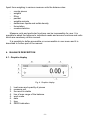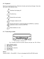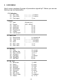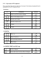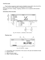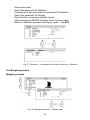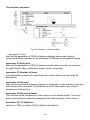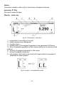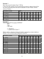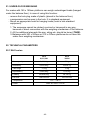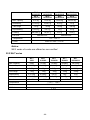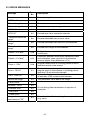
1
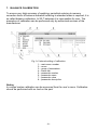
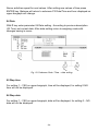
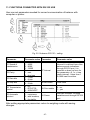
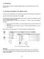
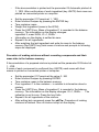
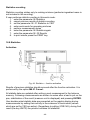
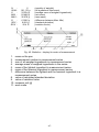
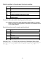
Manual number LTI-01-07/05/07/A Precision balances WLT balances WLX balances MANUFACTURER OF ELECTRONIC WEIGHING INSTRUMENTS RADWAG, 26 – 600 Radom, Bracka 28 Street POLAND phone +48 48 38 48 800, phone/fax. +48 48 385 00 10 Sales Department +48 48 366 80 06 www.radwag.com MAY 2007 -2- Table of contents 1. UNPACKING OF THE BALANCE...................................................................................5 1.1. WLX series .............................................................................................................5 1.2. WLT series .............................................................................................................6 2. GETTING STARTED ......................................................................................................7 2.1. Conditions of appropriate use.................................................................................7 2.2. Time of warming up................................................................................................7 2.3. Balance levelling ....................................................................................................7 3. INTENDED USE .............................................................................................................7 4. BALANCE DESCRIPTION..............................................................................................8 4.1. Graphic display.......................................................................................................8 4.2. Keyboard ................................................................................................................9 4.3. Connecting sockets ................................................................................................9 5. USER MENU ................................................................................................................10 5.1. Navigating within the menu ..................................................................................13 5.1.1. By means of balance keyboard................................................................... 13 5.1.2. By means of PC keyboard .......................................................................... 14 5.1.3. By means of virtual keyboard via RS 232 ................................................... 15 5.2. User’s menu .........................................................................................................15 5.3. Return to weighing ...............................................................................................16 6. WEIGHING ...................................................................................................................17 6.1. Tarring..................................................................................................................18 6.2. Manual inscribing of tare value.............................................................................18 6.3. Automatic tare ......................................................................................................19 6.4. Zeroing .................................................................................................................20 6.5. Functions of keys .................................................................................................20 7. BALANCE CALIBRATION ............................................................................................21 8. SETTING OF PRINTOUTS CONTENTS FOR GLP PROCEDURES ...........................22 9. TIME AND DATE SETTING..........................................................................................22 10. SETTING THE PARAMETERS ....................................................................................25 10.1. Filter setting..........................................................................................................25 10.2. Median filter setting ..............................................................................................25 10.3. Setting of autozero operating ...............................................................................25 10.4. Autozero setting ...................................................................................................26 10.5. Last digit ...............................................................................................................26 10.6. Negative ...............................................................................................................26 10.7. Automatic tare ......................................................................................................26 11. FUNCTIONS CONNECTED WITH RS 232 USE..........................................................27 12. PRINTOUTS .................................................................................................................28 13. SETTING ACCESSIBILITY OF WEIGHT UNITS..........................................................28 14. SETTING ACCESSIBILITY OF WORK MODES ..........................................................29 -3- 15. OTHER PARAMETERS................................................................................................29 16. USING WORK MODES ................................................................................................31 16.1. Counting pieces of the same mass ......................................................................31 16.1.1. Counting pieces after writing piece mass.................................................... 31 16.1.2. Counting through determine singular element mass................................... 32 16.1.3. Select an item from the database ............................................................... 34 16.2. Checkweighing .....................................................................................................35 16.3. Filling....................................................................................................................36 16.4. Percents ...............................................................................................................37 16.5. Weighing animals .................................................................................................39 16.6. Density of solids and liquids .................................................................................40 16.6.1. Density of liquids......................................................................................... 41 16.6.2. Density of solids.......................................................................................... 41 16.7. Formulation ..........................................................................................................41 16.8. Statistics ...............................................................................................................46 17. TYPES OF PRINTOUTS ..............................................................................................48 17.1. Standard printout..................................................................................................48 17.2. Non-standard printout...........................................................................................49 17.2.1. Inscribing texts ............................................................................................ 51 17.2.2. Select non-standard printouts ..................................................................... 54 18. ADDITIONAL ID’S ........................................................................................................55 19. COOPERATION WITH PRINTER OR COMPUTER.....................................................56 19.1. Connections .........................................................................................................56 20. TRANSMISSION POTOCOL ........................................................................................57 20.1. Some basic information........................................................................................57 20.2. Transmission parameters .....................................................................................57 20.3. Types of transmission ..........................................................................................58 20.4. Transmission characteristics ................................................................................58 20.4.1. Types of printouts ....................................................................................... 58 20.4.2. Continuous transmission............................................................................. 59 20.4.3. Continuous transmission „with pauses” ...................................................... 59 20.4.4. Stable result transmission ........................................................................... 60 20.4.5. Survey of automatic printouts...................................................................... 61 20.5. Command and response syntax...........................................................................61 20.5.1. Command syntax ........................................................................................ 61 20.5.2. Response syntax ........................................................................................ 62 20.6. List of commands computer - balance..................................................................63 21. UNDER-FLOOR WEIGHING ........................................................................................65 22. TECHNICAL PARAMETERS........................................................................................65 22.1. WLX series ...........................................................................................................65 22.2. WLT series ...........................................................................................................66 23. ERROR MESSAGES....................................................................................................67 -4- 1. UNPACKING OF THE BALANCE Cut open tape protecting the box. Take out the balance of factory package and place it on a stable base. Take out all components and assemble them according to below drawings. 1.1. WLX series Fig. 1a. Assembly of WLX…/A0 Scales Fig. 1b. Mounting of weighing pan in WLX…/A1 series Fig. 1c. Mounting of weighing pan in WLX…/A2, WLT…/X series - Remove transport protections Fig. 1d. Removing transport protections from WLX…/C1- C2 series -5- - Install the weighing pan according to the drawing below: Fig. 1e. Mounting of the weighing pan in scales WLX…/C1- C2 series 1.2. WLT series For 410 x 410mm balances, take the device out a package. Remove the protection items according to the drawing below. Screw in 4 levelling legs (next to protective shields in the bag) and set according to chapter 2 of this manual. Fig 1f. The balance with pan size 410 x 410mm Balances are supplied from 230 V AC / 11 V AC adapters. Connect to the power source and turn on the balance. -6- 2. GETTING STARTED 2.1. Conditions of appropriate use 9 9 9 9 9 9 9 place balance on a stable and flat table or free from vibrations balance should not be exposed to draughts and sudden air movements balance should be placed in room of stable temperature and humidity balance should be placed far from heat sources temperature of the room should be +15°C ÷ +30°C (for WLT balances) if static electricity influence balances, indications, its base should be earthed. Earthing clamp is in the back part of balance base balances should be levelled according to a level condition indicator to guarantee the appropriate weighing accuracy 2.2. Time of warming up To do the measurements correctly level the scale. Take the pan off carefully (without rapid pulls and hits) and turn the legs in order to level the balance, air bubble should be place in the centre of level condition indicator. Fig. 2. Balance levelling 1 - correct levelling 2 - incorrect levelling 2.3. Balance levelling Before performing measurements wait until balance reaches temperature stabilization. It is so-called warm-up time. It takes about 15 minutes. For weighing instruments that have been stored in low temperatures (e.g. during winter) the warm-up time is about 2 hours. 3. INTENDED USE The balances are used to do precise measurements in laboratories. It is possible to do the zero function in all measure range. The balance weights in following units: Fig. 3. Measure units -7- Apart from weighing in various measure units the balance also: − − − − − − − − counts pieces weights filling percent weights animals determines liquids and solids density formulation creates statistics Measure units and particular functions can be inaccessible for user. It is possible to adapt the balance to individual needs and access functions and units which are necessary at this moment. It is possible to define accessible or no-accessible in user menu and it is described in further part of the manual. 4. BALANCE DESCRIPTION 4.1. Graphic display Fig. 4. Graphic display 1. 2. 3. 4. 5. 6. 7. 8. load mass and quantity of pieces measure unit the result is stable line of max range of the balance work mode date time ZERO indication -8- 4.2. Keyboard Each key is dual-function key. Particular function can be done through. User also can move in the balance menu. Switches the display off. Function key. Selects the work mode Changes measure units Sends information to external instrument (PRINT) or confirms parameter value or function (ENTER). Sets indication to zero 4.3. Connecting sockets Fig. 5. Sockets of the WTX and WLT balances with pan size 165 x 165mm 1. 2. 3. 4. 5. 6. power adapter socket add display connector RS 232 port PS keyboard connector RS 485 port power supply Notice: Scales of WLX…/R and WLX…/K are not equipped with the RS 485 socket. -9- 5. USER MENU User’s menu comprises 9 groups of parameters signed by P. Below you can see listed groups and parameters. P1 Calibration 01 Ext. calibr 02 User calibr 03 Print report | * * * * * * * * | function | * * * * * * * * | function | * * * * * *0.1 | on P2 GLP 01 User 02 Project 03 Time print 04 Date print 05 User print 06 Project print 07 Id print 08 Last cal print | Nowak Jan | | AR – 65/04 | | * * * * * *0.0 | | * * * * * *0.0 | | * * * * * *0.0 | | * * * * * *0.0 | | * * * * * *0.0 | | * * * * * *0.0 | off off off off off off P3 Date/Time 01 Date format 02 Time format 03 Time 04 Date 05 Disp. Time 06 Disp. Date | * * * * * * * 0 | DA/MO/YR | * * * * * * * 0 | 24 hours | * * * * * * * * | Function | * * * * * * * * | Function | * * * * * * * 1 | on | * * * * * * * 1 | on P4 Readout 01 Filter 02 Median filter 03 Disp. refresh 04 Autozero 05 Last digit |*******3| |*******3| |*******1| |*******1| |*******1| 06 Negative 07 Aut. tare P5 RS - 232 01 Baud rate 02 Parity 03 Data bits 04 Stop bits 05 Handshake 06 Auto print 07 Interval 08 Min. mass 09 Print on stab 10 Pause | | normal normal 0.1 s on always 0 | no 0 | no |*******1| |*******0| |*******2| |*******1| |*******0| |*******0| |*******1| |*******4| |*******1| |*******0| - 10 - 4800 none 8 bits 1 bit none none * 0.1 s 10 d enabled * 0.1 s P6 Printout 01 Printout mem 02 Printout dest. 03 Printout No. 04 Pr. mem. No. 05 Pr. 1 start 06 Pr. 1 stop 07 Pr. 2 start 08 Pr. 2 stop ... . . . . . . . . . . 13 String 1 14 String 2 ... . . . . . . . . . . 92 String 80 |*******0| |*******0| |*******0| |*******0| |*******1| |*******1| |*******1| |*******1| |*******0| |*******1| |*******4| |*******1| |*******0| P7 Units 01 Grams 02 Kilograms 03 Pounds 04 Ounces 05 Ounces troy 06 Carats 07 Dwt 08 Taele Hk. 09 Taele S. 10 Taele T. 11 Momms 12 Grains 13 Newtons 14 Tical’ e 15 Custom 16 Custom factor | * * * * * * * 1 | enabled | * * * * * * * 1 | disabled | * * * * * * * 1 | disabled | * * * * * * * 0 | disabled | * * * * * * * 0 | disabled | * * * * * * * 0 | disabled | * * * * * * * 0 | disabled | * * * * * * * 0 | disabled | * * * * * * * 0 | disabled | * * * * * * * 0 | disabled | * * * * * * * 0 | disabled | * * * * * * * 0 | disabled | * * * * * * * 0 | disabled | * * * * * * * 0 | disabled | * * * * * * * 0 | disabled |*******1| P8 Work modes 01 Parts Counts 02 Checkweighing 03 Filling 04 Percent 05 Animal 06 Density 07 Formulation 08 SQC 09 Statistics |*******1 |*******1 |*******1 |*******1 |*******1 |*******1 |*******1 |*******1 |*******1 - 11 - function RS Standard Standard | enabled | enabled | enabled | enabled | enabled | enabled | enabled | enabled | enabled P9 Globals 01 ID setting 02 ID autoprint 03 Beep 04 Language 05 Backlight 06 Contrast 07 Screenserver 08 Balance ID 09 Software rev. 10 Par. Printout 11 Par .receive 12 Factory deff. 13 Password |******** |*******0 |*******1 |******** |*******1 |******** |*******0 | 164493 * * | MBT w.29 |******** |******** |******** | 0 | function | off | enabled | function | on | function | enabled | | | function | function | function | Parameters in user’s menu are: • functional – for particular activity e.g. the balance calibration • selectable – selects one of few values from the balance memory • noted – changes sets in the balance memory e.g. Date, time, user number, texts Menu – graphic version Press the F key to display main menu of the balance (display I). Select the submenu whose contents is displayed after pressing the F key (display II). Fig. 6. View of balance menu - 12 - 1 – number of main menu 2 – choice of function marker 3 – name of function 4 – name of currently performed activity 5 – number of submenu 6 – name of submenu 7 – attribute of submenu 8 – value referring to attribute 5.1. Navigating within the menu User moves in the menu by - the balance keyboard - PS keyboard, - Communicates from computer to the balance 5.1.1. By means of balance keyboard Exit to one step higher level to menu Entering parameter edition Moving cursor downwards Moving cursor upwards Confirmation of introduced values Cancellation of changes, menu exit - 13 - 5.1.2. By means of PC keyboard Every operation that can be made from the level of the balance keyboard Has its equivalent on the PC keyboard level: - functions PC Description Switch on/off the balance display Move to the balance menu Selects work mode Selects measure unit PRINT TARE - navigating Move up Move to level up Sets selected parameter Move down - for ENTER / PRINT and ESC keys Confirm changes Cancel and leave function without changes - 14 - balance 5.1.3. By means of virtual keyboard via RS 232 Most of the functions are done by the balance desk or PS keyboard. They are also done by sending orders computer – balance. This commands enables to move in the balance menu and control the balance work. Balance key #o #s #m #u #p #t PC level command 5.2. User’s menu Fig. 7. Main menu – submenu selection Press the F key. Selected menu appears on the display. Select what will be changed in this submenu (activate). Select through keys presented on the drawing above. Press the F key. - 15 - Reaction of the balance: - Activity of the balance (e.g. the balance calibration) is done from submenu described as Function - Attribute activation for submenu which is indicated (digit flashing means the value can be changed and some characters can be written) Fig. 8. The balance submenu 5.3. Return to weighing Introduced changes in settings will be saved after return to weighing mode with procedure of saving changes. Fig. 9. Return to weighing mode After introducing all changes in parameters settings press several times ESC key. When display indicates message, choose one of two options: ENTER – save changes ESC – without saving - 16 - 6. WEIGHING Following conditions must be fulfilled to get reliable results: - Stable temperature - Stable ground - Proper parameters for external conditions Before measurements load the pan and check if the balance show „precise in down left corner of the display (only if the zero” – displayed parameter P4 06 Autozero has the value 1: yes) and check if the is displayed in right up corner of the display. measurement is stable – If the balance does not show zero press the key If the conditions are unfavourable (no stable result) lines appear on the display. After settled time the balance returns to weighing mode without set up to zero. In this case wait until the conditions stabilize and press Esc again By the Units key select measure unit. Put the load on the pan and after stabilization read out the result. If measure unit user wants to use is not displayed during pressing the Units key check if it has access attribute. The indication can be set to zero many times. Sum of loads noted in the balance memory cannot be higher than max capacity. Between following measurements do not unplugged the balance. The balance should be switched off by the ON/OFF key. After pressing the key again the balance is ready to work without warm stabilization. - 17 - 6.1. Tarring For determining net mass place on the pan package of load and when indication is stable press T key. Fig. 10. Tarring – display view 1 –TARE signature (NET is being displayed) 2 –stable result signature Tarring can be performed repeatedly in the whole balance weighing range. Using tare function pay attention not to exceed the maximum weighing range. After removing the load and package display will indicate mass equal to mass of tare with minus sign. Notice: Tare value is not stored in balance memory and is deleted after disconnecting from mains 6.2. Manual inscribing of tare value Inscribing the tare value in weighing mode: ♦ Inscribe a tare value in a display format e.g. if a basic unit is „kg” with a division 0,005kg and you want to enter 1.05kg as a tare value , inscribe it as: 1.050 ♦ After pressing the first digit you can see an editing field in the last line. Fig. 11. Inscribing tare value – display view 1 –TARE value entered 2 –stable measurement pictogram 3 – inscribed tare value - 18 - ♦ ♦ ♦ Press T key You will see the tare value with “– “ sign on the display Tare value can be inscribed any time during weighing Notice Use “point” for decimal fractions. 6.3. Automatic tare This function is useful for quick determining net mass of weighed goods when tare values are different for each weighings. It is accessible in <P4 Readout> parameters group. Enabling function: Fig. 12. Automatic tare – enabling After setting an appropriate value of the parameter return to weighing 5.3. of this manual. The way of operation: • Press ZERO button when the pan is empty, • Put a package on the pan, • After stabilizing tarring is performed (Net designator is displayed in the top left corner of the display), • Put an article on the pan, • The display shows the net mass of the article, • Unload the pan, • Indication returns to zero, • Put the next package … and the cycle repeats. - 19 - 6.4. Zeroing key. Indication will return to For zeroing display indication press zero and display will indicate a graphic signature in left lower corner . Zeroing of indication is possible only in range of 2% of maximum capacity currently displayed balance/platform. If zeroed value is bigger than 2% of maximum capacity display will indicate error message and return to displaying previous value – for main balance or displayed mass will not change. Notice: Balance zeroing determines a new zero point treated by balance as precise zero. Zeroing is possible only in stable states of the indication. 6.5. Functions of keys Fig. 13. Key functions – graphic interpretation - 20 - 7. BALANCE CALIBRATION To ensure very high accuracy of weighing, periodical entering to memory correction factor of balance indication referring to standard mass is required; it is so called balance calibration. In WLT balances it is inaccessible for user. The procedure of calibration can be performed only by authorized services of the manufacturer. Fig. 14. Internal setting of calibration 1 – main menu number 2 – cursor 3 – group of parameters 4 – status bar 5 – parameter number 6 – parameter name 7 – parameter value 8 – parameter description Notice: In verified scales calibration can be accessed from the user’s menu. Calibration should be performed with no load on the pan! - 21 - 8. SETTING OF PRINTOUTS CONTENTS FOR GLP PROCEDURES P2 GLP his group of parameters allows to enable/disable printing some variables on the standard printout and calibration report. For variables: User and project name (max 8 alphanumerical characters) enter names with balance keyboard or with PS/2 keyboard. For remaining fields, select digits: 0 no (do not print during report) - 1 yes (print during report) Main view of GLP parameters can be seen in 7.2. chapter , fig. 14. If you use a PC keyboard read also chapter. 5.1.2. 9. TIME AND DATE SETTING Balances have a real time clock, which can be modified. Enter menu group P3 Date/Time according to the below scheme: Fig. 15. Date/Time submenu 01 Date format has doublestate choice according to below dependance - 1 date format Month/Day/Year - 0 date format Day/Month/Year After choice of appropriate value confirm with ENTER key. - 22 - 02 Time format has doublestate choice according to below dependance: - 1 time format 12 hours - 0 time format 24 hours After choice of appropriate value confirm with ENTER key. Format 12 hours. Is diffrentiated by placing letters PM or AM on printouts. 03 Time With F key enter parameter 03 Time setting according to below scheme. Fig. 16. Submenu Date / Time – time setting Set cursor next to value which os to be changed (Hour, Minute, Second). Confirm choice pressing F key. Using keys Pcs and n change values. Fig. 17. Submenu Date/Time – time setting – steering keys Confirm set value (last changed digit will stop pulsing) - 23 - Above activities repeat for next values. After setting new values of time press ENTER key. Balance will return to submenu P3 Date/Time and hour displayed on upper bargraph will change. 04 Date With F key enter parameter 04 Date setting.. According to previous description (03 Time) set current date. After date setting return to weighing mode with changes saving in menu. Fig. 18. Submenu Date / Time – date setting 05 Disp time For setting 1 – YES on upper bargraph, time will be displayed, for setting 0-NO time will not be displayed. 06 Disp date For setting 1 – YES on upper bargraph, date will be displayed, for setting 0 – NO date will not be displayed. - 24 - 10. SETTING THE PARAMETERS User by means of appropriate setting of parameters from menu group <P4 Readout> can adjust the balance to existing operating conditions (filter) and one’s expectations (refreshing, autozero, last digit displaying) Fig. 19. Submenu Readout – internal settings 10.1. Filter setting For perfect conditions filter can be set as very fast, however if conditions are bad (vibrations, draughts) filter should be set as slow or as very slow. Effectiveness of filter operating is different for weighing range. Filter works slower in time of “reaching” the final result, however stronger when mass gets to set range of filter operating (parameter range of filter operating available only in service menu – user do not have access to it). 10.2. Median filter setting Task of median filter is to eliminate single big disturbances. By setting digital value determines speed of filter operating. For zero option filter operating is off. 10.3. Setting of autozero operating To ensure accurate balance indications software “AUTOZERO” function was introduced. Task of this function is automatic control and correction of balance zero indication. - 25 - 10.4. Autozero setting If the function is active following results in declared periods of time are compared e.g. each 1s. If these results differs at less value than declared range AUTOZERA and e.g. 1 interval the balance sets to zero automatically and appears on the display. If the AUTOZERO function is active each measurement starts at precise zero every time. In special cases this function disturbs in the measurements e.g. when the load is put on the pan very slowly (pouring substance). In this case correcting system of zero indication can correct also indication of real load mass. AUTOZERA is switched on and off in the parameter P4 03 10.5. Last digit To ensure appropriate comfort of operating with balance user determines (depending on needs) if last digit of mass indication is to be displayed and in which states of balance. One of the below values can be set: - 0 never - 1 always - 2 when stab For verified balance option 1 – always is set (without possibility of changing) 10.6. Negative Possibility to change displaying mode – negative effect (dark background, light signs). 10.7. Automatic tare This function is useful for quick determining net mass of weighed goods when tare values are different for each weighings (see chapter 7.3. of this manual). - 26 - 11. FUNCTIONS CONNECTED WITH RS 232 USE User can set parameters needed for correct communication of balance with computer or printer. Fig. 20. Submenu RS 232 – setting Parameter 01 Speed of transmission 02 Parity 03 Date bits 04 Stop bits 05 Transmission control 06 Automatic printout Parameter value Parameter 0 : 2400; 1 : 4800; 2 : 9600; 3 : 19200 0 : no; 1 : see; 2 : dont see 1 : 7 bits; 2 : 8 bits 1 : 1 bit; 2 : 2 bits 0 : no; 1 : RTS/CTS; 2 : XON/XOFF 0 : no; 1 : constance; 2 : with breakes; 3 : for stable. Parameter value 07 Interval Interval it is defined how often balance sends indications through RS 232 port. It is counted on base on form for the parameter x 0.1 s = time yestu-interval). Value from 1 to 9999 can be written. 08 Min mass Give value 09 Print stable 0 : no; 1 : yes 10 Pause Intervals between following variables sent through RS 232 port After setting appropriate parameters return to weighing mode with saving changes. - 27 - 12. PRINTOUTS This function is used to configure standard and non-standard printouts. (see chapter 17). 13. SETTING ACCESSIBILITY OF WEIGHT UNITS In this group of parameters user declares measure units which are accessible for operators directly after pressing the key . All units which value of the parameters is set up at 1: yes are accessible from the level of toggling between units. For units described as 09 Taele Hk., 10 Taele S., 11 Taele T. there are following relations: • • If all of them have attribute 1: yes the balance show only first of them 09 Taele Hk If the measurement is done in units 11 Taele T set the attribute 0 : no for two previous Enter group of the parameters P7 Units according to the figure below. Fig. 21. Units of measure - setting NOTICE: For verified scales (DRH enabled) users can weigh in grams or in kilograms. Pressing the Units key do not effect changing the unit although they are set to YES in parameters. - 28 - 14. SETTING ACCESSIBILITY OF WORK MODES In P8 parameters group users can declare work modes that are accessible directly under the Mode key during operation. Fig. 22. Work modes - setting Every operation mode can be enabled/disabled separately. 15. OTHER PARAMETERS User can set parameters have influence on work with balance in group of the parameters P9 Others e.g. beep signals etc. Enter submenu group P9 Others the same as in chapter. 14. 01 ID Setting it includes 6 digits 6 codes which can be used during printouts for product specification, operator, batch etc. 02 ID autoprint for the option YES all digit codes are printed, for option NO the codes are not printed. 03 Beep beep signal for pressing keys - 29 - 04 Language selection of languages According to software versions (last letter in software version „e” or „w”) following languages are accessible: (e) language versions (w) language versions Polish English Czech German Dutch Russian Polish English Italian German Dutch French 05 Backlight switch on/off the backlight 06 Contrast changes contrast – after entering this function a window appears, by means of keys on the balance contrast on the display can be changed 07 Screen server if the screen server is switched on displayed values disappear after settled time and if displayed value of the measurement does not change. 08 Balance Id it is only information about factory number of the balance 09 Software rev. it is information about program number of the balance 10 Par. printout if the function is active the balance parameters in user menu are printed. User gives numbers of the parameters which should be printed. Fig. 23. Submenu others - printing settings - 30 - 11. Par. receive If the functions are activated all parameters of the balance are received through RS 232. After reception the balance informs user how many parameters are accepted, how many are changed, how many were declared incorrectly and how many were not accepted by the software. Printing and reception of the parameters is very easy and fast procedure of introducing new setting. After printing actual parameters to file in the computer user changes the parameters very fast and without any problems. User sends new corrected setting to the balance software. After these changes the balance accepts new set up. User must know all parameters and computer operation very well. 16. USING WORK MODES 16.1. Counting pieces of the same mass It can be done after write singular piece mass: - Write singular piece mass - Determine singular piece mass on base of standard quantity - Element selection from date base 16.1.1. Counting pieces after writing piece mass Start function of counting pieces. Fig. 24. Counting pieces – main menu - 31 - Set standard mass and press the ENTER or select 07 Start and press the F. Functions to count details are activated. Fig. 25. Counting pieces – display view APW WGH pcs – singular piece mass [g] – all pieces mass on the pan – mark for counting pieces Return to weighing - Press the MODE and display shows list of all functions - Select MO Weighing, Press the F, display show stage of weighing 16.1.2. Counting through determine singular element mass from the standard batch Start the procedure of counting pieces in accordance with p. 16.1.1, it does not matter which mass in the field 01. Select 07 Start and press the key F. In the counting pieces function press the key Units. Dialog window appears on the display. Select the batch quantity (fields 01 – 04) or write it in 05 – Standard. Fig. 26. Counting pieces with using standard batch - 32 - Then press the F key and follow orders presented on the display: Fig. 27. Display with APC function 1- single piece mass 2 - all elements mass 3 - APC (automatic correction of preciseness) function Display shows quantity of pieces which are on the pan (10 pieces). If less than currently counted quantity is added mass of a single piece is corrected. In this case APW = 5.2282 to 5.1837. From this moment following pieces are counted in relation to single mass. This way mass of singular piece can be determined on base of batch standard. The are four conditions of APC (Automatic Correction of Preciseness) in the balance software 1. quantity of pieces (after adding) must be higher than it was previously 2. quantity of pieces (after adding) must be less than twice quantity which was on the display before adding 3. actual quantity must be in tolerance ± 0,3 of the total value, 4. the result must be stable. If user decides that batch quantity is enough singular piece mass must be introduced into the balance memory after pressing the key F. - 33 - Fig. 28. Automatic Correction of Preciseness – record in date base Select the field and write names of weighed elements. Press the Enter (record name) and Enter (record value). Next to name singular piece mass should be introduced. It can be remembered using 02 Recall sample. 16.1.3. Select an item from the database Active function of counting pieces as it is shown on below scheme. Fig. 29. Browsing of the database of items Select piece form date base. Start counting pieces. - 34 - 16.2. Checkweighing The sample is weighed precisely when the limits of weighing are settled. The process is shown (side graphs) and controlled. The function activation: Fig. 30. Checkweighing – the function activation Display view Fig. 31. Checkweighing – display view 1 – result 2 – bargraph 3 – function name 4 – difference between mass of weighed load and middle of tolerance field (HI/LO) 5 – value of low (LO) and (HI) high limit 6 – graphs which presents weighing range - 35 - Remember to set the parameter 02 Higher threshold firstly. The balance program checks if the values are correct and if they are in measure range. If settled values of the parameters are incorrect the balance shows command about error and returns to setting parameters without changes. 16.3. Filling During dosage (pouring) load mass is filled up till the settled mass is reached. Before the procedure set the standard mass which is upper stage of the dosage. Activation of the function Fig. 32. Dosage – activation of the function Display view Fig. 33. Dosage – display view 1 – mass which should be added 2 – graphs 3 – function name 4 – TR reference value mass which has been declared 5 – WGH - mass on the pan - 36 - 16.4. Percents This function compares load mass to standard mass which value should be given. The result of this operation is displayed in percentages. Following functions: dosage, weighing, statistics can cooperate with deviation function. Activation of the function Fig. 34. Percents – activation of the function Display view Fig. 35. Percents – display 1 – percentage value, proportion of the mass on the pan and standard mass 2 – function name 3 – REF reference mass 4 – WGH - mass on the pan - 37 - Cooperation of the deviations with other functions During activation of the function set option YES for parameters M4 03, 04, 05. Select field START and start work. - after setting function Dosage YES give up and down stage as % values after setting function Dosage YES give the mass value in % after selecting Statistics select field Cancel and cancel previous statistics and change the attribute NO into attribute YES. Confirm this option and press the key Enter Fig. 36. Percents – cooperation with the functions 1 – percentage value relation of the load on the pan to reference mass 2 – stable measurement designator 3 – function name 4 – REF reference mass 5 – WGH mass on the pan 6 – graph which presents weighing range where the weighing range is 7 – statistics (N=0 – no measurements) 8 – active function dosage (load mass between 90 – 110%) After measurements e.g. 10 (quantity of measurements N=10) user can see results of statistics of made measurements. - 38 - − − − − − − − Enter work mode Select the parameter 05 Statistics Pressing the F key and enter the parameter 05 Statistics Select the parameter 02 Results Enter function of showing statistics results After pressing the ENTER statistics result can be printed Return to statistics submenu and higher levels – key ESC Fig. 37. Percents – cooperation with other functions – Statistics 16.5. Weighing animals Weighing animals Fig. 38. Weighing animals – display view - 39 - External setting - FILTR (Decides how fast final stable result is received, the faster filter the shorter time of measurement) - THRESHOLG (Value in actual scale intervals is value the result must be below The result of weighing must be smaller than value of actual scale intervals in order to do following automatic measurement) - AUTO START (Automatic start up following measurements) - STATISTICS (Statistics counting for particular subjects) - RUN (Start measurements) 16.6. Density of solids and liquids In additional equipment of analytical balances there are Specific Gravity Measurement Kit. Fig. 39. Specific Density Measurement Kit Components of the kit: 1 - Beaker stand 2 - Pan stand 3 – Float 4 – Beaker 5 - Thermometer clamp 6 – Thermometer 7 – String 8 - Float hook 9 - Top pan 10 – String 11 - Bottom pan 12 - Attachments - 40 - 16.6.1. Density of liquids Basic component during measure solids of liquids is glass float. It has precise determined capacity which is stamped on the float hook. Write password to balance memory before the measurements. During the measurement of liquid density mass of glass float in the air is compared to its mass in the liquid. The result is presented on the display automatically after its counting by the balance program. The result can be sent through RS 232 to printer or computer after pressing PRINT key. 16.6.2. Density of solids Density of solids can be determined in one of 3 different liquids: − − − WATER (distilled water), ALCOHOL (spirit 100% +/- 0.1% at 20 °C), OTHER (other liquid with known density) Measurement of density of solids is based on comparison sample mass in air (weighed on top pan) to the same sample mass in the liquid (on bottom pan). The programme counts density of sample and displays it on the display. The result can be sent through RS 232 to printer or computer after setting the key PRINT. Precise description of measurements performance and setting is the manual of Specific Gravity Measurement Kit. 16.7. Formulation This function is used to make mixtures according to recipes. This function is recommended to use for pharmacy. The balance memorises single ingredient mass and sum of weighed ingredients. Following data are presented on the display in this work mode: 1. load mass on the pan 2. present weighed ingredient name (max 10 characters) 3. mass which should be measured for actual weighed component „WGH” 4. quantity of ingredients that are weighed in the mixture „IC” 5. components mass already weighed „SUM” - 41 - The function activation Fig. 40. Recipes – internal setting parameter 01 Hints after set the parameter at YES the balance displays names and singular components mass recorded in the parameter 04 Recipe on the graphic display parameter 02 Auto print after set the parameter at YES the balance sends value on printer or computer through RS port after confirmation mass of each component parameter 03 Number of items user determines quantity of components the mixture should include (max 20 characters) parameter 04 Formula after set this parameter following submenu is displayed. In this submenu user can write names (not more than 10 characters) and set (standard mass) of each component in the mixture parameter 05 Formula printout This function prints composition of the mixture on connected printer. There are names and setting of particular component and total contents of the mixture. parameter 06 01 Statistics switch on (YES) or switch off (NO) statistic calculations - 42 - Notice: Calculation statistics refers only to total mass of prepared mixtures. parameter 07 Run Run work modes Recipes Display – main view Fig 41. Formulation – functions 1 – mass which is currently on the pan. 2 – stable measurement designator 3 – function name 4 – settled mass of the weighed ingredient in the parameter 04 Recipe 5 – Sum of weighed ingredients of the mixture which are in memory of the balance 6 – quantity of weighed ingredients in the recipe 7 – name of weighed component 8 – side graphs. Information how much left to gain settled component is presented on these graphs. Fig 42. graphs – automatically scaled - 43 - Procedure of preparing mixtures – according to recorded components and their mass in the balance memory Write names and components mass in the parameter 04 Recipe. Remember about the dependences: − there cannot be more than 10 signs − confirm each name by the ENTER key and write mass which will be in the mixture Fig. 43. Declared recipes − − − − − total mass of the mixture together with the container cannot be bigger than max capacity of the balance there cannot be more than 20 ingredients in the mixture Write quantity of ingredients in the parameter 03 Quantity of ingredients cannot be higher than 20 pcs The program records mixture contents in order they were introduced in the parameter 04 Recipes. If user enters 10 ingredients in the parameter 04 Recipes and set 8 for quantity of components the program finishes preparation of the mixture after weighing 8 components. The balance program creates mixture in order of recorded ingredients in the parameter 04 Recipes and starts from the ingredient 1 and finishes at settled ingredient in the parameter 03 Quantity of ingredients - 44 - − If the documentation is printed set the parameter 02 Automatic printout at 1 : YES. After confirmation of each ingredient (key UNITS) their mass are printed on connected printer or computer. • • • • • Set the parameter 01 Prompts at 1 : YES Enter function Recipes by pressing the ENTER key Tare container mass Weight first ingredient (mass in the WGH) Press the UNITS key. Mass of ingredient 1 is recorded in the balance memory. The information on the display changes: ingredient 2, mass WGH, IC=1, SUM=. . . . Information on the display is settled do zero. Repeat it for all ingredients After weighing the last ingredient and write its mass to the balance memory (the UNITS key) total mass of mixture and prompts to following steps are displayed. • • • Procedure of making mixtures without recording components and their mass date in the balance memory If documentation of a prepared mixture is printed set the parameter 02 Printout at 1 : YES. If mass of each component is confirmed (key UNIITS) each mass with their names is printed on connected printer or computer. • • • • • • • Set the parameter 01 Prompts at the value 0 : NO Enter function Recipes by pressing ENTER Tare container mass to the balance memory Pour ingredient 1 to the container – in relation to information about a mixture Press the UNITS key. Mass of ingredient 1 is recoded in the balance memory. The information on the display changes: IC=1, SUM=. . . The indication is set to zero. Press the key Units Repeat it for all ingredients of the mixture After writing last component press the →0/T←. Procedure of making mixtures is finished. Sum of mixture is kept on the display. - 45 - Statistics counting Statistics counting relates only to making mixtures (particular ingredient mass is not included in the counting). If user performs statistic counting in this work mode: 1. enter the parameter 06 Statistics 2. cancel previous results of statistic counting 3. set the parameter 06 01 Statistics to YES 4. enter work mode for preparing mixtures 5. perform measurement series 6. enter the parameter 06 Statistics again 7. enter the parameter 06 02 Results 8. to print results press the PRINT key 16.8. Statistics Activation Fig. 44. Statistics – function activation Results of previous statistics should removed after the function activation. It is performed by the option M8 01 Cancel. All statistic date are updated after writing a next measurement to the balance memory. Following measurements are written to series after a load is put on the pan, stabilization of the result (measure unit is displayed) and pressing ENTER. User decides what statistic data are presented on the graphic display during measurements by setting their activity in the submenu of work mode (values which are set for YES are active). Regardless to setting (YES/ NO), during final result (the key UNITS) the printout contains full statistics: - 46 - N : SUM : X : MIN : MAX : D : SDV : RDV : 5 161.121 g 32.224 g 20.486 g 35.578 g 15.092 g 6.581 g 20.4 % (quantity of weights) (all ingredients total mass) (average mass of weighed ingredients) (min mass) (max mass) (difference between Max- Min) (standard deviation) (variation factor) Fig. 45. Statistics – display for series of measurement 1. 2. 3. 4. 5. 6. 7. 8. 9. 10. 11. mass on the pan measurement number in measurement series sum of all weighed ingredients in measurement series average mass of weighed ingredients in the series mass of the lightest ingredient in measurement series mass of the heaviest ingredient in measurement series difference between the lightest and the heaviest ingredient in a measurement series value of calculated standard deviation value of variation factor measure unit [g] work mode - 47 - 17. TYPES OF PRINTOUTS 17.1. Standard printout The are 2 types of printouts. First is a standard printout. It comprises a result of weighing and all variables which have attribute YES in GLP submenu. In User and Project fields names should be written. Fig. 46. Declaration of variables to printout – submenu GLP Example of standard printout: Fig. 47a. Example of standard printout Fig. 47b. Example of standard printout Question mark before the load mass means that the result is not stable. - 48 - 17.2. Non-standard printout Procedure of creating non-standard printouts: − user can create 4 printouts, − give the number of the text which starts the printout e.g. Printout 1 Start – 1 and text number which finishes the printout e.g. Printout 1 Stop – 40. In this case texts from 1 to 40 are printed. − And then write text in the lines 1 ÷ 40. It is recommended to use PC keyboard what is simpler and faster way. − Non-standard printouts can overlap each other: Printout 1 Start – 1 Printout 1 Stop – 40 Printout 2 Start – 20 Printout 2 Stop – 40 Notice: During manual writing give all special characters as CRLF, tabulator etc. Fig. 48. Menu printouts – the function activation Non-standard printout can include: - Variable related to work mode and other necessities (mass, date, Project No, Constant texts inscribed in user menu Non-standard printout can include not more than 640 characters recorded as 80 texts 8 characters each (from the parameter Text 1 to Text 80). User can design 4 non-standard printouts - 49 - Non-standard printouts – internal setting − Printouts memory This function shows the level of memory filling, enables printing and cancelling printouts kept in the balance memory Fig. 49. Memory printouts – display view − Printout destination According to setting the printout can be sent to: • RS 232 port (immediate printout) • The balance memory (registration) • RS 232 port and the balance memory (immediate printout with registration) − Printout number This function selects number of non-standard printout which is printed after pressing PRINT button. User can choose: • Standard (result of weighing and declared changes in GLP menu are printed – option YES) • Printout No 1 • Printout No 2 • Printout No 3 • Printout No 4 - Memory number Indicate what type of printout is sent to the balance memory. It is possible to send non-standard printout from the texts to printer (computer) (text 1 – text 80), and the standard printout to the balance e.g.: Date, time, result of weighing. - 50 - 17.2.1. Inscribing texts Variables in all modes and with the same values %% %N %d %t %i %R %$ %P %U %F %C %K %I %1 %2 %3 %4 %5 %6 Printout of „%” single character Current net mass in basic unit Current date Current time The balance number The program number Pause The Project number The user number Current function name – work mode Date and time of last calibration Type of last calibration Deviation of last calibration Code 1 Code 2 Code 3 Code 4 Code 5 Code 6 Variables dependent on the active work mode Variable Description Mode where the variable is active %W mass of 1 piece COUNTING PIECES %H Top threshold %L Down threshold %Z Standard mass DOSAGE %B Reference mass DEVIATIONS %A Filter %b Stage %i Liquid %p Procedure %c Temperature %a Density of liquid %v Float volume WEIGHING WEIGHING ANIMALS MEASUREMENT OF DENSITY - 51 - Statistic variables in all modes apart from basic weighing %n %x %S %m %M %D %s %r The measurement number Average value Sum Min value Max value Difference between max and min value Standard deviation Variation factor Variable in all modes which value depends on the mode %V - Mass in current unit. Value connected to work mode e.g. counting pieces for mode Counting pieces or deviation from standard mass in % for mode Deviation Special characters used to create special printouts \\ \c \r \n \t \s \0 Single character „\” CR LF CR LF Tabulator skip to next „string” End of the printout Each text (Text 1 ÷ 89 Text 80) can include max 8 characters (letters, digits, special characters, spaces). To write a long sentence create it using 8 character texts. User can use special characters to include variables dependly on own necessities. - 52 - Example 1: Max mass cannot be higher than 11.250 g! If user write this sentence uses 46 characters grouped in adjacent lines of the text. Set up following texts and write 8 characters in each of them untill the sentence finishes. Parameter number 19 20 21 22 23 24 Text 10 Text 11 Text 12 Text 13 Text 14 Text 15 Text 1 M m n e a 2 2 a a o d l 5 3 x s t u 0 4 i s t e 5 m e h g 6 a c x e 1 ! 7 l a c 1 8 n e V . Example 2: Zaklad Mechaniki Precyzyjnej „RADWAG” Date: Time: Load mass: *****Signature:......... ***<present work mode>*** Należy wejść w ustawianie kolejnych tekstów i wpisywać po osiem znaków w każdym z nich aż zakończymy wpisywanie wydruku. Parameter number 25 26 27 28 29 30 31 32 33 34 35 36 37 38 39 Text 16 Text 17 Text 18 Text 19 Text 20 Text 21 Text 22 Text 23 Text 24 Text 25 Text 26 Text 27 Text 28 Text 29 Text 30 Text 1 Z e j D a T % a c g . c * 2 a c P n W t i t d * n . * - 53 - 3 k h r e A e m \ : * a . * 4 l a e j G : e r m % * t . * 5 a n c „ % : \ a N * u . % 6 d i y „ \ d 7 n s \ * r . F L s c S e . * k z R c \ 8 M i y A D c : o \ I : \ * Method of entering texts − from the balance desk Move up through digits, letters and sings by 1 Move down through digits, letters and sings by 1 Determine sign to change and move right (if the key is pressed flashing sign is moved in right direction. If no sign is written this keys makes space in the text) Determine sign to change and move lef (after this key is pressed flashing sign is cancelled) Confirm the text − from a PS/2 PC keyboard Press F2 to enter main menu. Press F3 to set parameters indications next to group P6 Printouts and press F2 to enter menu group and then select parameter. Press F2 to activate the procedure of writing the text. By means of keyboard write the text (max 8 signs) and confirm by Enter. Repeat this procedure for the rest of the texts. Description of the computer keyboard is in the. 5.1.2 of this manual 17.2.2. Select non-standard printouts If printout as STANDARD is chosen printout will only contain weighing result and variables declared in GLP menu. If one wants to print own non-standard printout, choose type of printout (1-4) give beginning and end of printout. - 54 - 18. ADDITIONAL ID’S 6 additional digital codes can be inscribed (6 digits each) They can be used while creating non-standard printouts (see 17.2.1.). Fig. 50. Additional codes – inscribing - 55 - 19. COOPERATION WITH PRINTER OR COMPUTER To send indication on the display with measure units to the computer or printer press the key < PRINT >. The speed of transmission 9600 bit/s is settled automatically. If external instrument has different baud rate change the baud rate in the balance menu. (see p. 11 of the manual). 19.1. Connections Fig. 51. Connections balance - computer Fig. 52. Connection cable scale – printer EPSON Fig. 53. Connection cable scale – printer KAFKA - 56 - 20. TRANSMISSION POTOCOL 20.1. Some basic information The communication protocol has been designed for exchanging information between RADWAG scales and external devices via RS-232C. The communication protocol has been designed in the form of request response messages. Scales always respond after receiving a command or automatically after completing a command. Using the set of commands you can fetch some information from scales or influence the operation of the device. E.g. It is possible to: • Identify the scale • Collect weighing results • Keyboard control • Display control • Changes of variables • Other External software have to assure not sending the next command without receiving the answer for the previous one. 20.2. Transmission parameters • • Scales are equipped in RS 232 (bidirectional) and RS485 (one direction from the scale to an external device). Possibile interface settings: Parameter Baud rate Parity Data bits Stop bits Flow control (cannot be used in HX) Setting 2400 – 4800 – 9600 – 19200 Even/odd/None 7/ 8 1/ 2 No – RTS/CTS – XON/XOFF - 57 - 20.3. Types of transmission Scales with MCB X.XX program use two different ways of transmission: • Continuous transmission or automatic printout (RS 232 and RS 485) • of request-response messages (request messages via RS 232 and response messages via RS 232 or RS 485) 20.4. Transmission characteristics 20.4.1. Types of printouts There are 3 types of automatic printouts in the scale provided it is not a retail scale and the DRH parameter in factory parameters is not enabled. Notice: If the parameter DRH is set to 1 this parameter is locked for edition, but it is possible to start continuous transmission by using a RS232 command. Settings/ RS-232/ Aut. Printout No 0 1 Name No Contin. 2 With int. 3 When stab. Description Request-response Continuous transmission Continuous transmission with the time pause between the subsequent printouts. The pause is set in the next parameter in the menu. Printouts are automatically generated after each stable measurement over min. mass (next parameter). The next printout can be generated when the result achieves the value below the Min. mass and again over it. - 58 - 20.4.2. Continuous transmission Results are transmitted in basic units. Transmission can be disabled/enabled using RS232 command: C1 CR LF – Switch on continuous transmission in basic unit C0 CR LF – Switch off continuous transmission in basic unit or using the parameter: settings/ RS-232/Aut. printout/continuous The frame length is constant (21 characters). Frame format: [SI] [space] [stability] [space] [sign] [mass] [space] [unit] [CR LF] Stability character – [space] if stable [?] if not stable [^] if an indication over the range [v] if an indication below the range sign – [space] for positive values or [-] for negative values mass – 9 characters justified to the right unit – 3 characters justified to the left 20.4.3. Continuous transmission „with pauses” Continuous transmission „with pauses” allows users to determine the time interval between the subsequent frames in the parameter interval. His type of printouts can be enabled only in parameters: Settings/RS-232/ Aut. printouts/with interv. The frame format is the same as in basic simple transmission. The interval is set in: Setting/RS-232/Interval - 59 - 20.4.4. Stable result transmission The scale automatically generates after each stable result separated by a stable result below the Min. mass that can be set in parameters. The intended use of this printout is for slip printers so it doesn’t have a starting characters and the length can vary from 18 to 20 characters. Standard length is 18 characters, but if the parameter digit marking has been enabled, the length increases to 20 characters, because additional brackets are printed e.g.: 383 kg 38[3] kg 3[83] kg It can be set in : Settings/Factory/digit marking Frame format: [space] [sign] [mass] [space] [unit] [CR LF] sign – [space] for positive values or [-] for negative values mass – 9 characters justified to the right unit – 3 characters justified to the left This type of printouts can be enabled in parameters: Settings/RS-232/Aut. print/when stab. Setting the Min. mass is possible in: Settings/RS-232/Min. mass Notice: The result is printed in current unit. - 60 - 20.4.5. Survey of automatic printouts No Name 0 No 1 Continuous 2 Wit interv. 3 When stab. Command Frame Quantity of characters [Command] [space] [stability] [space] [sign] [mass] [space] [unit] [CR LF] [SI] [space] [stability] [space] [sign] [mass] [space] [unit] [CR LF] [SI] [space] [stability] [space] [sign] [mass] [space] [unit] [CR LF] [space] [sign] [space] [mass] [space] [unit] [CR LF] 20-22 21 21 18 - 1-3 characters (repeated command characters) Stability character – [space] if stable [?] if not stable [^] if an indication over the range [v] if an indication below the range sign – [space] for positive values or [-] for negative values mass – 9 characters justified to the right unit – 3 characters justified to the left In any continuous transmission results are printed in basic units. In frames generated after pressing print key results are printed in current units. 20.5. Command and response syntax 20.5.1. Command syntax All commands are terminated with CR,LF (ASCII 13 dec,10 dec) Commands can include a parameter or not Overall format: ID CR LF – example of a command without a parameter ID _ PARAMETER CR LF – example of a command with a parameter where: • ID – command 1-4 characters • _ - space (ASCII 32 decimal) • • PARAMETER – string of ASCII characters. Texts have to be inscribed within a quotation marks. Spaces are not elements of the syntax – placed only for better readability. - 61 - 20.5.2. Response syntax Response can include parameters or not and additionally can signalise errors. After receiving an appropriate command scales response immediately with: Immediate response Acknowledge of receiving a command Accepting of a received command Not accepting of a received command Overall format: ID _ STATUS CR LF - example of a command without a parameter ID _ STATUS _ PARAMETER CR LF - example of a command with a parameter ES CR LF - error detected or not listed command where: • ID – command 1-4 characters • _ - space (ASCII 32 dec) • STATUS – one character that outlines the response status or a status of the scale. Different possibilities: A – in case of commands that cannot be completed immediately command accepted I – correct command but cannot be executed at that moment D – in case of commands that cannot be completed immediately command completed E – error of execution of a command e.g. incorrect parameter value. Additionally when the parameter is a weighings result, STATUS can be: _ - (space ASCII 32 dec) stable result ? – non-stable result ^ - error – result over the range v – error – result below the range - 62 - 20.6. List of commands computer - balance Function Command RESET INTERFACE R CR LF (zero actual orders, restore factory setting) Function Command SEND ALL COMMANDS FROM THE BALANCE PC CR LF (all recorded information in commands in the balance program are sent from the balance) Function Command SEND THE RESULT IN BASIC UNIT S CR LF (result is sent from the balance in basic interval after stability) Function Command SEND RESULT IN BASIC UNIT IMMEDIATELY SI CR LF Function Command SEND THE RESULT IN ACTUAL INTERVAL SU CR LF (result in current unit is sent from the balance after stability) Function Command SEND RESULT IN ACTUAL INTERVAL IMMEDIATELY SUI CR LF Function Command ZERO THE BALANCE Z CR LF (set the balance to zero after it reaches stability) Function Command ZERO IMMEDIATELY ZI CR LF Function Command TARE WHEN STABLE T CR LF Function Command TARE THE BALANCE IMMEDIATELY TI CR LF Function Command SWITCH CONSTANCE TRANSMISSION OFF IN BASIC INTERVAL C0 CR LF Function Command SWITCH CONSTANCE TRANSMISSION IN BASIC INTERVAL C1 CR LF Function Command SWITCH CONSTANCE TRANSMISSION OFF IN ACTUAL INTERVAL CU0 CR LF Function Command SWITCH CONSTANCE TRANSMISSION ON IN ACTUAL INTERVAL CU1 CR LF Function Command NUMBER OF THE BALANCE NB CR LF Function Command RANGE OF WEIGHIGN FS CR LF Function Command PROGRAM VERSION RV CR LF Function Command WRITE OR CHANGE DATE IN THE BALANCE PD CR LF (the balance sends settled date or the date is changed) - 63 - Function Command WRITE NEW OR CHANGE TIME IN THE BALANCE PT CR LF (the balance sends settled time or this time is changed) Function Command WRITE ACTUAL WORK MODE PM CR LF Function Command SEND SETUP PS CR LF (all balance setup is sent – printout of the parameters) Function Command SOUND SIGNAL – „BEEP“ B CR LF (sound beep is switched on) Function Command SEND LAST ERROR CODE ER CR LF (last order of the error is sent) Function Command ERASE HEADER CF CR LF (erases an inscription in „lower bargraph”) Function Command PERFORM INTERNAL CALIBRATION CL CR LF Function Command LOCK THE KEYPAD KL CR LF Function Command UNLOCK THE KEYPAD KU CR LF Function Command TURN OFF THE KEYPAD ECHO E0 CR LF (turns off sending the codes of pressed keys) Function Command TURN ON THE KEYPAD ECHO E1 CR LF Function Command TURN OFF THE SCALE O0 CR LF Function Command TURN ON THE SCALE O1 CR LF Function Command TURN OFF AUTOZERO A0 CR LF Function Command TUN ON AUTOZERO A1 CR LF Any command that is not listed but is terminated with <CR><LF> will cause the scale response ES<CR><LF>. - 64 - 21. UNDER-FLOOR WEIGHING For scales with 165 x 165mm platforms can weigh underslinged loads (hanged under the balance floor). In case of using this function: − remove the hole plug made of plastic (placed in the balance floor), − a suspension can be seen in the hole. It is standard equipment, − Mount an appropriate hook for hanging loads (hook is non-standard equipment). 1. The suspense cannot be rotated, revolved or tampered in any way, because of direct connection with the weighing mechanism of the balance. 2. All the additional elements like pan, string etc. should be tarred (TARE). 3. Balances with 300 x 300mm or 410 x 410mm platforms do not have the under-floor weighing mechanism. 22. TECHNICAL PARAMETERS 22.1. WLX series WLX 0,6/1,2/A1 Max. capacity WLX 3/6/A2 0,6/1,2 kg 3/6 kg Readability 0,01/0,02 g 0,05/0,1 g Tare range -1,2 kg -6 kg 0,02/0,04 g 0,1/0,2 g Repeatability Linearity ±0,02/0,04 g ±0,1/0,2 g Pan size 128×128 mm 165×165 mm Temperature Power +15° - +30° C 230V AC 50Hz / 11V AC - 65 - WLX 6/12/C1/R WLX 6/12/C1/K WLX 12/30/C1/R WLX 12/30/C1/K WLX 30/60/C2/R WLX 30/60/C2/K WLX 60/120/C2/R WLX 60/120/C2/K 6/12 kg 12/30 kg 30/60 kg 60/120 kg Readability 0,1/0,2 g 0,2/0,5 g 0,5/1 g 1/2 g Tare range -12 kg -30 kg -60 kg -120 kg Repeatability 0,2/0,4 g 0,4/1 g 1/2 g 2/4 g Linearity ±0,2/0,4 g ±0,4/1 g ±1/2 g ±2/4 g Max. capacity Pan size 290×360 mm Temperature 400×500 mm +15° - +30° C Power 230V AC 50Hz / 11V AC Notice: WLX series of scales are offered as non-verified. 22.2. WLT series WLT 3/6/X Max. capacity Readability WLT 6/12/X2 WLT 12/30/X2 WLT 30/60/X WLT 60/120/X3 3/6kg 6/12kg 12/30kg 30/60kg 60/120kg 0,05/0,1g 0,1/0,2g 0,2/0,5g 0,5/1g 1/2g Verification interval 0,5/1g 1/2g 2/5g 5/10g 10/20g Tare range - 6kg - 12kg - 30kg - 60kg -120kg Repeatability 0,1/ 0,2g 0,2/0,4g 0,4/1g 1/2g 2/4g Linearity ±0,1/ 0,2g ±0,2/0,4g ±0,4/1g ±1/2g ±2/4g Pan size 165x165mm 300 x 300mm o Temperature Power 410 x 410mm o + 15 C / +30 C 230V AC / 11V AC OIML class - 66 - 23. ERROR MESSAGES Message Error No Description "checksum error" 1.1 Errors during date transmission "A/D Error" 1.2 Converter error "Exceed range" 2.2 Exceed max measure range of the balance " Exceed range " 2.3 Exceed max measure range of the balance "A/D Null" 2.4 No divisions from the converter "A/D Full" 2.5 Exceed max value converter intervals 2.6 Exceed admissible tare or zero value 2.8 Exceed admissible tare value for the balances "Zero above the range" 2.9 Exceed zero range for the balances "Result > 4% Max" 2.10 "Result > 1% Max" 2.11 "Piece < 1 Div" 2.12 Piece < 10 Div" 3.1 "Ref < 1000 Div" 3.2 "above the range" 3.3 "Faulty value" 4.1 "Blocked - DRH" 4.2 "Overwite error" 4.3 " Party error" 4.4 " Frame error" 4.5 "stopped transmission CTS" 6.1 "Tara/Zero above the range" "Tara above the range " To high start mass (start the balance up with load on the pan) Difference between determined calibration mass and calibration mass recorded in the balance memory higher than (difference >1%) Singular mass value in counting pieces function less than actual scale interval Mass on the pan during determining mass of singular piece in the function of counting pieces less than 10 actual scale intervals Value of reference mass in the function deviations is less than 1000 current scale intervals The parameter value above the range Errors during date transmission to sprinter or computer Exceed admissible time during for an operation (e.g. zero) - 67 - MANUFACTURER OF ELECTRONIC WEIGHING INSTRUMENT RADWAG 26 – 600 Radom Bracka 28 Street Central tel. +48 48 38 48 800, tel./fax. + 48 48 385 00 10 Sales Department + 48 48 366 80 06 POLAND www.radwag.com - 68 -