1
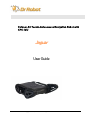
Outdoor All-Terrain Autonomous Navigation Robot with GPS-IMU Jaguar User Guide Copyright © 2010, Dr Robot Inc. All Rights Reserved. www.DrRobot.com Copyright Statement This manual or any portion of it may not be copied or duplicated without the expressed written consent of Dr Robot. All the software, firmware, hardware and product design accompanying with Dr Robot’s product are solely owned and copyrighted by Dr Robot. End users are authorized to use for personal research and educational use only. Duplication, distribution, reverse-engineering, or commercial application of the Dr Robot or licensed software and hardware without the expressed written consent of Dr Robot is explicitly forbidden. www.DrRobot.com Contact General: [email protected] Technical Support: [email protected] 25 Valleywood Drive, Unit 20 Markham, Ontario, L3R 5L9, Canada Tel: (905) 943-9572 Fax: (905) 943-9197 Copyright © 2010, Dr Robot Inc. All Rights Reserved. www.DrRobot.com Table of Contents I. II. III. IV. V. Specifications 4 Key Features 4 Jaguar Core Components 6 Upgrade Options 6 Knowing Your Robot 7 Overlook 7 Operation Scenario 8 Software Installation 8 Operation of Jaguar Robot 9 Using Dr Robot Jaguar Control Program 9 Recharging 13 Hardware and Electronics 14 Network Settings 14 Wireless Router Setting 14 Device Default Network Settings 14 Advanced Network Settings 14 Hardware Architecture 14 Motor Driver Board 16 Motion and Sensing Controller 16 Camera 16 GPS 16 9DOF IMU (Gyro, Accelerometer & Digital Compass) 17 Laser Scanner 17 Batteries 17 Charger 17 Motor with Encoder 18 Further Development & Programming 19 The Jaguar Control program 19 Motion Control/Sensing System: 20 Laser Scanner 22 GPS 22 9DOF IMU (Gyro/Accelerometer/Compass) 22 Camera with Two Way Audio 22 Advanced Development Copyright © 2010, Dr Robot Inc. All Rights Reserved. www.DrRobot.com -3- 23 I. Specifications Jaguar Mobile Robotic Platform is designed for indoor and outdoor operation. It comes with two articulated arms and is fully wirelessly (802.11G) connected. It integrates outdoor GPS, 6DOF IMU and digital compass for autonomous navigation. Jaguar platform is rugged, light weight (< 22Kg), compact, weather and water resistant. It is designed for extreme terrains and capable of climbing up stairs. The integrated high resolution video/audio and laser scanner provide remote operator detail information of the surrounding. Besides the ready to use control and navigation software, a full development kit including SDK, data protocol and sample codes, is also available. Key Features Rugged and reliable mobile platform for indoor and outdoor applications with excellent handling and mobility With two synchronized (or optional independently controlled) articulated arms Indoor and outdoor operation for extreme terrains Weather and water resistant enclosure Climbing up 45° slope or stairs (max 200mm or 8”) Light weight (<22Kg) and compact design with large payload capacity and robust maneuverability Autonomous navigation with outdoor GPS + 6DOF IMU and digital compass Managing max 200mm (8”) vertical step (obstacle) Rugged and reliable with shock absorbing suspension Integrated Laser scanner (Optional) Integrated high resolution video camera with audio All 802.11G (802.11N optional) wirelessly connected Head mounted display and joystick control providing outdoor operation with large and clear view even under direct sunlight Ready to use control and navigation software Full development kit including SDK, data protocol and sample codes, support Microsoft® Robotics Studio, Microsoft® Visual Studio, NI LabVIEW®, MATLAB®, Java® Terrain: Sand, rock, concrete, gravel, grass, soil and others wet and dry Slope: max 45° Maximum vertical step: 200mm (8”) Stair climbing: Max stair step height 200mm (8”) Traverse: > 260mm (10”) Two articulated arms (Standard: synchronized motion; Optional: independent controlled) Speed: 0 – 5.5Km/hr Turning radius: 0, min 850mm (33.5”) diameter of turning space Ground clearance: 38mm (1.5”) Operator remote control Autonomous navigation with GPS + IMU + Compass Indoor vision landmark GPS (Optional) Sealed weather resistant enclosure Temperature: -30° to +50° Shock resistant chassis Self-correction from flip-over with articulated arms Copyright © 2010, Dr Robot Inc. All Rights Reserved. www.DrRobot.com -4- Motion and sensing controller (PWM, Position and Speed Control) 5Hz GPS, 6DOF IMU and digital compass Laser scanner (4m or 30m) (Optional) Temperature sensing & Voltage monitoring Headlights Color Camera (640x480, 15fps) with audio WiFi802.11G (Optional WiFi 802.11N) Ethernet Serial (RS232) Long range antenna (Optional) Ethernet General purpose communication and power port Game Pad Controller Head mounted display (Dual 640 x 480), equivalent to 60” display viewed in 2.7m (9 feet) (optional) Portable computer (optional) Weight: 500g (without computer) Rechargeable battery: LiPo 22.2V 10AH Nominal operation time: 2 hours (Optional 4 hours) Track Motors (24V) (After gear down): 2 units Max output (x2): Max 80W, 100Kg.cm/track Rated current: 2.75A, Max current 16A Arm Motor (24V): 1 unit Max output: Max 80W, 450Kg.cm Rated current: 2.75A, Max current 16A Height: 176mm (7”) Width: 655mm (25.8”) Length 820mm (32.3”) (extended arms) / 640 mm (25.2”) (folded arms) Weight: 21.5 Kg (Standard Configuration) Carrying Payload: max 15Kg Dragging Payload: max 50Kg Full development kit including SDK, data protocol and sample codes, support Microsoft® Robotics Studio, Microsoft® Visual Studio, NI LabVIEW®, MATLAB®, Java® Copyright © 2010, Dr Robot Inc. All Rights Reserved. www.DrRobot.com -5- Jaguar Core Components JAGUAR-ME Jaguar Chassis (including motors and encoders) 1 PMS5005-J Motion and Sensing Controller (Jaguar Version) 1 WFS802G WiFi 802.11b/g Wireless Module 2 DMD2500 25A (peak 40A) Dual-channel DC Motor Driver Module 2 PMCHR12 DC-DC Power Board 1 AXCAM-A 640x480 Networked Color Camera (max. 30fps) with Two-Way Audio 1 OGPS501 Outdoor GPS Receiver with 5Hz Update Rate and WAAS 1 IMU9000 9 DOF IMU (Gyro/Accelerometer/Compass) 1 WRT802G 802.11b/g wireless AP/router 1 MCR3210 RS232 Interface Module 1 BPN-LP-10 22.2 V 10 AH Li-Polymer Battery Pack 1 LPBC5000 5A Li-Polymer Battery Charger 1 GPC0010 Game Pad Controller 1 Upgrade Options Laser Scanner (Range 4m) LAS04M Laser Scanner (Range 30m) LAS30M 22.2V 20 AH Li-Polymer Battery Pack BPN-LP-10 Head Mounted Display (800x600) HMD8H6H Host Controller PC HCPC1008 Please contact [email protected] for custom design and integration inquiry. Copyright © 2010, Dr Robot Inc. All Rights Reserved. www.DrRobot.com -6- II. Knowing Your Robot Overlook The figure below illustrates the key components that you will identify on the Jaguar robot. GPS+6DOF IMU+Digital Compass Drive-Track Recharging Socket Arm-Track Laser Scanner Camera Headlights Power Switch WiFi Antenna Handle Bar Jaguar Platform Copyright © 2010, Dr Robot Inc. All Rights Reserved. www.DrRobot.com -7- Operation Scenario Diagram below shows the typical operation scenario. The Jaguar is a wireless networked outdoor mobile robot. It comes with a wireless 802.11 AP/router. The remote host controller PC running the “Jaguar Control” program connects to the Jaguar robot via: Network cable – Connect the robot on-board AP/router. (DO NOT connect to the WAN port), or Wireless – To connect the host controller PC to the on-robot wireless AP/router, configure the host PC’s wireless settings using the default wireless configuration settings found in the Network Connection session of this manual. Human operator carrying the host controller PC could use the head-mounted display (accessory option) and the included game-pad controller in outdoor environment to monitor and control the operator under any outdoor lighting environment, even under direct sunshine. The included Jaguar control program will therefore be projected on the head-mounted display, where you could see all the sensor information from the robot, and the video streamed from the camera on robot (Please refer to “Jaguar control program” session for detail). Head-mounted display (Optional) Gamepad Controller Portable PC (Host controller PC) (Optional) Typical Operation Scenario Note: The host controller PC running the “Jaguar Control” program could be mounted on the robot instead off the robot if your application requires so. Software Installation Jaguar Control programs, application development library and supporting documents could be found from the Jaguar software CD. On the host controller computer, you should install the following programs from the installation CD: “Jaguar Control” program - installed by the Setup.exe from CD Google Earth program - could be downloaded from http://earth.google.com/downloadearth.html. Please follow its installation instruction. Copyright © 2010, Dr Robot Inc. All Rights Reserved. www.DrRobot.com -8- III. Operation of Jaguar Robot End user could develop his own Jaguar control program using the supplied development API and tools. Here, we are going to discuss how to control the robot using the included “Jaguar Control Program” (You need to install Google Earth program first). Using Dr Robot Jaguar Control Program This program will demonstrate how to control to navigate the Jaguar, move the arm-tracks and how to interpret, process, display and log multi-sensor information. This program provided with source code (c#) updates motor encoder reading, motor temperature, board voltage and battery voltage measuring at 10Hz; reads and displays IMU and Laser Range sensor data; displays GPS reading on the Google Earth; displays and controls Axis camera. Once you start the program, you will see the “Login Window” It will read all the configuration information from outdoorrobotconfig.xml in c:\DrRobotAppFile\. When “Connect Robot” is clicked, it will start the WiRobotGateway program (also in c:\DrRobotAppFile\) and try connecting to the Robot. Google Earth is then loaded and it may take a while. Google Earth supports offline use (without Internet), but you have to obtain the map online ahead of use. When Internet is not presented, this loading process will take a longer time for trying to connect with Google Earth website. You will not get the correct Latitude and Longitude position by mouse clicking on map before the map loading is finished. When loaded, click “OK” button. Copyright © 2010, Dr Robot Inc. All Rights Reserved. www.DrRobot.com -9- “FlyToSetPoint” button will bring you to the location (latitude/longitude) specified in outdoorrobotconfig.xml. This is the location you would like the map to center and show around. You should modify this location according to your location. This could be done by inputting the value in this xml file or navigating on Google Earth map to your interested point, then clicking “SaveSetPoint” button. The location value of the map center will then be saved to the outdoorrobotconfig.xml when program is closing. Copyright © 2010, Dr Robot Inc. All Rights Reserved. www.DrRobot.com - 10 - You could use the vertical track bar to zoom in or out. When the GPS-IMU module is presented, this program will connect and display the GPS information on Google Earth and IMU raw data on the 6 chart boxes. When camera is presented, the video and Av control buttons will be show in the video window. You could use the included Game pad controller to navigate the robot. When used outdoor, especially under direct sun lights, head-mounted display (optional accessory) will provide clear and large display for excellent outdoor experience. Set arm’s initial position Camera display to full size Flip Jaguar forward Move arm to initial “0 o” (flat) position Move arms to “30o” (Tilt-up) position Minimize camera display to original size Headlight On/OFF Flip Jaguar backward Left wheel track control Right wheel track control Front Arm UP from flat position Rear Arm Down toward flat position Gamepad Control Note: when using Gamepad control, you need to make sure the program window is in “focus”. Initializing or resetting arm-track position: After power up, or when the actual arm position is different from the diagram below, you should reset the arm-track position as following: drive the arm forward and being flat on the ground, we call this initial or “0” position (extend forward) Copyright © 2010, Dr Robot Inc. All Rights Reserved. www.DrRobot.com - 11 - then, click the “Set arm’s initial position” button to save this value and reset arm position display. Clicking button, you will display laser scanner data in polar view as shown below. Battery information and motor information will be displayed in window below: If the robot uses the included Li-Po battery, you need to stop the robot when voltage is below marked voltage (22.2V) to protect battery. Motor temperatures are also displayed in the display. PWM boxes show the PWM values received in motor driver board from motion control board. The two horizontal track bars show the gamepad left and right stick control value. You could record raw GPS-IMU/Encoder sensor data by clicking under current execution folder with file name GPSIMURec*.txt. button. The raw file will be saved All traces are displayed on Google Earth by KML data. Since the current version of Google Earth does not provide programming method to clear these KML data, there is risk of memory leak. You could manually clear these KML data by: right-clicking on “Temporary Places”, then choosing “Delete Contents”. (That is why we did not hide Google Earth program) On normal program exit, Google Earth will be closed. However, you should double check it using “Windows Task Manager”, or you may not be able to display Google Earth when you start Jaguar control program again. Copyright © 2010, Dr Robot Inc. All Rights Reserved. www.DrRobot.com - 12 - Recharging Jaguar robot uses high performance LiPo batteries. Extreme caution is needed when dealing with this type of battery, explosion and damage could occur. Please read the Charge Station manual first and follow all the safety rules before proceeding further. 1) Power on the Charge Station. Make sure "LiPo Charge" is displayed on the LCD screen. If not, use "Type/Stop" button to change it to "LiPo Battery". 2) Use "INC" button to choose how to charge battery. You can choose "LiPo Charge", "LiPo Balance" or "LiPo Fast Chg". We recommend using "LiPo Balance" charge to extend battery life and reduce risk. 3) You can use "Enter/Start" + "INC" + "DEC" buttons to change the charge current, DO NOT exceed the 5A charging current and do not modify the battery voltage. It should be "22.2V (6S)" for Jaguar robot. 4) Connect the charging cable to Jaguar charging socket; make sure it is fastened well. 5) Turn the Power switch (CCW) to charge position. 6) Keep pressing "Enter/Start" button for few seconds, the charge station will check the battery and display what the reading is. It should be same as your settings above. 7) If everything is right, you can press "Enter/Start" button again to start charging. Copyright © 2010, Dr Robot Inc. All Rights Reserved. www.DrRobot.com - 13 - IV. Hardware and Electronics Network Settings Wireless Router Setting The included pre-configured wireless 802.11 B/G router has the following pre-set settings: SSID DriJaguar Router LAN 192.168.0.245 WEP 128bits Login ID admin KEY 112233445566778899AABBCCDD Password drrobot Key Type Open Key Device Default Network Settings Note: The WiFi modules are configured for serial-to-Ethernet mode in Jaguar platform. WiFi Module 1 192.168.0.60 Port 1 Port Number 10001, UDP 115200. 8, N, 1, no flow control Port 2 Port Number 10002, TCP 115200. 8, N, 1, no flow control WiFi Module 2 192.168.0.61 Port 1 Port Number 10001, TCP 115200. 8, N, 1, no flow control Port 2 Port Number 10002, TCP 115200. 8, N, 1, no flow control Camera 192.168.0.65 User ID root Password drrobot Port 8081 Advanced Network Settings It’s possible to use different network settings (e.g. IP) for the server PC, but the “Virtual Server” settings on the router must also be changed accordingly in order for the Internet remote monitoring feature to work properly. You could also change the router settings such as IP and SSID etc,. If you need to do so, you are required to change the network settings on the WiFi modules on the robot by following the guidelines as illustrated on the WiFi Module manual. Please contact [email protected] if you need further support. Hardware Architecture The diagram below illustrates the inter-connection between the core electronic circuits and modules (some are optional accessories). Copyright © 2010, Dr Robot Inc. All Rights Reserved. www.DrRobot.com - 14 - Charging Plug Antenna Right Driving Motor Left Driving Motor Right Arm Motor Left Arm Motor LiPo 22.2V 10AH OFF ON Main Switch Motor Driver Board #1 Power 5V 3.3V Camera (AV) Power 5V Copyright © 2010, Dr Robot Inc. All Rights Reserved. www.DrRobot.com - 15 - Wireless AP/Router GPS Module Antenna Power 5V Power 5V LAN 5V WiFi Module 2 6DOF IMU WiFi Module 1 Head Lights Power 3.3V Port 10002 Port 10001 DC-DC Power Board 5V Power 5V Power 3.3V Port 10002 Port 10001 Communication Temperature Encoder-D Motion Sensing Controller (Jaguar Ver.) Laser Scanner 5V Host Control PC Gamepad Controller PWM-D PWM-C Encoder-C Encoder-B PWM-B PWM-A Power Control Port IN Power 5V Encoder-A Voltage Meter Head Light Control Motor Driver Board #2 Head Mount Display Motor Driver Board Two motor driver boards are used, one for the left and right track/wheel motors while the other one is for the arm-tack motors. Input power Max current Input voltage H-Bridge 2 channels up to 25A continuous power per channel, peak up to 50A per channel for a few seconds 6~24V, 30V absolute max Motion and Sensing Controller This is a special version of PMS5005 board. Input power 5V 6 PWM output Motor control mode Channel 0,1 for left and right arm-track Channel 3,4 for left and right track/wheel PWM control; Velocity control; Position control Sensor sampling 4 Channel encoder: Channel 0,1 for left and right arm-track Channel 3,4 for left and right track/wheel Board voltage measuring Battery voltage measuring 4 motor temperature measuring Other extended A/D channels (please contact Dr Robot). Camera Input power Lens Light sensitivity Resolutions Frame rate 5V 4.4 mm: 47° view*, F2.0, fixed iris, fixed focus 1-10000 lux, F2.0 0 lux with headlights LED on 640x480 to 160x120 H.264: 30 fps in all resolutions Motion JPEG: 30 fps in all resolutions PEG-4 Part 2: 30 fps in all resolutions Video compression H.264 (MPEG-4 Part 10/AVC), Motion JPEG MPEG-4 Part 2 (ISO/IEC 14496-2) Audio streaming Other features Two-way PIR motion sensor with configurable sensitivity. Max range: 6 m GPS Input power Update rate Sensitivity Accuracy 5V 5 Hz - 185dBW minimum Standard GPS service: WAAS service: Output Interface Position: <= 15m 95% typical Velocity: 0.1knot RMS steady state Position: <= 3m 95% typical NMEA 0183, default GPRMC/GPGGA/GPGSA/GPVTG Copyright © 2010, Dr Robot Inc. All Rights Reserved. www.DrRobot.com - 16 - Binary Output 9DOF IMU (Gyro, Accelerometer & Digital Compass) Input power Gyro Sensors 5V LY530ALH - 300º/s single-axis gyro LPR530ALH - 300º/s dual-axis gyro 3 Axis ADXL345 13bit resolution Max +/-16G 3 Axis HMC5843 magnetometer 50Hz Output all sensor raw data and processed data by on-board MCU through serial port Accelerometers Magnetic Compass Output Frequency Laser Scanner Two laser scanner options are available, one with measurement range of 0.02-4m, and other one is 0.1-30m. Input power Detectable range Accuracy Measurement Resolution Angular Resolution Scanning angle 5V 0.02-4m 0.02 to 1m: +/- 10mm 1 to 4m: 1% 1mm approx 0.36 degrees (360 degree/1024 partition) 240 degrees Input power Detectable range Accuracy Measurement Resolution Angular Resolution Scanning angle 12 V 0.1-30m 0.1 to 10m: +/- 30mm 1mm approx 0.25 degrees (360 degree/1440 steps) 270 degrees Batteries Battery type Voltage Capacity Discharge rate Max charge rate Cycle life Li-Po 22.2V (6 cells, 3.7V/cell) 10Ah Max 50A continuous, Max 100A peak 10A 500-1000 times Charger Charger type Maximum charge current Maximum discharge current Power Input Balance Charger 5A 5A 100-240V Copyright © 2010, Dr Robot Inc. All Rights Reserved. www.DrRobot.com - 17 - Motor with Encoder Jaguar (with arms) Track-arm motors Rated voltage Rated current Rated speed Rated torque Encoder resolution DC motors with steel gearbox 24V < 2.1A 63 RPM 20 Kg.cm x 2 1083 counts per revolution Track-wheel motors (2 units) Rated voltage Rated current Rated speed Rated torque Encoder resolution * DC motors with steel gearbox 24V 2.1A 122 RPM 16 Kg.cm 722 counts per (motor shaft) revolution * *After pulley-belt speed reduction (34:20), the controller read-in encoder resolution is: 722 x 34/20 = 1227.4 count per (wheel) revolution. Copyright © 2010, Dr Robot Inc. All Rights Reserved. www.DrRobot.com - 18 - V. Further Development & Programming The Jaguar Control program The Jaguar Control program is written with C# program with Visual Studio 2008 express under .Net 3.5 framework. You could download the development tools (Visual Studio 2008 express under .Net 3.5 framework) free from Microsoft. Please refer to the “Dr Robot Application Development Notes on C# Programming for Robot Control” for further information. The control program uses the supporting components and libraries that should have been installed when you install the control program from the installation CD: 1. DRROBOTSentinelCONTROL.OCX: Please refer to “WiRobot SDK API Reference Manual.pdf” for detail. 2. WiRobotGateway.exe 3. AXIS Media Control Library Set These are the camera control component for the AXIS Mini Camera (P/N: AXCAM) used for Jaguar robot. Please refer to “AXIS Media Control SDK Help” for detail. Copyright © 2010, Dr Robot Inc. All Rights Reserved. www.DrRobot.com - 19 - Motion Control/Sensing System: Jaguar comes with a special version of PMS5005 as its motion control and sensing board. It follows the Dr Robot WiRobotSDK protocol and user could control and access Jaguar by Dr Robot ActiveX control (DrRobotSentinelActivexControl.ocx) and WiRobot gateway program. Based on the protocol, you can develop your own program on any system. You could request protocol sample code from Dr Robot using C++/Java. You should contact Dr Robot with any questions regarding SDK API and protocol. The communication port is connected at WiFi module-I port 1. Gateway program will connect to this board at 192.168.0.60, port 10001. Here is C# sample code to control Jaguar System with ActiveX control, myJaguar is DrRobotSentinelActiveXControl. Arm Motor control: By default the system provides synchronized control, so the left/right arm motors only use channel 0 PWM signal, but you can get each encoder reading for left arm and right arm. private void myJaguar_MotorSensorEvent(object sender, EventArgs e) { //here reads back PWM value for all motors leftArmMotor.pwmOutput = myJaguar.GetMotorPWMValue1(); rightArmMotor.pwmOutput = myJaguar.GetMotorPWMValue1(); //right motor still uses PWM channel 0 leftWheelMotor.pwmOutput = myJaguar.GetMotorPWMValue4(); rightWheelMotor.pwmOutput = myJaguar.GetMotorPWMValue5(); leftArmMotor.encoderDir = myJaguar.GetEncoderDir1(); leftArmMotor.encoderPos = myJaguar.GetEncoderPulse1(); leftArmMotor.encodeSpeed = myJaguar.GetEncoderSpeed1(); rightArmMotor.encoderDir = myJaguar.GetEncoderDir2(); rightArmMotor.encoderPos = myJaguar.GetEncoderPulse2(); rightArmMotor.encodeSpeed = myJaguar.GetEncoderSpeed2(); } You can read board voltage(5V) and battery voltage in standard sensor Event. private void myJaguar_StandardSensorEvent(object sender, EventArgs e) { boardVol = ((double) myJaguar.GetSensorBatteryAD1() / 4095 * 9); motVol = ((double) myJaguar.GetSensorBatteryAD2() / 4095 * 33.749); } You can read motor temperature sensor in custom sensor event, function Trans2Temperature() is based on the sensor specification to translate AD value to temperature celcius degree. Also you can read left/right wheel motor encoder in this event. private void myJaguar_CustomSensorEvent(object sender, EventArgs e) { //here can read back left wheel motor and right wheel motor encoder information leftWheelMotor.encoderPos = myJaguar.GetEncoderPulse4(); leftWheelMotor.encodeSpeed = myJaguar.GetEncoderSpeed4(); Copyright © 2010, Dr Robot Inc. All Rights Reserved. www.DrRobot.com - 20 - leftWheelMotor.encoderDir = myJaguar.GetEncoderDir4(); rightWheelMotor.encoderPos = myJaguar.GetEncoderPulse5(); rightWheelMotor.encodeSpeed = myJaguar.GetEncoderSpeed5(); rightWheelMotor.encoderDir = myJaguar.GetEncoderDir5(); //temperature sensor here RightArmMotorTemp = Trans2Temperature((double)myJaguar.GetCustomAD7()); leftArmMotorTemp = Trans2Temperature((double)myJaguar.GetCustomAD5()); leftWheelTemp = Trans2Temperature((double)myJaguar.GetCustomAD6()); rightWheelTemp = Trans2Temperature((double)myJaguar.GetCustomAD8()); } NOCONTROL = -32768; To stop all motor, you could use: myJaguar.DcMotorPwmNonTimeCtrAll(16384, 16384, 16384, 16384, 16384, 16384); To control track/arm motor using PWM control with value 32767 (full PWM) you could use: myJaguar.DcMotorPwmNonTimeCtrAll(32767,NOCONTROL, NOCONTROL, NOCONTROL, NOCONTROL, NOCONTROL); or myJaguar.DcMotorPwmNonTimeCtr(0,32767); Using position control, move motor to encoder position 2000 in 2000 ms, you could use: myJaguar.DcMotorPositionTimeCtrAll(2000,NOCONTROl,NOCONTROL,NOCONTROL,N OCONTROL, NOCONTROL, 2000); or myJaguar.DcMotorPositionTimeCtr(0, 2000, 2000); Using velocity control, move motor at encoder speed 200, you could use: myJaguar.DcMotorVelocityNonTimeCtrAll(200,NOCONTROL,NOCONTROL,NOCONTROL ,NOCONTROL,NOCONTROL); or myJaguar.DcMotorVelocityNonTimeCtr(0,200); Same for the track/wheel motor control, the left track/wheel motor is at PWM channel 3, right track/wheel motor is at PWM channel 4. To control head lights, using expanded IO port bit7. Turn off light: Turn on light: myJaguar.SetCustomDOUT(expandedIO & 0x7f); myJaguar.SetCustomDOUT(expandedIO | 0x80); Software watchdog: The system will auto stop all the motors if it does not received any data package in 5 second. Copyright © 2010, Dr Robot Inc. All Rights Reserved. www.DrRobot.com - 21 - Laser Scanner Laser Ranger sensor (4m version, URG-04LX) is connected to WiFi module–1 port 2 after voltage level conversion. You could access the sensor data via TCP socket at port 10002 with IP 192.168.0.60. Default settings for the serial port are: 115200, 8, N, 1, no flow control, TCP, port number 10002 Date and communication protocol could be found in “URG-04LX commspec_eg.pdf”. GPS GPS sensor output interface is RS232 serial port, and connected to WiFi module-2 port 2 after voltage level conversion. You could access the sensor data via TCP socket at port 10002 with IP 192.168.0.61. Default settings for the serial port are: 115200, 8, N, 1, no flow control, TCP, port number 10002 NMEA 0183 sentence is described in file “GPS18x_TechnicalSpecifications.pdf”. GPS configuration tool is SNSRXCFG_200.exe 9DOF IMU (Gyro/Accelerometer/Compass) The output interface for this IMU sensor module is serial port. It is connected to WiFi module-2 port 2. You could read from this sensor via TCP port 10001 at IP 192.168.0.61. Serial Port Settings: 57600, 8, N, 1, no flow control, TCP, port number 10001. The sensor output rate is 50Hz (20ms) with output format of ASICII. It’s easier to read with a terminal program since the sensors’ measurements are reported in ASCII. DCM estimation and all measurements are delimited with “,”characters as well as a carriage return and line feed at the end of the data frame. Format: “ANG,roll,pitch,yaw,AN,gyroY,gyroZ,gyroX,accelX,accleY,accelZ,magnetomX, magnetomY, magnetomZ” After “ANG”, roll, pitch, yaw are estimated angle value by on board DCM algorithm. The unit is degree. After “AN”, the data are raw AD value for each sensor. Please note that the accelX, Y, Z value have been adjusted by subtracting the offsets by on board firmware. Sample data string: “ANG,0,0,10,AN, 379,378,379,1,-2, 243,4096,-1558,256” Camera with Two Way Audio You need to install the camera ActiveX control on your system by running the “AXISMediaControlSDK.exe”. You could find some sample codes (C++, C#, VB) in C:\Program Files\Axis Communications\AXIS Media Control SDK\samples and the corresponding SDK documents in C:\Program Files\Axis Communications\AXIS Media Control SDK\doc. By using the Microsoft’s “Windows Media Encoder 9” and Axis video capture driver, you could also access this camera in Intel’s OpenCV as same as accessing a USB camera. Copyright © 2010, Dr Robot Inc. All Rights Reserved. www.DrRobot.com - 22 - Advanced Development Please refer to document “GPS-IMU Sensor Module and Outdoor Autonomous Navigation Program” for detail on autonomous navigation programming using the Jaguar GPS and IMU system module. Support and sample codes are available for using OpenCV, LabVIEW and MATLAB. Please contact [email protected] for further information. Copyright © 2010, Dr Robot Inc. All Rights Reserved. www.DrRobot.com - 23 -