1
o_vne
1
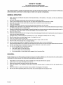
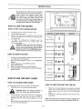
Model
No.
502.255193
, ,i i iil,ii
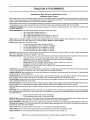
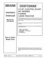
12 HP. LECTRIC START
40" MOWER
SPEED
LAWN TRACTOR
CAUTION:
Read And Follow
All Safety Rules
And Instructions
Operating
This
Equipment.
Before
® Assembly
o Operation
e Maintenance
e Service
® Repair
F-91726
12-01-90
and Adjustment
Parts
Sears, Roebuck and Co, Chicago, IL 60684
UoS.A.
Printed
inUSA
SAFETY
Safe Operation
As Recommended
RULES
Practices
by American
for Riding
National
Vehicles
Standards
Institute
This cutting machine is capable of amputating
hands and feet and throwing objects. Failure to observe
safety instructions
could result in serious injury or death to the operator or bystanders.
GENERAL
1o
the following
OPERATION:
Read, understand,
and follow
all instructions
in the instruction
Book, on the machine,
on the engine,
and with any attachments
before starting_
2
Only aliow responsible
adults familiar
3..
Clear the area of objects
4o
Be sure the area is clear of other people
5.
Never carry passengers.
6.
Disengage
all attachment
7,_
Disengage
power
8.
such as rocks, toys, wire,
ctutches
to the mower
look down and behind
before
the mower
not operate
the mower
without
9.
Slow
before
100
Never leave a machine
remove
unattended
Disengage
12.
Stop the engine before
13.
Mow
14.
Do not operate
15,.
Watch
Use extra
Always
from
/
18,
power
to start the engine_
up. Do not mow
in reverse
untess absolutely
necessary.
Always
at anyone
or at places where people may bee Do
backing.
the entire grass bagger
orgood
when
caution
the unit, Aiways
artificial
loading
glasses
wear
puliing
loads
ao
Use oniy approved
transporting
the grass bagger
while
operating
when
wear safety
when
removing
the machine
Use care when
before attempting
before backing
from the mower
or the mower
with the engine running, Always
to attachment(s)
only in daylight
17,.
if anyone enters the area°
guard
in place,
disengage
the blade(s),
set the parking
brake, stop the engine and
dismounting
1 1,
16.
by the b|adav
Stop the machine
discharge_ Do not point discharge
either
the machine.
turning.
the key before
for traffic
and shift into Neutral
and while
to operate
etc_ which could be picked up and thrown
before mowing.
or any attachments
Be aware of the directlon
down
with the instructions
or not {n use,, Disengage
or unclogging
the influence
near or crossing
not mowing°
or unloading
of alcohol
or drugs
the machine
when
using
a trailer
you operate
eye protection
you make an adjustment
when
or using heavy
or when
very tired,,
roadways,
or an eye shield when
hitch
when
light,
under
drawbar
the blade(s)
the chute.
or truck
for transporting.
the unit to protect your eyes from foreign
or repair
objects
that can be thrown
to the machine,
equipment°
points.
b.,
Limit loads
c.
Do not turn sharply,.
to those you can safely
Use care when
d.
Use counterweights
or wheel
control
backing.
weights
when
suggested
in the Instruction
Book.
CHILDREN:
Tragic accidents can occur if the operator is not alert to the presence of children, Children are often attracted to the machine and the
mowing activity. Never assume that children will remain where you last saw them,
1.
Keep children
2,
Be alert
out of the mowing
and turn the engine
3
Before
4.
Never carry
machine,
children
or any passengers
5,
Never
children
to operate
6
Use extra care when
F-91726
and when
allow
backing,
area and in the watchful
off if children
look behind
approaching
enter
and down
They
the machine_
blind
care of an adult
for small children,
may fall off and
Instruct
corners,
other than the operator.
the area.
shrubs,
chitdren
be seriously
in the dangers
trees or other
2
objects
injured
or interfere
with
of the machine
that
may obscure
vision.
the safe operation
of the
SAFETY
RULES - continued
SLOPE OPERATION:
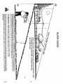
Slopes and rough terrain are major factors related to loss of control and tip over accidents which can result in severe injury or death.
All slopes require extra caution. If you cannot back up the slope or if you feet uneasy on the slope, do not mow ito See the "Slope
Guide" in the back of this book to check for safe operation,
DO
1.
Mow
up and down
2o
Remove
slopes, not across.
3
Watch
4.
Use slow
5,,
Follow
6.
Use extra
7.
Keep all movement
8
Avoid
1o
Do not turn on slopes
Z,
Do not mow
obstacles
such
for holes,
as rocks,
speed,
Choose
care with
etCo..
Uneven
a low enough
the manufacturer's
starting
limbs,
ruts or bumps°
terrain
recommendations
grass baggers
or other
on the slopes
slow
or stopping
on a slope.
could
overturn
gear so that you will
for wheel
weights
attachments,
and gradual.,
the machine.,
or counterweights
they can change
Do not make sudden
If tires lose traction,
Tall grass can hide obstacles
not have to stop or shift
disengage
while
on the slope°
to improve
the stability
changes
the blades
stability.
of the machine.
in speed or direction
and proceed
slowly
straight
down
the slope,
DO NOT
injury
unless
near drop-offs,
absolutely
ditches
necessary,
then only turn slowly
or embankments.
and gradually
downhill,
A wheel over the edge or an edge caving
if possible,
in could cause a sudden
overturn
and an
or death.
3.
Do not mow
4.
Do not try to stabilize
on wet
grass.
5,
Do not use a grass bagger
Reduced
the machine
traction
could
by putting
or other
cause sliding.
your foot
rear mounted
on the ground.
accessories
on steep
slopes
(greater
than
10 °}
SERVICE:
1,
Use extra care when
a
Use only
b
Never remove
handling
an approved
gasoline
and other fuels,
Fuels are flammable
and the vapors
are explosive,
container,,
the gas cap or add fuel with the engine
running,
Allow
the engine to cool for several
minutes
before
refueling
Do
not smoke.
c,
Never
refuel
the machine
d°
Never
store
the
indoors
machine
with
fuel in the
tank or fuel
container
inside
where
there
is an open
flame,
such
as a water
heater,
2.
Never
3o
Keep all nuts and bolts,
start
and nicks
or run the engine
4,
Never tamper
5.
To reduce
years.
with
Stop
Never make adjustments
and inspect
Mower
blade(s)
housing
area.
Check
Wait
in good
Check their
replaced
a factory
for wear or damage
reptacement
such as cracks
blade. For safety,
replace
the
condition
proper
operation
regularly,
settings
parts
the brake
when
are sharp
operation
for all movement
or overspeed
are subject
always
an object,
Repair,
if necessary,
with the engine running,, The carburetor
Clean uP oil or fuel sPilfage
Allow
the machine
to
make
before
re-starting
can be adjusted
with the engine
running,
Do not change
the engine,.
to wear, damage
sure the grass
and deterioration,
bag is empty
which
Frequently
could
check
expose
moving
components
parts or allow
and replace
with
objects
to be
manufacturer's
necessary
and can cut
frequently,
to stop before
Wrap
the blade(s)
or wear
Adjust
and service
as required,
servicing
gloves
and use extra
caution
when
any part of the uniL
Look for this symbol
precautions,.
Become
F-91726
check the blade(s)
with
free of grass, leaves or other debris build-up
if you strike
or repairs
components
For storage,
recommended
11
the equipment
governor
Grass bagger
10,
nuts tight. Frequently
storing
7.
9,
devices.
keep the machine
6,
the engine
area
must be immediately
Keep the equipment
the safety
fire hazards
cool before
thrown,
an enclosed
the blade attachment
A blade that is bent or damaged
blade every two
8
inside
especially
This
Alert!
3
to indicate
symbol
Your
Safety
important
indicates:
safety
"Attention!
Is At Risks _
servicing
them
or the blade
Congratulations
on your
purchase
of a Sears Tractor.
designed, engineered and manufactured
ible dependability
and performance.
to give you the best poss-
If you experience
any problem
you cannot
see your nearest
Sears Service
Department.
well trained
this unit.
technicians
and the proper
Please read and retain this manual.
to assemble and maintain
"Safety
Rules".
CUSTOMER
easily
remedy,
tools
to service
please
or repair
The instructions will enable you
Always
observe
the
RESPONSIBILITIES
Carefully
the unit
•
Follow all the assembly
unit.
=
Know
how to operate
the
unit°
operate
all standard
Make
sure
that
Correctly
adjust
and accessory
the
operator
the
correctly
the unit.
Operate the unit only with guards, shields, and other safety
items in place and working correctly..
t
Complete
with
all maintenance
authorized
on the unit. Service
or approved
This unit is equipped
replacement
with
an internal
brush-covered
is equipped
or state
laws
maintained
in the
4442
or grass-covered
State
with
(if any).. If a spark
in effective
of California
of the California
have similar
Authorized
working
laws_ Federal
Service
Center
MAINTENANCE
A Sears Maintenance
nearest Sears Store
be
laws
apply
on federal
(Section
states
Model
may
lands., See an
Serial
for the muffler.
AGREEMENT
to the back of the frame
Number:
502.255193
Number:
on this unit
See the
Keep these numbers
for future
i,,111, ,, i,
reference.
ii
TWO YEAR WARRANTY
START
RIDING
EQUIPMENT
AND GRASS BAGGER ATrACHMENT
the date of purchase,
when this
riding equipment
and grass bagger
excludes
blade(s),
and the date
Date of Purchase:
Agreement
is available
for information..
blade adapter(s),
instructions
equipment
attachment
are maintained,
lubricated,
and
in the Owner's Manual, Sears will repair free of charge any defect in
and grass bagger attachment°
spark plug(s), air cleaner, and belt(s), which are expendable
arrd become
worn during
does not cover:
- tire replacement
or repair
caused
by punctures
from outside
- repairs necessary because of operator' abuse or negligence,
instructions
contained
in the Owner's Manual; and
- riding
TRACTOR
the serial number
The model number and serial number are found on a decal
attached
by law
tuned up according to the operating and maintenance
material or workmanship
in this electric start riding
This warranty
Record in the space below
of purchase of this unit.
loca|
it must
LIMITED
This warranty
normal use.
LAWN
exhaust
applicable
Code). Other
for a spark attester
..........................
forest-covered,
is used,
is required
Resources
ON ELECTRIC
For two years from
iiiiii
engine
order by the operator:
the above
Public
meeting
arrester
30 foot pounds
4 bushels
parts.
land unless the englne's
a spark arrester
Blade Nut Torque
Grass Bagger Size
the unit only
combustion
and must not be used on or near any unimproved
system
Tilt Seat
The seat tilts forward for easy access to the battery.
Mower Housing
The full=floating suspension and twin blades
give an even cut,,The lift lever has six height positions from 2 to
4 inches,
equipment
can
=
NOTE:
Tire Air Pressure
Front and Rear 12 psi
All Gear Transaxle
Six forward speeds and one reverse.,
Ground Speed
Forward 0-5,4 MPH.
Reverse 0-1 _6 MPH.
read and foilow the rules for safe operation.. Inspect
instructions_
SPECIFICATIONS
Briggs & Stratton Engine
12 HP,.
Charging System
3 amperes at 3600 rpmr.
Fuel Tank Size
1 gaIIon
Type Of Fuel
Unleaded Regular
Oil Capacity
3 pints
Oil Type
Above 32 °
SAE 30 or 10W30
Below 32 °
SAE 5W30
Spark Plug (Gap 0,.030")
Champion J 19LM
Sears 71-33312
STD361458
We have competent,
your unit properly.
o
on
PRODUCT
It has been
equipment
and grass bagger
attachment
FULL 90-DAY
objects
including
used for commercial
WARRANTY
(such as nails, thorns,
the failure
or rental
to maintain
stumps,
or glass);
the equipment
and
according
to
purposesv
ON BATTERY
For 90 days from the date of purchase, if any battery included with this riding equipment
proves defective in material
and our testing determines
the battery will not hold a charge, Sears will replace the battery at no charge.
or workmanship
WARRANTY SERVICE IS AVAILABLE BY CONTACTING THE NEAREST SEARS SERVICE CENTER/DEPARTMENT tN THE UNITED
STATES, This warranty applies only while this product is in use in the United States_
This warranty
gives you specific
legal
Sears. Roebuck and Coo, D/731CR-W,
F-91726
rights, and you may also have other rights
Sears Tower, Chicago, IL
60684
4
which
vary from state to state.
i
i
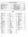
TABLE
OF CONTENTS
SAFETY RULES ...............................................
2-3
CUSTOMER RESPONSIBILITIES
.........................
4
PRODUCT SPECIFICATIONS
...............................
4
WARRANTY
......................................................
4
TABLE OF CONTENTS
.......................................
5
INDEX ...............................................................
5
TRACTOR ATTACHMENTS
................................
6
ASSEMBLY
..................................................
7-20
OPERATION
...............................................
21-26
MAINTENANCE
..........................................
SERVICE AND ADJUSTMENT
......................
STORAGE ........................................................
TROUBLE SHOOTING CHART ..........................
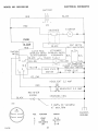
ELECTRICAL SCHEMATIC
................................
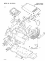
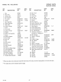
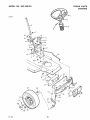
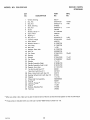
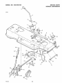
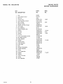
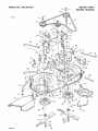
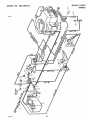
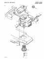
REPAIR PARTS, MOWER ............................
REPAIR PARTS, GRASS BAGGER ...............
27-34
35-41
41
42
43
44-57
58-59
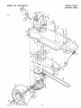
REPAIR PARTS, TRANSAXLE
.....................
REPAIR PARTS, ENGINE .............................
60-61
62-66
PARTS ORDERING/SERVICE
................
Back Page
iNDEX
F
A
......................................................................
P
Parking Brake
21, 22
Parts Bag, Grass Bagger ...........................
11 - 12
Parts Bag, Lawn Tractor .........................................
7
............................
........................
R
........................................................
....
...........................................................
Filter Air .................................................................
34
Adjustments:
Filter Fuel
34
Blade Engagement Control 29 .....................
Fuel
25
Brake, Drive
30
Carburetor ....................................................................
35
Fuel System Storage ...............................................
41
Fuse ..........................................................
4t, 43, 54
Clutch .........................................................................
30
G
Mower Housing Level ......................................
38
Throttle Control Cable ................................ 35
Grass Bagger:
Assembly ............................................................
13 20
Assembly
7 - 20
Operation ..................................................................
24
Attachments ...................................................................
6
B
Service and Adjustment ................................
40
Replace Motion Drive Belt
38
Replace Mower Drive Belt .................................
37
..............................
S
Safety Rules .......................................................
2 -3
Seat, Install ...............................................................
9
Service and Adjustments .........................35 - 40
I
Battery, Emergency Start ...............................
40
Bagging Tips ...................................................................
26
Carburetor ........................................................
35
Ignition Switch .........................................................
21
Battery:
L
Fuel Filter
34
Charge ..............................................................................
8
Fuse ....................................................................
41
Lift Lever
21 23
Clean and Check .............................................
32
Level Mower Housing .......................................
38
Lights
21 40
Emergency Start
41
Lubrication ...................................................................
27
Light Bulb, Replace
40
Install .......................................................................
20
Motion Drive Belt ................................................
38
M
Storage ............................................................................
41
Mower Ddve Belt ..................................................
37
Maintenance .....................................................
27 34
Belt:
Air Filter
34
Mower Housing, Install ......................................
36
Motion Drive, Adjust
30
Mower Housing, Remove ............................36
Battery .................................................................
32
Motion Drive, Replace
38
Blade ...........................................................................
28
Sharpen Blade ..............................................................
28
Mower Drive, Adjust ......................................
29
Shift Lever ................................................
21, 22 31
Blade Engagement Control .............................
29
Mower Drive, Replace ...........................
37
Brake
30
Shift Gate, Adjust ..............................................31
Rooting, Check ................................................
10
Clutch ......................................................................
30
Slope Guide
67
Blade, Remove and Install .......................................
28
Spark Arrestor .............................................. 4 34
Engine 011
33
Blade, Sharpen ........................................................
28
Lubrication .........................................................
27
Spark Plug ...........................................................................
34
Blade Engagement Control:
Specifications, Product ............................................
4
Muffler, Check
34
Adjust
29
Speed Control Chart .............................................
22
Spark Arrestor ...........................................4 34
Operatlon
23
Spark Plug
34
Start Engine .....................................................................
25
Brake, Check and Adjust Drive .............................
30
Tires
32
Steering Whee! ..........................................................
9
Brake Pedal, Operation .................................. 21
C
Maintenance Schedule ................................... 27
Stop Unit ..................................................................
22
Storage
41
Mower Housing
Carburetor Adjust .................................................
35
T
Clean ......................................................................
40
Charge Battery ................................................................
8
Throttle Control .....................................................
23
Level Adjustment ...............................................
39
Clutch/Brake Pedal ............................................21
Throttle Control Cable Adjust ..........................
35
Remove and Install .........................................
36
Controls .........................................................................
21
Tire Pressure
10, 32
Cutting Height ......................................................23
Mowing and Bagging _t_ps ...............................26
E
Trouble Shooting Chart ......................................
42
W
Oih
Electrical Schematic
43
Check ..............................................................33
Warranty ........................................................
4
Engine:
Wheel Align Front ....................................... 41
Carburetor .....................................................35
Change ...................................................
33
Wiring Schematic .......................................... 43
Operating Tips ................................................... 26
Oil, Change ................................................ 33
Operation ............................................................
21 - 26
Oil Level, Check
33
Grass Bagger .................................................24
Oil Type ...............................................................
33
LiftLever .......................................
21, 23
Operation Speed Chart .................................
22
Mower Housing ............................................23
Starting ....................................................... 25
Operation On Hills ...................................... 23
Stopping ................................................... 22
Parking Brake .................................... 2I, 22
Storage ...........................................................41
Shift Lever .............................
21 22
Throttle Control ..........................
21, 35
Start Engine ...................................
25
Trouble Shooting Chart ..................
42
Stop The Unit .....................................
22
....
......................................................................
.....................................
........................................................
............................
.........................................
............................................
......................................................................
.......................................................
..........................................
..........................................
.........
.......................................................................
...................................................
..............................................................
.......
................................................
....................................................................
................................................................
............................................................
..........................................................................
................................
....................................
....................................
........................................
.....................................
v
F 91726
5
4,
ii
TRACTOR
Attachments
That
illl
iiiiiillllllllllll
ATTACH
Add
Craftsman
to the
Lawn
M ENTS
Usefulness
of Your
Tractor
Sears offers a wide variety of attachments that fit your iawn tractor Many of these are listed below with brief explanations of how they can
help you°This list was current at the time of publication; however, it may change in future years- more attachments may be added, changes
may be made in these attachments, or some may no longer be available_
Most of these attachments do not require additional hitches or conversion kits (those that do are indicated) and are designed for easy attaching
and detaching° You may order these attachments at most Sears retail stores, catalog sales offices and thru the catalog,
PERMANEX BAGGER lets you collect grass clippings and leaves for a healthier, neater-looking lawn. Two Permanex containers hold
33-gallon plastic bags.
LAWN SWEEPERS let you collect grass clippings and leaves_ Select from these:
=
=
=
=
30-in,
32-in_
32=in
38-in,
Path with a capacity of
Path with a capacity of
High Performance Path
High Performance Path
9.0 cu. ft,
10_0 cu_ ft_
with a capacity of 10=0 cu=ft.
with a capacity of 12_5 cuoft_
LAWN MAC for powerful collection of heavy grass clippings and leaves Accepts optional wand attachment to pick up debris in
hard-to-reach places Has a 3hp. engine with 12 bushel capacity° Requires a Chute Adapter.
CARTS make hauling easy. Choose from these:
=
=
=
=
=
4 cubic foot Dump Cart with a capacity of 400 Ib,
10 cubic foot Hauling Cart with a capacity of 1,000 {b=
I0 cubic foot Dump Cart with a capacity of t,000 ib.
14 cubic foot Dump Cart with a capacity of 1,250 Ib=
17 cubic foot Dump Cart with a capacity of t,500 Ibo
ROLLER for smoother lawn surface. 36-1nch wide, 1B-inch diameter water-tight drum holds up to 390 Iboof weight. Rounded edges prevent
harm to turf_ Adjustable scraper automatlcally cleans drum°
SPREADER/SEEDERS
=
=
o
=
make seeding, fertilizing, and weed killing easy. Broadcast spreaders also useful for granular de-lcers and sand°
Drop type, 36-inch. 12-1nch semi-pneumatic wheels. I00 lb=capacity steel hopper.
Broadcasts a 4 to 12 foot swath 70 lb. capacity steel hooper= Non-corrosive spreading
spinner.. Nylon gear box. Stainless steel shaft_
Broadcasts t0 to 12 foot swath. 160 lb_ capacity (covers 40,000 sq. ft°) No-rust
polypropylene hopper and impeller. Vinyl hopper cover.
Broadcasts t 0 to 12 foot swath. 100 Ibo capacity_ No-rust polypropylene hopper and
impeller, Vinyl hopper cover.
AERATOR promotes deep root growth for a healthy lawn. Tapered 2_5-inch steel spikes mounted on 10-inch dia meter discs puncture holes
in soil at close intervals to let moisture soak in. Steel weight box for increased penetration_
CORING AERATOR takes small plugs out of soil to allow moisture and nutrients to reach grass roots., 36-inch swath. 24 hardened steel
coring tips. 150 lb capacity weight tray.
DETHATCHER loosens and flips thatch and matted leaves to lawn surface for easy pick up. Twenty spring steel tines (t 0 pairs) dethatch
40-inch swath. Useful to prepare bare areas for reseeding and for seed bed preparation after tilling. Rear mount
DETHATCHER loosens and lifts thatch to fawn surface for easy pick up (with bagger, sweeper or vac). Ten spring steel tines, each with two
"teeth", dethatch 3B-inch path_ Front mount_
TRACTOR COVER protects tractor from weather. Made of Evolution 3 fabric (water repellent, extremely breathable, lightweight, soft, non
abrasive, pliable over a wide temperature range, durable, stain-tear-and puncture-resistant, wilf not shdnk or stretchL
SEAT COVER is dense polyester shag, machine washable. Provides cooler, more comfortable
longer lifeo
ride in the summer heat. Protects seat for
SPRAYERS uses 12-volt DC electric motor that connects to tractor battery or other 12 volt source, Includes booms for automatic spraying
when pulling, and hand held wand for spot spraying. Wand has adjustable spray pattern_ For applying herbicides, insecticides, fungicides,
and liquid fertilizers.
'_
=
50 psi maximum pressure with 12 foot wand length
25 psi maximum pressure with 10 foot wand length
SNOW BLADE for snow removal only. t 4-inch high, 42-inch wide blade clears 38-inch path when angled left or right, Raises, lowers with
side lever_ Adjustable skids; replaceable, reversible scraper bar. (Use with tire chains, wheel weights.)
SNOW THROWER has 40-inch swath. Dru m-type auger handles powdery and wetJheavy snow_ Mounts easily with simple pin arrangement,
Discharge chute adjusts to 210 ° arc from tractor seat. 6-inch diameter spout discharges snow 10 to 50 feet. Lift controlled at tractor seat.
(Use wlth tire chains, rear wheel weights)
CART-N-VAC
Large 12 bushel capaclty. Converts to 4 cuo ft. hauling cart. Load capacity 250 lbs.
TIRE CHAINS ere heavy duty; closely-spaced extra-large cross links give smooth rlde, outstanding traction_
WHEEL WEIGHTS for rear wheels provide needed traction for snow removal. In pairs. (30 Ibs ea )
NOTE: Do not use pull-behind attachments
F-91726
on slopes that are greater than 10 degrees,
6
ASSEMBLY
i
,,,,,,,
,u ,,,,,,,,,
i,,,
u
...................,
, i ,,,,,,,,,,,,,,
i,
,, ,,, ,,,
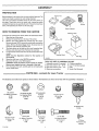
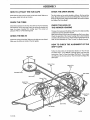
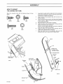
PREPARATION
Before being put in the carton,
carton
was
made to protect
The unit is comptetety
the unit was carefu[iy
the unit during
assembled
except
inspected
The
shipment,
for the items shown
on
this page These items are in the carton with a parts bag which
contains the fasteners to assemble the unit Find and remove these
items,, The fasteners
are shown
Bellows
on the next page,
Owner's Manual
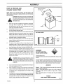
HOW
TO REMOVE
To remove
FROM
THE CARTON
the unit from the carton, follow
1.
Open the top of the carton,,
2.
Remove
the wood
3,,
Remove
the boxes
Remove
sleeve.
frame
the instructions below,.
at the top of the carton_
labeled
(A) and
(B) from
the seat,, NOTE: the seat is covered
Remove
connector
tube
the Grass Bagger
Cover,
and the protective
pad,
the
carton,.
with a protective
the outer
tube, the
4.,
The items shown at the right are in a small unmarked
box.
Remove and check each item Remove the small box°
5.
Cut each corner of the carton
a knife,
NOTE:
See the
the controls,,
Operation
from the top to the bottom
section
6o
Move
7,
Move the lift lever to the HIGH position
the shift lever to the NEUTRAL
for
the
with
location
of
position
TOOLS YOU NEED TO ASSEMBLE
1. Adjustable wrench (2 required)
2. Open end wrench 1/2" - 9/16"
3, Open end wrench 7/16" - 1/2"
4. Blade type screwdriver
CAUTION:
Check the bottom
of the carton for staples,,
Remove any staples that are in the path of the tires.
9,
From the back of the unit, carefully
off the wood frame,
pull the unit backwards
___. PARTS
BAG - contents
The fasteners and other loose parts are shown below,, The fasteners
® @ ©
for Lawn Tractor
THE UNIT
5 Phillips screwdriver
6, Low Tire pressure gauge
7o Knife
8 Socket Set (Optional)
........
are shown at full size with the quantities
in brackets
{ ),
@
(2) Locknut
(1) Flange Hax Nut
(2) Lockwasher
For Battery Terminals
1/_'2B
For Steering Wheel
5/t 6"-24
For Seat
I.Do 5116"
15×66
15x90
18xl 6
[Not shown rut}slzti)
(4) Hub Cap
24582
(2) Ignition Key
91275
(Notshawn full
Size)
(1) Battery
91941
Clip
12) He× Bolt
For Battery
Termlnais
V_"-20x%"
1 x38
F-91726
{2} HBx Bolt
For Seat
(t) Hex Bolt
For Steering
5116"_18x_ls "
tx45
B/16'L24x1
lx66
7
_J_
Wheel
¥0"
(1) Screw
For Battery Clip
26x 184
ASSEMBLY
ii
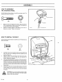
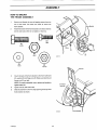
HOW TO PREPARE AND
CHARGE THE BATTERY
ii
Remove and discard
NOTE; Before you install the battery, add the battery acid
the meta_
(Electrolyte) and charge the battery° Battery acid will damage
paint and parts,
WARNING:
Vent Cap
Read the instructions included with
the battery acid container. Protect your hands
_
1.
nd eyes
fromyou.
the battery acid_ Use clothing that
will
protect
If the vent caps are not installed
vent
caps
included
from
with
the
If metal
bag
Read
remove
the
the
instructions
Battery
the vent caps_ Your unit will have one or the
other types of batteries
2_
on the battery,
plastic
tape covers
the vents. Discard
as shown.
the vents,
the metal
remove
the metal tape from
tape.
ii ...................
3.
Pour battery
touches
battery
acid into each battery
the bottom
the battery
4.
Wait
of the vent as shown.
acid above
much battery
the bottom
you charge
20 to 30 minutes
battery
5o
The
the
level
of
described
battery
battery
Discard
with
the battery
Add baking
more
the
solution
Destroy
the container
with
drop
vent
battery
below
the
Correct
Liquid
Level
acid until the correct
any battery
and any battery
soda and mix together
Discard
you can continue
Fill the container
soda
Vent
Install the vent caps_ Wash the
acid container
baking
tf you add too
acid will flow from
water to remove
was not used as follows.
Add
can
in step 3, Add more
top of the battery
6.
acid
acid level is reached.
until
using
the
acid that
half full with watery
the solution
and wash
acid._
a piece
does
container
DANGER
of wood,
not
with
BATTERY
foam.
CAUSE
8o
To prevent accidents, neutralize the battery acid that was not used To
The fumes
neutralize, fill the container half full with water Add baking soda and
mix using a piece of wood until the solution does not foam, Discard the
solution and wash the container with water Destroy the container
from
the battery
charger
a rate of 6 amperes
for 1 hour,
the battery
acid can cause
an
to charge the battery.
is charged,
check
Charge
Do not
add battery
battery
can be
to a charged
External = Wash the area with water, then wash with a solution of
water and sodium bicarbonate
the level of the battery
acid falls, add water.
acid
ANTIDOTE:
at
acid. If the level of the battery
The engine has a 3 amperes
charging
start the engine or frequently
the battery
battery,
BURNS
WARNING;
smoke,
KeepWhen
the battery
you chargethe
away from
battery,
any sparks_
do not
or the result
Internal = Drink large amounts of water milk, or milk of magnesia
Drink water mixed with the whites of eggs_ Call a Doctor
immediately
an explosion.
9.
WILL
Contains sulphuric acid.
Do not let the battery acid come in contact with the skin, the eyes. or the
clothing
Use a 12 volt battery
After
ACID
SEVERE
water..
explosion.
7,
VIEW
you put the vent caps on the
battery° While you wait for the battery,
of the unit°
CUT AWAY
the battery.
before
the assembfy
acid
Do not add the
of the vent.
acid, the excessive
when
cell until the battery
will not stay fully
charge
the battery
system
use the headlight
charged.
every three
Eyes - Flush with water for t5
medical help
If you frequently
minutes
and then get immediate
(if equipped),
For longer
life of the
- KEEP AWAY
months.
POISION
FROM
CHILDREN
D-5213
F-91726
8
ASSEMBLY
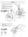
_OW TO ASSEMBLE
rilE STEERRNG WHEEL
Jse the fasteners shown below to install
;asteners are shown at full size
the steering
wheeE The
@
S1eedng
B
ix66
B
t 5×90
Bellows
1
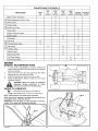
Make sure the front wheels
point forward.
Slide the bellows
over the steering post. Make sure the collar of the bellows
on top. Push on the top of the bellows.
2,,
Attach
the
fasteners
HOW
steering
wheel
as shown
to the
Tighten
TO INSTALL
Use the fasteners shown
shown at full size°
steering
post
is
with
the
the seat, The fasteners
are
e 5699
the fasteners
THE SEAT
below to install
(A)
Ix45
(8)
18×16
1.
Carefully
remove
the protective
from the seat, Do not
bottom of the seat.
2.
3,
Align
the holes
Fasten
the
shown
Tighten
in the
seat
to the
sleeve and the
damage
seat hinge
seat
the
wire
plastic
attached
to the holes
hinge
with
the
to
bag
the
in the seat..
fasteners
as
the fasteners
Check the operating
position
Seat
of the seat. If the seat needs to
be adjusted, loosen the seat adjusting nuts on the seat hinge.
Slide the seat forward or backward along the adjusting holes
as shown.To
keep the seat straight,
align the rear edge of the
seat hinge with the marks on the top of the console_ Tighten
the hex nuts.
4"
Connect
the wire
harness.
Make sure the tab part of the connector,
seat switch
connector,
from
sensor,
the seat switch
sensor
to the wire
Jocks into the latch of the wire
from
the
harness
WARNING:
For correct and safe operation ofthe
unit, connect
the wire from the seat switch
sensor
F-91726
to the wire
harness.
9
Steering Posl
Wheel
= == =l= H =l=l,====,l,l,l,l,l==l,l=ll=l===
ASSEMBLY
= 111i= iH ,lliHi,i,ll
HOW
TO ATTACH
CHECK THE DRIVE
THE HUB CAPS
BRAKE
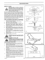
The drive brake can be easily checked as foHows_ Set the parking
brake Move the shift lever to the neutral (N) position Push the unit.
Push each hub cap onto the center' hub of each wheel, Make sure
the washer holds the hub cap in place_
If the rear wheels rotate, adjust the drive brake. Seo "How To Chock
And Adjust
CHECK
The Drive Brako'_
THE TIRES
CHECK THE LEVEL OF
THE MOWER HOUSING
Check the air pressure in the tireSr.Tires with too much air pressure
will cause the unit to ride rough. Also, the wrong air pressure will
keep the mower housing from cutting level, The correct air
pressure (PSI) is 12 PSI (0,B5 kg/cm2),
The lever of cut was set at the factory,, After the u nit is fully assemble,
completely
read the Operation
Section.
Make sure the level of cut is set at the height you like for your lawn,.
CHECK
THE BELTS
Check the operation
of the mower housing° Mow a short distance
and look at the area that was cut. If the mower housing does not cut
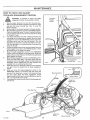
Check the routing of the belts.
Make
sure the belts
Make sure the belts are not twisted.
are inside
level, see the instructions
on "How
To Level The Mower
Housing"_
all the belt guides_
HOW
SHIFT
TO CHECK
THE ALIGNMENT
OF THE
GATE
Follow the instructions
The Shift
_nstructions,
in the Operation
Lever"., If it is difficult
"How
To Check
Section
to change
And Adjust
on "How
To Use
gears, first check the
The Clutch". Then, adjust
the shift gate.. See the irrstructions, "How To Check And Adjust The
Shift Gate",
Belt Guides
Blade Drive
Pulley
Transaxle Pulley
Belt Guides
idler Pulley
Mower Drive
Belt
Stack
Pulley
Idler Put{ey
Belt Guides
F-91726
t 0
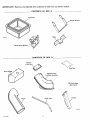
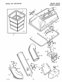
iMPORTANT:
Remove
and identify
the contents
CONTENTS
of each box as shown
OF BOX
below:
A
Containers
Weight Bracket
Hin_
Frame
Mount
Bracket
_L=_
CONTENTS
OF BOX
B
Window
Parts Bag
(In paper bag_
Extension Tube
and Plate Assembly
Fr°ntWi_"
(2) Plastic Bags
(Not shown)
\
Channel
Elbow
D-81_8
F_91726
I 1
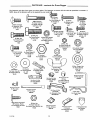
PARTS
BAG - conterlts
for Grass Bagger
The fasteners and other loose parts are shown below. The fasteners are shown full size with the quantities
NOTE:
Some
of the fasteners
will
not be required
for your modoLi_.,
in brackets ().
..,..
_,_"-20 x ½"
(5)Bolt,Special
3
For Outer Tuba (3)
(2) Bolt, Carriage
For Extension Tube
5/16"-18 x ¾"
2x64
(1) Screw
For Rubber Latch
1/_-20 x 1 _
ForFor
Cover
Hinge
Handle
(1) (4)
L4x24
For Center Tube (2)
5/16"-24 x 1% _
6x93
@
(1) Bolt, Hex
For Frame Bracket
½"-13 x t¼_
lx125
(2) Bolt, Hax
For Frame Bracket
5/t6"-1B x 1 _
I x84
4x71
(1_)
(4) Bolt, Carriage
For Front Weight
5/16_-18 x ¾_
#10-t6 x ½" AB
For Window
26x246
2x74
(2) Hex Nut, Flanged
For Latch Pin (1)
For Rubber Latch (1)
¼"-20
@
15x89
For Window
Q
(t) Locknut
For Frame Bracket
(4) Locknut, Flange
For Front Weight
5/16"-18
15x88
151Washer
121 Washer
(Not ShownFullSize)
For Frame Bracket
LD. °39"
17x51
(I) Handle, Plastic
For Cover
54537
;;
(Not
Full Size}
15x109
121 Nut -Flange, Hex
For Frame Bracket
5116"-18
15xl 08
(2) Nut, Wing
For Extension Tube
5/16'_18
@
{Not Shown
#10-24
(4) Nut, Jam
For Front Weight
5/16"-t8
_;_143
For Outer Tube (3)
For Center Tube (2)
18xl 5
For Cover Handle (2)
For Window Ctip (1)
#10-24 X %"
4x21
Clip (1)
15x81
For cover Hinge [4)
For Handle (2)
¼"-20
15x66
131 Screw
(3) Nut, Hax
For Cover Handle (2)
(6) LocknQ
(1) Bolt, Carriage
For Latch Pin
1/4"-20 x s/a"
2x39
Screw
For Elbow
¼" x ¾" AB
26x239
14x83
ShownFull
Size)
(1) Plug, Weight
24863
_
(Not ShownFull
Size)
(3) Cap
For Outer Tube (2)
For Center Tube (1)
54695
(1) Latch, Rubber
{Not Shown
Futl Size|
(1) Pin, Latch
54563
2
(Not Showni_[t Size)
(1) Pin, Hinge
54407Z
For Connector Tube
54416E7011
ForCover Hinge
31x6
(Not shown actual size)
(8} Fastener, Plastic
For Containers (4 each)
193xl
F-91726
151Nut, Hex
For Outer Tube (3)
For Center Tube (2) 5/16"-24
16X32
{NotShownFullSizel
(1) Clip, Window
54571Z
12
(NotShownFullSize}
(1) Bracket
For Extension Tube
54566
(1) Expansion Nut
For Window
28x56
ASSEMBLY
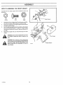
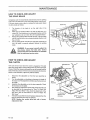
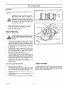
HOW
TO ASSEMBLE
Assemble
the front weight
THE FRONT
support
with
WEIGHT
the fasteners
shown
full
size below,
©
1,
(B)
(A)
(c)
15x 109
2x74
15x88
Assemble
the tractor
the four carriage
as shown,,
bolts
C_
.3_
Weight
Support
(A) and four jam nuts (B) to
Make sure jam nuts (B) are tight°
2,
Fit the front weight
3o
the plug on top as shown,
Set the weight and weight support
into the weight
support
with the hole for
in position
on the carriage
bolts you assembled
in Step 1- Fasten the weight
support
with the four Iocknuts (C} as shown, Make sure Iocknuts (C}
4_
are tight,
Fill the front weight
with
sand,, Install the plug in the front
weight.
on a slope
WARNING:
even.
or where the lawn is rough or not
Use the front weight when you mow
WARNING: Do not ride up or down slopes that
are too steep to back straight up. Never ride the
unit across a slope. See the "Slope Guide" in the
back of this book for information on how to
check slopes_
F-91726
O-e130
13
Weight
Support
iii
iiiiiii1,,111
ASSEMBLY
H =l= =H,N
::::::::::::::::::::::::::::::::
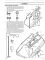
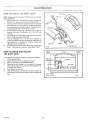
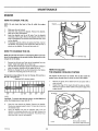
HOW TO MOUNT
THE FRAME ASSEMBLY
Remove and discard the two self=tapping screws from the
rear of the framer Use these two holes to mount
the
frame bracket_
2.
Frame Bracket
Attach the bottom of the frame bracket to the frame with hex
,
bolt (A} and Iocknut (B) Do not tighten at this t_me=
(A)
lx125
(A)
0-8t19
15x41
(D)
17x51
__
(E)
15x108
Channel
3_
Attach the back of the frame bracket to the frame with bolts
(C), washers (D) and flange nuts (E)._Make sure botts (C) and
flange nuts (E) are tight.
NOTE: For easier assembly, use a ratchet and socket to
"U" Shape
tighten bolts (C).
4_
Tighten bolt (A) and Iocknut (B}.
5..
Slide the channel in to the "U" shape opening in the top oftha
Opening \
frame bracket as shown,
D-8_20
F-91726
14
Frame Bracket
From the right side of the unit, install
6,
the channel
channe_
Mount
7_
as shown,
Rotate
the channel
the channel
pin throug
(F)
h
pin to lock the
in place,
the outer tube to the channel
as shown,
Make sure the
holes on one end of the outer tube are on the right side of the
unit, Use the fasteners
fasteners
shown
full size below
Make sure the
(G)
are tight_
CAUTION:
If the fasteners
are tightened
outer tube
can be damaged.
© @
IF)
(G)
6xg3
t8x 15
too much,
the
(H)
15x32
Make
sure
these
holes are to the
right side of the
unit
Channel Pin
Rotate
Channel Pin
Counterclockwise
e-8!21
8
Mount
the center tube to the channel
the fasteners
CAU'flON:
9.
as shown
Make sure
are tight,
If the
fasteners
are tightened
center
tube
Attach
the caps to the end of the tubes
too
much,
the
can be damaged,
as shown
Channel
Center Tube
(F)
(F}
6x93
G Q
(G)
! 8x 15
F-91726
(H)
15x32
15
IIIHII=I=IIIll i= i
ASSEMBLY
HOW
1o
TO MOUNT
Assemble
THE COVER
the hinge
to the cover with the fasteners
full size below,. Push tire hinge toward
Make sure the screws
hinge,, Tighten
2
Attach
are at the bottom
the fasteners
(a)
4x24
(c)
(D)
4x21
15x81
nut (F) into the slot in the cover as shown,,
the window
to the cover with the fasteners
as shown°
Make sure the cover fits between
the plastic
cover,
Push on each side of the
at the end of the window°
window
until
Fasten
with
the two
screw
on the inside
window
clip with
screw
plastic
channel.
with
flange
are locked
Align
the hole in the cover°
and the
in position°
Put the window
of the window,.
clip
in
the hole in the
Fasten
the window
(C) and nut (D) as shown,
Set the cover in the operating
tube assembly
tabs
(E) as shown,
position
clip with
4.
15x66
Push expansion
Mount
as shown.
the fasteners,
_(A)
3_
of the holes in the
the fasteners.
the handle to the cover with
Tighten
shown
the top of the cover,,
as shown.
position
D-S124
on the top of the outer
Align the holes in the hinge and the
Fasten the cover and hinge assembly
hinge pin and hair pin shown
to the channel
full size below.
),
W_ndow
Plastic Tab
31x6
Pfastic Flange
(El
26_.46
IF)
28x56
O
(H)
54407Z
F-9t726
(H)
!6
................................
i,, ,lui un,lllli,l_Jii
ASSEMBLY
HOW
1,,
TO MOUNT
Assembfe
latch
fasteners
shown
THE EXTENSION
pin (A)
to
the
TUBE
extension
tube
with
the
below
A
54563
15x89
2x39
A
B
C
2,
Move the lift lever to the highest cut position,
3.
Disconnect
the wire to the spark plug. Raise the deflector,
Rotate the blade away from the discharge openir;g, Remove
the carriage
shown.,
bolt and
Iocknut
from
the
mower
housing
as
Deflector
Bracket
D-B126
_
4,
Slide
the extension
tube
under
shown_ Fasten the extension
housing
5-
Mower Housing
has of
sharp
edges_ Always
b eARNING:
careful ofThe
the blade
position
the blade.
with
the bolt (D) and wing
sure the wing nut is tight,
ff not assembled
to the extension
position at the back of the
extension tube and the bracket
as shown.
Make
the deflector
bracket
as
tube to the front of the mower
sure the wing
nut (E) as shown.
tube,
Extension Tube
Make
put the bracket
in
extension
tube_ Fasten the
with bolt (D) and wing nut (E)
nut is tlght,,
Deflector
Bracket
2x64
D
14x83
E
a-8151-2
F-91726
17
ASSEMBLY
HOW TO MOUNT
THE CONNECTOR
Mount
the
connector
TUBE
tube
with
the
fasteners
shown
full
size
1
below,,
Assemble
the handle
tube
the fasteners
with
screwdriver
15x89
and tighten
the
3,
Fasten the elbow
4x24
4,
5_
cover,
(E)
the
in the hole of cover
NOTE: To help the elbow
with
the hole
in the
tube with the self=tapping
screw
until
the head
of the
put wax or polish
efbow
7
rubber latch is aligned whh
Slide the bottom
end of
tube
and
you open
or close the
on the elbow,
Rotate
extension
the
as shown,,
slide when
6.
15x66
connector
tube
assembly
the latch pin
the connector
Lock in place with
tube
the rubber
until
the
over
the
latch,
Elbow
hole in
with hole in elbow
Conoector
Tube
Slide elbow into
hole in cover_
Lock in piece
whh rubber latch
D-8133
CoRRecter
Tube_
Handle,
Rubber Latch
(D)
D-S129-f
F-91726
18
a
Move the lift lever to the lowest cut position_
Hold tire handle on the connector
tube,, Put the end of the
elbow
4x71
tube
to the connector
as shown
Tighten
touches the elbow,
with
Iocknuts,
Atign the hole in the connector
elbow as shown_
screw
screw
latch to the connector'
as shown,_ Hoid the screws
2,
(B)
26x239
and the rubber
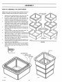
ASSEMBLY
HOW
TO ASSEMBLE
THE CONTAINERS
NOTE: There is only one way that these containers can be put
together. Carefully read and follow the instructions below_,
1
Separate
the six container
have 2 tops, 2 middle
2,
Look
for a number
numbers
3.
into two
on
one
side
groups
pieces
of each
You will
top
piece
The
for the two top pieces are I arid 3. Set the two top
with
Look for two
on one side of each middle
piece
numbers
the numbers
the flange
has the numbers
piece has the numbers
piece_ One
1 and 2, The other
3 and 4. Match
1 and 2 with
part up as shown,
top piece
the middle
middle
piece with
1. Set the middle
piece
inside the matching
top piece as shown
Match the middle piece with numbers 3 and 4 with top piece
3 as shown
piece
Set the middle
piece
inside
the matching
top
as shown,,
5,
Look for a number
6,
numbers for the two bottom pieces are 2 and 4o
Match bottom piece 2 with the top piece 1 and middle piece1
that
on one side
has the numbers
piece inside
7
Match bottom
of each bottom
piece
1 and 2. Set the matching
the middle
piece
bottom
piece 4 with the top piece 3 and middle piece
bottom
TOP PIECES
Put one foot inside the three pieces and lift the top piece until
the three pieces connect
together
of each piece are locked
9,
The
as shown
that has the numbers
3 and 4, Set the matching
piece inside the middle piece as shown_
8,
PIECES
as shown,
pieces on the ground
middle
4.
pieces
and 2 bottoms
BOTTOM
D_8177
Make sure all four corners
i
together.,
Fasten the top and middle
Flange
of Top
GROUND
pieces of each container
together
using four fasteners for each container
Push each fastener
into the hole in each side of the container
from the inside
as shown,
Fasteners
(No_ shown
_ctua!
s_ze}
BOTTOM PIECE
MIDDLE PIECE
TOP PIECE
F-91726
19
i
ASSEMBLY
i
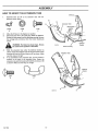
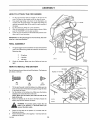
HOW
1
TO ATTACH
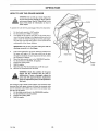
Tilt the
seat forward
Two
3,.
4,
plastic
bag
Hold
linings,
included
with
optiona]
accessories
the handle
not shown
that
on the back
of the
in the illustration,
The plastic
are
bag linings
can be used for easy removal
Put the plastic bag linings in to the containers
Slide the containers
on to the frame tubes as shown
5,
are
of
Make
is to the rear' as si_own
Lower the cover Pull back on the handle and push the cover
the grass,,
down unti_ it locks into place
IMPORTANT:
For the grass bagger to work
must be in the down position,.
FINAL
1,
correctly,
I
the cover
ASSEMBLY
The grass bagger
has two containers.
For easy removal of the
grass, use a plastic lining inside the container
following
Check
2+
Use one ofthe
sizes°
e
33 gallons
e
4 bushels
e
145 litres
the fasteners°
0-8131
;_
Make
sure that
alt bolts
and nuts are
TO INSTALL
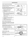
THE BATTERY
Use the fasteners shown below
are shown at full size,
(A)
lx38
1o
to install the battery,
The fasteners
(B)
(C)
t 5x66
26x184
Tilt the seat forward Install the battery tray_ Make sure the
drain on the bottom ofthe battery tray goes through the hote
in the frame as shown,
Set the battery in the battery tray, Make sure the battery
terminals are toward the front of the unit,
NOTE: Make sure the battery fits under the tabs at the
back of the unit.
Fasten the battery clip in the slot in the frame,, Attach the
battery clip with the fastener as shown,
2,,
3°
cable
to theTopositive
terminal
before
WARNING:
prevent(+)sparks,
fasten
the you
red
connect the black cable,
_
4.
Fasten the red cable
fasteners as shown_
to the positive
(+) terminal
5,
Fasten the black cable to the negative
fasteners as shown,
(--) terminal
F-91726
with
Caution
to
tight,,
HOW
i
and lift to raise the cover
the grass bagger
sure the "CAUTION"
illll
THE CONTAINERS
cover,, Pull back on the handle
2
lllll
the
with the
2O
rear
i
,
,
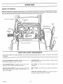
OPERATION
KNOW
THE
PRODUCT
Before you operate the unit, read this instruction
When
you read this instruction
follow
the operating
Position
book° If you understand
book, compare
instructions
the illustrations
and the safety
rules
the unit and how the unit operates,
to the unit. Learn the location
Keep this
instruction
book for future
you will get the best performance.
of the controls.
To help prevent an accident,
reference
w _en Enga(
Button
!
Parking Brake Lever
Clutch/Brake
lgnitloniLight
Pedaf
Switch,
Blade Engagement
Control
O
Q
Position when Disengaged
ill
ill,ii
u i
i
ii ii
ii
MEETS
Sears Mowers
Commission,,
conform
i illlUHlll
BLADE
to the safety
i Hu,
.ll
ENGAGEMENT
lever to start
standards
and stop
CONTROL
the rotation
LEVER:
UUlmlIHH
National
Use the control
SWITCH:
The switch
PARKING
The first
has two funct}ons
The second
Standards
when
IGNIT|ON/LIGHT
function
ii ,i,,ll
i ,, illUll,,i
,,i
i
Institute,
and the US
Consumer
Product
Safety
I I III,H
of the blade
the engine
ii
REQUIREMENTS
'llHJl
PEDAL:
The pedal has two functions
The second function is a brake
is for starting
ii
of the American
CLUTCH/BRAKE
function
is a clutch
first function
i ,llllll,lll,ii
CPSC SAFETY
BRAKE:
you leave
LIFT
LEVER:
attachment
The
SHIFT
unit
is to
Use the parking
brake
to engage
the brake
the unit
Use
the
lift
lever
to
change
the
height
of
the
LEVER: Use the sh_ft lever to change the speed of the
turn on the headlight
THROTTLE
CONTROL
LEVER: Use the throttle control to
increase or decrease the speed of the engine
F191726
2t
OPERATBON
The operation
foreign
thrown
result
in severe
safety
glasses
your
lawn
eye
the
spectacles
available
at Sears
TO USE THE
can result
eyes,
damage°
shields
and
Wide
over the
mower
in the
or eye
mower
recommend
HOW
of any lawn
objects
Retail
wear
Safety
Completely
for
3,
Remove
your
t
from
release the paddng
will hold the unit,
I
To
release
the
clutch/brake
automatically
parking
FUNCTION
pedal
and
brake,
completely
The
brake
Trimming
Snow
the
control
HOW
1,
unit
2
brake.
Move
the blade
to the DISENGAGE
position.
and remove
the ignition
Bagging
the
blade
forward
grass
,,! or 2
mowing
to stop the
3.,
Move
4_
Set the parking brake,.
5.
Move the throttle
&
To stop the engine,
Remove
control
to the
Light
DISENGAGE
mowing
lever to the NEUTRAL
control
position,,
to the SLOW
turn the ignition
Snow
TO US[ = TH[= SHIFT
HOW
TO CHANGE
1.
the direction
Completely
CHOKE
key to the OFF position,
"°7"
Attachments
L[=V[=R
push the clutch/brake
the steps
HOW
below:
pedal _orward
I.
3
depress
Before
the
you clutch/brake
change directions
pedal,,
of
Make
sure the shift
Slowly release the clutch!brake
foot on the clutch/brake
pedal
F-91726
2 or3
TO USE THE SHIFT-ON-THE-GO
While the unit moves forward,
you can select any forward.
speed Just move the shift lever to the next faster or next
lever engages
pedal
2,
into the shift
Do not ride with
speed,
You
do
not
have
to use the
clutch/brake
pedal
Pull the shift lever toward the seat until the lever disengages
from the shift gate_ Move
the shift lever to FIRST or
REVERSE,
gate
6
SLOW-F_:r
slower
2.
""
DIRECTIONS
of the unit, follow
WARNING:
travel,
fully
O5
position,
the key,
HOW
4or5
Blade
Pull Behind
To change
,2o!3
on the pedal.
engagement
position.
the shift
i --
key.
Normal
pedal completely
Keep your foot
Move
mm
CHOKE
TO STOP THE UNIT
Push the clutch!brake
I
Thrower
:z
Set the parking
Stop the engine
THROTTLE
will
WARNING:
Before
you leave
the operator's
position, move the shift lever to the neutral
(N)
engagement
LEVER
,, =,,,,u
brake
push
parking
SHIFT
then
Make sure the parking
pedal
forward.
release,
position+
i J
e-5732
pedal forward.
the clutch!brake
brake lever
Ga
I
brake lever_
foot
Shift
!
Stores.
MOWER
push the clutch/brake
Lift the perking
tShlftLever
glasses.
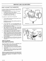
HOW TO SET THE PARKING BRAKE
2
i[
We
Mask
safety
or Catalog
1
starting
mowing.
or standard
in
can
Always
before
while
Vision
which
The shift lever positions
in the chart
for operation
of your unit are shown
NOTE: Belt noise can occur when the clutch is engaged_ This
noise is normal and does not affect the operation of the unit°
your
22
OPEBATnON
i
HOW
TO USE THE THROTTLE
Use the throttle
control
engine_
1
To start
a cold
CHOKE
2,
The
to increase
engine,
position
lever
HOW TO OPERATE WITH
THE MOWER HOUSING
the speed of tile
to the
For transport
throttle
with
a detent,
using a grass bagger,
For maximum
also for a cooler
FAST position,
The
the
is marked
and when
the FAST position
4,,
CONTROL
or decrease
move
,
START
WARNING: The deflector is a safety device,, Do
not remove the deflector° The deflector forces
the discharged material toward the ground.
Always keep the deflector in the down position.
If the deflector is damaged, replace it with a
factory replacement part.
or
position
FAST
operations
3,
ii
running
charging
engine,
For normal
move the lever to
of the battery
aperate
the engine
and to tow pull behind attachments,
control
engine
to the needed
governor
performance,,
move the
speed,
is set at the
Do not
and
in the
adjust
factory
for
the governor
to
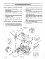
TO CHANGE
THE CUTTING
HEIGHT
button
the
forward
to release the lever. Move
to lower the mower
can be set from
2 to 4 inches
you ride on a sidewalk
or a road, move the lift lever to the hightest
position
the
and
DISENGAGE
move
blade
engagement
control
to
to a lower
5o
position,
Push the clutch/brake
6o
Move the shift lever to one of the speed
When
bagger,
control to the SLOW position°
engagement
Control
to the
pedal
you mow
put the shift
completely
in heavy
lever
Slowly
Move the throttte control to the FAST position
the
move
of the blade engagement
Use the blade engagement
the blade
1
Make sure the level of cut, set at the factory,
If the mower
ENGAGEMENT
on "How
section.
speed
housing
is still correct,
look at the area that was cut.
does not cut level, see the instructions
To Lever The Mower
Housing"
in the maintenance
control in the illustration.
control to start and stop the rotation
WARNING: For better control of the unit, always
select a safe speed.
of
position
Move the control
the blade°
Note:
If the
lever to the ENGAGE
engine
stops
when
position
you engage
to rotate
the blade{s),
HOW
TO OPERATE
Move the control lever to the DISENGAGE position to stop
the rotary blade. Before you feave the operatoKs position,
make sure the blade has stopped
4,
Ifyouneedto
lever to another
setting,
the seat switch is not activated.
Make sure you sit in the
middle of the seat. Also, make sure the wire is connected
to the seat switch,
3
a
Before you start the engine, make sure the centre! lever is in
the DISENGAGE
2,
with
speed,
pedal.
the shift
After you mow a short distance,
See the location
or mow
B°
9
BLADE
settings°
grass
in the slowest
release the clutch/brake
ENGAGE
forward,
7°
go faster or slower,
position
HOW TO USE THE
CONTROL
position°
Move the throttle
Move
the blade
lever
When
housing
in high or thick
first and then lower
3.
4°
NOTE:
housing and back to raise the mower
housing. The cutting height
the engine_
the mower
the
Push the
of the lever
Move the lift Iever to a height of cut position,
maximum
increase
To change the cutting height, raise or lower the lift lever
on top
Start
grass, cut the grass in the high position
speed of the engine
HOW
1
2+
Before
controI
lever to the DISENGAGE
or a road,
move
the
position,,
WARNING: Always keep your hands and feet
away from the blade, deflector opening, and the
mower housing when the engine runs,
HOW
TO TRANSPORT
To transport
the unit, follow
1.
the
Move
blade
14
the steps
2+
Do not stop or change
parking
3+
to the
DISENGAGE
Raise the lift lever to the HI position.
3,,
Move the throttle
and FAST
4
To go faster,
control
move the shift
to
a position
4+
between
lever to a faster
SLOW
5
23
settings
on a hill
If you must
ke pedal forward
and set the
brake,
speed,
Slowly
the pedal
If you must stop or eta rt on a hill. always
you release
have enough
the brake
space
and engage
Be very careful when you change directions
on a hill, When
on a slope or in a turn on a hilt, move the throttle control to the
SLOW
F-91726
speed
push the clutch/bra
for the unit to roll when
the clutch.
speed
lever to the
To start again, make sure the shift lever is the slowest
Move the throttle
control
to the SLOW position,
release
position.
2
a hill, move the shift
speed.
stop, quickly
below,
control
Before you ride up or down
slowest
THE UNIT
engagement
ON HILLS
WARNING: Do not ride up or down slopes that
are too steep to back straight up. Never ride the
unit across a slope. See the "Slope Guide" in the
back of this book for information on how to
check slopes,
rotating,,
you ride the unit on a sidewalk
THE UNIT
position
to help prevent
an accident.
HOW TO USE THE GRASS
BAGGER
WARNING: Do not ride up or down slopes that
are too steep to back straight up. Never tide the
unit across a slope.. See the "Slope Guide" in the
back of this book for information on how to
check slopes..
To operate the unit with the grass bagger,
control
follow
1,
Put the throttte
2,
Put the shift
lever in FIRST (1) position
3,
If the height
of the grass is more
move the mower
grass.. Lower'
cutting
than 3-1/2
to the highest
the mower
width
I
the steps below.
in FAST position
housing
You also can mow
le
housing
high thick
of the mower
inches
position
(9 cm),
and cut the
Contalners
and cut the grass again
grass at 1/2 to 2/3 of the full
housing
IMPORTANT: Do not cut wet grass. Wet grass will not
discharge correctly in to the bagger.
4
Look at the wlndow(s)
in the cover, When the containers
full,
to fill the
grass
will
begin
cover
which
are
can be seen
Frame Tubes
t
J
through the window(s}, As soon as grass can be seen, empty
the containers
as follows,
5
6
Move the blade control lever to the DISENGAGE
Put the shift lever in NEUTRAL (N) position,
7
Engage the parking
8
9
Stop the engine.
Raise the cover,
10o
Remove
position,
Frame_tTubea
D-S13_
brake_
Pull the handle
the containers
from
back and lift the cover
the frame,
The connector
tube
is made of clear pEastic, if the connector
becomes
with
grass,
and the
extension
remove
tube_ Before
and clean the connector
you remove
the connector
tube
tube
tube,
stop the unit as follows_
1,
Put the blade control
2_
Put the shift
3.
Engaged
4.
Stop the engine.
F-91726
__C
a
ution
to rear
WARNING:
Check the condition of the grass
bagger and the connector tube for wear or
deterioration, tf worn or damaged, replace the
parts only with approved factory replacement
parts. For replacement parts, see the parts list in
this book.
filled
_
lever in the DISENGAGE
lever in neutral
the parking
position
position..
brake.
24
OPERATRON
BEFORE STARTING
THE ENGINE
HOW
TO START
WARNING:
The electrical system has an
operator presence system that includes a sensor
switch mounted in the seat. These components
tell the electrical system if the operator is sitting
on the seat° For your protection, always make
sure this system operates correctly. This system
will stop the engine when the operator leaves
the seat if the blade engagement control is
engaged.
CHECK OIL - Add as needed
NOTE;
runs.
Do
1,
Make
2.
Clean
Wipe
3_
Insert
not
check
the
level
of the
oil while
the dipstick,
Remove
the
engine
sure the unit is level,
the
area around
the oil from
until
the dipstick,
the dipstick.
the dipstick
clockwise
into
the oil
it is tight,
fill tube
Remove
Turn
the dipstick
the dipstick,
Check
the oil
NOTE: The engine will not start un!ess you depress the
clutch/brake pedal, move the shift lever to the NEUTRAL
position, and move the blade engagement control to the
DISENGAGED position°
level on the dipstick., The oil level must reach the FULL mark
on the dipstick.
4,,
If necessary,
add oil until
the oil reaches
the FULL mark on
the dipstick
The quantity of oil needed from ADD to FULL is
shown on the dipstick_ Do not add too much oil,
t_
Fill the fuel tank
2.
3,
with
regular
unleaded
gasoline.,
is fresh and clean_ Leaded gasoline
and shorten
the life of the valves.
Make
sure the
gasoline
A mixture
(called
Do not use premium
unleaded
of alcohol
gasoholl,
(ethanol
will attract
or methanol)
moisture
and cause
deposits during storage. While the unit is in storage,
in the fuel can damage the fuel system,,
To prevent
engine
problems
fuel system
before
storage
tank° Start the engine.
the
carburetor
with
the
fuel
of 30 days
Let the engine
are empty.
After
system,
or longer°
run until
storage,
make
instructions
for additional
or carburetor
cleaner
cleaner
damage
settings
the
7,
you use
information°
in the fuel tank
If
section,
1.
The engine
2
A change
3
A 40 ° change
in the operation
was adjusted
at 80 ° at the factory
4.
The engine
F-91726
has a loss of power
from
summer
is operated
or does not run smooth_
to winter
above
operation
temperature.
4,000
After
the
Before
minutes
position
the engine is operated
under the following
conditions,
you can
adjust the carburetor
mixture. See "How To Adjust The Ca rburetor"
in the maintenance
tf the engine
engine
CHOKE to a needed
the fuel
are for most conditions
control
Completely
push
the
to the CHOKE position,
does not start
control
The carburetor
feet
25
you
begin
after
four or five
to the FAST position°
to start the engine°
If the engine
TROUBLE
SHOOTING
CHART°
can occur.
for the carburetor
the throttle
move the throttle
CARBURETOR
factory
seat.
Keep your foot on the pedal
the shift lever to the NEUTRAL (N) position
the blade engagement
control
to the DISENGAGE
NOTE:
WARNING:
Always use a safety gasoline
container. Do not smoke when adding gasoline
to the fuel tank. Do not add gasoline when you
are inside an enclosure,, Before you add
gasoline, stop the engine and let the engine coot
for several minutes.
The
the
Turn the ignition key to the START position, Release the key
when the engine starts,
6,
sure
of
pedal forward,
Move
acid
empty
Move
Move
middle
5o
the acids
Drain
Never
or permanent
the
4.,
and
the fuel lines and
fresh fuel. See the storage
use engine
in
position.
will increase deposits
gasoline,
CAUTION:
Sit
clutch/brake
ADD GASOLINE
gasoline
THE ENGINE
starts,
move
the
will not
start,
throttle
tries,
Again
try
see the
control
from
speed,
work,
let a cold
engine
run for several
To start a hot engine, move the throttle
between
FAST and SLOW
control
to a
OPERATION
OPERATING
1.
2,
TIPS
Check the blade engagement
control
For the blade(s)
be correct
correctly,
to disengage
for correct
adjustment.
the adjustment
5,
must
Before
you make an inspection,
carburetor)
or repair,
is disconnected_
Before you use the unit, check the oil in the engine and add oil
6_
if necessary
Make sure the seat switch
connected,
the engine
wire is connected,
If the engine will not start, first make sure the wire is attached
to the spark plug,,
7,
For longer
tlfe of the
three month&
4,
Make sure all the belts are inside alf the belt guides_ See the
instructions
on how to remove and install the motion dt'ive
8.
Use the shift lever
throttle
control
and mower
9
Belt noise
can occur
when
This noise
the unit_
is normal
and
MOWING
1
AND
For a lawn
BAGGING
to look better,,
mower housing,,
the maintenance
2o
For the mower
the correct
3,
belts,
See "How
section_
housing
amount
check
the cutting
leveF of the
To Level The Mower
Housing"
9
in
Keep the
of air pressure
blade(s)
sharpened.
(PS!},
10
the blade
replace
If the blade is
the blade
Also, make
11o
Worn
blades
will
cause
6,
Do not
cut or bag
discharge
correctly
Use the left
side
grass
that
the
Wet
grass will not
Let the grass dry before
of the mower
housing
13
near an
object.
7..
Discharge
the cut grass onto the mowed
more even discharge
8.
When
that
you mow
are& The result is a
of cut grass.
large areas, start
the cut grass will discharge
by turning
away
from
driveways,
etc_ After one or two rounds, mow
direction
making left turns until finished,
F-91726
charge
If the wire is not
the
the ground
the blade
battery
speed,
or clutch
does not affect
every
not
the
is engaged
the
operation
to the right
shrubs,
engine
For better
so
fences,
in the opposite
26
position
cutting
the
performance
operate
to decrease
the mower
lower
you use a bagger,
the shift
cutting,
to trim
When
in FAST
12,,
is wet.
For better
then
cut grass, always
FAST position,,
ends of the grass to turn brown,
5.
to change
First cut with
position
and
second cut,.
sure the nut for the blade is tight,
4,
battery_
If the grass is very high, cut two times
the engine
to cut level, make sure the tkes have
immediately
for the
of
TIPS
Every time you use the unit, check
bent or damaged,
(except
will not start
3,
drive
adjustment
make sure the wire from the spark plug
the
operate
the load on
housing
mower
in the HIGH
housing
for
and an even discharge
engine
with
the engine
the
of the
throttle
lever in first or second
performance
and a quality
cut, mow
gear,
with
speed gears.
After each use, clean the bottom
and top of the mower
for better performance.
help prevent a fire,
a clean
Also,
in
with the throttle
and the shift
lever in one of the slower
the
mower
housing
housing
will
MAINTENANCE
Blade,
Inspect
FIRST
2
HOURS
EACH
USE
PROCEDURE
SCHEDULE
EVERY
25
HOURS
B!ade Engagement
_
Brake,
T
Clutch,
O
Shift
Control,
Check
X
Check
X
Lever, Check
X
Tires, Check
Check
& Char_3e
_ Battery, Ctean
Lubrication
1
Coolin 9 System,
i_
Oil, Chan£1e
Air Filter,
Muffler,
X
,
Clean .........
Fuel Filter,
RECOMMENDATIONS
1.,
owner's
which
responsibility
extends
to correctly
the iife of the product
maintaln
coverage
Once a year you must check the spark plug,
lubricate the unit, and clean the air filter.
3_
Check
the fasteners
4.,
Follow
the Maintenance
Section
to keep your
unit in good
(except
carburetor),
Before
you make
an
the wire from the spark
or
repair,
inspection.
plugo
condition.
Lubricate
Apply
Apply
grease
the areas shown
grease
to the
with
a brush
C
steering
with
engine
oil.
to the areas shown,
gear assembly.
NOTE: If the unit is operated
in dry areas that
dry graphite spray to lubricate
the unit.
have sand,
CAUTION:
Do not lubricate
the nylon bearings
wheeiso Oil or grease will damage the bearings,,
F-91726
brake,
TO LUBRICATE
'=='_li_
NOTE;
drive
and make sure they are tight.
adjustment
WARNING;
disconnect
WHERE
C
this
and to maintain
2.
operating
X
X
X
X
X
X
X
X
X
MOWER
warranty
X
X
Replace
GENERAL
product
X
X
Plut3, Replace
It is the
X
X
Plug, Check
Spark
X
X
Clean
Check
Spark
X
X
Oil, Check
G
E
BEFORE
STORAGE
X
Check
......
Battery,
EVERY
100
HOURS
X
& Sharpen
RT
EVERY
50
HOURS
use a
for the front
27
STORAGE
DATES
MAINTENANCE
_NSPECT
BLADE
WARNING:
Before you inspect
or remove
the
blade, disconnect
the wire to the spark plug, If
the blade hits an object, stop the engine° Check
the unit for damage
The blade has sharp edges,.
When you hold the blade, use gloves
or cloth
material
to protect
your hands,.
If you keep the blade sharp and inspect the blade for damage, the
blade will cut better and be safer to operate, Frequently
check the
blade for excessive
wear
cracks, or other damage
Frequently
check the nut that holds the blade_ Keep the nut tight If the blade
hits an object, stop the engine
Disconnect
the wire to the spark
plug, See if the blade is bent or damaged
Check the blade adapte_
for damage
Before you operate the unit, replace damaged
parts
with a replacement
part from the factory
Every three years, have
an authorized
service person inspect the blade or replace the old
blade with a replacement
blade from the factory
\,
Mandrel
Blade
Adapter
Blade
Hi-Lift
Edge Up
HOW TO REMOVE AND INSTALL THE BLADE
1
2,
3
4,
5
6,
7
8,
9
10
Remove the mower housing,_ See the instructions on "How
To Remove The Mower Housing".
Use a piece of wood to keep the blade from rotating
Remove the nut that holds the blade.
Check the blade and the blade adapter
according
to the
instructions
for "Blade Service"
Replace a badly worn or
damaged blade with a replacement
blade from the factory
Clean the top and bottom of the mower housing, Remove all
the grass and debris.
Mount the blade and blade adapter on the mandrel as shown.
Mount the blade so that the hHfft edges are up as shown
If
the blade is upside down, the blade will not cut cot rectly and
can cause an accident
Blade
t
HOW TO SHARPEN
Always
A loose
,
)
I
Betleville Washe_'
Washer
Fasten the blade with the odginat washers
and nut, Make
sure the outside rim of the belleville
washer is against the
blade as shown,.
Tighten the nut that holds the blade to a torque of 30 foot
pounds (41 5N-m)
Connect the wire to the spark plug,
WARN1NG:
the blade_
accident=,
/
I
Nut
D 41563
keep the nut tight that holds
nut or blade can cause an
THE BLADE
,&
WARNING:
Vibration
can be caused if the blade
is not correctly balanced or if the blade is damaged.
A blade that is damaged with cracks can break
and cause an accident_
Keep a sharp edge on the blade A blade that is not sharp will cause
the tips of the grass to become brown.
1.
Sharpen the blade two times a year or every 25 hours,
2
Remove the biade according
to the instructions
in "How To
Remove And Instalt The Blade",
3
Clean the blade with a brush soap and water
Check the
bfade Look fo_ cracks, nicks, or other damage
Replace a
badly worn or damaged blade with a replacement blade from
the factory
4
Sharpen the blade with a file Make sure you keep the original
bevel angle.
5
Make sure the blade is balanced
Use a screwdriver
and hold
the blade paralleJ to the ground as shown
A blade that is
balanced
will stay parallel to the ground
if the blade is not
balanced,
the heavy end will rotate toward
the ground
Sharpen the heavy end until the bfade is balanced,
6
A new blade witl cut better than a badly worn blade Every
three years, have an authorized
service person inspect the
blade or repiace the old blade with a replacement
blade from
the factory
7
Assembie the blade according
to the instructions
"How To
Remove And Instafl The Blade"
F-91726
D_4169-1
Ground
28
, lure ,u
mH..HH
,.,..,
MAUNTENANCE
HOW TO CHECK AND ADJUST
THE BLADE ENGAGEMENT
CONTROL
WARNING:
engagement
1
Stop
2
Before you adjust the blade engagement
control lever, check
and level the mower
housing.
See "How
To Level The
3
4
5..
the engine..
Completely
To prevent
an injury, the blade
control must operate correctly..
Disconnect
the wire
from
the spark
Engaged
Position
pEug..
Mower Housing"
Set the height of the mower housing in the lowest position.
Move the blade engagement
control to the ENGAGE position..
(_heck the blade drive spring.. The end of the plastic indicator
must be aligned with the last coil of the blade drive spring
(+ 1/B inch / 3 mm)_
If the plastic indicator is more than 1/8 inch (3 mm) from the
last sprihg coil, an adjustment
is needed. Move the blade
engagement
control to the DISENGAGE position. Disconnect
the blade control
rod from the pivot bracket_ Turn the
adjustable
nut clockwise
tO increase the length of the coils
Turn the adjustable
nut counterclockwise
to decrease the
6
length of the coils,
Connect the blade control
rod tO the pivot bracket.
blade engagement
control to the ENGAGE
the adjustment
of the brade drive spring..
7
8.1
Disengaged
Position
Move the
position
Check
Move the blade engagement
control
to the DISENGAGE
position., Check the operation
of the blade brake. Rotate the
pulley with your hand Make sure the blade brake pads press
tightly against the pulleys.
Move the blade engagement
control to the ENGAGE position_
Check the blade brake pads If the blade brake pads are
excessively
worn or damaged,
replace the blade brake
assemblies.. Correct replacement
parts and assistance
available from an authorized
service center
Attach the wire to the spark plug. Mow for a short distance
and again check the operation
of the blade engagement
control.
10.
When
you move the blade engagement
control
to the
DISENGAGE
position,
all movement
will stop within five
seconds if the adjustment
is correct. If all movement
does
not stop,
again
adjust
the blade
engagement
beginning
with the first step If you need assistance,
unit to an authorized
service center..
lfyou replace ti_e mower
control lever..
Blade Engagement
Control
Lever
pad
are
9
11.
Completely
Blade Control Rod
control
take the
(_
drive belt, adjust the blade engagement
Plastle,ndicater
Brake Pad
Against Pulley
Adjustable
Pivot
Blade Brake Pad
D-5707-t
Blade Drive
Spring
F-91726
--
29
Mower
Drive Belt
J
MAnNTENANCE
HOW TO CHECK AND
THE DRIVE BRAKE
ADJUST
Completely
pedal forward,,
brake
push the clutch/brake
Movethe
If the rear wheels
the drive brake
rotate,
adjust
Push the unlt.
the brake pads
2
gearbox
Make sure the parking
location
of
tile
brake
is on
brake
the
right
rear wheels
do not turn when
the parking
side
is set and the shift
(N), Turn the hex nut in a clockwise
Release
Adjust
Brake Arm
The
3
or replace
as follows
1
neutral
Set the parking
shlfttevertotheneutral(N)position,
of
the
lever is in
direction
the unit is pushed
untit the
forward,
brake and push the unite if the unit does
not roll, turn the hex nut in a counterclockwise
direction
until
the unit rolls,
4
Set the parking brake. Push the unit. If the rear wheels do not
turn, the brake is correctly
adjusted
Release the parking
brake
WARNING:
if you cannot correctly adjust the
drive brake, replace the brake pads, Correct
replacement parts and assistance are available
from an authorized service center,
HOW TO CHECK
THE CLUTCH
D-5720
AND ADJUST
Adjustable
If the unit will not move when
the clutch
slips when going uphill or when pulling
is engaged
Nut
or if the belt
a toad, the motion
drive belt
is loose. Check the clearance between the rear of the pedal and the
back of the hole as shown_ If there is more or less than the clearance
shown
in the illustration,
adjust
the pedal
the adjustable
nut from
1=
Disconnect
shown
2.,
Turn the adjustable
nut clockwise
the clutch rod_ This adjustment
the pedal
3
Assemble
the adjustable
the clearance
4
After making
as described
Adjust
to decrease
will decrease
as
the lengtil
of
the clearance
at
Assembly
nut to the lever assembly
Check
at the pedal
The Drive
Brake,"
Also,
instructions
If the belt is loose after the clutch
belt has stretched
and must
NOTE:
Replace
the
replacement
belt.
F-91726
the lever assembly
an adjustment
to the pedal, check the brake rod
in the instructions
on "How To Check And
shift lever, See the
Shift Lever"
5
as follows,
motion
check the adjustment
on "How
of the
To Adjust
has been adjusted,
The
To decrease the
clearance t.urn
clockwlse
then the
be replaced,,
drive
belt
D-5724
with
a factory
30
3/16" (4,7ram)
Clearance
5AAtNTENANCE
HOW
TO ADJUST
NOTE: To help show
in the illustration,
t.
2
THE SHOFT LEVER
the shif_ gate, the shift
Move the shift lever to the NEUTRAL
the shift
cover away
Carefully
push the shift lever towards
the spring
begin
cover
position
If the
t/8"
distance
incorrect,
Carefufly
the seat until
Measure
the distance
the shift lever and the shift gate as shown
3,
was removed
Shift Lever
pull
so that you can see the shift gate
to extend,
be approximately
Shift Cover
to 3/16"
between
disconnect
the
(3mm
shift
The distance
must
Shift Gate
to 5ram)
lever
the adjustable
you feel
between
and
the
gate
nut at the shift
is
lever
as shown
4.
Check and adjust the clutch/brake
How To Check
5.
Turn
the
and Adjust
adjustable
nut
decrease the distance
counterclockwise
to
6,
pedal
See the instructions
The Clutch
at
the
shift
lever
clockwise
adjustable
nut to the shift tever,,
Check the dista nce between the shift lever and the gate
Step 2, If the distance
is incorrect,
HOW TO CHECK AND
THE SHIFT GATE
If it is difficuit
to change
to
between the shift lever and the gate or
increase the distance,
Connect
the
gears,
repeat
Steps
Cotter
REAR
the shift
Set the parking
brake
2,
Loosen
bolts
3.
4,,
Move the shift lever to the REVERSE position
Make sure the shift indicator
is in the center of the reverse
notch in the shift gate
you tighten
Then,
6,
Move the shift
tighten
the front
gate as shown
_,!
Push on the top of the shift gate while
.....
bolt
lever to the NEUTRAL
Release
the
brake, Push the unit to make sure the rear wheels
pos_tlon
will
NEUTRAL
Shift Gate
t
1/8" - 3/16"
(3mm
F-91726
FRONT
Shift Lever
in
I
Shift
|ndicat(
the rear bolt
5,
parking
turn.
at the shift
Nut
gate as follows:
1
the two
Washer
Adjustable
D-5733
3 and 5
ADJUST
adjust
Pin
See
3 1
- 5ram)
D-5732
MAINTENANCE
_JL_L_
BATTERY
CUT AWAY
To charge
as follows
or clean
the battery,
remove
the battery
from
VIEW
Vent
the unit
Correct
WARNING: To prevent sparks, disconnect the
black battery cable from the negative (--)
terminal before you disconnect the red cable..
Liquid
Level
WARNING: The battery contains sulphuric acid
which is harmful to the skin, eyes and clothing. If
the acid gets on your body or clothing, wash
with water immediately,
1
Remove
the black
2,
Remove
the red cable from
cable from
3
Remove
the battery
clamp
4.
Remove
the battery
from
the negative
the positive
from
(--) terminal,
(+) terminal
the battery
the unit
HOW TO CHECK AND
CHARGE THE BATTERY
WARNING: When you charge the battery, do not
smoke, Keep the battery away from any sparks°
The fumes from the battery acid can cause an
explosion,
1,
y Clip
The battery will be damaged If the battery acid is not kept at
the correct level, Check the level of the battery acid The battery
acid must touch the bottom
fallen
below the correct
Do not add battery
of the vent. If the battery
level, add water
acid to a charged
acid has
to the correct
battery
0=5725
level
or the result can
be an explosion_
2.
The engine has a 3 amperes
start the engine
wilt
not
stay
charging
or' frequently
fully
charged.
system. If you frequently
use the headlight,
For longer
charge
the battery
every three
months.
3
Before
you charge
the battery,
remove
4.
Use a 12 volt battery
charger
a rate of 3 amperes
charged,
battery
5.
Install
battery
for 2 to 3 hours,
After
Charge
at
the battery
is
acid, If the level of the
add water,
Do not add battery
can be an explosion
See "How
battery,
the battery,
or the result
the battery°
assembly
the battery
of the
to charge the battery.
check the level of the battery
acid falls,
charged
life
To Install
acid
The Battery"
to a
in the
section.
CHECK THE TIRES
HOW TO CLEAN THE BATTERY
t _
Remove
2
Wash
the battery
the battery
four tablespoons
3
of one gallon
soda (sodium
of water and
bicarbonateL
Install
the battery,
To prevent
F-91726
See "How
To Install
The Battery"
Make
keep
apply grease
to the battery
the
mower
pressure (PSI)is
a
in the
section°
corrosion,
in the tires,, Tires with too much air pressure
will cause the unit to ride rough,, Also, the wrong
brush.
assembly
5,
of baking
Check the air pressure
the unit,
a solution
sure the solution does not get into the battery cells°
Clean the terminals
and the ends of the cables with
wire
4,
from
with
terminals,
32
housing
from
12 PSI (0,85
cutting
kgicm2)
air pressure
level,. The
correct
will
air'
MAINTENANCE
i ii Hi
,ll
ill
lllil liiNil
i
i =
=
IENGONE
HOW
TO CHECK
THE OIL
NOTE: Do not check the le;vel of the oil while the engine
runs.
1.
Make sure the unit is level.
2_
Clean the area around the dipstick, Remove the dipstick_
Wipe the oil from the dipstick°
Insert the dipstick into the oil fill tube. Turn the dipstick
clockwise until it is tight, Remove the dipstick. Check the oil
level on the dlpstick. The oil level must reach the FULL mark
on the dipstick_
If necessary, add oil untit the oil reaches the FULL mark on
the dipstick. The quantity of oil needed from ADD to FULL is
shown on the dipstick_ Do not add too much oil
3o
4,
HOW
TO CHANGE
THE OIL
NOTE: Do not drain the oil from a cold engine. Before you drain
the oil, let the engine run for several minutes. Make sure you do
not get oil on the belts.
1.
2
3.,
Draln Cap
Remove the oil drain cap, Drain the oil completely from the
engine. Install and tighten the oll drain cap,
Use a SD, SE or SF detergent grade oi!, Detergent oil helps to
clean the engine Noth!ng must be added to the oli.
BEfore you change the oil, use the temperature chart below
to select the viscosity grade of the oil to use.
HOW TO CLEAN
THE ENGINE COOLING
Temperature range before the next oil change° Oil must be a
SD. SE or SF grade oil,
Required SAE viscosity grades
The engine on this unit is air cooled. The air that cools the
engine enters through the air screen on top of the engine.
Remove any grass, dirt or debris from the air screen with a
clotl_ or brush.
!11
2.
Inspect the edge of the engine shroud for grass or debris,
Remove any grass or debris v!sible at the bottom edge of the
engine shroud.
i1,,i
-20 °
0o
32 ° 40 °
60 °
SYSTEM
80 °
,11
iillPlll, i,
100°
D=4SS2-1
CAUTION: To protect the starting system, use SAE 5W30 oil
when the temperature is less than 32 °F.
4
Clean
the
area around
the
Slowly pour approximately
oil extension tube
5
Insert
the
dipstick
dipstick
_n a clockwise
dipstick
Check
reach
dipstick,
3 pints
into the
direction
Remove
(1 4 liters)
oil extension
the dipstick.
of oil into the
tube., Turn
until it is tight
Remove
the
the
the oil level on the dipstick The oil level must
the FULL mark
on the dipstick,
Clean grassand dcbris
from bottom edge of shroud
l=....................
F-91726
33
MAgNTENANCE
,=,,,J,
iLiJ ,,,
HOW
TO CLEAN
Some engines
N
H ii
iHi
ii
ii
=
THE AIR FILTERS
have two filters,
an outer foam filter around
paper filter. Clean the air filters every 50 hours.
dirty conditions,
service more often
an inner
If you operate
in
NOTE: Never run the engine with the air filters re moved_ The a ir
filters will help protect the engine against wear° For the correct
replacement filter, see the parts list for the engine°
1,
2
Remove the two wingnuts
from the cover,
Remove the cover from the air cleaner°
3o
Remove
the two
4_
Remove
the filters°
5,,
Clean the inside
6.
Remove
filter_
7o
the
nuts from
of the base and the cover
foam
If equipped,
filter,
wash
(if equipped
the foam
solution. To remove
filter in a dry cloth
Completely
the filterso
filter
and water
30W
in gasoline or other
Evenly apply
9
To clean the paper filter,
hard flat surface,,
10°
11_
If the paper filter is very dirty, replace the filter,,
Assemble
the air filters with the two nuts
12,
Install
Check the muffler
paper
filter
8
oil to the dry foam
lightly
filter
tap the paper filter against
Fasten the cover with
HOW TO CHECK
the
in a detergent
CAUTION: Do not wash the filters
solvents that will burn.
the cover.
a cloth.
the water solution, tightly roll the foam
Remove the foam filter from the cloth,.
dry the foam
S, AE
with
), from
the two
a
wingnuts.
THE MUFFLER
every 50 hours. Make sure the muffler
is correctly
mounted
and is not loose, If the muffler is worn or burnt, replace
with a new muffler. A worn muffler is a fire hazard and also can
damage
the engine
If you mount
a spark arrestor
to the muffler,
also check
arrestor when you check the muffler:, If the spark arrestor
damaged,
replace it with a new spark arrestor.
HOW
1.
2,
TO CHECK THE SPARK
the spark
is worn or
PLUG
Check the gap of the spark plug with a feeler gauge. The
correct gap is 0,030",
For easy starting and good performance, replace the spark
plug every two years,
CHECK THE FUEL FILTER
=I,HI,==,= = ==
NOTE: Before you replace the fuel filter or the fuel line, the fuel
tank must be empty°
If the fuel filter
performance°
is ditty,
Remove
new filter,, Use a factory
F-91726
the engine
will run rough and have
the old filter. Replace
replacement
the old filter
iess
with
a
part
0=5431
34
=
HOW
TO ADJUST
The factory
settings
THE CARBURETOR
for the carburetor
the engine is operated
under
adjust the carburetor
mixture.
are for most conditions,
the following
1o
The engine
2.
A change
has a loss of power
3.
A 40 ° change
4,
was adjusted
at 80 ° at the factory
The engine is operated above 4,000
from
if an adjustment
1.,
summer
is needed,
Turn the needle
follow
operation
temperature.
The carburetor
feet
the steps below
valve clockwise
idle valve until
if
you can
or does not run smooth.
to winter
in the operation
conditions,
until it just closes
Idfe Speed
Screw
Turn the
it just closes.
CAUTION: If you turn the valves until they are tight, you
can damage the valves,
2
Turn the needle
valve
1~1/2
turns
the
I-1/4
turns
counterclockwise.,
idle
valve
adjustment
that
3.
the engine
a last adjustment
clockwise
mixture).
to start
Turn
This
Needle Valve
first
and get warm
11
so
can be done.,
untll
the
engine
Turn the needle
starts
missing
(lean
Then turn the needle valve counterclockwise
past
the smooth operating
position
(rich mixture).,
Turn the needle valve to a position between
rich and Iean so
that
5.
permit
Move the throttle control to the FAST position
valve
4.
will
counterclockwise
the engine
Adjust
the
can run smooth.
RPM,
Move
the
(3400
throttle
+ 100
control
FIPM),r
to the
SLOW
position. Tu rn the idle speed screw until a fast idle is obtaine d
(1750 + 200 RPM),. Turn the idle valve clockwise
{Teen) and
counterclockwise
Then,
1750
6o
(rich)
until
the
turn the idle speed screw
_+ 200 RPM),
Move the throttle
control
does not accelerate
rich mixture.
engine
idles
to the FAST position_
correctly,
smoothly,
so that the engine
adjust
idles at
If the engine
the carburetor
to a
HOW TO ADJUST
THE THROTTLE
CONTROL
If the engine is difficult to start or will not run at 3500
position, then adjust the throttle
! ,,
Move the throttle
2.
Loosen
3.
Pull
screw
the throttle
control
control
to the FAST position.
{C) that holds
cable
RPM in FAST
as follows:
the throttle
up until
the
cable in position.
lever
(E) touches
link
(F) as shown,
4o
Tighten
screw
position
and then back to the FAST position.
(E} touches
(C)
Move
the throttle
control
to the SLOW
Make sure lever
link (F) as shown.
NOTE: Do not change the engine governor° If the engine governor
needs an adjustment, go to the nearest Sears Service Center_
They have the equipment
and experience to make the
adjustment°
F-91726
35
SERVICE AND ADJUSTMENT
.,I,,,,,,,,,UUl1' J
HOW
TO REMOVE
1-
Move
2_
Move
the
DISENGAGE
3-
the hair pins and
Remove
7,.
Remove
the mower
&
Pull the
unit,,
mower
1.
2_
lever
to
4.
the
from
hanger
from
TO INSTALL
the stack pulley
the suspension
6.
Attach
"A"
from
the
axle
support._
from
rod.
7,
side
See
Attach
the right and,the
plate to the lifter
and
hair
pins,
! 0,.
Push the mower housing under the right side of the unit.
Put the mower drive belt around the stack pulley,,Make sure
the "V" side of the mower drive belt is against the stack
pulley_Also, make sure the mower drive belt is not twisted.
and
hair
pins,.-See
control to the ENGAGE posi=
drive belt is inside all the belt
Make
sure the mower
housing
To Level The Mower
is level
See the instructions
Housing"
Check the operation
of the blade engagement
control° See
the instructions on "How To Check And Adjust The Blade
Engagement
Control".
Blade Engagement
Control
Lever
Assembly
D
Rod
BeEt Gulde
D=5705
F-91726
See
left adjusting rods to the suspension
Move the blade engagement
tion. Make sure the mower
on "How
HOUSING
Lifter
with
guides
of the
9.
THE MOWER
link and the adjuster
brackets,
Fasten with
the washers
illustrations "C" and "D" below_
the stack pulley,
the dght
the suspension
assembly,
Fasten with
the washers
illustrations "A" and "B" below.
and "B"
8.
away
drive belt is between
Fasten the control rod to the blade engagement
c0ntrol
the washer and hair pin. See illustration
"E" below.
from the blade control
drive belt from
housing
Make sure the mower
5,,
p!ateo See illustrations
the front
"F" below°
with the hanger
See illustration
the adjusting
"E" belowo
Disconnect
illustration
Attach the front hanger to the axle support
rod. Fasten with the fasteners
as shown.
and the belt guide.
the washers
the hair pin and washer
6.
HOW
3.
Un
"F" beEow,.
control
the hair pins and the washers
See illustration
HOUSING
"C" and "D" below,,
link and the adjuster
below.
5
Iml
position,
blade
engagement
position.
rods. See illustrations
Remove
,1
THE MOWER
the lift lever to the lowest
Remove
4.
=l, n
Mower Orive
Be_t
36
SERVICE AND ADJUSTMENT
HOW
TO REPLACE
MOWER
1
DRIVE
Remove
2,
4,
away from
the idler pulley
on "How
away from
remove
the mower
drive belt,
Remove
the mower
drive belt from
NOTE:
Replace
the
Put the belt around
8,
Make sure the "V" side of the mower
and remove
mandrel
mower
the right
drive
the left mandrel
belt
with
drive belt, Pull the belt retainer
pulley°
Put the beh around
away from
the idler putley,
the
drive belt is under the end of the cross
Make sure the mower
11
Install
the mower
Install
The Mower
Before
you mow,
12o
mandrel
drive belt is against
as shown,
10,
a factory
Install the new mower
putley
link rod as shown
pulley.
from
pulleys
the left mandrel
Make sure the mower
mandreE pulley and
belto
the right
7,
9
Pull the belt retainer
mandrel
6,
See the instructions
Housing'L
drive bett_
replacement
5,
housing,
The Mower
Pull the belt retainer
the mower
3,
BELT
the mower
To Remove
THE
away
the instructions
the right
Engagement
drive belt is inside alt the beft guides.
housing
See the instructions
on "How
To
Housing".
check
the blade engagement
on "How
To Check
control,
And Adjust
See
The Blade
Cent rol'L
pulley,
Pull the belt retainer
side of the mower
drive belt around
Put the flat
the idler pulley
Belt Guide
Left Mandrel
Pulley
Cross Link Rod
Belt Retainer
Belt Guide
Right Mandrel
\
Pulley
Belt Retainer
Belt Guide
Idler Pulley
Mower
Drive
Bert
D-5707-1
F_91726
37
SERVICE
AND
ADJUSTMENT
HOW 70 REPLACE
THE MOTION
DRRVE BELT
Motion
1•
Remove
the mower
To Remove
2o
Completely
parking
housing,
The Mower
push
See the instructions
Housing"
the
in this
pedal
forward
on "How
instruction
and
book
engage
Drive
the
brake,
Loosen The"
Belt Guides
3o
Remove
the idler pulley
4o
Loosen
5o
Remove the bett from the drive pulley
6,
Remove the two screws
the belt guides
Remove
the support
7o
Disconnect
8o
Remove
Pulte,
that
are arqund
the drive pulley,
and the stack pulley,.
fi'om the support
bracket
as shown.
bracket
the shifter
link as shown.
Screws_
the motion
replacement
9°
drive belt
belt from
Reptace the drive belt with
Support Bracket
Install
the motion
drive belt on the top
Make
that
the
pulley
of the stack
"V _' side of the belt
is against
the pulley,
10.
Install
11.
Tighten
"_
the factory,
pulley.
sure
a
the end of the belt around
the belt guides
that
the drive
are around
,<
pulley
the drive pulley
as
Belt Guides
shown,
12_
Put the bett around the idler pulleyo Assemble
Fasten the pulley with
the belt is against
the hex nut
the idler pulley,
Make sure the fiat side of
the idler pulley as shown.
Also, make sure
the belt is not twisted°
13,
Connect
the shifter link as shown
14,
Assemble
the support bracket.
Fasten with the two screws
as shown.
15_
16.
Make
sure
guides
as shown.
motion
drive
belt
is inside
all
the
Before you use the unit, check the pedal adjustment
instructions
t7.
the
on "How
Install
the mower
Install
The Mower
To Check
housing°
Housing"
And Adjust
{)-5734
See the
The Clutch",.
See the instructions
in this instruction
belt
on "How
To
Motion Drive Belt
book°
Stack Putle_
Stack Pulley
Belt Guides
D_5723
F_91726
38
SERVICE
HOW
TO LEVEL THE MOWER
If the mower
housing
lawn will look better.
is level,
WARNING:
adjustment,
wlre
1,
Make
2
Check
spark
wilt cut easier
plug_ Remove
prevent
the
air pressure
the mower
the
engine
Move
the
the
and the
spark
from
position
height
There
are two
the mower
tires., ff the
will
to 12 psi
lever for the
DISENGAGE
cutting
in the
housing
the tires are inflated
4
HOUSaNG
plug
starting
by
sure the unit is on a hard {evet surface
incorrect,
3
ADJUSTMENT
Before
you make
an inspection,
or repair to the unit, disconnect the
to the
wire
to
accident,,
the blade
AND
(085
blade
Move
air pressure
not cut level
is
Make sure
kg/cm2),
engagement
control
to the
the lift lever to the number
"4"
position.
adjustment
procedures
below
that
will
fevel
A
housing
THE FRONT TO BACK ADJUSTMENT
Use a ruler and measure
bottom
of
indicated
the
adjustment,
wilt be from
housing
Disconnect
as shown.
2,.
Turn
the front
the fevei surface
from
the
housing
to the
locations
(or X marks) at points
of the mower
at point
B and D
at point
B
D.
both adiuster
the
adjustable
rods from
nut
the adjuster
clockwise
counterclockwise
to raise the front
Connect
adjuster
Check
the left
the
adjustable
4
from
Measure
0" to 1/2" (0 mm to 12 ram) higher than the back of the
1
3.,
housing
by the smaN rou nd dimples
In correct
mower
the distance
mower
Repeat
round
the
housing
for the correct
the washer
above
steps
the
adjuster
front
or
housing
7 djusterRod
Br,c.,
rod bracket.
adjustment.
Fasten
D
the
and hair pin
for the
(or X marks)
lower
of the mower
rod to the
nut with
dimples
to
D_5722_1
rod brackets
right
side using
at points
the small
A and C,
Adju
THE SIDE TO SIDE ADJUSTMENT
Use a ruler and measure
bottom
of
the
the distance
mower
housing
indicated
by the small round dimples
In correct
adjustment,
be within
I/4"
measurement
1
the mower
from
Disconnect
than
1/4" (6 mm),
the adjuster
plate
from
the
at points
from
A and B
A and B must
If the difference
adjust
the
to the
locations
(or X marks) at points
housing
(6 ram) of the same height
is more
the level surface
Measure
in the
as follows,
mower
housing
as
shown,
2
Move the adjuster
plate to the front to raise or to the back to
!ower the [eft side of the mower
3
plate.,
Check
the housing
repeat
the adjustment,
housing,
for the correct
Connect the adjuster
adjustment.,
If necessary,
D-57 _1
F-91726
39
Adjuster
Plate
SERVnCE AND ADJUSTMENT
HOW
TO REPLACE
THE LIGHT
1,
Raise the tractor
2.
Pull the tight socket
3
Pull the light bulb from
the socket
4
Install
Push the socket
HOW
a new
hood,
light
from
bulb
TO CLEAN
the bezel.
into the bezel.
THE MOWER
HOUSING
stop the engine and disconnect the wire to the
WARNING: Before you clean the mower housing.
spark plug.
_
Grass and other debris 0n top of the mower
belt,from
1,
BULB
working
Move
correctly.
the
ENGAGE
lever
for the
blade
Clean the top of the mower
3.
Move
the
lever for the
DISENGAGE
Again
5.
After
engagement
as follows=
control
to the
control
to the
of the
mower
housingv
blade
engagement
position.
clean the top of the mower
you
can keep the
housing
position°
2,,
4,,
housing
Clean the mower'
out the
grass,
clean
housing_
the bottom
D-5748
housing°
,H. i
HOW
TO CLEAN
THE UNIT
Push Cover Here
To Remove Wi
WARNING: Before you clean the grass bagger or
the top of the mower housing, stop the engine_
Disconnect the wire to the spark plug.
For good
follows,,
1
clean
the
tube, the connector
grass
bagger
as
tube, and the elbow
soap and water
To clean the wlndow(s),
window(s).
3.
frequently
Clean the extension
with
2_
performance,
W_ndow
To release
first remove
the window
the screws
that hold the
tabs, press on the cover
directly above the window
tabs. Clean the window(s}
with
soap and water.
For correct operation
of the belt drive system, clean the top
and the bottom of the mower housing as follows.
4,
Put the blade
5
Remove
6.
housing°
Put the blade control
7_
Remove
8_
Clean the bottom
F-91726
control
grass
and
grass from
lever in the ENGAGE
debris
from
the
top
of the
lever in the DISENGAGE
the top of the mower'
of the mower
Elbow
position
mower
position.
housing.
housing,
40
SERVICE
HOW
Ifthe
TO START
batter,/is
WITH
A WEAK
too weak to start the engine,
BATTERY
the battery
charged
If ",Jumper Cables"
are used to start
emergency,
follow the procedure
below,
NOTE:
The unit
system.
ground
is equipped
Also, the other
system°
with
vehicle
WARNING:
a 12 volt
must
1
Put a wet
Connect
4,
cloth
5.
one
(--) terminal
Start
the
the
end
the other
red jumper
before
cable
connecting
FRONT
WHEEL
ALIGNMENT
The alignment of the front wheels cannot be adjusted
tf the steering
is damaged and the alignment
has changed, see your nearest Sears
Service Center
to
the
the vent caps of each battery_
of each battery
the cables
negative
of the
Cable" to the positive
Make sure you do not touch the
BLACK
_tJumper
of the charged
battery.
end of the BLACK
"Jumper
Cable"
Cable"
to
the
to the
block,
the engine
engine
6.
over
Connect
engine
from
sparks,
each end of the RED "Jumper
Connect
The fumes
to
prevent
fasten
THE FUSE
to ground
negative
acid can cause an explosion,
Keep the
away
from
any flames
or sparks., To
(+) terminals
chassis with
3
negative
TO REPLACE
If the fuse is blown, the engine will not start, The location of the fuse
is next to the battery. Remove the fuse and replace with a 15 amp.
Automotive
fuse
in an
battery
battery
the positive
(+} terminal
black jumper
cable.
2
HOW
needs to be
the engine
have a 12 volt
Do not smoke.
AND ADJUSTMENT
that
has the weak
battery
tast_ Allow
the
to run.
To disconnect
the "Jumper
,IIHI
Cables". reverse the above steps,
,nlllll
II
I I iin
STORAGE
At the end of each year,
prepare
the unit for storage
(Over 30 Days)
THE FUEL SYSTEM
as follows,
MOWER
WARNING; Do not drain the gasoline inside a
building or near a fire. Do not smoke or the
fumes from the fuel can cause an explosion.
Ct.EAN THE UNIT
1,
Clean the mower
2_
Wash
housing.
See "How
CAUTION: During storage, it is important to prevent deposits
from occuring in fuel system parts like the carburetor, fuel
filter, fuel hose and the fuel tank. Alcohol gasoline mixtures
(called gasohol or using ethanol or methanol) attract moisture
causing acid deposits during storage° While the unit is in
storage, the acids in the fuel can damage the fuel system° To
prevent engine problems with the fuel system, empty the fuel
system before storage of 30 days or longer.
To Clean The Mower
Housing",,
the unit
LUBRICATE
in ,ll
Use wax to protect
the unit
THE UNIT
See the "Lubrication" instructionsin this book,,
1.
2o
ENGINE
Start the engine.
Run the engine until
the fuel tank and the carburetor
of fuel and the engine stops.
or the carburetor°
fuel system,,
1
Clean the dirt and grass from
2
Change
Oil".
3
Check
Plug"
the engine
the oil., See the instructions.
"How
To Change
3
The
After
storage,
The fuel can damage
make
are out
Do not leave fuel in the fuel tank
the function
of the
sure you use fresh fuel
BATTERY
the
spark
plug
See
"How
To
Check
The
Spark
1.
Completely
charge
the battery.r
To Check And Charge
2
Clean the battery
See the instructions,
"How
The Battery".
terminals
of any deposits
See "How
To
Clean The Battery "
NOTE:
_91726
41
After
be charged°
a long period
of time
in storage,
the battery
must
TROUBLE
SHOOTING
(Recoil-Start
PROBLEM:
The engine
1.
2
3
the steps, How To Start The Engine in this book.
the battery terminals
Tighten the cables
for a loose wire_ Tighten the limit switches.
(See tire
diagram..)
the fuel tank. Clean the fuel tineo Replace the fuel
Follow
Clean
Check
wiring
Drain
filter
4.
will
And
not start.
Models)
PROBLEM:
A hot engine
1..
Clean the air screen
2..
Check the oil
3
4.
Remove
the spark plug(s}
Move the throttle
to the SLOW
6..
7
position
Turn the ignition key to the ON position. Try to star_
the engine several times.. Install the spark plug..
Replace the spark plug
Adjust the carburetor°
PROBLEM: The engine will hot turn over.
l.
Follow the steps, How To Start The Engine in this book.
2,,
Check the level of the acid in the battery° If needed, add
water, Charge tile battery,
3.
Replace the fuse,
4
Check the wiring harness for damage or a loose connection
Repair the damaged wire_
5.
Electric-Start Models: replace the solenoid
Recoil-Start Models: replace the module,
2
3
Check for loose engine botts_
Decrease the air pressure in the tires
4
5
Adjust the carburetor..
Check for a damaged
damaged
parts
Replace
PROBLEM:
the blade
the spring
installed
belt or damaged
pulley.
Replace
the
for the blade idler.
will
not
move
drive belt..
drive
belt
when
Make
the
sure
clutch
the
belt
is
is
is
correctly..
PROBLEM: When the clutch/brake pedal is released, belt noise
can be heard,
1.
Temporary belt noise does not change the operation of the
unit. If belt noise is continuous, check the routing of the belt,,
Make sure the beit is inside all bait guides.
2,,
If the noise is continuous, adjust the clutch.,
PROBLEM: The rear wheels spin over' uneven terrain,
1.
Check the front axle. if the front axle does not freely pivot,
loosen the two axle bolts.
the carburetor,.
the
unit
belt
PROBLEM: The unit moves slower or stops when the ct_ch
is engaged,
1_
Repface the motion drive belto
2.
Adjust the clutch
PROBLEM:
The engine will not idle,
1
Replace the spark plug.
2o
Clean the air filter,
Replace
The
engaged,.
1 ..
Adjust the clutch.
2..
Replace the motion
3.
Check the motion
PROBLEM: On slopes, the engine stops,
1.
Mow up and down slopes,, Never mow across a slopeo
2..
To activate the seat sensor, always sit in the middle of
the seat
the fuel line.
vibration.
Replace
PROBLEM: The mower blades will not rotate.
1o
Check the mower drive belt Make sure the
installed correctly°
2.
Replace the mower drive belt.
PROBLEM: The engine stops when the
blades are engaged.
1.
To activate the seat sensor, always sit in the middle of
the seat.
2,
Check the wiring harness for damage or a loose connection.
Repair the damaged wire.
Adjust the throttle
control,
Drain the fuel tank.. Clean
filter
in power°
PROBLEM: The mower housing does not cut level.
I_
Check the air pressure in the tiros.
2.
Adjust the level of the mower housing.
3.
Check the front axle, If the front axle does not freely pivot,
loosen the two axle bolts.
PROBLEM: The engine does not run smooth at fast speed.
1o
Replace the spark plug,
2
Adjust the throttle control.
3.
Clean the air filter,
4,
Replace the fuel filter.
Adjust
Excessive
1
6.
PROBLEM: The engine does not run smooth or has a loss of
power.
1.
Check the oil.
2
Clean the air filter.
3.
Clean the air screen.
4.
Replace the spark plUgr
5,
The engine is working to hard,,Use a lower gear.
6.
Adjust the carburetor.
7.
Replace the fuel filter,
4.
5o
a decrease
PROBLEM:
The grass does not discharge
correctly.
1 ..
Stop the engine_ Clean the mower housing.
2_
Raise the height of cut
3.
Replace or sharpen the blade(s).
4
Move the shift lever to a slower speed..
5
Move the throttle
control to the FAST position.
PROBLEM: The engine is difficult to start.
1,
Adjust the carburetor,
2.
Replace the spark plug.
3
Replace the fuel filter,
3o
causes
Adjust the carburetor
Reptace the fuel filter..
PROBLEM:
5.
F-91726
Electric
CHART
fuel
42
MODEL
NO.
502.255193
ELECTRICAL
SCHEMATIC
BATTERY
BLACK
RED
+
12V
RED
SOLENOID
t
r
t
I
I
I
FUSE
I
_/
--
15 AMP
STARTER
,,
|I
BLACK
SEAT SWITCH
(SEAT UNOCCUPIED
RED
IGNITION
[
CLUTCH
INTERLOCK
ATTACHMENT
PEDAL
SWITCH
INTERLOCK
SWITCH
BLAcK(CLUTCHo_ENGAGED)o
BLACK (DISENGAGED)!_,r
- _ -_
BLK.
BLK.
B
YELLOW
L
;L__O_4YELLOW
_ ,_ N EC-_--R
YLW.
N'C i"_0N
(CLOSED IF UNPLUGGED
SOLID STATE
IGNITION
YELLOW?
_
SPARK
PLUG
FROM0 SEAT
@- SWITCH)
YELLOW
HEADLIGHT
2.2
AMP
RED
--_)0
HEADLIGHT
2.2
AMP
RECTIFIER
(DIODE)
CHARGING
COIL
BLACK
249x6
3 AMPS, 20 VAC(MIN.)
AT MAX, RPM
F-91726
POS..
FUNCTION
CIRCUIT
4
3
2
1
START
RUN
RUN LIGHTS
OFF
43
B
ALL
B
G
+ S
OPEN
+ L
+ M
#--7
CHASSIS
GROUND
MODEL
NO.
502.255193
REPAIR
PARTS
CHASStS
& HOOD
32
31
D-5736
t5
37
t2
13
38
14
34 35
y
45
17
_39
44
40
16
18
20
22
F-91726
/
44
41
/
#
46
52
MODEL
NO.
KEY
NO.
REPAIR
PARTS
CHASSIS
& HOOD
502.255193
DESCRIPTION
1
Seat
2
Plate Assembly,
Switch
PART
KEY
NO.
NO.
DESCRIPTION
PART
MFG.
NO,
NO,
56542
33
Panel, Left
91779E60t
91963Z
34
Panel, Right
91778E601
35
Clip, CabIe
92013
3
Spring,
Compression
164x25
4
Spring,
Seat
91964
36
Dash Assembly
91858E601
5
Glide, Spring
91822
37
Bearing
91759
6
Bolt, Shoulder
9x38
38
Cable
92087
7
Support,
91728E700
39
U-Fastener
28x59
8
Leckwasher
STD551131
18x16
40
Rod, Hinge
91980Z
9
Bolt, Hex
STD523_06
Ix45
41
Washer
17x143
10
Locknut,
Flange
STD541431
15x88
42
Spring,
Pivot
91729E700
43
Bracket,
Seat
Hood
Hood Mount
91979
91978
11
Bracket,
12
Rod, Pivot
91730E700
44
Screw
26x253
13
Cap, Push On
28x23
45
Nut, Speed
28x61
14
Cap, Console
91704E601
46
Shield, Heat
92005Z
Screw, Tap
26x250
47
Screw
26x252
16 Cover, Shift
91905
17
Fender, Apron
91724E601
48
49
Support,
Frame
18
Bolt, Hex
STD522506
15
Grille
9!723E6Ot
91700E60t
50
Mat
92058
19 Washer
17x38Z
51
Fender, Right
9t894E601
20
Gate, Shift
91892Z
52
Grille
92168SE
2t
Screw
26x214
53
Lens
91850
22
Tray, Battery
91895
54
Screw
Instruction
Book
F-91726
1x38
26x220
23
Fender, Left
91715E601
-
24
Clip, Battery
91941
-
Decal, Left Hood
44x1081
25
Screw
26xt84
--
Decal, Left Front Hood
44x1063
26
Locknut
STD541425
--
Decal, Right Hood
44x1080
27
Strut, Console
91910E601
--
Decal, Console Panel
44xt095
28
Screw
26x249
--
Decal, Top Console
44x656
29
Channel
91857E601
--
Decal, Right Fender
44x1168
30
Console
9t731E601
--
Decal, Fender Apron
44x1065
31
Trim, Edge
21765
-
Decal, Right Channel
44xi082
32
Hood Assembly
92089E601
--
Decal, Left Channel
44x1165
F-91726
Assembly
15x66
45
MODEL
NO.
502.255193
1
REPAIR
MOTION
PARTS
DRmVE
2
8
16
I_5701
5 58
•14 17
oJ
22
21
25
19
32
31
3O
27
29
5
28
53
45
51
59\
57
F-91726
54
46
MODEL
NO.
KEY
NO,
DESCRIPTION
REPAaR PARTS
_,qOTnON DRDVE
502.255393
PART
NO,
IVlFG.
NO.
1
Grip
2
3
4
Bolt, Shoulder
9x39
5
Pin, Cotter
STD560907
30x20
6
Washer
STD55t031
17x47Z
7
Nut, Adjustable
21920
8
Shifter
9
Guide, Belt
10
Locknut,
STD541437
11
Screw
KEY
NO,
PART
NOv
DESCRIPTION
rvlFG,
NO,
92055
32
Rod, Clutch
Grip, Inner
20476
33
Washer
17x148
Handle,
9203tZ
34
Yoke, Shift
92041Z
35
Bolt, Hex
lx82
36
Lockwasher
STD551125
37
Washer
17x146Z
38
Pilot, Support
91889
92044E700
39
Bracket Assembly,
91754
40
Spring,
41
Ring, Retainer
42
Pulley, Motion
43
Pulley, Backside
44
Key, Woodruff
45
Transaxle,
Shift
Assembly
Flange
12 Link, Clutch
91877
14
STD541537
Locknut,
Flange
15 Washer
16
Shifter
17
Screw
18
Bracket,
15x84
26x249
15x87
17x45
Link Assembly
Support
92085
91808Z
Motion
Peerless
Idler
Drive
92029Z
165x76
STD582062
Drive
Idler
91179
STD580025
*_
92216
46
Bolt, Carriage
STD533
9 t 899Z
47
Support,
91804E700
Transaxle
t07
19
Nut, Flange
STD541031
48
Screw
20
Bolt, Hex
lx124
49
Locknut,
21
Grip
91079
50
22
Rod, Control
91727E700
51
23
Screw
26x214
52
Spacer, Transaxle
24
Guide,
91825E700
53
Tire (Incl'd with
25
Frame
91700E601
--
Tube (Incl'd with Key 54)
407049
26
Clutch
21544
54
Wheel
91504E601
27
Lever Assembly
91862E700
55
Stem, Valve (Incl'd
28
Belt, Motion
37x61
29
Bracket,
30
Latch,
3 t
Spring,
* When
Bracket
and Brake Pedal
Drive
Support
Park Brake
Brake Extension
2x64
26x216
Flange
STD54t431
15x88
Key, Square
STD580105
21553
Washer
17x 160
9 I757E700
Key 54)*
and Tire Assembly
with
90586
24373
Key 54)
91713E700
56
Washer
17xl
9t712Z
57
E-Ring
STD581075
t Ix3
t65x82
58
59
Washer
Hub Cap
STD551037
24582
17x53Z
you order a tire, make sure to give the brand name of the tire so that the tread pattern
** For repair parts, see the transaxte
F-91726
20697
143930-011
26x249
! 5x79Z
1 lx7
91807
#9
Complete
No
t8x32
parts list page.
47
15
on the tire will match.
MODEL
NO,
502.255193
REPAIR PARTS
STEERING
D-5699-3
0
10
I
27
29
25
22
1
24
38
\
30
F=91726
29
28
4.8
MODEL
NO.
REPAmR PARTS
STEERaNG
502.255193
KEY
NO.
* When
you order
F-91726
Steering
MFG.
NO.
1
Wheel,
2
Nut, Hex
STD541531
15x90
3
Bolt, Hex
STD623115
lx66
4
Shaft,
91860Z
5
6
Bolt, Hex
Screw
7
Bracket,
8
Gear, Pinion
402075
9
Bearing
9t756
10
Bolt, Hex **
STD523110
t x84
1!
Locknut,
STD541537
15x87
13
Gear, Sector
402075
14
Bracket,
91708E700
15
Link, Drag
16
Bolt, Hex
1x138
17
Support
91702E700
18
Rod, Tie
90038E700
19
Pin, Cotter
STD561220
30x49
20
21
Bearing
Washer
90035
STD551043
17x57
22
23
Pin, Cotter
Washer
STD560907
17xt 13
24
Spindle
Assembly,
Right
91828E700
25
Spindle
Assembly,
Axle & Left
9t827E700
26
Support,
27
Tire (Incrd
-28
Tube (lncrd with Key 31)
Stem, Valve (Incl'd with Key 31)
407047
24373
29
30
Bearing,
Washer
91334
17xl 15
31
Wheel
32
Bearing **
92097
33
36
Locknut, Flange **
Washer**
15xl 13
17x83
37
Bellows,
38
Hub Cap
when
92077
Steering
STD623112
26x249
Sector
**
lx74
91716E700
**
Flange
Sector **
91749E700
-Rear, Axle
Front Axle
Wheel
(Incrd
90591
with Key 31)
and Tire Assembly
Steering
30x20
9 t 701E700
with Key 31)*
a tire, make sure to give the brand
** These parts are included
PART
NO.
DESCRIPTION
90593E601
Post
91298
24582
name of the tire so that the tread pattern
you order part number
402075
49
(key number
8 or 13).
on the tire will match
MODEL
NO.
502.255193
REPAIR
PARTS
MOWER
SUSPENSION
D-5698
3
/
6
13
/
11
\
10
o
\
\
18
12
21
15
22
_%
/
13
26
\
3o
27
F-91726
!
13
50
k
t3
20
MODEL
F_91726
NO.
REPAIR PARTS
MOWER
SUSPENSION
502.255193
KEY
PART
iViFG.
NO. DESCRIPTION
NO.
NO.
1
2
Grip
Lever, Blade Control
92055
3
Bolt, Hex
25x3
4
Locknut, Hex
STD541425
5
Lever Assembly,
91917E700
6
Bolt, Carriage
STD533107
7
Spring, Torsion
166x32
8
Bracket,
92066E700
9
Nut, Flange
10
Nut, Adjusting
1I
12
Bracket,
Washer
91781Z
Switch
Left Rear Hanger
STD54t031
15x67
2x53
15x79
92131
Adjuster
92133E700
Rod
STD551037
t7x124
31x4
STD551050
17x67
13
14
Pin, Hair
Washer
STD624005
15
Pin, Pull
90827Z
17
Lever, Lower
18
Rod, Blade Control
91795Z
19
20
Plate, Adjuster
Washer
91741E700
21
Bracket,
92033E700
22
Lifter
91787E700
Blade Control
STD551050
Pivot
17x103
92065E700
Assembly
23
Knob, Steel
91261
24
Grip
91398
25
Spring,
164x21
Compression
26
27
Handle Assembly
Screw
91823E700
28
29
Link, Suspension
Washer
92064E700
30
Washer
17x91Z
31
Cover, Lift Lever
92157
32
Screw
26x238
33
Nut, Adjusting
21920
26x49
STD551031
51
17x47Z
MODEL
NO.
502.255193
REPAIR PARTS
MOWER
HOUSING
D,-5697-t
I
45
9
9
/
12 /
/
16
t9
29
,23
19
26
23
31
35
41
3 37
37
F-91726
MODEL
NO.
REPAIR PARTS
MOWER
HOUSING
502.255193
PART
NO.
KEY
NO. DESCRIPTION
iVIFG,
NO.
KEY
NO. DESCRIPTION
PART
NO.
NIFG.
NO.
1
Nut, Hex
15xlO1
3I
Guide, Belt
9t797E700
2
LOckwasher
18x33
32
Bracket Assy.,o Left Lifter
91813E700
3
Pulley, Jackshaft
91943
33
Spring,
165x72
4
Locknut,
STD541437
34
Bracket,
5
Spacer
91903
35
Plate
91770E700
6
Belt, Blade Drive
37x62
36
Washer
STD551043
17x57
7
Pultey, Idter
91801
37
Bolt, Carriage
STD533t07
2x53
B
Pin, Cotter
STD560907
30x20
38
Deflector
9
Locknut,
STD541431
15x88
39
Spring, Torsion
166x4
STD551031
17x46Z
40
Bracket,
Hinge
91765E700
92186E700
41
Bracket,
Front Hanger
9!875E700
92187 E700
42
Rod, Deflector
91767Z
166x27
43
Cap, Push On
28x23
25x6
44
Rod, Hanger
91739Z
92072E700
45
Washer
17x124
46
Hanger,
47
Screw
25x4
48
Guide, Belt
92095E700
49
Bolt, Hex
STD523110
90905
Flange
Range
10 Washer
11
Brake Assembly,
Right
12
Brake Assembly,
Left
13
Spring,
14
Bolt, Hex
15
Bracket Assembly,
16
Rod, Brake
91745Z
!7
Rod, Cross Link
92183Z
Torsion
Brake
18 Pin, Hair
STD624005
t9
92131
Nut, Adjustable
15x84
3 Ix4
Extension
91743E700
Pivot
Assembly,
Chute
91982SE
92119E700
Front
Rod, Adjuster
91872Z
50
Housing,
21
Nut, Adjustable
21920
51
Jackshaft
22
Link, Suspension
92064E700
52
Adapter,
23
Washer
STD551050
53
Blade (2 required)
9187tE700
54
Washer,
17x166
55
Washer
17x165
92033E700
56
Nut, Hex
15x100
9x39
57
Locknut,
92032E700
58
Indicator,
Plastic
t-59
Complete
Mower
20
24
Bracket Assy_, Right Lifter
92194E700
25
Nut, Flange
STD541031
26
Bracket,
Pivot
27
Bolt, Carriage
28
Arm Assembly,
29
Plate, Adjuster
9!741E700
30
Cover, Pulley
91792E700
F-91726
Idler
t 7xI 03
15x79
53
Jackshaft
tx84
91922
91926
Blade
Belleville
STD541425
Flange
92163
Housing
403229
15x82
MODEL
NO.
REPAIR
502.255193
o
D-5749
N3_19
ILl
I-
\
oo
731
G3_
M07731
03
M3V7'8
I"
F-91726
54
PARTS
WiRiNG
MODEL
NO.
REPAIR
502.255193
II1
E
_o
_
03 _.0 03 03 t._J"r
F-9!726
55
PARTS
WIRING
_ODEL
NO.
REPAIR PARTS
ENGINE
MOUNT
502.255193
3
4
I0
13
20
21
oo
17
t9
F-91726
56
12
MODEL
NO.
502.255193
REPAIR PARTS
ENGINE MOUNT
KEY
NOo
1
Fuel Cap
55988
2
Fuel Tank
91869
3
Hose Clamp
91174
4
Fuel Line
92160
5
Hose Clamp
23713
6
Screw
26x214
7
Screw
STD610803
8
Throttle
9
Engine Briggs & Stratton
Model:
Control
NIFG.
NO.
26x201
91983
*
92099PA
281707-O428-01
10
Bolt, Hex
lx134
11
Shield, Muffler
12
Muffler
Heat
91271
13
Gasket
91309
14
Washer
STD551237
15
Bolt, Engine Mount
25x7
91277
16
Stack Pulley Assembly
92246Z
17
Washer
17x170
18
Lockwasher
STD551243
19
Bolt, Hex
lx140
20
Tube, Oil Drain
24066
21
Cap, Oil Drain
21651
* For repair parts, see the engine
F-91726
PART
NO.
DESCRIPTION
57
parts list pages.
19x8
19x35
MODEL
NO.
REPAIR PARTS
GRASS
BAGGER
502.255193
11
8
t0
)
14
21
D-8t76
20
1
/
2
18
9
25 2
22
26
33
34
40
41
F-91726
58
39
I
MODEL
NO.
502.255193
REPAIR PARTS
GRASS
BAGGER
KEY
NO. DESCRIPTION
PART
NO.
I
2
3
7
8
9
10
11
12
13
14
15
16
17
18
19
20
21
22
24
25
26
27
28
29
30
31
32
33
34
35
36
37
38
39
40
41
42
43
44
45
46
47
48
48
49
51
53
Fastener (Included with key noo 2)
Containers (Quantity of 2 included)
Window Clip
Locknut, Hex
Handle, Plastic
Screw
Cover
Screw
Window
Nut, Expansion
Screw
Nut, Keps
Hinge, Cover
Cap, End
Pin, Hinge Cover
Tube, Center
Pin, Hair
Tube, Outer
Bolt, Special
Lockwasher
Nut, Hex
Channel Assembly
Pin, Channel
Elbow
Screw
Bolt, Hex
Bolt, Hex
Washer
Bracket, Frame
Locknut, Flange
Nut, Stover Hex
Plug, Weight
Weight, Front
Support, Front Weight
Bolt, Carriage
Nut, Jam
Locknut, Flange
Locknut, Flange
Latch, Rubber
Handle, Connector Tube
Screw
Tube, Connector
Tube, Extension
Bolt, Carriage
Screw
Nut, Wing
Pin, Latch (Square Hole)
Bracket
--
Bag, Assembly
193xl
54727SE
54571Z
STD5414t0
54537
STD511007
91968
26x246
54557
28x56
STD512505
STD541425
54398E700
24862
54407Z
544t2E700
STD624003
544t0E700
6x93
STD551131
STD541131
54422E700
54408Z
91944
26x239
STD5231t0
STD525012
17x51Z
91961E700
15xi08
STD541450
24863
55441
54552E700
2x74
STD541231
STD541431
STD541425
54695
54416E701
STD512510
91967
54564SE
STD533107
4x70
STD54163!
54563
54566
91966
Hardware
* These parts are included when ordering key number
F-9172S
MFG.
NO.
59
15x8 t
4x21
4x24
15x66
31x6
t8x15
15x32
I x84
lx125
t 5x41
15x109
t 5x88
15x89
4x71
2x64
14x83
64
MODEL
NO,
REPAIR
502.255193
SiX SPEED
_.PEERLESS
MODEL
PARTS
TRANSAXLE
NO.
930-011
E
I
8
/
7
3_
9
6
8
5
49
31
35
77
34
76
62
30
_970
23
34
47
33
13
26
16
F-91726
60
43
MODEL
NO.
502.255193
REPAIR
PEERLESS
KEY
NO.
PARTS
SIX SPEED TRANSAXLE
MODEL
NO. 930-011
PART
NO.
KEY
NO.
Cover, Transaxle
772108
41
Lever, Brake
2
Bearing, Needle
780086
42
Screw,
3
Case, Transaxle
770102
43
Nut, Lock 5/16-24
792075
4
Shaft, Counter
776260
44
Holder,
790025
5
Shaft Pinion Assembly, Output
776219
45
Shaft,
Brake (2 keyed)
776315
6
Gear, Output
778139
46
Shaft,
Input
776135
7
Gear, Spur (15 teeth)
778272
47
Axle ( 12-3/8"
1
DESCRIPTION
PART
NO.
DESCRIPTION
790060
Flanged Hex hd.. ¼-2Oxl
V4
Brake Pad
Long)
792073
774638
8
Key, Shifter
792136
48
Axle ( t7"
9
Collar,
784352
49
Gear, S }ur (37 teeth)
778191
10
Rod & Fork Assembly,
Shifter
Shift
Long)
774837
784358
50
Gear
S )ur (35 teeth)
778125
t 1 Gear, Bevel (42 teeth)
778229
51
Gear
S)ur
(30 teeth)
778124A
12
Bevel Pinion,
778113A
52
Gear
S]ur
(25 teeth)
778123A
t3
Gear, Bevel
778221
53
Gear
S _ur (22 teeth)
778122A
53A Gear
Input
14 Gear, Bevel Pinion
778068
S )ur ( 19 teeth)
778209
!5
Gear, Ring
778260
54
Gear
S _ur (12 teeth)
778230
17
Pin, Drive
786139
55
Gear
Spur ( 15 teeth)
778151
18
Spacer
786102
56
Gear
Spur (20 teeth)
778126A
20
Ball, Steel (5/16"
792077
57
Gear
Spur (25 teeth)
778127A
2!
Set Screw 3/a- 16x3/e
792078
58
Gear
Spur (28 teeth)
778128A
22
Spring
792079
59
Gear
Spur (31 teeth)
778163
23
Ring, Felt
788061
60
Chain, Roller (No.. 41 chain, 24 Links)
786081
25
Screw,
792073
61
Sprocket
(9 teeth)
786082
26
Ring, Retainer
792125
62
Sprocket
(18 teeth)
786123
diao)
Flange Hex Hd. ¼-20xt
(Pkg of 2)
¼
27
Ring, Retainer
792035
65
Washer,
Thrust
780109
28
Ring, Retainer
788040
68
Bracket,
Brake Lever
786086
29
Washer,
Thrust
780072
69
Washer,
Thrust
780051
30
Washer,
Thrust
780108
70
Spacer
786118
31
Washer
780001
72
Plug, Threaded
792074
32
"0"
792001
75
Disk
786116
33
Seal, Square
788051
76
Washer,
Thrust
780090
34
Bushing,
Flanged
780105A
77
Ring, Retaining
788075
35
Bushing,
Flanged
7801!8A
36
Disk, Brake
790003
37
Plate,
790007
38
Pad, Brake
790006
39
Pin, Dowel
786026
40
Washer,
792076
F-9 t726
Ring
Cut
Brake Pad
Flat
6 1
ENGINE
BRIGGS
PARTS iLLUSTRATION
& STRA'R'ON
- MODEL
12 HP.
281707-O428-O1
_
_353
520
_)354
305
66,3
232
_1564
307
_5
230
634A
,___._62
1I
757
]1019lABEl.KITI
1021 1020
[___58
GAs_ETI
74]
SET
219
46
36
26
524
*SPECIAL
TOOLS
TO INSTALL,.
REQUIRED
Assemblies
F-91726
include
SEE REPAIR
MANUAL
all parts shown
62
INSTRUCTION
in frames
!
ENGINE
BRIGGS
PARTS ILLUSTRATION
& STRATTON
- MODEL
12 HP.
281707-0428-01
877
482
_5
121 CARBURETOR
634
OVERHAUL
KIT
98,
!
131
33
104
95
123
216
Assemblies
F_91726
include
all parts shown
63
in frames
ENGINE
BRIGGS
PARTS iLLUSTRATiON
& STRATTON
- MODEL
12 HP.
281707-0428-01
310
i
513
896
F
Housing
_=== O__
Length --_
803
801
NOTE:
To identify Briggs & Stratton manufactured
starter motors, measure the housing length,.
Assemblies
F-91726
include all parts shown
64
in frames.
ENGINE PARTS LIST
BRIGGS & STRATFON
12 HP.
- MODEL
281707-0428-01
DESCRIPTION
MFG.
PART
NO.
1
Cylinder
Assembly
490450
2
Bearing,
Cylinder
399265
KEY
NO.
NOTE: Requires
for instatlation_
special
MFG.
PART
NO.
KEY
NOo DESCRIPTION
tools
32
33
Screw -Connecting
Valve -Exhaust
34
Valve -Intake
35
Spring
-Intake
92909
Rod
262246
262247
65906
Valve
3
Seal -Oil
391086
36
Spring
-Exhaust
Valve
5
Head -Cylinder
491491
7
Gasket
*271866
37
40
Guard -Flywheel
Retainer -Intake
Valve
8
9
Breather Assembly
Gasket -Valve Cover
3914O6
41
Rotocoil
-Exhaust
Valve
*27803
42
Retainer
-Exhaust
Valve
10
Screw
-Sere
93394
11
Tube
-Breather
45
46
Tappet _Valve
Gear -Cam
12
Gasket
Gasket
=Crankcase
-Crankcase
Cover
Cover
1/64"
0,005"
*271996
52
78
Gasket -Carburetor
Screw -Sere
Gasket
-Crankcase
Cover
0,009"
*271997
93723
94
95
Valve Assy, -Carburetor
Idle
Screw -Throttle
& Choke Valve
93499
91084
98
Screw
_Machine
8-32x5/8"
91920
*490466
99
Spring
-Throttle
Adjustment
26157
_Cylinder
13
Screw
15
16
Plug -Oil Drain
Crankshaft
Head
-Cylinder
Head (3")
NOTE: To Replace
Woodruff
280100
*271916
Crankshaft
Key, Order
223752
221596
292260
(2)
93630
262248
212897
101
Pin -Throttle
490452
104
108
Pin _Float Hinge
Valve Choke
291675
118
Valve
94305
121
Carburetor
492326
123
Screw
222698
394661
125
Carburetor
126
Body
94196.
26828
Mounting
"270872
93805
+292681
93043
Stop
+ 230896
222010
18
20
Base -Engine
Seal -Oil
22
Screw
23
Flywheel
24
Key -Flywheel
25
Piston
Assembly
-Standard
Piston
Assembly
-0010"
OS
394662
Piston
Piston
Assembly
Assembly
-0020"
-0030"
OS
O S
394663
127
!28
Plug-Welch
Venturi -Curburetor
211960
394664
130
Valve
-Throttle
222433
131
Shaft
and Lever _Throttle
491006
132
133
Stop -Throttle
Float -Carburetor
394665
134
Valve
-Base
PISTON
Mounting
Sere
& Ring Gear Assy
RING
SET:
NOTE: For Chrome Ring Set _
Standard
Size- Order 392331
26
-Needle
+ 396568
Overhaul
93357
-Carburetor
491031
490473
Assembly
Assembly
394698
Mtg,
-Carburetor
-Fuel
Kit
+221997
211712
299707
Inlet
+ 394681
Ring Set -Piston
-Std
Ring Set -Piston
_0.010"
0 S
391781
136
Bow1 *Float
Ring Set -Piston
-0,020"
OS
391782
137
Gasket
O S,
391783
138
Washer
27
Ring Set -Piston -0,030"
Lock -Piston Pin
260924
141
Shaft
28
Pin Assembly
299691
391286
142
Nozzle
-Carburetor
147
Screw
-Nozzle
490348
171
Nut, Air Cleaner
Mtg
231532
186
187
Connector
Line -Fuel
Pipe
67218
66608
188
201
Screw _Sem (3/4"
Link -Governor
209
216
Spring -Governor
Link-Choke
Pin Assy
29
-Piston
-Piston
Rod Assembly
Crankpin
F-91726
Lock
Bore
-Connecting
OS
-Connecting
NOTE; For Connecting
with 0 020"
undersize
31
Std
0,005"
-Order
Rod
490469
Rod Screw
222299
65
221995
-Float Bowl
-Roat
+ 270511
Bowl
+ 222014
and Lever _Choke
-Fuel
390684
+ 299740
+ 231323
long)
93535
262348
260695
261610
ENGINE
BRIGGS
PARTS LIST
& STRATTON
12 HP.
- MODEL
281707-0428-01
DESCRIPTION
IV1FG.
PART
NO,
KEY
NO.
DESCRIPTION
219
222
Oil Slinger, Gov. Gear & Bkt.
Plate -Governor
Control
490815
491594
544
549
Armature
Assembly
Washer -Air Cleaner
390837
224
Screw
-Air Cleaner
94018
552
231597
225
Crank
-Governor
231058
562
Bushing -Governor Crank
Bolt -Governor
Lever'
227
230
Lever Assy Governor
Washer =Governor Crank
490927
222450
592
601
Nut -Hex.
231082
232
240
Spring -Governor
Filter -Fuel
260584
298090
614
615
265
Clamp
-Casing
221535
618
284
Screw
-Clamp
304
Housing
305
Screw
-Blower
306
Shield
-Cylinder
307
Screw
-Cylinder
Shield
308
Cover
-Cylinder
Head
309
Motor
-Starting
(12 Volt)
310
KEY
NO,
Sere
(1/4"
dia,)
Link
Mtgo
93572
-Blower
Housing
Mtgo
634
Clamp
Cotter
MFG.
PART
NO.
94249
92613
No 10-24
93053
-Fuel Pipe
-Hair Pin
Retainer,
93306
93307
E-Ring
261116
Spring -Choke Return
Washer -Choke Shaft
490689
634A
Seal -Oil
93158
634B
Washer
270382
491323
-Throttle
Shaft
Seal
271853
66538
662
Etbow -Spark Plug
Screw -Sere
Bracket -Carburetor
394805
663
Screw
93572
Thru Bolt Assembly
94003
668
Spacer
280848
311
332
Brush Assembly
Nut -Hex
395538
92284
726
727
Gear-Ring
(lncf Mtg Parts)
Cover -Starter
(lncl Screws)
392134
333
334
Armature
-Magneto
Screw-Armature
Mtg
492341
93381
728
741
Screw
93535
337
346
Plug -Spark
Screw -Hex
802592
93705
757
758
Link -Counterweight
Counterweight
353
Washer-Lock
92791
759
Pin -Counterweight
354
Nut-Hex
90576
761
Screw
356
Wire
398808
801
Drive, End Cap Assy
358
Gasket
490525
802
Commutator,
363
Puller
19203
803
Housing
383
Wrench
422
423
Clamp
Screw
445
Cartridge
455
467
Mtg
Head
Shakeproof
No.8-32
-Ground
Set
-Flywheel
223715
635
93163
657
491490
93496
222311
-Carburetor
-Sere
262135
Gear -Timing
212359
399891
Assembly
298909
(1)
-Counterweight
{1 )
Assy
(3-21/32"
Long)
Seal -Oil
223721
93984
847
851
Fill Group
=Air Cleaner
399806
869
Seat -Intake
Cup -Screen Mounting
Knob -Air Cleaner
222561
212706
870
871
Seat -Exhaust Valve (Standard)
Guide -Exhaust Valve
-Oil Fill Tube
-Sere
468
482
Screen -Fiush
Screw -Sem
Rotating
510
Drive Assembly
5t3
lnclo Keys 513, 783,876,
Clutch Assembly
Fill Cap
393825
490474
-Oil
-Ignition
Cable
Valve
NOTE: Guide
222562
93621
-Intake
(Standard)
221798
261463
210940
261961
Valve
(Brass) 231218
490421
896
See Repair Manual
Cover -Air Cleaner
223700
490332
398003
872
875
93722
877
490327
68838
Diode & Connector
(Dual Circuit)
887
Stator Assembly
Alternator
(DC)
391529
398525
Body -Air
Cleaner'
520
Terminal
523
524
Cap and Dipstick
Seal -Filler Tube
525
Tube
534
Stud -Air Cleaner
94248
985
Insulator
Stud -Air
Cleaner
94246
987
Seal Throttle
-Air Cleaner
270853
1005
1006
Fan -Flywheel
Retainer -Fan
280687
1019
Label Kit
491155
1020
Eccentric
1021
Pin -Eccentric
534A
537
* Included
+ Included
F_91726
Gasket
-Spade
Terminal
395537
270920
842
Plug
93875
394857
End Cap Assy
89838
-Spark
490324
-Oil
-Oil Filler
in Gasket
280741
Set -Part
in Carburetor
No
Overhaul
490525
Kit _Part No
394698
66
Assembly
Shaft
-Crankshaft
Assy
393814
398970
223726
262243
94160
"4
0
O
o
, ; :
g
4)
e
0
e
0
e
el
:
0
:
a
g
e
0
O
0
e_
r=,
0
m
I
m
F-91726
67
®
2 HP. ELECTRIC
40" MOWER
6 SPEED
LAWN TRACTOR
The Model
frame.
Number
The Model
for the mower
Number
is found
for the engine
spark plug. Always give the Model
parts for your unit.
Repair parts can be ordered
Sears Steres,
from
Number
START
on a decal
is found
when
attached
on the blower
to the back
housing
you call for service
any Sears Service
Center/Departments
of the
above the
or' order
repair
and most
WHEN ORDERING REPAIR PARTS, ALWAYS HAVETHE FOLLOWING INFORMATION
AS SHOWN IN THIS LIST.
=
PRODUCT
o
MODEL
NUMBER
- [_WN
TRACTOR
6
ENGINE
MODEL
=
PART NUMBER
•
PART DESCRIPTION
- 502.255193
NO.-
281707-0428-01
How to Order
Repair Parts
Your' Sears merchandise has added value when you consider Sears has service units
nationwide
staffed
with Sears trained
technicians,
Sears technicians
have the
necessary
We Sell",
parts, tools,
and equipment
to meet
the Sears pledge,
"We
Service
....
F-91726
12-01-90
Sears, Roebuck and Co., Chicago, IL. 60684
,,1
U..S.A_
What
i- =l,,
!
PrTntedin USA