1
AlphaServer GS80/160/320
User’s Guide
Order Number: EK-GS320-UG. B01
This guide is intended for those who manage, operate, or service the
AlphaServer GS160/320 system and the AlphaServer GS80 rack
system. It covers configuration guidelines, operation, system
management, and basic troubleshooting.
Compaq Computer Corporation
First Printing, May 2000
© 2000 Compaq Computer Corporation.
COMPAQ and the Compaq logo registered in U.S. Patent and Trademark Office. AlphaServer, OpenVMS,
StorageWorks, and Tru64 are trademarks of Compaq Information Technologies Group, L.P.
Portions of the software are © copyright Cimetrics Technology. Linux is a registered trademark of Linus
Torvalds in several countries. UNIX is a registered trademark of The Open Group in the U.S. and other
countries. All other product names mentioned herein may be trademarks of their respective companies.
Compaq shall not be liable for technical or editorial errors or omissions contained herein. The information in
this document is subject to change without notice.
FCC Notice: The equipment described in this manual generates, uses, and may emit radio frequency
energy. The equipment has been type tested and found to comply with the limits for a Class A digital device
pursuant to Part 15 of FCC rules, which are designed to provide reasonable protection against such radio
frequency interference. Operation of this equipment in a residential area may cause interference in which
case the user at his own expense will be required to take whatever measures may be required to correct the
interference. Any modifications to this device—unless expressly approved by the manufacturer—can void
the user’s authority to operate this equipment under part 15 of the FCC rules.
Shielded Cables: If shielded cables have been supplied or specified, they must be used on the system in
order to maintain international regulatory compliance.
Warning! This is a Class A product. In a domestic environment this product may cause radio interference in
which case the user may be required to take adequate measures.
Achtung! Dieses ist ein Gerät der Funkstörgrenzwertklasse A. In Wohnbereichen können bei Betrieb dieses
Gerätes Rundfunkstörungen auftreten, in welchen Fällen der Benutzer für entsprechende Gegenmaßnahmen
verantwortlich ist.
Attention! Ceci est un produit de Classe A. Dans un environnement domestique, ce produit risque de créer
des interférences radioélectriques, il appartiendra alors à l'utilisateur de prendre mesures spécifiques
appropriées.
Contents
Preface ........................................................................................................................ix
Chapter 1
1.1
1.2
1.3
AlphaServer GS160/320 and GS80 Systems......................................... 1-2
Firmware Utilities Overview ................................................................ 1-4
System Architecture.............................................................................. 1-5
Chapter 2
2.1
2.2
2.3
2.3.1
2.3.2
2.3.3
2.3.4
2.3.5
2.3.6
2.3.7
2.3.8
2.3.9
2.3.10
2.3.11
2.4
2.4.1
2.5
2.6
2.6.1
Introduction
GS160/320 System Overview
System Characteristics ......................................................................... 2-2
System Box Architecture ...................................................................... 2-4
Quad Building Block (QBB) Components ............................................. 2-6
Backplane ....................................................................................... 2-8
CPU Module.................................................................................. 2-10
Memory Module ............................................................................ 2-11
Directory Module .......................................................................... 2-12
Power Modules.............................................................................. 2-13
Power System Manager Module ................................................... 2-14
Clock Splitter Module ................................................................... 2-15
I/O Riser Module........................................................................... 2-16
Global Port Module ....................................................................... 2-17
Distribution Board........................................................................ 2-18
Hierarchical Switch ...................................................................... 2-20
Power System...................................................................................... 2-22
AC Input Box ................................................................................ 2-24
PCI I/O ................................................................................................ 2-26
Control Panel ...................................................................................... 2-28
Control Panel LEDs ...................................................................... 2-30
iii
Chapter 3
3.1
3.2
3.3
3.3.1
3.4
3.5
3.6
3.7
3.8
3.9
3.10
GS160 System Cabinet ......................................................................... 3-2
GS320 System Cabinets........................................................................ 3-4
Power Cabinet....................................................................................... 3-6
Power Supply Slot Assignments ..................................................... 3-8
System Box.......................................................................................... 3-10
QBB Color Code .................................................................................. 3-12
Memory Configurations ...................................................................... 3-14
Memory Interleaving Guidelines ........................................................ 3-16
PCI Boxes............................................................................................ 3-18
PCI Box Slot Configuration................................................................. 3-20
Expander Cabinet ............................................................................... 3-22
Chapter 4
4.1
4.2
4.3
iv
GS80 Rack System Configuration Rules
Rack....................................................................................................... 5-2
Rack Power System............................................................................... 5-4
Chapter 6
6.1
6.1.1
6.1.2
6.2
6.2.1
6.2.2
6.2.3
6.2.4
6.2.5
6.3
6.3.1
6.4
6.5
6.5.1
6.6
GS80 Rack System Overview
Rack System Characteristics ................................................................ 4-2
System Drawer Architecture ................................................................ 4-4
System Drawer Modules ....................................................................... 4-6
Chapter 5
5.1
5.2
GS160/320 System Configuration Rules
Booting and Installing an Operating System
Powering Up the System....................................................................... 6-2
SCM Power-Up Display .................................................................. 6-4
SRM Power-Up Display .................................................................. 6-6
Setting Boot Options ........................................................................... 6-10
Bootdef_dev................................................................................... 6-10
Boot_file ........................................................................................ 6-11
Boot_osflags .................................................................................. 6-12
ei*0_inet_init or ew*0_inet_init.................................................... 6-14
ei*0_protocols or ew*0_protocols .................................................. 6-15
Booting Tru64 UNIX ........................................................................... 6-16
Booting Tru64 UNIX Over the Network....................................... 6-18
Installing Tru64 UNIX........................................................................ 6-20
Booting OpenVMS............................................................................... 6-22
Booting OpenVMS from the InfoServer........................................ 6-24
Installing OpenVMS ........................................................................... 6-26
Chapter 7
7.1
7.1.1
7.1.2
7.2
7.2.1
7.2.2
7.2.3
7.2.4
7.3
7.4
7.4.1
7.5
7.6
7.7
SRM Console ......................................................................................... 7-2
SRM Command Overview............................................................... 7-4
Setting the Control Panel Message ................................................ 7-6
Displaying the System Configuration ................................................... 7-7
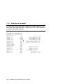
Show Boot Command...................................................................... 7-7
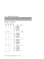
Show Config Command................................................................... 7-8
Show Device Command ................................................................ 7-16
Show Memory Command .............................................................. 7-18
Setting SRM Environment Variables ................................................. 7-19
Setting SRM Console Security ............................................................ 7-20
Setting Tru64 UNIX or OpenVMS Systems to Auto Start ........... 7-21
Changing the Default Boot Device...................................................... 7-21
Soft Partitioning.................................................................................. 7-22
Hard Partitioning................................................................................ 7-26
Chapter 8
8.1
8.2
8.3
8.3.1
8.4
8.5
8.6
8.7
8.7.1
8.7.2
8.7.3
8.7.4
8.7.5
8.7.6
8.7.7
8.8
Using the System Control Manager
Console Serial Bus Subsystem.............................................................. 8-2
System Control Manager Overview ...................................................... 8-4
SCM COM1 Operating Modes............................................................... 8-6
Bypass Modes ................................................................................. 8-8
Console Device Setup .......................................................................... 8-10
Entering the SCM ............................................................................... 8-12
SRM Environment Variables for COM1 ............................................. 8-13
SCM Command-Line Interface ........................................................... 8-14
Defining the COM1 Data Flow ..................................................... 8-17
Displaying the System Status ...................................................... 8-18
Displaying the System Environment............................................ 8-20
Power On and Off, Reset, and Halt .............................................. 8-22
Configuring Remote Dial-In ......................................................... 8-24
Configuring Alert Dial-Out........................................................... 8-26
Resetting the Escape Sequence .................................................... 8-29
Troubleshooting Tips .......................................................................... 8-30
Appendix A
A.1
A.2
A.3
Operation
Jumpering Information
PCI Backplane Jumpers .......................................................................A-1
HPM Jumpers .......................................................................................A-2
Standard I/O Module Jumpers..............................................................A-2
v
Glossary
Index
Examples
6–1
6–2
6–3
6–4
6–5
6–6
6–7
6–8
7–1
7–2
7–3
7–4
7–5
7–6
7–7
8–1
8–2
SCM Power-Up Display ........................................................................ 6-2
SRM Power-Up Display ........................................................................ 6-6
Booting Tru64 UNIX from a Local SCSI Disk .................................... 6-16
RIS Boot .............................................................................................. 6-18
Tru64 UNIX Installation Display ....................................................... 6-20
Booting OpenVMS from a Local Disk ................................................. 6-22
InfoServer Boot ................................................................................... 6-24
OpenVMS Installation Menu .............................................................. 6-26
Set Ocp_Text Command...................................................................... 7-6
Show Boot*............................................................................................ 7-7
Show Config .......................................................................................... 7-8
Show Device ........................................................................................ 7-16
Show Memory...................................................................................... 7-18
Defining Soft Partitions ...................................................................... 7-24
Defining Hard Partitions .................................................................... 7-26
Dial-In Configuration.......................................................................... 8-24
Alert Dial-Out Configuration .............................................................. 8-26
Figures
1–1
1–2
2–1
2–2
2–3
2–4
2–5
2–6
2–7
2–8
2–9
2–10
2–11
2–12
2–13
vi
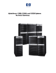
AlphaServer GS160 and GS80 Systems................................................ 1-2
Sample System Architecture................................................................. 1-5
System Box............................................................................................ 2-2
System Box Block Diagram (16-Processor System) .............................. 2-4
System Box Block Diagram (8-Processor System) ................................ 2-5
System Box QBBs (Top View) ............................................................... 2-6
Backplane (System Box, Front View) ................................................... 2-8
CPU Module ........................................................................................ 2-10
Memory Module .................................................................................. 2-11
Directory Module................................................................................. 2-12
Power Modules .................................................................................... 2-13
Power System Manager Module ......................................................... 2-14
Clock Splitter Module ......................................................................... 2-15
I/O Riser Module ................................................................................. 2-16
Global Port Module ............................................................................. 2-17
2–14
2–15
2–16
2–17
2–18
2–19
2–20
2–21
3–1
3–2
3–3
3–4
3–5
3–6
3–7
3–8
3–9
3–10
3–11
3–12
4–1
4–2
4–3
4–4
5–1
5–2
8–1
8–2
8–3
8–4
Distribution Board .............................................................................. 2-18
Distribution Board in Single-Box System........................................... 2-19
Hierarchical Switch............................................................................. 2-20
Power System...................................................................................... 2-22
AC Input Box ...................................................................................... 2-24
PCI Master Box................................................................................... 2-26
Control Panel ...................................................................................... 2-28
Control Panel LED Status .................................................................. 2-30
GS160 System ....................................................................................... 3-2
GS320 System ....................................................................................... 3-4
Power Cabinet Configuration (32-P System) ........................................ 3-6
Power Supply Slot Assignments ........................................................... 3-8
System Box QBB (Cabinet Front) ....................................................... 3-10
System Box QBB (Cabinet Rear) ........................................................ 3-11
QBB Center Bar Color Code (Cabinet Front) ..................................... 3-12
QBB Center Bar Color Code (Cabinet Rear)....................................... 3-13
Memory Module and Directory Module .............................................. 3-14
Sample I/O Subsystem ........................................................................ 3-18
PCI Slot Locations............................................................................... 3-20
BA356 Storage Device Configurations................................................ 3-22
System Drawer...................................................................................... 4-2
Two-Drawer Block Diagram ................................................................. 4-4
System Drawer Modules ....................................................................... 4-6
System Drawer Backplane.................................................................... 4-7
Rack....................................................................................................... 5-2
Two-Drawer Rack Power System.......................................................... 5-4
CSB Block Diagram .............................................................................. 8-2
Data Flow in Through Mode ................................................................. 8-6
Data Flow in Bypass Mode ................................................................... 8-8
Setups for SCM (PCI Box).................................................................. 8-11
Tables
1
2–1
2–2
2–3
3–1
3–2
4–1
4–2
6–1
AlphaServer 80/160/320 Family Documentation .................................. xiv
System Box Characteristics .................................................................. 2-2
Power Cabinet and System Environmental Characteristics ................ 2-3
AC Input Box Circuit Breakers........................................................... 2-25
Interleaving Memory Modules ............................................................ 3-16
PCI Slots and Logical Hoses ............................................................... 3-21
System Drawer Characteristics ............................................................ 4-2
Rack System Characteristics ................................................................ 4-3
OpenVMS Boot Flag Settings ............................................................. 6-13
vii
7–1
7–2
7–3
7–4
7–5
7–6
8–1
8–2
8–3
8–4
A–1
A–2
A–3
viii
Summary of SRM Commands ............................................................... 7-2
Notation Formats for SRM Console Commands ................................... 7-4
Special Characters for SRM Console ................................................... 7-5
Device Naming Conventions ............................................................... 7-17
SRM Environment Variables for Soft Partitions ................................ 7-23
SCM Environment Variables for Hard Partitions .............................. 7-26
SCM Commands.................................................................................. 8-14
Status Command Fields...................................................................... 8-18
Elements of Dial String and Alert String ........................................... 8-28
SCM Troubleshooting.......................................................................... 8-30
PCI Backplane Jumpers .......................................................................A-1
HPM Jumpers .......................................................................................A-2
Standard I/O Module Jumpers..............................................................A-2
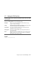
Preface
Intended Audience
This manual is for managers and operators of Compaq AlphaServer 80/160/320
family systems.
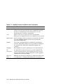
Document Structure
This manual uses a structured documentation design. Topics are organized into
small sections, usually consisting of two facing pages. Most topics begin with an
abstract that provides an overview of the section, followed by an illustration or
example. The facing page contains descriptions, procedures, and syntax
definitions.
This manual has eight chapters, an appendix, and glossary.
•
Chapter 1, Introduction, gives a general overview of the AlphaServer
80/160/320 family.
•
Chapter 2, GS320 System Overview, describes the components of the
GS320 system.
•
Chapter 3, GS320 System Configuration Rules, provides configuration
guidelines for the GS320 system.
•
Chapter 4, GS80 Rack System Overview, describes the components of
the GS80 rack system.
•
Chapter 5, GS80 Rack System Configuration Rules, provides
configuration guidelines for the GS80 system.
•
Chapter 6, Booting and Installing an Operating System, tells how to
boot a supported operating system and how to set boot options.
•
Chapter 7, Operation, gives basic operating instructions.
•
Chapter 8, Using the System Control Manager, describes the function
and operation of the system control manager.
ix
•
Appendix A, Jumpering Information, calls out jumpers and their
functions.
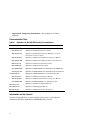
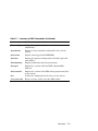
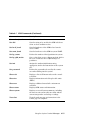
Documentation Titles
Table 1 AlphaServer 80/160/320 Family Documentation
Order Number
Title
QA–6GAAA–G8
AlphaServer GS80/160/320 Documentation Kit
EK–GS320–UG
AlphaServer GS80/160/320 User’s Guide
EK–GSCON–IN
AlphaServer GS80/160/320 System Management Console
Installation and User’s Guide
EK–GS320–RM
AlphaServer GS80/160/320 Firmware Reference Manual
EK–GSPAR–RM
AlphaServer GS80/160/320 Getting Started with Partitions
EK–GS320–IN
AlphaServer GS160/320 Installation Guide
EK–GSR80–IN
AlphaServer GS80 Installation Guide
AG–RKSWB–BE
AlphaServer GS80/160/320 User Information CD (HTML files)
AG–RLVJA–BE
AlphaServer GS80/160/320 User Information CD (translations)
QA–6GAAB–G8
AlphaServer GS80/160/320 Service Documentation Kit
EK–GS320–SV
AlphaServer GS80/160/320 Service Manual
EK–GS320–RM
AlphaServer GS80/160/320 Firmware Reference Manual
AG–RKSZA–BE
AlphaServer GS80/160/320 Service Information CD
EK–GS320–UP
AlphaServer GS160/320 Upgrade Manual
EK–GSR80–UP
AlphaServer GS80 Upgrade Manual
EK–GS320–SP
AlphaServer GS80/160/320 Site Preparation
Information on the Internet
Visit the Compaq Web site at www.compaq.com for service tools and more
information about the AlphaServer 80/160/320 family systems.
x
Chapter 1
Introduction
The Compaq AlphaServer GS160/320 and GS80 systems are high-performance
server platforms designed for enterprise-level applications. They offer a high
degree of scalability and expandability.
The GS160/320 system uses up to four Alpha microprocessors in each quad
building block (QBB). Two QBBs are paired back-to-back and rotated 180
degrees with reference to each other and then enclosed in a system box. A
system cabinet can hold up to two system boxes.
The GS80 rack system uses up to four Alpha microprocessors in a drawer. Each
rack holds up to two system drawers.
This chapter introduces the AlphaServer GS160/320 and AlphaServer GS80
systems. There are three sections:
•
AlphaServer GS160/320 and GS80 Systems
•
Firmware and Utilities Overview
•
System Architecture
NOTE: When you unpack your system, be sure to save and store all shipping
brackets, pallets, and packing material. You will need this material to
repack the system, if you should decide to relocate it.
Introduction
1-1
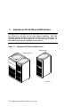
1.1
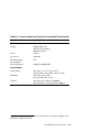
AlphaServer GS160/320 and GS80 Systems
The AlphaServer GS160/320 system and GS80 rack system are separate,
but related, in that they use the same switch technology. The CPU
modules, memory modules, and power modules are also the same. In
the GS160/320 system, the modules are in a system box in a cabinet. In
the GS80 rack system, the modules are in a drawer.
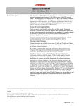
Figure 1–1 AlphaServer GS160 and GS80 Systems
GS80 System
GS160 System
PK-0654-00
1-2
AlphaServer GS80/160/320 User’s Guide
AlphaServer GS160/320 System
The AlphaServer GS160 system cabinet contains up to two system boxes
supporting a maximum of 16 CPU modules.
In an AlphaServer GS320 system, a second system cabinet is used to expand the
system (up to four system boxes containing a maximum of 32 CPU modules).
A power cabinet contains the power components, I/O boxes, and storage.
Additional I/O and storage can be housed in expander cabinets.
AlphaServer GS80 System
The AlphaServer GS80 rack system contains up to two system drawers, I/O, and
storage. Each system drawer supports up to four CPU modules, for a maximum
of eight CPUs per system. Power components are mounted at the bottom of the
rack cabinet.
An expander cabinet can be used to house additional I/O and storage.
System Management Console
The console device, called the system management console (SMC), is a Compaq
Deskpro PC, a DECserver 90M terminal server, and associated hardware and
software. For installation instructions and user information, see the
AlphaServer GS80/160/320 System Management Console Installation and
User’s Guide.
Introduction
1-3
1.2
Firmware and Utilities Overview
Firmware residing in ROM on CPU and other modules in the system
provides commands for booting the operating system, testing devices
and I/O adapters, and other tasks useful in operating and maintaining a
running system. You type commands at the console device.
SRM Console
Systems running the Tru64 UNIX or OpenVMS operating systems are
configured from the SRM console, a command-line interface (CLI). From the
CLI you can enter commands to configure the system, view the system
configuration, and boot the system.
System Control Manager (SCM)
The SCM firmware allows the user to access the system remotely. In addition,
the SCM:
•
Monitors and notifies the user of power or temperature alert conditions
•
Controls initial system power-up
•
Manages hard partitions
LFU (Loadable Firmware Update Utility)
You can boot this utility (with the SRM boot command) whenever you need to
update the SRM console firmware or I/O device firmware. The CD with the
AlphaServer firmware is updated periodically.
1-4
AlphaServer GS80/160/320 User’s Guide
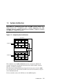
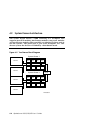
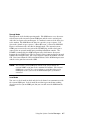
1.3
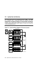
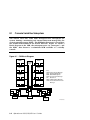
System Architecture
Each QBB in a GS160/320 system and each QBB (system drawer) in a
GS80 system has a backplane and a switch supporting the CPU
modules, memory modules, and I/O riser modules. Figure 1–2 shows
two QBBs in a single-box system.
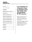
Figure 1–2 Sample System Architecture
System Box
CPU
To PCI Boxes
I/O
MEM
CPU
CPU
Switch
MEM
MEM
CPU
GP
MEM
Distribution
Board
CPU
To PCI Boxes
I/O
MEM
CPU
CPU
Switch
MEM
MEM
CPU
GP
MEM
PK-0601A-98
The backplane of each QBB (GS160/320 systems) and drawer (GS80 rack
systems) contains the switch that interconnects the CPU modules, memory
modules, and I/O riser modules.
The global port and distribution board provide the interconnect for the QBBs.
In a two-box system, a hierarchical switch is used as the interconnect, in place
of the distribution board.
I/O riser modules connect the PCI boxes to the QBB backplane.
Introduction
1-5
Chapter 2
GS160/320 System Overview
Each system cabinet contains one or two system boxes. The system box houses
two quad building blocks, or QBBs. CPU modules, memory modules, power
modules, and I/O riser modules plug into the QBB backplane.
The power cabinet contains power components, PCI boxes, and storage shelves.
This chapter provides an overview of the system in these sections:
•
System Characteristics
•
System Box Architecture
•
Quad Building Block (QBB) Components
•
Power System
•
PCI I/O
•
Control Panel
GS160/320 System Overview
2-1
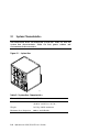
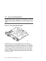
2.1
System Characteristics
The illustration shows the BA51A-AA system box. Table 2–1 lists the
system box characteristics. Table 2–2 lists power cabinet and
environmental characteristics.
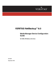
Figure 2–1 System Box
PK0611
Table 2–1 System Box Characteristics
Characteristic
Specification
Size
535 mm H x 550 mm W x 475 mm D
(21.06 in. x 21.65 in. x 18.7 in.)
Weight
54.55 kg (120 lb) maximum
Maximum heat dissipation
2000 w (6,850 Btu/hr)
2-2
AlphaServer GS80/160/320 User’s Guide
Table 2–2 Power Cabinet and System Environmental Characteristics
Power Cabinet
Specifications
Electrical
Voltage
120/208 VAC (U.S)
380–415 VAC (Europe)
200 VAC (Japan)
Phase
3-phase
Frequency
50–60 Hz
Maximum input
current/phase
21 A
Heat dissipation
1
9,300 W/31,800 Btu/Hr
Environmental
Temperature
Operating: 5° to 35°C (41 to 95°F)
Not operating: -40° to 66°C (-40° to 151°F)
Humidity
Operating: 10% to 90%
Not operating: 10% to 95%
Altitude
Operating: 0 to 3 km (0 to 10,000 ft)
Not operating: 0 to 12.2 km (0 to 40,000 ft)
1
A fully configured system with three system boxes, nine power supplies, two
PCI boxes, and storage shelf.
GS160/320 System Overview
2-3
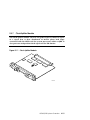
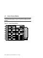
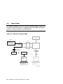
2.2
System Box Architecture
The system box houses two quad building blocks (QBBs). Each QBB
has a backplane with a switch interconnect that supports up to four
CPU modules, four memory modules, two power modules, two I/O riser
modules, and a global port. Figure 2–2 shows two system boxes
connected by the hierarchical switch. Figure 2–3 shows one system box
and the distribution board.
Figure 2–2 System Box Block Diagram (16-Processor System)
System Box 1
Modem
PCI Box
Standard
I/O SCM
CPU CPU CPU CPU
I/O
Switch
GP
MEM MEM MEM MEM
Operator
Console
PCI Box
CPU CPU CPU CPU
PCI Box
I/O
Switch
GP
MEM MEM MEM MEM
PCI Box
System Box 2
Hierarchical
Switch
CPU CPU CPU CPU
PCI Box
I/O
Switch
GP
MEM MEM MEM MEM
PCI Box
CPU CPU CPU CPU
PCI Box
I/O
Switch
GP
MEM MEM MEM MEM
PCI Box
PK-0623-98
2-4
AlphaServer GS80/160/320 User’s Guide
The switch on the backplane connects the CPU modules, memory modules, I/O
riser modules, and global port. In an 8-P system, the global ports connect the
QBBs to the distribution board. In a 16-P or a 32-P system, the global ports
connect the QBBs to the hierarchical switch.
Figure 2–3 System Box Block Diagram (8-Processor System)
Modem
System Box
PCI Box
Standard
I/O SCM
CPU
I/O
MEM
Operator
Console
CPU
CPU
Switch
MEM
MEM
CPU
GP
MEM
PCI Box
Distribution
Board
CPU
PCI Box
I/O
MEM
PCI Box
CPU
CPU
Switch
MEM
MEM
CPU
GP
MEM
PK-0601-98
GS160/320 System Overview
2-5
2.3
Quad Building Block (QBB) Components
Figure 2–4 shows two QBBs back to back in the system box.
Figure 2–4 System Box QBBs (Top View)
QBB 1 (Front)
2
1
Top View
4
1
2
QBB 0 (Rear)
2-6
AlphaServer GS80/160/320 User’s Guide
3
PK-0612-98
The QBB backplanes are attached to a stiffener and mounted in a system box
enclosure. Each backplane has a differently positioned cutout to accommodate
the global port modules. A global port module is mounted on the front of one
QBB and the other is mounted on the back of the other QBB, putting both
global port modules near the distribution board (or the hierarchical switch)
when the system box is installed in the cabinet.
The callouts in Figure 2–4 point to the location of these components in the
system box:
➊
I/O riser module area. Each QBB supports up to two I/O riser
modules.
➋
CPU module and memory module area. Each QBB holds four CPUs
and four memory modules.
➌
➍
Global port area.
Backplane area.
GS160/320 System Overview
2-7
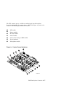
2.3.1
Backplane
Each QBB backplane is located at the center of the system box. Figure
2–5 shows an unpopulated backplane (no modules installed) as you
would see it from the front of the system box.
Figure 2–5 Backplane (System Box, Front View)
1
2
3
4
3
6
4
3
4
4
3
5
7
8
9
PK0600
2-8
AlphaServer GS80/160/320 User’s Guide
The CPU, memory, power, and I/O riser modules plug into the backplane.
Because of the orientation of the QBB backplanes, the modules are situated
differently in the front and rear of the system box. See Section 3.5 for more
information.
The switch interconnect on the backplane allows any processor to access any
memory on the QBB. The backplane also provides power to the modules.
➊
➋
➌
➍
➎
➏
➐
➑
➒
Global port module
Directory module
CPU module
Memory module
I/O riser modules
Clock splitter module
Power system manager (PSM) module
Main power module
Auxiliary power module
GS160/320 System Overview
2-9
2.3.2
CPU Module
A CPU module comes with an Alpha microprocessor chip with a Bcache, cache control and TAG comparison logic, clock logic, and a DCDC power converter.
Also included on the module is logic for
implementing self-test diagnostics. Each module has a Run LED and a
Hot Swap LED.
Figure 2–6 CPU Module
Power
Converter
CPU
Chip
Run LED
Hot Swap
LED
PK0602
2-10
AlphaServer GS80/160/320 User’s Guide
2.3.3
Memory Module
A memory module has eight DIMM slots. See Section 3.7 for memory
configuration guidelines.
Figure 2–7 Memory Module
DIMMs
PK0603
GS160/320 System Overview
2-11
2.3.4
Directory Module
In a GS160/320 system, one directory module is required for each QBB
in a system box. In a two-drawer GS80 system, a directory module is
required in each system drawer. No directory module is needed in a
one-drawer system. The directory module functions as a memory
coherency manager.
Figure 2–8 Directory Module
Directory
DIMMs
PK0606
2-12
AlphaServer GS80/160/320 User’s Guide
2.3.5
Power Modules
Two power modules are installed in the QBB backplane. The main
power module and the auxiliary power module convert 48 VDC to the
various voltages required to power the QBB.
Figure 2–9 Power Modules
Auxiliary Power Module
Main Power Module
PK-0604-99
GS160/320 System Overview
2-13
2.3.6
Power System Manager Module
Each QBB has one power system manager (PSM) module. This module
monitors CPUs, voltages, temperatures, and blower speed in the
cabinet and reports this information to the system control manager
(SCM).
Figure 2–10 Power System Manager Module
PK0607
The PSM module is connected to other PSM modules and the SCM microprocessor (located on the standard I/O module) through the console serial bus
(CSB). The SCM is the master; the PSM can only operate as a slave. The PSM
controls the powering on/off and resetting of all modules within the QBB and of
2
the QBB itself. The PSM also contains three I C bus interfaces and a serial I/O
bus channel to each CPU in the QBB. The PSM module retrieves information
2
from the I C EEROMs residing on the CPUs, memory modules, and the QBB
backplane. The PSM uses a serial I/O port connection to communicate with one
CPU module at a time. The PSM can only perform a function as the result of a
request from the SCM.
2-14
AlphaServer GS80/160/320 User’s Guide
2.3.7
Clock Splitter Module
The clock splitter module converts one global signal to identical copies
of a signal that is then distributed to master phase lock loops
associated with the ASICs and the system processors within a QBB. It
also generates independent clock signals for the I/O domain.
Figure 2–11 Clock Splitter Module
PK2222
GS160/320 System Overview
2-15
2.3.8
I/O Riser Module
The I/O riser module is used to connect the QBB backplane to a PCI
box. A “local” I/O riser module is located on the QBB backplane; a
“remote” I/O riser module is in the PCI box.
Figure 2–12 I/O Riser Module
PK0605
2-16
AlphaServer GS80/160/320 User’s Guide
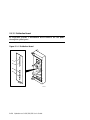
2.3.9
Global Port Module
The global port provides the interconnect to the other QBB(s) through
the distribution board or the hierarchical switch.
Figure 2–13 Global Port Module
Front QBB
Rear QBB
PK-0655-00
GS160/320 System Overview
2-17
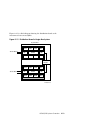
2.3.10 Distribution Board
In single-box systems, a distribution board connects the two QBBs
through the global ports.
Figure 2–14 Distribution Board
A1
B1
B0
A0
PK1244
2-18
AlphaServer GS80/160/320 User’s Guide
Figure 2–15 is a block diagram showing the distribution board as the
interconnect between two QBBs.
Figure 2–15 Distribution Board in Single-Box System
System Box
CPU
To PCI Boxes
I/O
MEM
CPU
CPU
Switch
MEM
MEM
CPU
GP
MEM
Distribution
Board
CPU
To PCI Boxes
I/O
MEM
CPU
CPU
Switch
MEM
MEM
CPU
GP
MEM
PK-0601A-98
GS160/320 System Overview
2-19
2.3.11 Hierarchical Switch
In two-box systems, a hierarchical switch links the QBBs through the
global ports. The hierarchical switch connects QBBs in three- and
four-box systems also.
Figure 2–16 Hierarchical Switch
System
Box 2
System
Box 4
System
Box 3
System
Box 1
PK0626
2-20
AlphaServer GS80/160/320 User’s Guide
The hierarchical switch links the QBBs in systems having more than one
system box. Figure 2–16 shows cable connectors for each system box (a pair of
connectors for two signal cables routed to each QBB global port in the system).
The hierarchical switch power manager (HPM) module controls power and
monitors the temperature inside the hierarchical switch housing. The HPM
module, along with the PSM modules and PBM modules, report status
information to the SCM.
GS160/320 System Overview
2-21
2.4
Power System
Each system box has a power subrack with up to three 48 VDC power
supplies. Figure 2–17 shows the power system for a 32-P system. See
Section 3.3 for power configuration rules.
Figure 2–17 Power System
System
Box 4
(Brown)
System
Box 2
(Green)
Subrack 1
(Blue)
System
Box 3
(Orange)
Subrack 2
(Green)
System
Box 1
(Blue)
Subrack 3
(Orange)
Subrack 4
(Brown)
AC Input
Orange
Brown
Blue
Green
2
AC Input
1
PK0615A
2-22
AlphaServer GS80/160/320 User’s Guide
Power cables and components are color-coded to ensure proper identification
and easy handling.
NOTE: Color-coded components and power cables must match to ensure proper
power distribution, particularly in hard-partitioned systems.
Figure 2–17 shows each system box and its color-related power subrack and AC
input box. The AC input box also has color-coded circuit breakers. Each AC
input box provides power to the subracks, PCI boxes, and storage shelves.
Power distribution and signal cables are connected from the power subrack to
the QBB backplanes through a power distribution bulkhead. Another cable is
used to provide power to the blower, located at the bottom of the system cabinet,
and the control panel, located in the power cabinet.
Each QBB has its own main power module and auxiliary power module. Each
CPU module has its own power converter that converts the 48 VDC to the
required voltage.
When the main power circuit breaker (CB1) is on and the AC input box is
plugged in, the console serial bus (CSB) has auxiliary power (Vaux), enabling
the system control manager (SCM) to power up the system.
See Section 2.4.1 for more information on the AC input box and circuit breakers.
GS160/320 System Overview
2-23
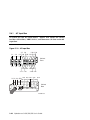
2.4.1
AC Input Box
A system has two AC input boxes. Figure 2–18 shows the circuit
breakers (CB1–CB11), LEDs (L1–L3), and connectors (J1–J22) on the AC
input box.
Figure 2–18 AC Input Box
J-7 J-9
J-1
J-2
J-16 J-18
J-8 J-10 J-15 J-17
J-3
Cabinet
Front
J-4
J-5
J-6
J-12 J-14 J-19 J-21
J-11 J-13
L1 L2 L3 CB1
J-20 J-22
CB3 CB5 CB7 CB9
CB11
CB2 CB4 CB6 CB8 CB10
Cabinet
Rear
PK-0645-99
2-24
AlphaServer GS80/160/320 User’s Guide
The three LEDs on the AC input box should be lit at all times, indicating that
all three power phases are present in the 3-phase AC input.
Table 2–3 lists the AC input box circuit breakers and the lines they protect.
Table 2–3 AC Input Box Circuit Breakers
Circuit Breaker
Line(s) Protected
CB1 (Main)
All lines protected.
CB2
J1
CB3
J2
CB4
J3
CB5
J4
CB6
J5
CB7
J6
CB8
J7, J8, J9, J10
CB9
J11, J12, J13, J14
CB10
J15, J16, J17, J18
CB11
J19, J20, J21, J22
GS160/320 System Overview
2-25
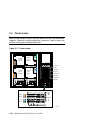
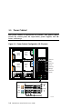
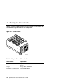
2.5
PCI I/O
The power cabinet contains at least one PCI master box, and may
contain PCI expansion boxes.
Figure 2–19 PCI Master Box
Front
Keyboard
DVD/CD-ROM
Floppy Drive
Power Supply LEDs
Mouse
COM 2 Operator
Serial Port Control Parallel
Panel Port
Power Supply LEDs
Rear
Remote I/O
Riser Module
Remote I/O Local Terminal
Riser Module
Port
LEDs
CSB Node
ID Switch
CSB
USB Modem
Ports Port
2-26
AlphaServer GS80/160/320 User’s Guide
PK0656
A PCI master box has a standard I/O module, a DVD/CD-ROM drive and a
floppy drive as shown in Figure 2–19. PCI expansion boxes provide additional
slots for options. Each PCI power supply has three LEDs: Vaux OK, Power OK,
and Swap OK.
BA54A-AA PCI Box
The BA54A-AA PCI box is a PCI master box. It contains the following
components:
•
Backplane with a standard I/O module
•
Thirteen I/O option slots
•
DVD/CD-ROM drive
•
SCSI disk drive
•
Floppy drive
•
Ports: one local terminal port, one serial port, one modem port, one parallel
port, two USB ports, one keyboard port, one mouse port, one CSB port, and
one control panel port
•
Two I/O riser slots
•
Two power supplies
BA54A-BA PCI Box
The BA54A-BA box is a PCI expansion box and contains the following
components:
•
Backplane with fourteen option slots
•
Two I/O riser slots
•
Two power supplies
GS160/320 System Overview
2-27
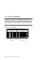
2.6
Control Panel
The control panel is located at the top of the power cabinet. It has a
three-position Off/On/Secure switch, three pushbuttons, three status
LEDs, and a diagnostic display.
Figure 2–20 Control Panel
1
2
3
8
4
5
9
10
6
7
PK0621
2-28
AlphaServer GS80/160/320 User’s Guide
The callouts in Figure 2–20 point to these components on the control panel:
➊
Secure LED – When lit, indicates that the keyswitch is in the Secure
position and system is powered on. All pushbuttons and SCM functions
are disabled, including remote access to the system.
➋
Power OK LED – When lit, indicates at least one QBB is powered on and
remote console operations are enabled. The keyswitch is in the On
position.
➌
Halt LED – When lit with the Power LED, indicates the system is powered
on, remote console operations are enabled, and the Halt pushbutton is
pressed.
When lit with both Power LED and Secure LED, indicates a powered on
system, disabled remote console operations, and Halt pushbutton is
pressed in.
➍
➎
Diagnostic display indicates system status.
➏
On switch position – System is enabled to be powered up. A remote system
user can power on or power off the system.
➐
Secure switch position – System is powered on and cannot be remotely
powered on or off. All pushbuttons and SCM functions are disabled.
➑
Halt pushbutton – Pressing this pushbutton causes the operating system
to perform a halt, with no captured error information. The system will
automatically reset if the auto_fault_reset environment variable is
enabled.
➒
Fault pushbutton – Pressing this pushbutton causes a system reset
without clearing captured error information in the control and status
registers.
➓
Reset pushbutton – Pressing this pushbutton causes a system reset that
clears captured error information.
Off switch position – System is powered off and cannot be powered on
remotely.
GS160/320 System Overview
2-29
2.6.1
Control Panel LEDs
Figure 2–21 shows the various control panel LED status indications.
Figure 2–21 Control Panel LED Status
Control Panel LEDs
Secure
Power
OK
Status
Halt
System powered on; remote console disabled; pause mode.
System powered on; remote console disabled.
System powered on; remote console enabled; remote console
halt or Halt button depressed.
System powered on; remote console enabled.
System powered off for any of the following reasons:
o No AC power available
o Keyswitch in Off position
o Keyswitch in On position but system powered off by remote
console or power/temperature failure
On
Off
PK-0622-99
2-30
AlphaServer GS80/160/320 User’s Guide
Chapter 3
GS160/320 System Configuration Rules
This chapter provides configuration rules for the following:
•
GS160 System Cabinet
•
GS320 System Cabinets
•
Power Cabinet
•
System Box
•
QBB Color Code
•
Memory Configurations
•
Memory Interleaving Guidelines
•
PCI Boxes
•
PCI Box Slot Configuration
•
Expander Cabinet
GS160/320 System Configuration Rules
3-1
3.1
GS160 System Cabinet
Figure 3–1 shows the front view of the system cabinet and the power
cabinet. One system cabinet houses either one system box or two
system boxes. In a one-box system, a distribution board connects the
two QBBs. In a two-box system, a hierarchical switch connects the
QBBs.
Figure 3–1 GS160 System
System
Box 2
System
Box 1
PK0614
3-2 AlphaServer GS80/160/320 User’s Guide
About the System Cabinet
The cabinet contains the following components:
•
Vertical mounting rails
•
Wrist strap for static discharge protection
GS160 Configuration Rules
•
System box 1 (see Figure 3–1) is mounted in the lower half of the cabinet,
above the blower.
•
System box 2 is mounted in the upper half of the cabinet, over system box 1.
GS160/320 System Configuration Rules
3-3
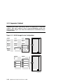
3.2
GS320 System Cabinets
Figure 3–2 shows the front view of the system cabinets. Two system
cabinets house either three system boxes or four system boxes. A
hierarchical switch is used to connect the QBBs.
Figure 3–2 GS320 System
System
Box 4
System
Box 2
System
Box 3
System
Box 1
PK0615
3-4 AlphaServer GS80/160/320 User’s Guide
GS320 System Configuration Rules
•
In system cabinet 1, system box 1 (see Figure 3–2) is mounted in the lower
half of the cabinet, above the blower. System box 2 is mounted in the upper
half of the cabinet, above system box 1.
•
In system cabinet 2, system box 3 is mounted in the lower half of the
cabinet; system box 4, the upper half of the cabinet.
GS160/320 System Configuration Rules
3-5
3.3
Power Cabinet
One power cabinet is required for all systems. The power cabinet
houses the control panel, AC input boxes, power supplies, PCI I/O
boxes, and storage.
Figure 3–3 Power Cabinet Configuration (32-P System)
System
Box 4
(Brown)
System
Box 2
(Green)
Subrack 1
(Blue)
System
Box 3
(Orange)
Subrack 2
(Green)
System
Box 1
(Blue)
Subrack 3
(Orange)
Subrack 4
(Brown)
AC Input
Orange
Brown
Blue
Green
2
AC Input
1
PK0615A
3-6 AlphaServer GS80/160/320 User’s Guide
Power System Requirements
•
Each system box requires a power subrack.
•
Each power subrack has three power supplies. The third power supply is
always redundant. See Section 3.3.1 for power supply slot assignments.
•
Two AC input boxes are required.
Cables, AC input boxes (including AC circuit breakers), power subracks, and
system boxes are color-coded at cable connections to ensure proper cabling.
Figure 3–3 shows the color coding scheme for a 32-P system.
PCI boxes and storage shelves are installed in the upper half of the power
cabinet.
GS160/320 System Configuration Rules
3-7
3.3.1
Power Supply Slot Assignments
Figure 3–4 show the power supply slot assignments in each power
subrack.
Figure 3–4 Power Supply Slot Assignments
Power
Cabinet
Bulkhead
Blue
Power
Subrack
R
1
1
2
3
Green
Power
Subrack
R
2
1
2
3
Power
Cabinet
Bulkhead
Orange
Power
Subrack
R
3
1
2
3
Brown
Power
Subrack
R
4
1
2
3
AC Input 2
AC Input 1
R indicates redundant power supply slot.
PK-0624-99
3-8 AlphaServer GS80/160/320 User’s Guide
Power Supply Configuration Rules
•
Power subracks are always mounted in the same power cabinet location,
regardless of the number of system boxes.
•
Power supply slot assignments remain the same in all systems, regardless
of the number of system boxes.
•
A redundant power supply slot is always the last slot to be used in a
subrack.
GS160/320 System Configuration Rules
3-9
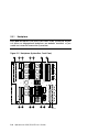
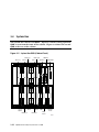
3.4
System Box
The system box contains two QBBs. Figure 3–5 shows a fully populated
QBB as seen from the front of the cabinet. Figure 3–6 shows the second
QBB at the rear of the cabinet.
Figure 3–5 System Box QBB (Cabinet Front)
Memory 2
Directory
CPU 3
Clock
Splitter
Memory 3
Memory 0
CPU 1
CPU 2
I/O Riser
I/O Riser
CPU 0 PSM
Memory 1
Main
Power
Signal Cable
Auxiliary
Power
PK0610
3-10
AlphaServer GS80/160/320 User’s Guide
System Box Configuration Rules
•
A system box has two QBBs.
•
A QBB supports up to four CPU modules.
•
A QBB supports up to four memory modules.
•
A QBB has up to two I/O riser modules; each I/O riser module connects to
one PCI box.
•
A system box supports up to four PCI boxes.
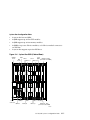
Figure 3–6 System Box QBB (Cabinet Rear)
Auxiliary
Power
Power
Connectors
PSM
Main
Power
I/O Riser
I/O Riser
Memory 1
Clock
Splitter Global Port - Odd
(Connected to front QBB)
Memory 3
CPU 1
CPU 3
CPU 0
Memory 0
CPU 2
Memory 2
Directory
Global Port - Even
(Connected to back QBB)
PK2228
GS160/320 System Configuration Rules
3-11
3.5
QBB Color Code
Figure 3–7 and Figure 3–8 show the center bar color code for module
placement in the QBB. Note that CPU and memory slots are colorcoded to ensure the correct placement of each module.
Figure 3–7 QBB Center Bar Color Code (Cabinet Front)
CPU 3
(Blue)
Directory
(White)
Memory 3
(Gray)
Clock
Splitter
(Green)
CPU 1
(Blue)
Memory 2
(Gray)
Memory 1
(Gray)
CPU 2
(Blue)
Memory 0
(Gray)
PSM
(Orange)
CPU 0
(Blue)
Auxiliary
Power
(Red)
Main
Power
(Yellow)
PK0628
3-12
AlphaServer GS80/160/320 User’s Guide
Figure 3–8 QBB Center Bar Color Code (Cabinet Rear)
Main
Power
(Yellow)
Auxiliary
Power
(Red)
CPU 0
(Blue)
PSM
(Orange)
Memory 0
(Gray)
CPU 2
(Blue)
Clock
Splitter
(Green)
Memory 1
(Gray)
Memory 2
(Gray)
CPU 1
(Blue)
CPU 3
(Blue)
Memory 3
(Gray)
Global
Port 1
Global
Port 0
Directory
(White)
PK2229
GS160/320 System Configuration Rules
3-13
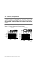
3.6
Memory Configurations
A memory module has eight DIMM slots. Two arrays (Array 0 and
Array 1), consisting of four DIMMs, can be installed on each module. A
directory DIMM is required for each array in systems having more than
four processors. Directory DIMMs are installed on the directory
module.
Figure 3–9 Memory Module and Directory Module
Memory Module
DIMM 0
DIMM 1
DIMM 2
DIMM 3
DIMM 0
DIMM 1
Array 1
DIMM 2
DIMM 3
Array 0
Directory Module
DIMM 0
DIMM 1
DIMM 2
DIMM 3
DIMM 4
DIMM 5
DIMM 6
DIMM 7
PK-0651-99
3-14
AlphaServer GS80/160/320 User’s Guide
Memory Configuration Guidelines
•
On a memory module, DIMMs are divided into two groups of four called
arrays.
•
A memory module must be populated on an array-by-array basis; that is,
groups of four DIMMs must be installed.
•
DIMMs in an array must be the same size and type.
•
DIMM sizes include 256 Mbyte, 512 Mbyte, and 1 Gbyte.
There are two types of DIMMs: single density (SD) and double density (DD).
•
Density does not affect interleaving.
•
One directory module DIMM is required for each memory array in systems
with more than one QBB.
•
The type and number of DIMMs installed in the directory module is based
on the number of memory arrays populated and the physical size of the
memory arrays. See the table below.
•
A larger DIMM type may always be used in place of the minimum required
DIMM type.
Directory DIMM Type
Memory Array Size
Part Number
0
256 MB
54-25019-AA
1
1 GB
54-25023-AA
2
2 GB
54-25023-BA
3
2 GB
54-25023-CA
4
4 GB
54-25023-DA
GS160/320 System Configuration Rules
3-15
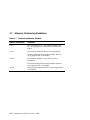
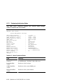
3.7
Memory Interleaving Guidelines
Table 3–1 Interleaving Memory Modules
Memory Interleaving
Guidelines
4-way
The default interleave. One memory module with
one array populated (or most mixes not discussed
below).
8-way
One memory module with two arrays populated.
Preferred method: Two memory modules with one
array populated on each module.
16-way
Two memory modules, each with two arrays
populated.
Preferred method. Four memory modules with one
array populated on each module.
32-way
3-16
Four memory modules with two arrays populated on
each module.
AlphaServer GS80/160/320 User’s Guide
Memory Interleaving Guidelines
•
The larger the interleaving factor, the better the system performance.
•
Avoid mixing memory sizes; this limits interleaving capability and
potential bandwidth.
GS160/320 System Configuration Rules
3-17
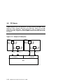
3.8
PCI Boxes
A QBB supports up to two PCI boxes. A cable connects the QBB “local”
I/O riser to the “remote” I/O riser in the PCI box. There are two I/O
ports on a local I/O riser. Each I/O port is used to connect to one
remote I/O riser. Figure 3–10 shows QBB0 connected to PCI box 0 and
PCI box 1.
Figure 3–10 Sample I/O Subsystem
PCI Box 0
PCI Box 1
PCA
Chip
PCI Bus
PCI Bus
PCI Bus
PCA
Chip
PCI Bus
PCA
Chip
PCI Bus
Remote I/O
Riser 1
PCA
Chip
PCI Bus
PCI Bus
Remote I/O
Riser 0
Remote I/O
Riser 1
1
0
Local I/O Riser
PCI Bus
Remote I/O
Riser 0
3
2
Local I/O Riser
QBB0
PK-0652-99
3-18
AlphaServer GS80/160/320 User’s Guide
The I/O subsystem consists of the local I/O interface (QBB) and the remote I/O
interface (PCI box) connected by I/O cables.
A system can have up to 16 PCI boxes. To identify PCI boxes in a system, a
node ID is set using the node ID switch located on the rear panel of each PCI
box (see Figure 3–11).
GS160/320 System Configuration Rules
3-19
3.9
PCI Box Slot Configuration
Each QBB can have two I/O risers supporting up to two PCI boxes. A
cable connects a local I/O riser (in the QBB) to a remote I/O riser (in the
PCI box). Each PCI box can have up to two remote I/O risers in place.
Cable connectors for the two remote I/O risers are shown as Riser 0 and
Riser 1 in Figure 3–11. PCI slots and logical hoses are listed in Table 3–
2.
Figure 3–11 PCI Slot Locations
Slot
7
6
5
4
3
2
1
7
6
Riser 1
5
4
3
2
1
Riser 0
PK-0643-99
3-20
AlphaServer GS80/160/320 User’s Guide
PCI Slot Configuration Guidelines
•
I/O riser 0 must be installed.
•
The standard I/O module is always installed in riser 0-slot 1.
•
Install high-powered modules in slots with one inch module pitch (all slots
except riser 0-slot 5, riser 0-slot 6, riser 1-slot 5, and riser 1-slot 6).
•
Install high-performance adapters across multiple bus/hose segments to get
maximum performance.
•
VGA graphics options must be installed in riser 0-slot 2 or riser 0-slot 3.
CAUTION:
Installing a full-length module next to the standard I/O module
requires extra care due to cabling on the standard I/O module.
Logical Hoses
You can have a maximum of four logical hoses per PCI box. Logical hose
numbers are assigned by the firmware. Logical hoses are numbered from 0 to
63.
Table 3–2 PCI Slots and Logical Hoses
Remote I/O Riser 0
Remote I/O Riser 1
Logical Hose 0
Logical Hose 1
Logical Hose 2
Logical Hose 3
Riser 0-Slot 1
Riser 0-Slot 4
Riser 1-Slot 1
Riser 1-Slot 4
Riser 0-Slot 2
Riser 0-Slot 5
Riser 1-Slot 2
Riser 1-Slot 5
Riser 0-Slot 3
Riser 0-Slot 6
Riser 1-Slot 3
Riser 1-Slot 6
---
Riser 0-Slot 7
---
Riser 1-Slot 7
GS160/320 System Configuration Rules
3-21
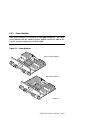
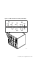
3.10 Expander Cabinet
Additional PCI boxes and storage devices are housed in an expander
cabinet. The same cabinet is used to expand GS160/320 systems and
GS80 systems. Figure 3–12 shows five different PCI and BA356 storage
configurations.
Figure 3–12 BA356 Storage Device Configurations
BA356
BA356(1)
(1)
BA356 (1)
BA356 (1)
BA356
BA356(2)
(2)
BA356 (2)
BA356 (2)
BA356
BA356(3)
(3)
BA356 (3)
BA356 (3)
BA356
BA356(4)
(4)
BA356 (4)
BA356 (4)
BA356 (5)
BA54A PCI (1)
BA356 (5)
BA54A PCI (1)
BA356 (6)
BA54A PCI (2)
BA356 (7)
BA54A PCI (1)
Default
Configuration
BA54A PCI (2)
Default
Configuration
BA356 (8)
BA356 (1)
BA356 (1)
BA356 (2)
BA54A PCI (4)
BA54A PCI (3)
BA54A PCI (3)
BA54A PCI (1)
BA54A PCI (1)
BA54A PCI (2)
BA54A PCI (2)
PK-0646-99
3-22
AlphaServer GS80/160/320 User’s Guide
Chapter 4
GS80 Rack System Overview
In the rack system, the BA52A system drawer has a QBB containing a
backplane, CPU modules, memory modules, power modules, and I/O riser
modules.
This chapter provides an overview of the BA52A drawer in these sections:
•
Rack System Characteristics
•
System Drawer Architecture
•
System Drawer Modules
GS80 Rack System Overview
4-1
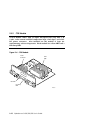
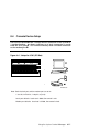
4.1
Rack System Characteristics
Table 4–1 lists system drawer characteristics. Table 4–2 lists power and
environmental specifications for the rack system.
Figure 4–1 System Drawer
PK-0633-99
Table 4–1 System Drawer Characteristics
Characteristic
Specification
Size
40 cm H x 45 cm W x 65 cm D (15 in. x 18 in. x
25 in.)
Weight
45 kg (100 lb) maximum
Maximum heat dissipation
1500 w (4910 Btu/hr)
4-2
AlphaServer GS80/160/320 User’s Guide
Table 4–2 Rack System Characteristics
Electrical
Voltage
120 VAC (U.S.)
220–240 VAC (Europe)
200–240 VAC (Japan)
Phase
Single
Frequency
50–60 Hz
Maximum input
current/circuit
16 A (U.S.)
12 A (Europe)
13 A (Japan)
Maximum power
consumption
2.4 – 2.8 KVA (U.S.)
5.2 – 5.7 KVA (Europe)
4.8 – 5.7 KVA (Japan)
Environmental
Temperature
Operating: 5° to 35°C (41 to 95°F)
Not operating: -40° to 66°C (-40° to 150°F)
Humidity
Operating: 10% to 90%
Not operating: 10% to 95%
Altitude
Operating: 0 to 3 km (0 to 10,000 ft)
Not operating: 0 to 12.2 km (0 to 40,000 ft)
GS80 Rack System Overview
4-3
4.2
System Drawer Architecture
The system drawer houses a QBB consisting of a backplane that
supports four CPU modules, four memory modules, two power modules
and two I/O riser modules. These modules are identical to those used in
the box systems. The global port is part of the backplane. In a twodrawer system, the drawers are linked by a distribution board.
Figure 4–2 Two-Drawer Block Diagram
System Drawer 1
PCI Box
CPU
I/O
CPU
CPU
CPU
Switch
MEM
MEM
MEM
GP
MEM
PCI Box
Distribution
Board
System Drawer 2
CPU
PCI Box
I/O
MEM
CPU
CPU
CPU
Switch
MEM
MEM
GP
MEM
PCI Box
PK-0630-99
4-4
AlphaServer GS80/160/320 User’s Guide
The switch that interconnects the CPU modules, memory modules, and I/O riser
modules is built into the system drawer backplane.
In a two-drawer system, the system drawers are linked together through the
global ports and the distribution board. A directory module is required in each
system drawer in a two-drawer system.
GS80 Rack System Overview
4-5
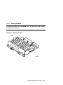
4.3
System Drawer Modules
The modules plug into the system drawer backplane. Figure 4–3 shows
a fully populated backplane. Figure 4–4 shows the backplane with no
modules.
Figure 4–3 System Drawer Modules
3
1
2
2
1
1
2
2
5
1
7
6
4
4
PK0619
4-6
AlphaServer GS80/160/320 User’s Guide
The CPU, memory, power, and I/O riser modules plug into the backplane
located at the bottom of the system drawer. Callouts in Figure 4–3 point to the
location of the following system drawer modules:
➊
➋
➌
CPU module
➍
➎
➏
➐
Power modules
Memory module
Directory module
Power system manager (PSM) module
I/O riser modules
Clock splitter module
Figure 4–4 System Drawer Backplane
3
2
1
2
1
4
1
2
1
2
5
7
6
PK-0632-99
GS80 Rack System Overview
4-7
Chapter 5
GS80 Rack System Configuration Rules
This chapter provides configuration rules for the following:
•
Rack
•
Rack Power System
GS80 Rack System Configuration Rules
5-1
5.1
Rack
A rack houses a maximum of two system drawers.
Figure 5–1 Rack
COMPAQ
AlphaServer GS80
LA75 Companion Printer
d i g i t a l
PK-0635-99
5-2
AlphaServer GS80/160/320 User’s Guide
About the Rack Cabinet
The cabinet contains the following components:
•
One or two system drawers
•
Control panel (see Section 2.6 for details on the control panel)
•
AC input box
•
Power subrack with power supplies
•
Vertical mounting rails
•
Stabilizer
•
Wrist strap for static discharge protection
Rack Variants
The H9A20 RETMA cabinet has three variants:
•
H9A20-CA, North American (120V)
•
H9A20-CB, European (220–240V)
•
H9A20-CC, North American and Japanese (200–240V)
GS80 Rack System Configuration Rules
5-3
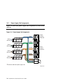
5.2
Rack Power System
Figure 5–2 shows a two-drawer rack power system: two AC input boxes
and two H7504 power subracks at the bottom of the cabinet. Each
subrack holds three power supplies. The system drawer power cables
connect to the power subrack.
Figure 5–2 Two-Drawer Rack Power System
Power Supply Positions
1
2
3
Drawer 2
R
Power Subrack 2
Drawer 1
H7504 (2)
R
Power Subrack 1
R Redundant Power
H7504 (1)
AC Input Box 2
AC Input Box 1
Supply Location
PK-0638-99
5-4
AlphaServer GS80/160/320 User’s Guide
About the Power System
•
Each system drawer requires one power subrack.
•
Each system drawer requires two power supplies.
•
Each power subrack holds up to three power supplies. The third power
supply is used for redundancy.
GS80 Rack System Configuration Rules
5-5
Chapter 6
Booting and Installing an
Operating System
This chapter provides basic operating instructions, including powering up the
system and booting the operating system.
Sections in this chapter are:
•
Powering Up the System
•
Setting Boot Options
•
Booting Tru64 UNIX
•
Installing Tru64 UNIX
•
Booting OpenVMS
•
Installing OpenVMS
Booting and Installing an Operating System
6-1
6.1
Powering Up the System
To power up the system, set the keyswitch to On, or power up the
system remotely. The SCM power-up display is shown at the system
management console and the control panel, followed by the SRM
power-up display.
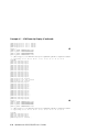
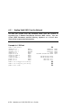
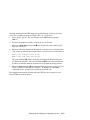
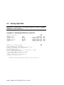
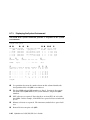
6.1.1
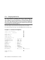
SCM Power-Up Display
Example 6–1 SCM Power-Up Display
➊
SCM_E0> power on
Powering on PCI Box 0
Powering on PCI Box 1
QBB-0 Powering ON
➋
➌
~I~ Testing OCP Switch passed
Power
QBB-1
QBB-2
QBB-3
ON Phase
Powering
Powering
Powering
INIT
ON
ON
ON
SCM_E0>
Testing SIO Shared RAM(please wait)
Initializing shared ram
Shared RAM Initialized
Powering ON H-Switch
SCM_E0>
I~ HSW4/HPM40 SysEvent: HS_INIT_CD1
Reg0:000F Reg1:AB81
Phase 0
I~ Enable HS Links: 0f
~I~ QbbConf(gp/io/c/m)=fbbfffff Assign=ff SQbb0=00 PQbb=00 SoftQbbId=fedcba98
~I~ SysConfig: 37 13 07 19 07 12 c7 13 37 13 f7 11 f7 13 37 13
SCM_E0>
I~ HSW4/HPM40 SysEvent: LINK0_ON
Reg0:000F Reg1:AB81
SCM_E0>
I~ HSW4/HPM40 SysEvent: LINK1_ON
Reg0:010F Reg1:AB81
SCM_E0>
I~ HSW4/HPM40 SysEvent: LINK2_ON
Reg0:030F Reg1:AB81
SCM_E0>
I~ HSW4/HPM40 SysEvent: LINK3_ON
Reg0:070F Reg1:AB81
SCM_E0>
.............................................................................
.........................................................................
SCM_E0> ......................................
6-2
AlphaServer GS80/160/320 User’s Guide
➊
The user issues a power on command.
➋
Messages denoted by ~I~ are informational and do not indicate a serious
event. Other types of messages include:
*** – Diagnostic format indicating an error has occurred.
### – Diagnostic format indicating a warning.
~E~ – An error has occurred; power-up continues, but the affected resource
is dropped.
~W~ – An error has occurred; power-up continues, and the affected
resource is questionable.
➌
During the Phase INIT (initialization phase) SROM code is loaded into
each CPU in the system and communication between the power system
manager (PSM) and the CPU is established. Phase 0 follows with local
QBB testing.
Continued on next page
Booting and Installing an Operating System
6-3
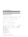
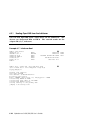
Example 6–1 SCM Power-Up Display (Continued)
QBB2 Step(s)-0 1 2 3 4 5 Tested
QBB3 Step(s)-0 1 2 3 4 5 Tested
QBB0 Step(s)-0 1 2 3 4 5 Tested
QBB1 Step(s)-0 1 2 3 4 5 Tested
Phase 1
QBB0 IO_MAP0: 000000C101311133
QBB1 IO_MAP1: 0000000000000003
QBB2 IO_MAP2: 0000000000000003
QBB3 IO_MAP3: 000000C001311133
➍
~I~ QbbConf(gp/io/c/m)=fbbfffff Assign=ff SQbb0=00 PQbb=00 SoftQbbId=fedcba98
~I~ SysConfig: 37 13 07 19 07 12 c7 13 37 13 f7 11 f7 13 37 13
SCM_E0>
QBB1 now Testing Step-6
QBB1 now Testing Step-7
QBB1 now Testing Step-8
QBB1 now Testing Step-9
QBB1 now Testing Step-A
QBB2 now Testing Step-6
QBB2 now Testing Step-7
QBB3 now Testing Step-6
QBB3 now Testing Step-7
QBB3 now Testing Step-8
QBB3 now Testing Step-9
QBB3 now Testing Step-A.
QBB0 now Testing Step-6
QBB1 Step(s)-A B Tested
QBB2 Step(s)-7 8 9 A B Tested
QBB3 Step(s)-A B Tested.
QBB0 now Testing Step-7.
QBB0 now Testing Step-8..
QBB0 now Testing Step-9...
QBB0 now Testing Step-A..
QBB0 now Testing Step-7.
QBB0 now Testing Step-8...
QBB0 now Testing Step-9..
QBB0 now Testing Step-A..
QBB0 now Testing Step-7.
QBB0 now Testing Step-8...
QBB0 now Testing Step-9...
QBB0 now Testing Step-A..
QBB0 now Testing Step-B..
Phase 2
➎
QBB0 IO_MAP0: 000000C101311133
QBB1 IO_MAP1: 0000000000000003
QBB2 IO_MAP2: 0000000000000003
QBB3 IO_MAP3: 000000C001311133
~I~ QbbConf(gp/io/c/m)=fbbfffff Assign=ff SQbb0=00 PQbb=00 SoftQbbId=fedcba98
~I~ SysConfig: 37 13 07 19 07 12 c7 13 37 13 f7 11 f7 13 37 13
SCM_E0>
QBB1 now Testing Step-C
QBB2 now Testing Step-C
QBB3 now Testing Step-C
QBB0 Step(s)-B C Tested...
6-4
AlphaServer GS80/160/320 User’s Guide
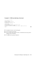
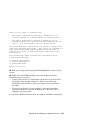
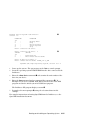
Example 6–1 SCM Power-Up Display (Continued)
Phase 3
➏
~I~ QbbConf(gp/io/c/m)=fbbfffff Assign=ff SQbb0=00 PQbb=00 SoftQbbId=fedcba98
~I~ SysConfig: 37 13 07 19 07 12 c7 13 37 13 f7 11 f7 13 37 13
SCM_E0>
QBB0 now Testing Step-D
QBB1 now Testing Step-D
QBB2 now Testing Step-D
QBB3 now Testing Step-D.............
QBB0 IO_MAP0: 000000C101311133
QBB1 IO_MAP1: 0000000000000003
QBB2 IO_MAP2: 0000000000000003
QBB3 IO_MAP3: 000000C001311133
Phase 4
➐
~I~ QbbConf(gp/io/c/m)=fbbfffff Assign=ff SQbb0=00 PQbb=00 SoftQbbId=fedcba98
QBB0 unloading console across port0 from PCI Box-1
Console COM1 from master PCI Box-0
~I~ SysConfig: 37 13 07 19 07 12 c7 13 37 13 f7 11
Retrieving FRU information for Shared RAM...
SCM_E0>
QBB0 now Testing Step-E..
Power On Complete
f7 13
37 13
➑
Returning to system COM1 port
➍
Phase 1. The primary CPU, selected by the SCM in phase 0, tests each
QBB in the system.
➎
Phase 2. Secondary CPUs are tested to ensure cache coherency.
➏
Phase 3. The tests ensure that each CPU can access each memory array in
the system.
➐
Phase 4. The primary CPU unloads the PAL/console code from the flash
ROM on the standard I/O module into memory.
➑
Control of the remainder of power-up is passed to the console firmware.
See Section 6.1.2.
Booting and Installing an Operating System
6-5
6.1.2
SRM Power-Up Display
Following the initial SCM power-up and the five test phases, the SRM
console takes control of the remaining portion of system power-up.
Example 6–2 SRM Power-Up Display
System Primary QBB0 : 0
System Primary CPU : 0 on QBB0
Par hrd/sft CPU Mem
QBB#
3210 3210
IOR3 IOR2 IOR1 IOR0
(pci_box.rio)
GP QBB
Mod BP
Dir PS Temp
Mod 321 (:C)
(-)
(-)
(-)
(-)
--.--.--.--.-
P
P
P
P
P
P
P
P
0/30
1/31
2/32
3/33
---P
-P-P
--P---P
HSwitch
Type
HPM40
4-port
PCI Rise1-1
Cab 7 6 5 4
10
11
- - - - - - -
PP
PP
--P-P--
--.--.--.--.-
Px.x
--.--.Px.x
P1.0
--.--.P0.0
Cables 7 6 5 4 3 2 1 0
P
P
P
P
PPP
PPP
PPPP-
➊
26.5
29.0
25.0
27.0
Temp(:C)
- - - - E E E E
29.0
Rise1-0
3 2 1
Rise0-1
7 6 5 4
Rise0-0
3 2 1
RIO
1 0
PS
21
Temp
(:C)
- - - - -
- - - - - L -
- - S
L M S
- *
- *
PPP
27.5
27.0
OpenVMS PALcode V1.75-1, Tru64 UNIX PALcode V1.68-1
system = QBB 0 1 2 3
+ HS
QBB 0 = CPU 0
+ Mem 0 1
QBB 1 = CPU 0
2
+ Mem 0 1
QBB 2 = CPU
1
+ Mem
1
QBB 3 = CPU 0
+ Mem
2
shared RAM version is 1.3
hose 24 has a standard I/O module
starting console on CPU 0
initialized idle PCB
initializing semaphores
initializing heap
initial heap 2c0c0
memory low limit = 1f2000
heap = 2c0c0, 1ffc0
initializing
initializing
initializing
initializing
lowering IPL
6-6
+
+
+
+
Dir
Dir
Dir
Dir
+
+
+
+
IOP
IOP
IOP
IOP
driver structures
idle process PID
file system
timer data structures
AlphaServer GS80/160/320 User’s Guide
+
+
+
+
PCA 0
PCA
PCA
PCA 0
+
+
+
+
GP
GP
GP
GP
(Hard
(Hard
(Hard
(Hard
QBB
QBB
QBB
QBB
➋
➌
0)
1)
2)
3)
➊
A snapshot of the system environment is displayed. See Section 8.7.3 for
more information.
➋
PALcode is loaded and started.
➌
The size of the system is determined and mapped. This system has four
QBBs and five CPUs.
Continued on next page
Booting and Installing an Operating System
6-7
Example 6–2 SRM Power-Up Display (Continued)
CPU 0 speed is 731 MHz
create dead_eater
create poll
create timer
create powerup
access NVRAM
QBB 0 memory, 1 GB
QBB 1 memory, 1 GB
QBB 2 memory, 512 MB
QBB 3 memory, 512 MB
total memory, 3 GB
copying PALcode to 103ffe8000
copying PALcode to 201ffe8000
copying PALcode to 301ffe8000
probe I/O subsystem
probing hose 0, PCI
probing PCI-to-ISA bridge, bus 1
bus 1, slot 0 -- dva—Floppy
bus 0, slot 1 -- pka—QLogic ISP10x0
bus 0, slot 2 -- vga—ELSA GLoria Synergy
bus 0, slot 3 -- pkb—QLogic ISP10x0
bus 0, slot 15 -- dqa—Acer Labs M1543C IDE
bus 0, slot 15 -- dqb—Acer Labs M1543C IDE
probing hose 1, PCI
bus 0, slot 5 -- ewa—DE500-BA Network Controller
probing hose 24, PCI
probing PCI-to-ISA bridge, bus 1
bus 1, slot 0 -- dvb—Floppy
bus 0, slot 1 -- pkc—QLogic ISP10x0
bus 0, slot 15 -- dqc—Acer Labs M1543C IDE
bus 0, slot 15 -- dqd—Acer Labs M1543C IDE
probing hose 25, PCI
starting drivers
*** keyboard not plugged in...
entering idle loop
initializing keyboard
*** keyboard not plugged in...
starting console on CPU 4
initialized idle PCB
initializing idle process PID
lowering IPL
CPU 4 speed is 731 MHz
create powerup
starting console on CPU 6
initialized idle PCB
initializing idle process PID
lowering IPL
CPU 6 speed is 731 MHz
create powerup
starting console on CPU 9
initialized idle PCB
initializing idle process PID
lowering IPL
➍
➎
➏
Continued on next page
6-8
AlphaServer GS80/160/320 User’s Guide
Example 6–2 SRM Power-Up Display (Continued)
CPU 9 speed is 731 MHz
create powerup
starting console on CPU 12
initialized idle PCB
initializing idle process PID
lowering IPL
CPU 12 speed is 731 MHz
create powerup
initializing pka pkb pkc ewa dqa dqb dqc dqd
initializing GCT/FRU at 1f2000
AlphaServer Console X5.7-6290, built on Feb 4 2000 at 01:41:06
P00>>>
➍
➎
➏
Distributed memory is sized and mapped.
➐
The SRM console prompt is displayed.
➐
The I/O subsystem is mapped.
Each secondary CPU starts the console, is initialized and ready to join the
multiprocessor environment.
Booting and Installing an Operating System
6-9
6.2
Setting Boot Options
You can set a default boot device, boot flags, and network boot
protocols for Tru64 UNIX or OpenVMS using the SRM set command
with environment variables. Once these environment variables are set,
the boot command defaults to the stored values. You can override the
stored values for the current boot session by entering parameters on
the boot command line.
The SRM boot-related environment variables are listed below and described in
the following sections:
bootdef_dev
Defines a default boot device.
boot_file
Specifies a default file name to be used for booting when
no file name is specified by the boot command.
boot_osflags
Defines parameters to enable specific functions during the
boot process.
ei*0_inet_init or
ew*0_inet_init
Determines whether the interface’s internal Internet
database is initialized from nvram or from a network
server (through the bootp protocol). Set this environment
variable if you are booting Tru64 UNIX from a RIS server.
ei*0_protocols or
ew*0_protocols
Defines a default network boot protocol (bootp or mop).
6.2.1
Bootdef_dev
The bootdef_dev environment variable specifies one or more devices
from which to boot the operating system. When more than one device is
specified, the system searches in the order listed and boots from the
first device.
Enter the show bootdef_dev command to display the current default boot
device. Enter the show device command for a list of all devices in the system.
6-10
AlphaServer GS80/160/320 User’s Guide
The syntax is:
set bootdef_dev boot_device
boot_device
The name of the device on which the system software has
been loaded. To specify more than one device, separate the
names with commas.
Example
In this example, two boot devices are specified. The system will try booting
from dkb0 and, if unsuccessful, will boot from dka0.
P00>>> set bootdef_dev dkb0, dka0
NOTE: When you set the bootdef_dev environment variable, it is recommended that you set the operating system boot parameters as well, using the
set boot_osflags command.
6.2.2
Boot_file
The boot_file environment variable specifies the default file name to be
used for booting when no file name is specified by the boot command.
The syntax is:
set boot_file filename
Example
In this example, a boot file is specified for booting OpenVMS from the
InfoServer. APB_0712 is the file name of the APB program used for the
initial system load (ISL) boot program.
P00>>> set boot_file apb_0712
Booting and Installing an Operating System
6-11
6.2.3
Boot_osflags
The boot_osflags environment variable sets the default boot flags and,
for OpenVMS, a root number.
Boot flags contain information used by the operating system to determine some
aspects of a system bootstrap. Under normal circumstances, you can use the
default boot flag settings.
To change the boot flags for the current boot only, use the flags_value argument
with the boot command.
The syntax is:
set boot_osflags flags_value
The flags_value argument is specific to the operating system.
Tru64 UNIX Systems
Tru64 UNIX systems take a single ASCII character as the flags_value
argument.
a
Load operating system software from the specified boot device
(autoboot). Boot to multiuser mode.
i
Prompt for the name of a file to load and other options (boot
interactively). Boot to single-user mode.
s
Stop in single-user mode. Boots /vmunix to single-user mode and stops
at the # (root) prompt.
D Full dump; implies “s” as well. By default, if Tru64 UNIX crashes, it
completes a partial memory dump. Specifying “D” forces a full dump at
system crash.
6-12
AlphaServer GS80/160/320 User’s Guide
OpenVMS Systems
OpenVMS systems require an ordered pair as the flags_value argument:
root_number and boot_flags.
root_number
Directory number of the system disk on which OpenVMS files
are located. For example:
boot_flags
root_number
Root Directory
0 (default)
[SYS0.SYSEXE]
1
[SYS1.SYSEXE]
2
[SYS2.SYSEXE]
3
[SYS3.SYSEXE]
The hexadecimal value of the bit number or numbers set. To
specify multiple boot flags, add the flag values (logical OR).
For example, the flag value 10080 executes both the 80 and
10000 flag settings. See Table 6–1.
Table 6–1 OpenVMS Boot Flag Settings
Flags_Value
Bit Number
Meaning
1
0
Bootstrap conversationally (enables you to
modify SYSGEN parameters in SYSBOOT).
2
1
Map XDELTA to a running system.
4
2
Stop at initial system breakpoint.
8
3
Perform diagnostic bootstrap.
10
4
Stop at the bootstrap breakpoints.
20
5
Omit header from secondary bootstrap image.
80
7
Prompt for the name of the secondary bootstrap
file.
100
8
Halt before secondary bootstrap.
10000
16
Display debug messages during booting.
20000
17
Display user messages during booting.
Continued on next page
Booting and Installing an Operating System
6-13
Example
In the following Tru64 UNIX example, the boot flags are set to autoboot the
system to multiuser mode when you enter the boot command.
P00>>> set boot_osflags a
In the following OpenVMS example, root_number is set to 2 and boot_flags is set
to 1. With this setting, the system will boot from root directory SYS2.SYSEXE
to the SYSBOOT prompt when you enter the boot command.
P00>>> set boot_osflags 2,1
In the following OpenVMS example, root_number is set to 0 and boot_flags is
set to 80. With this setting, you are prompted for the name of the secondary
bootstrap file when you enter the boot command.
P00>>> set boot_osflags 0,80
6.2.4
ei*0_inet_init or ew*0_inet_init
The ei*0_inet_init or ew*0_inet_init environment variable determines
whether the interface’s internal Internet database is initialized from
nvram or from a network server (through the bootp protocol).
Legal values are nvram and bootp. The default value is bootp. Set this
environment variable if you are booting Tru64 UNIX from a RIS server.
To list the network devices on your system, enter the show device command.
The Ethernet controllers start with the letters “ei” or “ew,” for example, ewa0.
The third letter is the adapter ID for the specific Ethernet controller. Replace
the asterisk (*) with the adapter ID letter when entering the command.
The syntax is:
set ei*0_inet_init value or
set ew*0_inet_init value
Example
P00>>> set eia0_inet_init bootp
6-14
AlphaServer GS80/160/320 User’s Guide
6.2.5
ei*0_protocols or ew*0_protocols
The ei*0_protocols or ew*0_protocols environment variable sets
network protocols for booting and other functions.
To list the network devices on your system, enter the show device command.
The Ethernet controllers start with the letters “ei” or “ew,” for example, eia0.
The third letter is the adapter ID for the specific Ethernet controller. Replace
the asterisk (*) with the adapter ID letter when entering the command.
The syntax is:
set ei*0_protocols protocol_value or
set ew*0_protocols protocol_value
The options for protocol_value are:
mop (default)
Sets the network protocol to mop (Maintenance Operations
Protocol), the setting typically used with the OpenVMS
operating system.
bootp
Sets the network protocol to bootp, the setting typically used
with the Tru64 UNIX operating system.
bootp,mop
When both are listed, the system attempts to use the mop
protocol first, regardless of which is listed first. If not
successful, it then attempts the bootp protocol.
Example
P00>>> show device
.
.
.
eia0.0.0.1001.0
EIA0
eib0.0.0.12.0
EIB0
eic0.0.0.13.0
EIC0
.
.
.
P00>>> set eia0_protocols bootp
P00>>> show eia0_protocols
eia0_protocols
bootp
08-00-2B-3E-BC-B5
00-00-C0-33-E0-0D
08-00-2B-E6-4B-F3
Booting and Installing an Operating System
6-15
6.3
Booting Tru64 UNIX
Tru64 UNIX can be booted from a DVD or CD-ROM on a local drive,
from a local SCSI disk, or from a server.
Example 6–3 Booting Tru64 UNIX from a Local SCSI Disk
P00>>> sho dev
dka0.0.0.1.0
dka100.1.0.1.1
dka200.2.0.1.1
dka300.3.0.1.1
dkc0.0.0.1.0
dkc100.1.0.1.0
dkc200.2.0.1.0
dkc300.3.0.1.0
dqa0.0.0.15.0
dva0.0.0.1000.0
DKA0
DKA100
DKA200
DKA300
DKC0
DKC100
DKC200
DKC300
DQA0
DVA0
RZ2ED-LS
RZ2ED-LS
RZ2DD-LS
RZ2DD-LS
RZ2DD-LS
RZ2DD-LS
RZ2DD-LS
RZ2DD-LS
TOSHIBA CD-ROM XM-6202B
P00>>> boot
(boot dka0.0.0.1.0 -flags a)
block 0 of dka0.0.0.1.0 is a valid boot block
reading 13 blocks from dka0.0.0.1.0
bootstrap code read in
base = 2e6000, image_start = 0, image_bytes = 1a00
initializing HWRPB at 2000
initializing page table at 17fbda000
initializing machine state
setting affinity to the primary CPU
jumping to bootstrap code
➊
0306
0306
0306
0306
0306
0306
0306
0306
1110
➋
➌
Tru64 UNIX boot - Wed Sep 8 20:59:58 EDT 1999
Loading vmunix ...
Loading at 0xfffffc0000430000
Sizes:
text = 4800560
data = 903872
bss = 1412480
Starting at 0xfffffc00007790d0
Loading vmunix symbol table ... [1330800 bytes]
Alpha boot: available memory from 0x93de000 to 0x3180000000
Digital Tru64 UNIX V4.0G-1 (Rev. 1398); Thu Oct 21 13:34:00 EDT 1999
physical memory = 24572.00 megabytes.
available memory = 24140.65 megabytes.
using 94344 buffers containing 737.06 megabytes of memory
Master cpu at slot 0.
6-16
AlphaServer GS80/160/320 User’s Guide
Example 6–3 Booting Tru64 UNIX from a Local SCSI Disk (Continued)
Firmware revision: 5.6-6930
PALcode: Digital Tru64 UNIX version 1.60-1
Compaq AlphaServer GS320 6/731
.
.
.
Digital Tru64 UNIX Version V4.0
login:
Example 6–3 shows a boot from a local SCSI drive. The example is abbreviated.
For complete instructions on booting Tru64 UNIX, see the Tru64 UNIX
Installation Guide.
Perform the following tasks to boot a system:
1. Power up the system. The system stops at the SRM console prompt,
P00>>>.
2. Set boot environment variables, if desired. See Section 6.2.
3. Install the boot medium. For a network boot, see Section 6.3.1.
4. Enter the show device command ➊ to determine the unit number of the
drive for your device.
5. Enter the boot command ➋ and command-line parameters (if you have not
set the associated environment variables). In Example 6–3, boot device and
boot flags ➌ have already been set.
Booting and Installing an Operating System
6-17
6.3.1
Booting Tru64 UNIX Over the Network
To boot the system over the network, make sure the system is
registered on a Remote Installation Services (RIS) server. See the
Tru64 UNIX document entitled Sharing Software on a Local Area
Network for registration information.
Example 6–4 RIS Boot
P00>>> show device
dka0.0.0.1.1
DKA0
dka100.1.0.1.1
DKA100
dka200.2.0.1.1
DKA200
dkb0.0.0.3.1
DKB0
dqa0.0.0.15.0
DQA0
dva0.0.0.1000.0
DVA0
eia0.0.0.4.1
EIA0
eib0.0.0.2002.1
EIB0
pka0.7.0.1.1
PKA0
pkb0.7.0.3.1
PKB0
P00>>> set eia0_protocols bootp
P00>>> set eia0_inet_init bootp
P00>>> boot eia0
.
6-18
➊
RZ2DD-LS
RZ2DD-LS
RZ1CB-CS
RZ25
TOSHIBA CD-ROM XM-6302B
AlphaServer GS80/160/320 User’s Guide
00-00-F8-09-90-FF
00-06-2B-00-25-5B
SCSI Bus ID 7
SCSI Bus ID 7
➋
➌
➍
0306
0306
0844
0900
1012
Systems running Tru64 UNIX support network adapters, designated ew*0 or
ei*0. The asterisk stands for the adapter ID (a, b, c, and so on).
1.
Power up the system. The system stops at the SRM console prompt,
P00>>>.
2.
Set boot environment variables, if desired. See Section 6.2.
3.
Enter the show device command ➊ to determine the unit number of the
drive for your device.
4.
Enter the following commands. Example 6–4 assumes you are booting from
eia0. If you are booting from another drive, enter that device name instead.
P00>>> set eia0_protocols bootp
P00>>> set eia0_inet_init bootp
The first command ➋ enables the bootp network protocol for booting over
the Ethernet controller. The second command ➌ sets the internal Internet
database to initialize from the network server through the bootp protocol.
5.
Enter the boot command ➍ and command-line parameters (if you have not
set the associated environment variables). In Example 6–4 the boot
command sets the system to boot automatically from eia0.
For complete instructions on booting Tru64 UNIX over the network, see the
Tru64 UNIX Installation Guide.
Booting and Installing an Operating System
6-19
6.4
Installing Tru64 UNIX
Tru64 UNIX is installed from the DVD/CD-ROM drive connected to the
system.
Example 6–5 Tru64 UNIX Installation Display
P00>>> b dqa0
(boot dqa0.0.0.15.0 -flags a
block 0 of dqa0.0.0.15.0 is a valid boot block
reading 16 blocks from dqa0.0.0.15.0
bootstrap code read in
base = 200000, image_start = 0, image_bytes = 2000
initializing HWRPB at 2000
initializing page table at 1fff0000
initializing machine state
setting affinity to the primary CPU
jumping to bootstrap code
➊
Tru64 UNIX boot - Thu Jan 14 15:03:19 EST 1999
Loading vmunix ...
.
.
Initializing system for Tru64 UNIX installation.
wait...
Please
*** Performing CDROM Installation
Loading installation process and scanning system hardware.
Welcome to the Tru64 UNIX Installation Procedure
➋
This procedure installs Tru64 UNIX onto your system. You will
be asked a series of system configuration questions. Until
you answer all questions, your system is not changed in any
way.
During the question and answer session, you can go back to any
previous question and change your answer by entering: history
You can get more information about a question by entering:
help
6-20
AlphaServer GS80/160/320 User’s Guide
There are two types of installations:
o
The Default Installation installs a mandatory set of
software subsets on a predetermined file system layout.
o
The Custom Installation installs a mandatory set of
software subsets plus optional software subsets that you
select. You can customize the file system layout.
The Tru64 UNIX Shell option puts your system in single-user
mode with superuser privileges. This option is provided for
experienced Tru64 UNIX system administrators who want to
perform file system or disk maintenance tasks before the
installation.
The Installation Guide contains more information about
installing Tru64 UNIX.
1) Default Installation
2) Custom Installation
3) Tru64 UNIX Shell
Enter your choice:
➊ Boot the operating system from the DVD/CD-ROM drive connected to the
system.
➋ Follow the Tru64 UNIX installation procedure displayed after the
installation process is loaded.
•
If your system console is a VGA monitor, the X Server is started and an
Installation Setup window is displayed. Click on the fields in the
Installation Setup window to enter your responses to the installation
procedure.
•
If your system console is a serial terminal, a text-based installation
procedure is displayed, as shown in Example 6–5. Enter the choices
appropriate for your system.
See the Tru64 UNIX Installation Guide for complete installation instructions.
Booting and Installing an Operating System
6-21
6.5
Booting OpenVMS
OpenVMS is booted from a local SCSI disk drive or from a DVD/CDROM drive on the InfoServer.
Example 6–6 Booting OpenVMS from a Local Disk
P00>>> show device
dka0.0.0.1.0
DKA0
dkb0.0.0.3.0
DKB0
COMPAQ
dkb100.1.0.3.0
DKB100
COMPAQ
dkb200.2.0.3.0
DKB200
COMPAQ
dkb300.3.0.3.0
DKB300
COMPAQ
dkc0.0.0.4.1
DKC0
COMPAQ
.
.
.
P00>>> boot -flags 0,0 dka0
(boot dka0.0.0.1.0 -flags 0,0)
block 0 of dka0.0.0.1.0 is a valid boot block
reading 924 blocks from dka0.0.0.1.0
bootstrap code read in
base = 2c4000, image_start = 0, image_bytes = 73800
initializing HWRPB at 2000
initializing page table at 2bfbc6000
initializing machine state
setting affinity to the primary CPU
jumping to bootstrap code
OpenVMS (TM) Alpha Operating System, Version B7.2-1H1
6-22
AlphaServer GS80/160/320 User’s Guide
➊
RZ1DF-BF
BB00911CA0
BB00911CA0
BB00911CA0
BB00911CA0
BB00911CA0
➋
1614
3B05
3B05
3B05
3B05
3B05
Example 6–6 shows a boot from a local disk. The example is abbreviated. For
complete instructions on booting OpenVMS, see the OpenVMS installation
document.
1.
Power up the system. The system stops at the SRM console prompt,
P00>>>.
2.
Set boot environment variables, if desired. See Section 6.2.
3.
Install the boot medium. For a network boot, see Section 6.2.4.
4.
Enter the show device command ➊ to determine the unit number of the
drive for your device.
5.
Enter the boot command and command-line parameters (if you have not set
the associated environment variables.). In Example 6–6, the boot command
with the -flags option ➋ causes the system to boot from [SYS0.EXE] on
device DKA0.
Booting and Installing an Operating System
6-23
6.5.1
Booting OpenVMS from the InfoServer
You can boot OpenVMS from a LAN device on the InfoServer. The
devices are designated EI*0 or EW*0. The asterisk stands for the
adapter ID (a, b, c, and so on).
Example 6–7 InfoServer Boot
P00>>> show device
➊
dka0.0.0.1.1
DKA0
RZ2CA-LA
dka100.1.0.1.1
DKA100
RZ2CA-LA
dqa0.0.0.15.0
DQA0
TOSHIBA CD-ROM XM-6302B
dva0.0.0.1000.0
DVA0
eia0.0.0.6.1
EIA0
00-00-F8-10-D6-03
pka0.7.0.1.1
PKA0
SCSI Bus ID 7
P00>>>
.
.
.
P00>>> boot -flags 0,0 -file apb_0712 eia0
➋
(boot eia0.0.0.6.1 -file APB_0712 -flags 0,0)
Trying MOP boot.
.............
Network load complete.
Host name: CALSUN
Host address: aa-00-04-00-a4-4e
bootstrap code read in
base = 200000, image_start = 0, image_bytes = 70400
initializing HWRPB at 2000
initializing page table at 3ffee000
initializing machine state
setting affinity to the primary CPU
jumping to bootstrap code
6-24
AlphaServer GS80/160/320 User’s Guide
N1H0
N1H0
1012
Network Initial System Load Function
Version 1.2
➌
FUNCTION
FUNCTION
ID
1
Display Menu
2
Help
3
Choose Service
4
Select Options
5
Stop
Enter a function ID value:
Enter a function ID Value: 3
OPTION
OPTION
ID
1
Find Services
2
Enter known Service Name
➍
Enter an Option ID value: 2
Enter a Known Service Name: ALPHA_V71-2_SSB
OpenVMS (TM) Alpha Operating System, Version V7.1-2
1.
Power up the system. The system stops at the P00>>> console prompt.
2.
Insert the operating system DVD/CD-ROM into the drive connected to the
InfoServer.
3.
Enter the show device command ➊ to determine the unit number of the
drive for your device.
4.
Enter the boot command and any command-line parameters ➋. In
Example 6–7 the device is EIA0. APB_0712 is the file name of the APB
program used for the initial system load (ISL) boot program.
The InfoServer ISL program displays a menu ➌.
5.
Respond to the menu prompts ➍, using the selections shown in this
example.
For complete instructions on booting OpenVMS from the InfoServer, see the
OpenVMS installation document.
Booting and Installing an Operating System
6-25
6.6
Installing OpenVMS
After you boot the operating system DVD or CD-ROM, an installation
menu is displayed on the screen. Choose item 1 (Install or upgrade
OpenVMS Alpha). Refer to the OpenVMS installation document for
information on creating the system disk.
Example 6–8 OpenVMS Installation Menu
OpenVMS (TM) Alpha Operating System, Version V7.1-2
➊
Copyright © 1999 Digital Equipment Corporation. All rights reserved.
Installing required known files...
Configuring devices...
****************************************************************
You can install or upgrade the OpenVMS Alpha operating system
or you can install or upgrade layered products that are included
on the OpenVMS Alpha operating system CD-ROM.
You can also execute DCL commands and procedures to perform
"standalone" tasks, such as backing up the system disk.
Please choose one of the following:
1)
2)
3)
4)
5)
6)
7)
8)
Install or upgrade OpenVMS Alpha Version V7.1-2
Display products that this procedure can install
Install or upgrade layered products
Show installed products
Reconfigure installed products
Remove installed products
Execute DCL commands and procedures
Shut down this system
Enter CHOICE or ? for help: (1/2/3/4/5/6/7/8/?) 1
6-26
AlphaServer GS80/160/320 User’s Guide
➋
➊
➋
The OpenVMS operating system DVD/CD-ROM is booted.
Choose option 1 (Install or upgrade OpenVMS Alpha). To create the system
disk, see the OpenVMS installation document.
Booting and Installing an Operating System
6-27
Chapter 7
Operation
This chapter gives basic operating instructions. Sections include:
•
SRM Console
•
Displaying a Tru64 UNIX or OpenVMS Configuration
•
Setting SRM Environment Variables
•
Setting SRM Console Security
•
Setting Automatic Booting
•
Changing the Default Boot Device
•
Soft Partitioning
•
Hard Partitioning
Operation
7-1
7.1
SRM Console
The SRM console is located in an EEROM on the standard I/O module.
From the console interface, you set up and boot the operating system,
display the system configuration, and perform other tasks.
For
complete information on the SRM console, see the AlphaServer
GS80/160/320 Firmware Reference Manual.
7.1.1
SRM Command Overview
Table 7–1 summarizes the most frequently used SRM console
commands; Table 7–2 gives the command notation formats; and Table
7–3 shows special characters used on the command line.
Table 7–1 Summary of SRM Commands
Command
Function
boot
Loads and starts the operating system.
continue
Resumes program execution on the specified processor or on
the primary processor if none is specified.
crash
Forces a crash dump at the operating system level.
edit
Invokes the console line editor on a RAM script or on the
user power-up script, “nvram,” which is always invoked
during the power-up sequence.
help (or man)
Displays information about the specified console command.
init
Resets the SRM console and reinitializes the hardware.
more
[filename]
Displays a file one screen at a time.
set envar
Sets or modifies the value of an environment variable.
show envar
Displays the state of the specified environment variable.
7-2
AlphaServer GS80/160/320 User’s Guide
Table 7–1 Summary of SRM Commands (Continued)
Command
Function
show config
Displays the logical configuration at the last system
initialization.
show device
Displays a list of controllers and bootable devices in the
system.
show error
Reports errors logged in the EEPROMs.
show fru
Displays the physical configuration of all field-replaceable
units (FRUs).
show memory
Displays information about system memory.
show pal
Displays the versions of Tru64 UNIX and OpenVMS
PALcode.
show version
Displays the version of the SRM console program installed
on the system.
test
Verifies the configuration of the devices in the system.
<esc><esc>scm
Escape sequence used to enter the SCM console.
Operation
7-3
Table 7–2 Notation Formats for SRM Console Commands
Attribute
Conditions
Length
Up to 255 characters, not including the terminating carriage
return or any characters deleted as the command is entered.
To enter a command longer than 80 characters, use the
backslash character for line continuation.
Case
Upper- or lowercase characters can be used for input.
Characters are displayed in the case in which they are entered.
Abbreviation
Only by dropping characters from the end of words. You must
enter the minimum number of characters to identify the
keyword unambiguously.
Options
You can use command options, to modify the environment,
after the command keyword or after any symbol or number in
the command. See individual command descriptions for
examples.
Numbers
Most numbers in console commands are in decimal notation.
No
characters
A command line with no characters is a null command. The
console program takes no action and does not issue an error
message; it returns the console prompt. The console supports
command-line recall and editing.
Spaces or
tabs
Multiple adjacent spaces and tabs are compressed and treated
as a single space. Leading and trailing spaces are ignored.
7-4
AlphaServer GS80/160/320 User’s Guide
Table 7–3 Special Characters for SRM Console
Character
Function
Return or
Enter
Terminates a command line. No action is taken on a
command until it is terminated. If no characters are
entered and this key is pressed, the console just redisplays
the prompt.
Backslash (\)
Continues a command on the next line. Must be the last
character on the line to be continued.
Delete
Deletes the previous character.
Ctrl/A
Toggles between insert and overstrike modes. The default
is overstrike.
Ctrl/B or
up-arrow
Recalls previous command or commands. The last 16
commands are stored in the recall buffer.
Ctrl/C
Terminates the process that is running. Clears Ctrl/S;
resumes output suspended by Ctrl/O. When entered as part
of a command line, deletes the current line. Ctrl/C has no
effect as part of a binary data stream.
Left-arrow
Moves the cursor left one position.
Ctrl/E
Moves the cursor to the end of the line.
Ctrl/F or
right-arrow
Moves the cursor right one position.
Ctrl/H
Moves the cursor to the beginning of the line.
Backspace
Deletes ones character.
Ctrl/J
Deletes the previous word.
Ctrl/O
Stops output to the console device for the current command.
Toggles between enable and disable. The output can be
reenabled by other means as well: when the console
prompts for a command, issues an error message, or enters
program mode, or when Ctrl/P is entered.
Continued on next page
Operation
7-5
Table 7–3 Special Characters for SRM Console (Continued)
Character
Function
Ctrl/Q
Resumes output to the console device that was suspended
by Ctrl/S.
Ctrl/R
Redisplays the current line. Deleted characters are
omitted. This command is useful for hardcopy terminals.
Ctrl/S
Suspends output to the console device until Ctrl/Q is
entered. Cleared by Ctrl/C.
Ctrl/U
Deletes the current line.
*
Wildcarding for commands such as show.
""
Double quotes enable you to denote a string for
environment variable assignment.
#
Specifies that all text between it and the end of the line is
a comment. Control characters are not considered part of
a comment.
7.1.2
Setting the Control Panel Message
When the operating system is running, the control panel displays the
console revision. It is useful to create a customized message if you
have a number of systems and you want to identify each system by a
node name. Use the set ocp_text command.
Example 7–1 Set Ocp_Text Command
SCM_E0> set ocp_text nodenamealpha
power on......
.
.
SCM_EF> sho ocp
Line0: nodenamealpha
Line1: Power ON
Line2: Cpu-10 Mem-6 Pci-6
Line3: Keyswitch-ON
7-6
AlphaServer GS80/160/320 User’s Guide
7.2
Displaying the System Configuration
View the system hardware configuration from the SRM console. It is
useful to view the hardware configuration to ensure that the system
recognizes all devices, memory configuration, and network
connections.
Use the following SRM console commands to view the system configuration.
Additional commands to view the system configuration are described in the
AlphaServer GS80/160/320 Firmware Reference Manual.
show boot*
Displays the boot environment variables.
show config
Displays the logical configuration of interconnects and buses
on the system and the devices found on them.
show device
Displays the bootable devices and controllers in the system.
show fru
Displays the physical configuration of FRUs (field-replaceable
units).
show memory
Displays configuration of main memory.
7.2.1
Show Boot Command
Use the show boot* command to list the boot environment variables.
Example 7–2 Show Boot*
P00>>> show boot*
boot_dev
boot_file
boot_osflags
boot_reset
bootdef_dev
booted_dev
booted_file
booted_osflags
dka0.0.0.1.1
a
OFF
dka0.0.0.1.1
Operation
7-7
7.2.2
Show Config Command
Use the show config command to display the entire logical
configuration. Example 7–3 shows a GS80 system configuration.
Example 7–3 Show Config
P00>>> sh conf
Compaq Computer Corporation
Compaq AlphaServer GS80 6/631
SRM Console
PALcode
X5.7-1838, built on Dec 1 1999 at 02:02:47
OpenVMS PALcode V1.71-2, Tru64 UNIX PALcode V1.64-2
QBB 0
Quad Switch
Duplicate Tag
CPU 0
CPU 1
CPU 2
Memory 0
Memory 1
Memory 2
Memory 3
Directory
IOP
Local Link 0
Remote Link 0
I/O Port 0
PCI Box 0
PCI Bus 0
PCI Bus 1
Local Link 1
Remote Link 1
I/O Port 1
PCI Box 0
PCI Bus 0
PCI Bus 1
Local Link 2
Remote Link 2
I/O Port 2
PCI Box 3
PCI Bus 0
PCI Bus 1
Local Link 3
Remote Link 3
I/O Port 3
PCI Box 3
PCI Bus 0
PCI Bus 1
Global Port
Hard QBB 0
7-8
CPU 0
CPU 1
CPU 2
Riser 0
Hose 0
Hose 1
Riser 1
Hose 2
Hose 3
Riser 0
Hose 4
Hose 5
Riser 1
Hose 6
Hose 7
QSA rev 2, QSD revs 0/0/0/0
Up To 4 MB Caches
DTag revs 1/1/1/1
4 MB Cache
EV67 pass 2.2.2
4 MB Cache
EV67 pass 2.2.2
4 MB Cache
EV67 pass 2.2.2
MPA rev 1, MPD revs 1/1
MPA rev 1, MPD revs 1/1
MPA rev 1, MPD revs 1/1
MPA rev 1, MPD revs 1/1
DMA rev 1, DMD rev 0
IOA rev 2, IOD revs 0/0
NE ML rev 2
FE ML rev 2
PCA rev 3
Right Side
Backplane rev 3
64 Bit, 33 MHz
PCI rev 2.1 compliant
64 Bit, 33 MHz
PCI rev 2.1 compliant
NE ML rev 2
FE ML rev 2
PCA rev 3
Left Side
Backplane rev 3
64 Bit, 33 MHz
PCI rev 2.1 compliant
64 Bit, 33 MHz
PCI rev 2.1 compliant
NE ML rev 2
FE ML rev 2
PCA rev 3
Right Side
Backplane rev 3
64 Bit, 33 MHz
PCI rev 2.1 compliant
64 Bit, 33 MHz
PCI rev 2.1 compliant
NE ML rev 2
FE ML rev 2
PCA rev 3
Left Side
Backplane rev 3
64 Bit, 33 MHz
PCI rev 2.1 compliant
64 Bit, 33 MHz
PCI rev 2.1 compliant
GPA rev 0, GPD revs 0/0
AlphaServer GS80/160/320 User’s Guide
➊
➋
➌
➌
➍
➍
➊
Firmware. Version numbers of the SRM console, OpenVMS PALcode, and
Tru64 UNIX PALcode.
➋
QBB0. Components listed include the quad switch and the following
modules: CPUs, memory modules, directory module, IOP module, and
global port. Chip revision numbers are also listed. Component
information for each QBB in the system is displayed.
➌
PCI I/O information, PCI Box 0. In this example, QBB0 is connected to
PCI Box 0 and PCI box 3 (see ➍).
QBB0 I/O port 0 is linked to remote I/O riser 0 located on the right side of
PCI box 0. Logical hose numbers are 0 and 1.
QBB0 I/O port 1 is linked to remote I/O riser 1 located on the left side of
PCI box 0. Logical hose numbers are 2 and 3.
➍
PCI I/O information, PCI Box 3. QBB0 is also connected to PCI box 3.
QBB0 I/O port 0 is linked to remote I/O riser 0 located on the right side of
PCI box 3. Logical hose numbers are 4 and 5.
QBB0 I/O port 1 is linked to remote I/O riser 1 located on the left side of
PCI box 3. Logical hose numbers are 6 and 7.
Continued on next page
Operation
7-9
Example 7–3 Show Config (Continued)
QBB 1
Quad Switch
Duplicate Tag
CPU 1
CPU 2
Memory 0
Memory 3
Directory
IOP
Local Link 0
Remote Link 0
I/O Port 0
PCI Box 1
PCI Bus 0
PCI Bus 1
Local Link 1
Remote Link 1
I/O Port 1
PCI Box 1
PCI Bus 0
PCI Bus 1
Local Link 2
Local Link 3
Global Port
QBB
0
1
Hose
0
4
8
Size
8 GB
4 GB
IOP
0
0
1
Hard QBB 1
QSA rev 2, QSD revs 0/0/0/0
Up To 4 MB Caches
DTag revs 1/1/1/1
4 MB Cache
EV67 pass 2.2.2
4 MB Cache
EV67 pass 2.2.2
MPA rev 1, MPD revs 1/1
MPA rev 1, MPD revs 1/1
DMA rev 1, DMD rev 1
IOA rev 2, IOD revs 0/0
NE ML rev 2
FE ML rev 2
PCA rev 3
Right Side
Backplane rev 3
64 Bit, 33 MHz
PCI rev 2.1 compliant
64 Bit, 33 MHz
PCI rev 2.1 compliant
NE ML rev 2
FE ML rev 2
PCA rev 3
Left Side
Backplane rev 3
64 Bit, 33 MHz
PCI rev 2.1 compliant
64 Bit, 33 MHz
PCI rev 2.1 compliant
NE ML rev 2
NE ML rev 2
GPA rev 0, GPD revs 0/0
CPU 5
CPU 6
Riser 0
Hose 8
Hose 9
Riser 1
Hose 10
Hose 11
Interleave
32-Way
16-Way
PCI Box
0
3
1
System Memory 12 GB
Primary
Standard I/O Modules
Acer Labs M1543C rev A1-E
Acer Labs M1543C rev A1-E
Acer Labs M1543C rev A1-E
➎
➏
➐
➑
System Memory 12 GB
Board
Set
Array
0
0
0
1
0
1
2
0
2
3
0
3
0
1
4
1
1
5
2
1
6
3
1
7
Total Available
Size
1 GB
1 GB
1 GB
1 GB
1 GB
1 GB
1 GB
1 GB
8 GB
Address
QBB 0 Memory
00000000000
00000000000
00000000000
00000000000
00000000000
00000000000
00000000000
00000000000
32-Way Interleave
Board
Set
Array
0
0
0
3
0
3
0
1
4
3
1
7
Total Available
Size
1 GB
1 GB
1 GB
1 GB
4 GB
Address
QBB 1 Memory
01000000000
01000000000
01000000000
01000000000
16-Way Interleave
7-10
AlphaServer GS80/160/320 User’s Guide
➒
➎
QBB1. QBB1 components are listed.
➏
PCI I/O information, PCI box 1. QBB1 is connected to only one PCI box,
PCI box 1.
QBB1 I/O port 0 is linked to remote I/O riser 0 located on the right side of
PCI box 1. Logical hose numbers are 8 and 9.
QBB1 I/O port 1 is linked to remote I/O riser 1 located on the left side of
PCI box 1. Logical hose numbers are 10 and 11.
➐
The total system memory size is reported.
QBB0 has 8 Gbytes in a 32-way interleave; QBB1 has 4 Gbytes in a 16-way
interleave.
➑
Standard I/O modules in the system. In this example, PCI box 0, 1, and 3
each has a standard I/O module. The primary standard I/O module is
located in PCI box 0. Hose and IOP connections are also listed.
➒
System memory shown by board, set, array, and size. See Section 3.7 for
more information.
Continued on next page
Operation
7-11
Example 7–3 Show Config (Continued)
➓
PCI Box
0
Riser
0
0
0
0
0
0
0
0
0
1
1
2
3
7
1
2
0
1
3
0
0
1
1
1
0
6
7
1
1
1
1
0
0
0
1
1
1
1
1
3
3
3
3
➆
Slot
1
Slot
1
2
3
7-12
0
1
1
1
1
0
➇
1
1
1
2
3
5
7
1
2
3
7
1
1
2
7
➀
➁
Option
Hose
Standard I/O Module
0
+ Acer Labs M1543C
0
+ Acer Labs M1543C IDE
0
+ Acer Labs M1543C IDE
0
+ Acer Labs M1543C USB
0
+ QLogic ISP10x0
0
DE500-BA Network Con
0
ELSA GLoria Synergy
0
DEGPA-SA
1
QLogic ISP10x0
2
NCR 53C896
2
+ NCR 53C896
2
09608086
2
+ 19608086/0415129A
2
DEC KZPSA
3
DEC PCI FDDI
3
Standard I/O Module
8
+ Acer Labs M1543C
8
+ Acer Labs M1543C IDE
8
+ Acer Labs M1543C IDE
8
+ Acer Labs M1543C USB
8
+ QLogic ISP10x0
8
DEC KZPSA
8
PowerStorm 350
8
DECchip 21154-AA
9
+ DE602-AA
9
+ DE602-AA
9
DEC PCI MC
9
QLogic ISP10x0
10
DEC KZPSA
10
DEC KZPSA
10
DEGPA-SA
11
Standard I/O Module
4
+ Acer Labs M1543C
4
+ Acer Labs M1543C IDE
4
+ Acer Labs M1543C IDE
4
+ Acer Labs M1543C USB
4
+ QLogic ISP10x0
4
DE500-BA Network Con
6
PBXNP-AA Token Ring
6
001B1011/001B1011
7
Option
QLogic ISP10x0
DE500-BA Network Con
ELSA GLoria Synergy
➈
Hose 0, Bus 0, PCI
pka0.7.0.1.0
dka0.0.0.1.0
dka400.4.0.1.0
ewa0.0.0.2.0
AlphaServer GS80/160/320 User’s Guide
➂
➃
Bus
Slot
0
0
0
0
0
0
0
0
0
0
0
0
0
0
0
7
15
15
19
1
2
3
7
1
2
2
3
3
6
7
0
0
0
0
0
0
0
0
2
2
0
0
0
0
0
7
15
15
19
1
2
3
5
4
5
7
1
2
3
7
0
0
0
0
0
0
0
0
7
15
15
19
1
1
2
7
➄
Function
➅
Name
dqa
dqb
pka
ewa
vga
0
1
0
1
SCSI Bus ID 7 ➉
COMPAQ BB00921B91
RRD46
08-00-2B-C3-C3-B9
pkb
pkc
pkd
pke
fwa
dqe
dqf
pkg
pkh
vgb
eia
eib
mca
pki
pkj
pkk
dqc
dqd
pkf
ewb
dwa
Example 7–3 Show Config (Continued)
7
15
Acer Labs M1543C
Acer Labs M1543C IDE
19
Acer Labs M1543C USB
Option
Floppy
Bridge to Bus 1, ISA
dqa.0.0.15.0
dqb.0.1.15.0
dqa0.0.0.15.0
COMPAQ CDR-8435
Hose 0, Bus 1, ISA
dva0.0.0.1000.0
➓
PCI Box, Riser, Slot. Each PCI box in the system is identified by a
number (0 to F hexadecimal). A system can have a maximum of 16 PCI
boxes. The physical location of options in the PCI box are identifed by the
remote I/O riser (0 or 1), and slot number in the PCI box.
➀
Option. Options are listed. Note that the standard I/O module occupies
slot 1, on hose 0, riser 0, PCI box 0.
➁
Hose. PCI devices connect to logical hoses in the PCI box. A logical hose
number identifies the logical hose for each device. The firmware assigns
the logical hose number (0 to 63). Each PCI box has a maximum of four
logical hose numbers.
➂
Bus. The remote I/O riser PCI bus will always be numbered 0. Buses
behind device bridges are numbered 1, 2, 3, etc.
➃
Slot. This is the logical slot ID number of each device or controller.
➄
Function. On multi-function devices, the function ID is displayed.
➅
Name. Device names are listed.
➆
This next section of the show config output lists I/O devices by logical
order. The logical Slot number for each option appears in the first column.
➇
The Option name appears next.
➈
Hose 0, Bus 0, PCI. In this example, the standard I/O module is logical
Slot 1 on PCI Bus 0, Hose 0. See ➀ for a different presentation of this
information.
➉
The devices shown logically are the controllers and devices connected to
the controllers. COMPAQ BB00921B91 and RRD46 are SCSI drives
attached to controller pka0.
Continued on next page
Operation
7-13
Example 7–3 Show Config (Continued)
Slot
7
Option
DEGPA-SA
Hose 1, Bus 0, PCI
Slot
1
Option
QLogic ISP10x0
Hose 2, Bus 0, PCI
pkb0.7.0.1.2
dkb0.0.0.1.2
dkb100.1.0.1.2
dkb200.2.0.1.2
dkb400.4.0.1.2
dkb500.5.0.1.2
dkb600.6.0.1.2
pkc0.7.0.2.2
pkd0.7.0.102.2
2/0 NCR 53C896
2/1 NCR 53C896
3/0 09608086
3/1 19608086/0415129A
Slot
Option
6
DEC KZPSA
7
Slot
1
7
15
6302B
19
DEC PCI FDDI
Option
QLogic ISP10x0
Acer Labs M1543C
Acer Labs M1543C IDE
Hose 3, Bus 0, PCI
pke0.7.0.6.3
dke100.1.0.6.3
dke200.2.0.6.3
dke300.3.0.6.3
dke400.4.0.6.3
fwa0.0.0.7.3
Hose 4, Bus 0, PCI
pkf0.7.0.1.4
dkf0.0.0.1.4
dqc.0.0.15.4
dqd.0.1.15.4
dqc0.0.0.15.4
Hose 4, Bus 1, ISA
dvb0.0.0.1000.4
Slot
4
Option
QSW ELan3
Hose 5, Bus 0, PCI
Slot
1
2
Option
DE500-BA Network Con
PBXNP-AA Token Ring
Hose 6, Bus 0, PCI
ewb0.0.0.1.6
2
SCSI Bus ID 7
RZ1CF-CF
RZ1CF-CF
COMPAQ BB00911CA0
RZ1CF-CF
00-00-F8-48-56-7A
➊
SCSI Bus ID 7
RZ1DF-BF
Bridge to Bus 1, ISA
TOSHIBA CD-ROM XM-
Acer Labs M1543C USB
Option
Floppy
Slot
7
Slot
1
SCSI Bus ID 7
RZ1CB-CA
RZ1CB-CS
RZ1CB-CS
COMPAQ BB00911CA0
RZ1DF-CB
RZ1DF-CF
SCSI Bus ID 7
SCSI Bus ID 7
Bridge to Bus 2, PCI
Option
001B1011/001B1011
Option
QLogic ISP10x0
DEC KZPSA
08-00-2B-C3-C0-38
Hose 7, Bus 0, PCI
Hose 8, Bus 0, PCI
pkg0.7.0.1.8
dkg0.0.0.1.8
pkh0.7.0.2.8
dkh100.1.0.2.8
dkh200.2.0.2.8
dkh300.3.0.2.8
dkh400.4.0.2.8
SCSI Bus ID 7
RZ1DF-BF
SCSI Bus ID 7
RZ1CF-CF
RZ1CB-CS
COMPAQ BB00911CA0
COMPAQ BB00911CA0
Continued on next page
7-14
AlphaServer GS80/160/320 User’s Guide
Example 7–3 Show Config (Continued)
3
7
15
PowerStorm 350
Acer Labs M1543C
Acer Labs M1543C IDE
19
Acer Labs M1543C USB
Bridge to Bus 1, ISA
dqe.0.0.15.8
dqf.0.1.15.8
dqe0.0.0.15.8
COMPAQ CDR-8435
Option
Floppy
Hose 8, Bus 1, ISA
dvc0.0.0.1000.8
Slot
5
7
Option
DECchip 21154-AA
DEC PCI MC
Hose 9, Bus 0, PCI
Slot
4
5
Option
DE602-AA
DE602-AA
Hose 9, Bus 2, PCI
eia0.0.0.2004.9
eib0.0.0.2005.9
00-50-8B-6F-2F-92
00-50-8B-6F-2F-93
Slot
1
2
Option
QLogic ISP10x0
DEC KZPSA
Hose 10, Bus 0, PCI
pki0.7.0.1.10
pkj0.7.0.2.10
dkj100.1.0.2.10
dkj200.2.0.2.10
dkj300.3.0.2.10
dkj400.4.0.2.10
pkk0.7.0.3.10
SCSI Bus ID 7
SCSI Bus ID 7
RZ1CF-CF
RZ1CB-CS
RZ1CF-CF
RZ1CB-CS
SCSI Bus ID 7
3
DEC KZPSA
Slot
7
Option
DEGPA-SA
Bridge to Bus 2, PCI
Rev: 22, mca0
Hose 11, Bus 0, PCI
➋
P00>>>
➊
Looking back at the information presented under ➓ helps the user locate
the physical PCI slot of each device listed in the logical PCI device output.
For example, to find where the DEC KZPSA, Hose 3, Bus 0, PCI device is
located, see 3 in the Hose column ➁, identify the option by name, and see
that it is in PCI box 0, riser 1, slot 6.
➋
The console prompt is displayed.
Operation
7-15
7.2.3
Show Device Command
Use the show device command to display the bootable devices. DK =
SCSI drive; DQ = IDE drive; DV = diskette drive; EI or EW = Ethernet
controller; PK = SCSI controller.
Example 7–4 Show Device
P00>>> sho dev
dka0.0.0.1.0
dkb0.0.0.7.1
dkb100.1.0.7.1
dkb200.2.0.7.1
dkb300.3.0.7.1
dqa0.0.0.15.0
dqc0.0.0.15.6
dqe0.0.0.15.8
dva0.0.0.1000.0
dvb0.0.0.1000.6
dvc0.0.0.1000.8
dvd0.0.0.1000.16
eia0.0.0.3.8
fwa0.0.0.4.1
fwb0.0.0.5.7
fwc0.0.0.1.10
pga0.0.0.7.7
pka0.7.0.1.0
pkb0.7.0.7.1
pkc0.7.0.1.2
7-16
DKA0
DKB0
DKB100
DKB200
DKB300
DQA0 ➊
DQC0
DQE0
DVA0
DVA0
DVA0
DVA0
EIA0
FWA0
FWB0
FWC0
PGA0
PKA0
PKB0
PKC0
RZ1DF-BF
COMPAQ BB00911CA0
COMPAQ BB00911CA0
COMPAQ BB00911CA0
COMPAQ BB00911CA0
TOSHIBA CD-ROM XM-6302B
TOSHIBA CD-ROM XM-6302B
TOSHIBA CD-ROM XM-6302B
1614
3B05
3B05
3B05
3B05
1017
1017
1017
08-00-2B-C3-BD-00
00-00-F8-CD-1F-39
00-00-F8-CD-22-E0
00-00-F8-CD-22-FB
WWN 1000-0000-c920-da1e
SCSI Bus ID 7
SCSI Bus ID 7
SCSI Bus ID 7
5.57
5.57
5.57
AlphaServer GS80/160/320 User’s Guide
Table 7–4 Device Naming Conventions
➊
Category
Description
dq
Driver ID
a
Storage adapter ID
0
Device unit number
0
0
15
0
Bus node number
Channel number
Logical slot number
Hose number
Two-letter designator of port or class driver
dk
SCSI drive or CD
ew
Ethernet port
dq
IDE CD-ROM
fw
FDDI device
dr
RAID set device
mk
SCSI tape
ci
DSSI disk
ci
DSSI tape
dv
Diskette drive
pk
SCSI port
ei
Ethernet port
One-letter designator of storage adapter
(a, b, c…).
Unique number (MSCP unit number). SCSI unit numbers
are forced to 100 X node ID.
Bus node ID.
Used for multi-channel devices.
The slot number assigned by the firmware.
The hose number assigned by the firmware.
Operation
7-17
7.2.4
Show Memory Command
The show memory command displays the main memory configuration.
Example 7–5 Show Memory
P00>>> show memory
System Memory 128 GB
➋
➌
➍
Board
Set
Array
0
0
0
1
0
1
2
0
2
3
0
3
0
1
4
1
1
5
2
1
6
3
1
7
Total Available
➊
➎
➏
➐
Size
4 GB
4 GB
4 GB
4 GB
4 GB
4 GB
4 GB
4 GB
32 GB
Address
QBB 0 Memory
00000000000
00000000000
00000000000
00000000000
00000000000
00000000000
00000000000
00000000000
32-Way Interleave ➑
Board
Set
Array
0
0
0
1
0
1
2
0
2
3
0
3
0
1
4
1
1
5
2
1
6
3
1
7
Total Available
Size
4 GB
4 GB
4 GB
4 GB
4 GB
4 GB
4 GB
4 GB
32 GB
Address
QBB 1 Memory
01000000000
01000000000
01000000000
01000000000
01000000000
01000000000
01000000000
01000000000
32-Way Interleave
Board
Set
Array
0
0
0
1
0
1
2
0
2
3
0
3
0
1
4
1
1
5
2
1
6
3
1
7
Total Available
Size
4 GB
4 GB
4 GB
4 GB
4 GB
4 GB
4 GB
4 GB
32 GB
Address
QBB 2 Memory
02000000000
02000000000
02000000000
02000000000
02000000000
02000000000
02000000000
02000000000
32-Way Interleave
Board
Set
Array
0
0
0
1
0
1
2
0
2
3
0
3
0
1
4
1
1
5
2
1
6
3
1
7
Total Available
Size
4 GB
4 GB
4 GB
4 GB
4 GB
4 GB
4 GB
4 GB
32 GB
Address
QBB 3 Memory
03000000000
03000000000
03000000000
03000000000
03000000000
03000000000
03000000000
03000000000
32-Way Interleave
P00>>>
7-18
AlphaServer GS80/160/320 User’s Guide
➊
➋
The total system memory size is reported.
➌
Each memory board has two sets (arrays) of DIMMs installed. A set is
numbered 0 or 1. Each set consists of four DIMMs.
➍
In this example, all DIMMs have the same density (4 GB) and are in a 32way interleave. The first array on board 0 is board 0, set 0, and is
referred to as array 0; the second array on board 0 is board 0, set 1, and
is referred to as array 4, and so forth.
➎
➏
➐
➑
The size, or density of the array.
Each memory board (or module) in the QBB is listed. Boards are
numbered from 0 to 3. Each QBB can have up to four memory boards.
The starting address of the array.
Identifies each QBB in the system.
The total available memory in the QBB.
7.3
Setting SRM Environment Variables
You may need to set several SRM console environment variables and
built-in utilities to configure systems running the Tru64 UNIX or
OpenVMS operating systems.
Set environment variables at the P00>>> prompt.
•
To check the setting for a specific environment variable, enter the show
envar command, where the name of the environment variable is
substituted for envar.
•
To reset an environment variable, use the set envar command, where the
name of the environment variable is substituted for envar.
For more information on environment variables, see the AlphaServer
GS80/160/320 Firmware Reference Manual.
Operation
7-19
7.4
Setting SRM Console Security
You can set the SRM console to secure mode to prevent unauthorized
personnel from modifying the system parameters or otherwise
tampering with the system from the console.
When the SRM is set to secure mode, you can use only two console commands:
•
The boot command, to boot the operating system
•
The continue command, to resume running the operating system if you
have inadvertently halted the system
The console security commands are as follows:
set password
set secure
These commands put the console into secure mode.
clear password
Exits secure mode.
login
Turns off console security for the current session.
7-20
AlphaServer GS80/160/320 User’s Guide
7.4.1
Setting Tru64 UNIX or OpenVMS Systems to Auto Start
The SRM auto_action environment variable determines the default
action the system takes when the system is power cycled, reset, or
experiences a failure.
On systems that are factory configured for Tru64 UNIX or OpenVMS, the
factory setting for auto_action is halt. The halt setting causes the system to
stop in the SRM console. You must then boot the operating system manually.
For maximum system availability, auto_action can be set to boot or restart.
•
With the boot setting, the operating system boots automatically after the
SRM init command is issued or the Reset button is pressed.
•
With the restart setting, the operating system boots automatically after the
SRM init command is issued or the Reset button is pressed, and it also
reboots after an operating system crash.
To set the default action to boot, enter the following SRM commands:
P00>>> set auto_action boot
P00>>> init
7.5
Changing the Default Boot Device
You can change the default boot device for Tru64 UNIX or OpenVMS
with the set bootdef_dev command.
With the Tru64 UNIX or OpenVMS operating systems, you can designate a
default boot device. You change the default boot device by using the set
bootdef_dev SRM console command. For example, to set the boot device to the
IDE CD-ROM, enter commands similar to the following:
P00>>> show bootdef_dev
bootdef_dev
dka400.4.0.1.1
P00>>> set bootdef_dev dqa500.5.0.1.1
P00>>> show bootdef_dev
bootdef_dev dqa500.5.0.1.1
Operation
7-21
7.6
Soft Partitioning
Soft partitioning allows you to run multiple instances of an OpenVMS
operating system on one hardware system. Soft partitions are created
by setting environment variables that define the number of partitions,
as well as the CPU modules, I/O risers, memory size, and size of shared
memory. Also, one partition is assigned to receive error interrupts.
See the OpenVMS Alpha Galaxy Guide and GS80/160/320 Firmware
Reference Manual for more information.
About Soft Partitioning
•
Only the OpenVMS operating system supports soft partitioning.
•
Each partition is maintained by the system management console.
•
Each soft partition must have at least one CPU module, one memory
module, an I/O riser module, and a PCI box with a standard I/O module.
•
Each soft partition requires a standard I/O module with resident SRM
firmware in order to boot an operating system copy (or instance).
•
Two I/O risers in a QBB cannot be split between partitions.
•
CPU and memory resources can be shared across partitions; I/O is bound to
a particular partition.
You define what resources are allocated to each partition by setting SRM
environment variables. Table 7–5 lists the environment variables used to create
soft partitions. After you have assigned the environment variable values, issue
the lpinit command to initialize the partitions defined.
7-22
AlphaServer GS80/160/320 User’s Guide
Table 7–5 SRM Environment Variables for Soft Partitions
Environment Variable
Definition
lp_count n
The number of soft partitions to create. Possible
values are:
0
Default. All IOPs, CPUs, and memory are
assigned to one soft partition. No shared
memory is defined.
1
One soft partition is created (partition 0).
You need to use the other environment
variables to define the partition.
2-8
From two to eight soft partitions can be
defined. You need to use the other
environment variables to define the
partitions.
lp_io_mask* x
For the *, supply the partition number (0 – 7). The
value x gives a binary mask indicating which QBBs
(containing I/O risers) are included in the partition.
lp_cpu_mask* x
For the *, supply the partition number. The value x
gives a binary mask indicating which CPUs are
part of the partition.
lp_mem_size* n
For the *, you supply the number of the partition.
The value n can be a size or list of sizes on a 64 MB
boundary.
lp_shared_mem_size n
Size of memory shared by all partitions or a list of
sizes on an 8 MB boundary.
lp_error_target
The number of the soft partition that is to receive
error interrupts. The primary CPU of this soft
partition will receive the interrupts. If lp_count is
0, lp_error_target is ignored.
Operation
7-23
At the SRM console prompt, you set values for one environment variable to
define the number of soft partitions in the system, one to set the memory mode,
and two for each partition that define the CPU and I/O modules in each
partition. The lpinit command completes the procedure.
Example 7–6 Defining Soft Partitions
P00>>> set lp_count 3
P00>>> set lp_io_mask0 1
P00>>> set lp_cpu_mask0 f
P00>>> set lp_mem_size0 6GB
P00>>> set lp_io_mask1 6
P00>>> set lp_cpu_mask1 cf0
P00>>> set lp_mem_size1 12GB
P00>>> set lp_io_mask2 8
P00>>> set lp_cpu_mask2 f300
P00>>> set lp_mem_size2 10GB
➊
➋
➌
➍
➎
P00>>> set lp_shared_mem_size 4GB
P00>>> set lp_error_target 0
➏
➐
P00>>> lpinit
➑
7-24
AlphaServer GS80/160/320 User’s Guide
➊
➋
The number of soft partitions is set to 3.
➌
Set lp_cpu_mask0 f assigns CPUs 0–3 to partition 0. The set
lp_mem_size0 6GB command assigns 6 GB of memory to partition 0.
Set lp_ io_mask1 6 defines QBB1 and QBB2 (and its I/O risers) as
residing in partition 1. The set lp_cpu_mask1 cf0 command assigns
CPUs 4–7, 10, 11 to partition 1. The set lp_mem_size1 16GB command
assigns 12 GB of memory to partition 1.
The set lp_ io_mask2 8 defines QBB3 (and its I/O risers) as residing in
partition 2. Set lp_cpu_mask1 f300 assigns CPUs 8, 9, 12-15 to partition
2. Set lp_mem_size1 10GB assigns 10 GB of memory to partition 2.
➍
➎
The set lp_io_mask0 1 command defines QBB0 (and its I/O risers) as
residing in partition 0.
➏
The set lp_shared_mem_size 4GB command assigns 4 GB of memory to
be shared by all partitions.
➐
Set lp_error_target 0 assigns partition 0 to receive and process the error
interrupts.
➑
The lpinit command completes the procedure and partitions the system.
As a final result of the commands entered in Example 7–6, you will have the
following soft partition setup:
Instance
CPU
Memory
I/O
0
0, 1, 2, and 3
6 GB
QBB 0
1
4, 5, 6, 7, 10, and 11
12 GB
QBB 1 and QBB 2
2
8, 9, 12, 13, 14, and 15
10 GB
QBB 3
4 GB (shared)
Operation
7-25
7.7
Hard Partitioning
Hard partitioning allows you to run multiple operating systems on one
hardware system. Table 7–6 lists the SCM environment variables used
to create hard partitions. After entering the SCM commands, set the
control panel switch to Off and then to On to create the hard partitions.
Table 7–6 SCM Environment Variables for Hard Partitions
Environment Variable
Definition
hp_count
A value from 0 to n indicating the number of hard
partitions to be configured. Partitions are numbered
from 0 to n–1. If this value equals 0 or 1, partitioning
is disabled and the system remains in standard SMP
mode.
hp_qbb_maskx
A bitmask of QBBs to be included in hard partition x.
In Example 7–7, a GS160 system is hard partitioned into 2 partitions with:
•
QBB 0 and QBB 1 in partition 0, and,
•
QBB 2 and QBB 3 in partition 1
Example 7–7 Defining Hard Partitions
SCM_E0> set hp_count 2
SCM_E0> set hp_qbb_mask0 3
SCM_E0> set hp_qbb_mask1 c
7-26
AlphaServer GS80/160/320 User’s Guide
Partitioning a system is done at the QBB level: You can have a maximum of
eight partitions. In hard partitioning mode:
•
System partitions are independent.
•
Each partition requires its own configuration tree.
•
Hardware isolation is required.
•
Address spaces are disjointed.
•
Failures are isolated to a specific partition.
Operation
7-27
Chapter 8
Using the System Control Manager
The system control manager (SCM) communicates with microprocessors on the
console serial bus (CSB) to monitor and manage the system. The SCM also
provides remote server management functions.
This chapter explains the operation and use of the SCM. Sections are:
•
Console Serial Bus Subsystem
•
System Control Manager
•
SCM COM1 Operating Mode
•
Console Device Setup
•
Entering the SCM
•
SRM Environment Variables for COM1
•
SCM Command-Line Interface
•
Troubleshooting Tips
For more information on SCM commands, see the AlphaServer GS80/160/320
Firmware Reference Manual.
Using the System Control Manager
8-1
8.1
Console Serial Bus Subsystem
The console serial bus (CSB) links microprocessors throughout the
system, forming a monitoring and control subsystem managed by the
system control manager (SCM). The SCM microprocessor is located on
the standard I/O module in the master PCI box. Figure 8–1 shows a
block diagram of the CSB, the microprocessors (or “managers”), and
the SCM. Also shown is a redundant SCM available as a standby
console.
Figure 8–1 CSB Block Diagram
QBB4
QBB0
GP
PSM
Hierarchical
Switch
GP
QBB5
QBB1
GP
PSM
GP
GP
GP
Key:
SCM -System Control Manager
SIO - Standard I/O Module
QBB - Quad Building Block
PSM - Power System Manager
GP - Global Port
PBM - PCI Backplane Manager
HPM - Hierarchical Switch Power
Manager
PSM
QBB7
QBB3
PSM
PSM
QBB6
QBB2
PSM
PSM
GP
GP
PSM
HPM
PCI1
PCI0
PBM
SIO
PCI2
PBM
PBM
PCI3
SCM
Console
8-2
PBM
SIO
SCM
OCP
AlphaServer GS80/160/320 User’s Guide
Standby
Console
PK-0613-98
The SCM communicates with the PCI backplane managers (PBMs), the
hierarchical switch power manager (HPM), and the QBB power system
managers (PSMs) distributed throughout the CSB subsystem. The subsystem
has a power source separate from the rest of the system called auxiliary voltage
(Vaux). Vaux enables the subsystem to be turned on from a remote site when
the main system breaker is on and the system is plugged in.
Using the System Control Manager
8-3
8.2
System Control Manager Overview
With the SCM, you can monitor and control the system (reset, power
on/off, halt) without using the operating system. You can enter SCM
commands at a local or remote console device. You also manage hard
partitions using the SCM.
The SCM:
•
Controls the control panel display and writes status messages on the
display.
•
Detects conditions that require alerts, such as excessive temperature, fan
failure, and power supply failure. On detection, SCM displays messages on
the OCP, pages an operator, and sends an interrupt to the SRM, which then
passes the interrupt to the operating system or an application.
•
Retrieves and passes information about a system shutdown to the SRM
console at the next power-up. SRM displays a message regarding the last
shutdown.
•
Provides a command-line interface (CLI) for the user to control the system.
From the CLI the user can power the system on and off, halt or reset the
system, and monitor the system environment.
•
Passes error log information to shared RAM so that this information can be
accessed by the system.
•
Handles power supply hot swap.
•
Manages hard partitions using HP_* environment variables.
•
Shared RAM on every standard I/O module in the system is kept coherent
by the master SCM. This allows every SCM console and copy of the
operating system in a hard-partitioned system to see the same configuration
information.
8-4
AlphaServer GS80/160/320 User’s Guide
SCM Firmware
SCM firmware resides on the standard I/O module in flash memory. If the SCM
firmware should ever become corrupted or obsolete, you can update it manually
using the Loadable Firmware Update Utility. The microprocessor can also
communicate with the system power control logic to turn on or turn off power to
the rest of the system.
The SCM is powered by an auxiliary 5V supply. You can gain access to the
SCM as long as AC power is available to the system (through the wall outlet)
and the control panel keyswitch is in the On position. Thus, if the system fails,
you can still access the SCM and gather information about the failure.
PSMs, PBMs, and HPMs
The power system managers (PSMs), PCI backplane managers (PBMs), and
hierarchical switch power manager (HPM) are the “slaves” of the master SCM.
The SCM gathers all environmental data from the slaves. The PSMs, PBMs,
and HPM perform the following:
•
Monitors environmental sensors
•
Monitors voltages, power supplies, and fans
•
Shuts down a subsystem (QBB or PCI box) if a fatal condition (temperature
reaches a fatal limit or a power failure occurs) is detected
Configuration, Error Log, and Asset Information
The SCM provides additional functionality to read and write configuration and
error log information to FRU error log devices. All reading and writing of the
FRU EEPROMs is done by the slaves under the direction of the SCM.
Using the System Control Manager
8-5
8.3
SCM COM1 Operating Modes
The SCM can be configured to manage different data flow paths
defined by the com1_mode environment variable. In through mode (the
default), all data and control signals flow from the system COM1 port
through the SCM to the active external port. You can also set bypass
modes so that the signals partially or completely bypass the SCM. The
com1_mode environment variable can be set from either SRM or the
SCM. See Section 8.7.1.
Figure 8–2 Data Flow in Through Mode
QBBs (PSMs)
PCI Boxes (PBMs)
H-Switch (HPM)
System
SRM Console
Operating System
CSB
DUART
COM1
COM1 Port
UART
SCM
Processor
Modem Port
UART
SCM Modem
Port (Remote)
UART
Modem
Modem
SCMnn>
Remote System
Management Console
SCM Port
(Local)
SCMnn>
Local System
Management Console
PK-0627-99
8-6
AlphaServer GS80/160/320 User’s Guide
Through Mode
Through mode is the default operating mode. The SCM routes every character
of data between the internal system COM1 port and the active external port,
either the local port or the modem port. If a modem is connected, the data goes
to the modem. The SCM filters the data for a specific escape sequence. If it
detects the default escape sequence, “<Esc><Esc>scm”, it enters the SCM CLI.
Figure 8–2 illustrates the data flow in through mode. The internal system
COM1 port is connected to one port of the DUART chip, and the other port is
connected to an external modem port, providing full modem controls. The
DUART is controlled by the SCM microprocessor, which moves characters
between the two UART ports. The local port is always connected to the internal
UART of the microprocessor. The escape sequence signals the SCM to enter the
CLI. Data issued from the CLI is transmitted between the SCM microprocessor
and the active port that enters the SCM.
NOTE: The internal system COM1 port should not be confused with the
external COM1 serial port on the standard I/O module. The internal
COM1 port is used by the system software to send data either to the
COM1 port on the system or to the SCM modem port if a modem is
connected.
Local Mode
You can set a local mode in which only the local channel can communicate with
the system COM1 port. In local mode the modem is prevented from sending
characters to the system COM1 port, but you can still enter the SCM from the
modem.
Using the System Control Manager
8-7
8.3.1
Bypass Modes
For modem connection, you can set the operating mode so that data
and control signals partially or completely bypass the SCM. The bypass
modes are snoop, soft bypass, and firm bypass.
Figure 8–3 Data Flow in Bypass Mode
QBBs (PSMs)
PCI Boxes (PBMs)
H-Switch (HPM)
System
CSB
DUART
SRM Console
Operating System
COM1
COM1 Port
UART
SCM
Processor
Bypass
Modem Port
UART
SCM Modem
Port (Remote)
Modem
UART
Modem
SCM Port
(Local)
SCMnn>
Remote System
Management Console
SCMnn>
Local System
Management Console
PK-0627A-99
8-8
AlphaServer GS80/160/320 User’s Guide
Figure 8–3 shows the data flow in bypass mode. Note that the internal system
COM1 port is connected directly to the modem port.
NOTE: You can connect a console device to the modem port in any of the bypass
modes.
The local console device is still connected to the SCM and can still enter the
SCM to switch the COM1 mode if necessary. In any of the bypass modes, when
the system loses power, it defaults to snoop mode.
Snoop Mode
In snoop mode data partially bypasses the SCM. The data and control signals
are routed directly between the system COM1 port and the external modem
port, but the SCM taps into the data lines and listens passively for the SCM
escape sequence. If it detects the escape sequence, it enters the SCM CLI.
The escape sequence is also passed to the system on the bypassed data lines. If
you decide to change the default escape sequence, be sure to choose a unique
sequence so that the system software does not interpret characters intended for
the SCM.
In snoop mode the SCM is responsible for configuring the modem for dial-in as
well as dial-out alerts and for monitoring the modem connectivity.
Because data passes directly between the two UART ports, snoop mode is useful
when you want to monitor the system but also ensure optimum COM1
performance.
Soft Bypass Mode
In soft bypass mode all data and control signals are routed directly between the
system COM1 port and the external modem port, and the SCM does not listen
to the traffic on the COM1 data lines. The SCM is responsible for configuring
the modem and monitoring the modem connectivity. If the SCM detects loss of
carrier, it switches automatically into snoop mode. If you have set up the dialout alert feature, the SCM pages the operator if an alert is detected and the
modem line is not in use.
Soft bypass mode is useful if management applications need the COM1 channel
to perform a binary download, because it ensures that SCM does not
accidentally interpret some binary data as the escape sequence.
Continued on next page
Using the System Control Manager
8-9
After downloading binary files, you can set the com1_mode environment
variable from the SRM console to switch back to snoop mode or other modes for
accessing the SCM, or you can hang up the current modem session and
reconnect it.
Firm Bypass Mode
Firm bypass mode effectively disables the SCM. All data and control signals are
routed directly from the system COM1 port to the external modem port. The
SCM does not configure or monitor the modem, and the SCM dial-in and callout features are disabled. Firm bypass mode is useful if you want the system,
not the SCM, to fully control the modem port and you want to disable SCM
remote management features. You can switch to other modes, if necessary, by
resetting the com1_mode environment variable from the SRM console.
Hard Bypass Mode
Hard bypass mode is set by a jumper on the standard I/O module. If this
jumper is set, then all other modes are prohibited and the SCM is only
accessible from the local port.
8-10
AlphaServer GS80/160/320 User’s Guide
8.4
Console Device Setup
You can use the SCM from a console device connected to the system or
a modem hookup. As shown in Figure 8–4, local connection is made
from the local port ➊. You connect remotely from a modem connected
to the modem port ➋.
Figure 8–4 Setups for SCM (PCI Box)
1
2
PK-0650-99
Note: Both the local port and the modem port are set at:
1 start bit, 8 data bits, 1 stop bit, no parity.
Local port defaults: baud rate is 9600, flow control is soft.
Modem port defaults: baud rate is 57600, flow control is hard.
Using the System Control Manager
8-11
8.5
Entering the SCM
Type an escape sequence to invoke the SCM from the SRM console.
You can enter SCM from a modem, or from a local console device. From
a VGA monitor, you can enter SCM commands from the SRM console.
•
You can enter the SCM from the local console device regardless of the
current operating mode.
•
You can enter the SCM from the modem if the SCM is in through mode,
snoop mode, or local mode. In snoop mode the escape sequence is passed to
the system and displayed.
Entering from a Console Device
Invoke the SCM from a console device by typing the following default escape
sequence (six plus signs):
<Esc><Esc>scm
To exit, enter the quit command. This action returns you to whatever you
were doing before you invoked the SCM. In the following example, the quit
command returns you to the system COM1 port.
SCM_E0> quit
Returning to COM1 port
Entering SCM Commands from a VGA Console
From the SRM console, enter:
P00>>> SCM <CLI_command>
8-12
AlphaServer GS80/160/320 User’s Guide
8.6
SRM Environment Variables for COM1
Several SRM environment variables allow you to set up the COM1 port
for use with the SCM. Default values are read from shared RAM and
set to whatever the SCM values are at console boot time.
com1_baud
Sets the baud rate of the COM1 port and the modem
port. The default is 57600 for the local port and the
modem port. Other allowable baud rates are: 38400,
19200, 9600, 7200, 4800, 3600, and 2400.
com1_flow
Specifies the flow control on the serial port. The
default is software. Other values include hardware,
none, and both.
com1_mode
Specifies the COM1 data flow paths so that data
either flows through the SCM or bypasses it. This
environment variable can be set from either the SRM
or the SCM. The default value is through. Other
values are local, snoop, soft bypass, and firm
bypass.
com1_modem
Specifies to the operating system whether or not a
modem is present.
Using the System Control Manager
8-13
8.7
SCM Command-Line Interface
The system control manager supports setup commands and commands
for managing the system. See Table 8–1. For an SCM commands
reference, see the AlphaServer GS80/160/320 Firmware Reference
Manual.
Table 8–1 SCM Commands
Command
Description
Clear {alert, error}
Clears firmware or hardware state (alert).
Clears SDD and TDD error logs (error).
Crash
Forces a crash dump at the operating system level.
Disable {alert, remote}
Disable system alerts or remote access.
Enable {alert, remote}
Enables system alerts or remote access.
Erase
Erases the current screen.
Fault
Emulates the control panel Fault button.
Halt
Halts the operating system.
Hangup
Terminates a remote session, disconnecting the
modem.
Help
Provides SCM command information
Init
Prepares modem to send alerts and receive
incoming calls.
Power
Directs the system control manager to suply power
to the processors, memories, and I/O modules in
the system.
Quit
Exits the SCM command-line interpreter and
returns control to the COM1 port.
Reset
Resets the system.
Set alert
Specifies a string that defines the time to wait for
the remote pager to respond to a dial-out, and a
message to be sent to the remote pager.
8-14
AlphaServer GS80/160/320 User’s Guide
Table 8–1 SCM Commands (Continued)
Command
Description
Set modem_baud
Sets the modem baud rate.
Set dial
Sets the string to be used by the SCM to dial out
when an alert condition occurs.
Set local_baud
Sets the baud rate of the SCM-to-local console
device UART.
Set com1_baud
Sets the baud rate to the SCM-to-system UART.
Set hp_count
Defines the number of hard partitions in system.
Set hp_qbb_maskx
Sets a value that creates a binary mask in which a
bit set to 1 indicates that a QBB belongs to a
partition x.
Set init
Assigns the modem initialization string
appropriate for the dial-out modem at the system
site.
Set password
Defines the password to be used by the remote
user when dialing into the system.
Show csb
Displays a list of all known nodes on the console
serial bus.
Show fru
Displays information on field-replaceable units
(FRUs).
Show nvr
Displays additional nonvolatile environment
variables.
Show status
Displays SCM status and information.
Show system
Displays an overall system summary, including
the most recent system self-test results and the
current temperature and voltage readings.
Test alert
Tests the modem setup and connection to the
remote pager or computer.
Using the System Control Manager
8-15
Command Conventions
Follow these conventions when entering SCM commands:
•
Enter enough characters to distinguish the command.
NOTE: The reset and quit commands are exceptions. You must enter the
entire string for these commands to work.
•
For commands consisting of two words, enter the entire first word and at
least one letter of the second word. For example, you can enter disable a
for disable alert.
•
For commands that have parameters, you are prompted for the parameter.
•
Use the Backspace key to erase input.
Power-Up Messages
•
A *** message is a diagnostic error format displayed when an error is
detected by SROM or XSROM code. Power-up continues depending on the
type of error and system configuration.
•
A ### message is a diagnostic warning format detected by SROM or XSROM
code. System power-up continues, and the resource remains available for
use.
•
An ~E~ message indicates a more severe error has been detected; power-up
continues, but the affected resource is dropped.
•
A ~W~ message indicates an error has been reported to the SCM by a
“slave” microprocessor (PSM, PBM, or HPM). Power-up continues, but the
affected resource is questionable.
•
A ~I~ message is informational only, and indicates no error condition.
8-16
AlphaServer GS80/160/320 User’s Guide
8.7.1
Defining the COM1 Data Flow
Use the set com1_mode command from SRM or SCM to define the COM1
data flow paths.
You can set com1_mode to one of the following values:
through
All data passes through SCM and is filtered for the escape
sequence. This is the default.
snoop
Data partially bypasses SCM, but SCM taps into the data lines
and listens passively for the escape sequence.
soft_bypass
Data bypasses SCM, but SCM switches automatically into
snoop mode if loss of carrier occurs.
firm_bypass
Data bypasses SCM. SCM remote management features are
effectively disabled.
local
Changes the focus of the COM1 traffic to the local 9-pin port if
SCM is currently in one of the bypass modes or is in through
mode with an active remote session.
Example
SCM_E0> set com1_mode snoop
Using the System Control Manager
8-17
8.7.2
Displaying the System Status
The SCM status command displays the current
Table 8–2 explains the status fields.
SCM settings.
SCM_E0> show status
System Management Settings
SCM escape sequence
Local Baud/flow control
COM1 Baud/flow control
Modem Baud flow control
COM1 mode
OCP power switch
OCP halt
OCP secure
Remote access
Remote user
Alerts
Modem password
Modem init string
Modem dial string
Modem alert string
Alert pending
Most recent alert
SCM_E0>
:
:
:
:
:
:
:
:
:
:
:
:
:
:
:
:
:
^]^]scm
57600 / soft
57600 / hard
57600 / hard
Pass-through
Off
Deasserted
Non-Secure
Disabled
Not Connected
Disabled
wffirmware
ate0v0&c1s0=2
atdt915085551212
,,,,,,,5085551212#;
No
Table 8–2 Status Command Fields
Field
Meaning
SCM escape
sequence:
Currently defined escape sequence that returns you to
the SCM console. Default is “<Esc><Esc>scm”.
Local Baud/flow
control
Baud rate of the local port.
COM1 Baud/flow
control
Baud rate of the system COM1 port.
Modem Baud/flow
control
Baud rate of the system modem.
8-18
AlphaServer GS80/160/320 User’s Guide
Table 8–2 Status Command Fields (Continued)
Field
Meaning
OCP power switch:
OCP halt:
OCP secure:
Indicates the position of the control panel keyswitch
and Halt button. In this case, the keyswitch is in the
Off position and the Halt button is not pushed in. The
OCP is in a nonsecure state.
Remote access:
Remote access to the system is disabled or enabled.
Remote user:
A remote user is either not connected, as in the
example, or connected.
Alerts:
Alert status is reported: Enabled or Disabled. Possible
alerts are listed in Section 8.7.6.
Modem password:
The modem password is displayed.
Modem init string:
Modem initialization string set by the set init
command.
Modem dial string:
Modem dial string, set by the set dial command.
Modem alert string:
Modem alert string, set by the set alert command.
Alert pending:
Yes = Alert has been triggered.
No = No alert has been triggered.
Most recent alert:
Tells the cause of the most recent alert.
Using the System Control Manager
8-19
8.7.3
Displaying the System Environment
The SCM show system command provides a snapshot of the system
environment.
SCM_E0> show system
➊ ➋
➌
➍
PPPP
PPPP
PPPP
PPPP
PPPP
PPPP
PPPP
PPPP
➎
Par hrd/csb CPU Mem
QBB#
3210 3210
IOR3 IOR2 IOR1 IOR0
(pci_box.rio)
(-)
(-)
(-)
(-)
Px.x
P4.0
Px.x
--.-
0/30
1/31
2/32
3/33
➀
HSwitch
➁
PCI Rise1-1
Cab 7 6 5 4
10
12
13
14
15
1f
-
-
-
-
P
P
P
P
-
-
Rise0-1
7 6 5 4
L
-
L
-
L
L
-
L
H
Rise0-0
3 2 1
L
L
L
-
S
S
S
S
S
S
➑ ➒
P
P
P
P
➓
Dir PS Temp
Mod 321 (ºC)
P
P
P
P
PPP
PPP
PPPP-
33.5
31.0
29.0
33.5
➃
Temp(ºC)
- - - - P P P P
Rise1-0
3 2 1
-
GP QBB
Mod BP
Pf.0
Px.x
P3.0
P5.0
Cables 7 6 5 4 3 2 1 0
4-port
➄
Pf.1
Px.x
Px.x
Px.x
➂
Type
HPM40
P2.0
Px.x
P0.0
--.-
➏ ➐
28.0
➅
RIO
1 0
*
*
*
*
*
*
*
➆
➇
PS
21
Temp
(ºC)
-P
PPPP
PP
PP
31.5
31.5
31.5
31.5
31.0
31.5
SCM_E0>
➊
In a partitioned system, the number shown in this column identifies the
hard partition that each QBB is a member of.
➋
The hard QBB and soft QBB numbers are listed. Location in the system
determines hard QBB numbers; the system firmware assigns soft QBB
numbers.
➌
CPU self-tests are reported. Note that there are four CPUs in each of the
four QBBs. In this example, all 16 CPUs have passed self-test as indicated
by a P.
➍
Memory self-tests are reported. The 16 memory modules have passed selftest.
➎
Remote I/O riser map for each QBB.
8-20
AlphaServer GS80/160/320 User’s Guide
For QBB0:
Px.x indicates that a remote I/O riser is present (P), but no I/O mapping
(x.x) has been determined.
P2.0 indicates that a hose from local I/O riser 2, port 2, (IOR2) is connected
to PCI box 2, remote I/O riser 0.
Pf.1 indicates that a hose from local I/O riser 1, port 1 (IOR1) is connected
to PCI box F, remote I/O riser 1.
Pf.0 indicates that a hose from local I/O riser 1, port 0 (IOR0) is connected
to PCI box F, remote I/O riser 0.
➏
➐
➑
Global port module self-test results.
➒
➓
➀
Power supply test results.
➁
➂
Type. The HPM40 is a 4-port H-switch.
➃
➄
Temp. Displays the temperature inside the H-switch housing.
QBB backplane test results.
Directory module self-test results.
Power supply temperature readings.
HSwitch. The model number of the H-switch is displayed. In this example
the model number is HPM40.
Cables. In the example, H-switch ports 0 through 3 are enabled (P); Hswitch ports 4 through 7 are not present (–). Other indicators are V (valid),
* (present), and F (failed).
PCI Cab. This map shows the presence or absence of devices in each PCI
box in the system. Each PCI box has a maximum of four PCI hoses (two
hoses (0 and 1) on remote I/O riser 0 and two hoses (0 and 1) on remote I/O
riser 1.
In this example, PCI box 10 has a standard I/O module (S) in riser 0, hose
0, slot 1, and two low-powered devices (L) in riser 0, hose 1, slots 4 and 6.
A device is labeled according to its power usage: L is low-powered, M is
medium-powered, and H is high-powered.
Continued on next page
Using the System Control Manager
8-21
➅
RIO. Remote I/O modules. * indicates the presence of a remote I/O
module; – indicates its absence. In the example, PCI box 10 has one
remote I/O riser, I/O riser 0, installed.
➆
PS. PCI box power supplies 2 and 1. A P indicates a power supply is
powered on and passed self-test; a – indicates no power supply is installed.
Other indications include:
p, power supply passed self-test and is powered off
*, power supply is present, but no pass/fail status yet
F, power supply failed
➇
Temp. Displays the temperature on the PCI backplane.
8.7.4
Power On and Off, Reset, and Halt
The SCM power {on, off}, halt {in, out}, and reset commands perform
the same functions as the buttons on the control panel.
Power On and Power Off
The SCM power on command powers the system on, and the power off
command powers the system off. The Power button on the control panel,
however, has precedence.
•
If the system has been powered off with the Power button, the SCM cannot
power the system on. If you enter the power on command, the message
“Power button is OFF” is displayed, indicating that the command will have
no effect.
•
If the system has been powered on with the Power button, and the power
off command is used to turn the system off, you can toggle the Power
button to power the system back on.
8-22
AlphaServer GS80/160/320 User’s Guide
Halt In and Continue
The halt in command halts the operating system. The continue command
releases the halt.
Issuing the continue command will restart the operating system even if the
Halt button is latched in.
Reset
NOTE: The environment variable, auto_quit, must be enabled for the reset
command to return to the console or operating system.
The SCM reset command restarts the system. The console device exits SCM
and reconnects to the server’s COM1 port.
SCM_E0> reset
Returning to COM port
Using the System Control Manager
8-23
8.7.5
Configuring Remote Dial-In
Before you can dial in through the SCM modem port or enable the
system to call out in response to system alerts, you must configure the
system for remote dial-in.
Example 8–1 Dial-In Configuration
SCM_E0>
SCM_E0>
SCM_E0>
SCM_E0>
enable remote
set password wffirmware
set init ate0v0&c1s0=2
init
➊
➋
➌
➍
Querying the modem port...modem detected
Initializing modem...passed
Modem port initialized
➎
SCM_E0>
NOTE: The following modems require the initialization strings shown here.
For other modems, see your modem documentation.
Modem
Initialization String
Compaq Microcom 510 (North America)
Ate0v0&c1s0=2
3Com U. S. Robotics Courier
V.Everything/56K (North America and Japan)
Ate0v0&c1s0=2
Hayes Accura (North America)
Ate0v0&c1&k3s0=2
AIWA PV-BW5610 56K V.90 & K56flex
Data/Fax Modem (Japan)
Ate0v0&c1s0=2
OMRON ME5614D (Japan)
Ate0v0&c1s0=2
MultiTech MT5600ZDX (North America)
MultiTech MT5600ZDXe (Europe)
Ate0v0&c1s0=2
8-24
AlphaServer GS80/160/320 User’s Guide
➊
➋
Enables remote access to the SCM modem port.
➌
Sets the modem initialization string. The string is limited to 31 characters
and can be modified depending on the type of modem used.
Sets the password (in the example, “wffirmare”) that is prompted for at the
beginning of a modem session. The string cannot exceed 14 characters and
is not case sensitive. For security, the password is not echoed on the
screen. When prompted for verification, type the password again.
The SCM automatically configures the modem's flow control according to
the setting of the SRM com1_flow environment variable. The SCM also
enables the modem carrier detect feature to monitor the modem
connectivity.
After the initialization string is set, it is copied to the SCM’s EEPROM to
allow the SCM to reinitialize the modem in the case of a system power
cycle.
➍
The init command is entered to initialize the modem.
➎
At this point, the modem is configured for remote dial-in.
Dialing In
Once the remote session is connected, the password must be entered to access
the SCM CLI. The following example shows the screen output when a modem
connection is established.
atdt915085551212
CONNECT 9600
Password: **********
Access granted
Modem escape sequence verified
SCM_E0>
1. At the SCM_E0> prompt, enter SCM CLI commands to monitor and control
the system. Use the show status command to check the current management settings and the channel the modem connection is currently using.
2. When you have finished a modem session, enter the hangup command to
cleanly terminate the session and disconnect from the server.
Using the System Control Manager
8-25
8.7.6
Configuring Alert Dial-Out
Set a few parameters to configure alert dial-out. The dial string and
alert string are set to send a message to a remote operator. When an
alert condition is triggered, the dial string is sent first, followed by the
alert string. Once the two strings are set, alert dial-out is enabled and
the new parameters should be verified. The elements of the dial string
and alert string are shown in Table 8–3.
You must configure remote dial-in for the dial-out feature to be enabled.
To set up the dial-out alert feature, enter the SCM from the local console device.
Example 8–2 Alert Dial-Out Configuration
SCM_E0> set dial atdt915551212
➊
SCM_E0> set alert ,,,,5085551234#;
➋
➌
SCM_E0> enable alert
Enabling alerts
SCM_E0> test alert
➍
➎
SCM_E0> show status
System Management Settings
RMC escape sequence
Local BAUD/flow control
COM1 BAUD/flow control
Modem BAUD/flow control
COM1 Mode
OCP power switch
OCP HALT
OCP secure
Remote access
Remote user
Alerts
Modem password
Modem init string
Modem dial string
Modem alert string
Alert pending
Most recent alert
:
:
:
:
:
:
:
:
:
:
:
:
:
:
:
:
<Esc><Esc>scm
57600 / soft
57600 / hard
57600 / hard
Pass-through
Off
Deasserted
Non-Secure
Enabled
Not Connected
Enabled
wffirmware
ate0v0&c1s0=2
atdt915551212
,,,,5085551234#;
YES
➏
User initiated ... from CSB node e0
SCM_E0> clear alert
Pending alert cleared
SCM_E0>
8-26
AlphaServer GS80/160/320 User’s Guide
➐
➊
Sets the string to be used by the SCM to dial out when an alert condition
occurs. The dial string must include the appropriate modem commands to
dial the number.
➋
Sets the alert string that is transmitted through the modem when an alert
condition is detected. Set the alert string to the phone number of the
modem connected to the remote system. The alert string is appended after
the dial string, and the combined string is sent to the modem.
➌
➍
Alert dial-out is enabled.
➎
Now issue the show status command to verify settings. Note that the
alert pending value is YES (➏), indicating the test alert was successful.
➐
Once the dial-out settings are verified, the pending alert should be cleared
by entering the clear alert command.
Issue the test alert command to test the alert dial-out settings.
Paging services vary, so you need to become familiar with the options provided
by the paging service you will be using. The SCM supports only numeric messages.
NOTE: If you do not want dial-out paging enabled at this time, enter the
disable alert command after you have tested the alert dial-out
function. Alerts continue to be logged, but no paging occurs.
Alert Conditions Reported to a Remote Operator
Alert Condition Detected By:
Alert Condition
PSM (power system manager)
Blower failure
Power failure
Overtemperature condition
HPM (H-switch power manager)
Overtemperature condition
Power failure
System clock failure
PBM (PCI backplane manager)
Fan failure
Overtemperature condition
Power supply failure
User
User-initiated alert
Using the System Control Manager
8-27
Table 8–3 Elements of Dial String and Alert String
Dial String
The dial string is case sensitive. The SCM automatically
converts all alphabetic characters to uppercase.
ATDT
AT = Attention.
D = Dial
T = Tone (for touch-tone)
9,
The number for an outside line (in this example, 9). Enter the
number for an outside line if your system requires it.
,= Pause for two seconds.
15551212
Phone number of the paging service.
Alert String
,,,,,
Each comma (,) provides a 2-second delay. In this example, a
delay of 8 seconds is set to allow the paging service to answer.
5085551234#
A call-back number for the paging service. The alert string
must be terminated by the pound (#) character.
;
A semicolon must be used to terminate the entire string.
8-28
AlphaServer GS80/160/320 User’s Guide
8.7.7
Resetting the Escape Sequence
The SCM set escape command allows the user to change the escape
sequence. The default escape sequence is “<Esc><Esc>scm”.
The new escape sequence can be any printable character string, not to exceed
six characters. Use the show status command to verify the new escape
sequence.
SCM_E0> set escape
Escape Sequence: foofoo
SCM_E0> show status
.
.
.
RMC Escape Sequence: foofoo
Using the System Control Manager
8-29
8.8
Troubleshooting Tips
Table 8–4 lists possible causes and suggested solutions for symptoms
you might see.
Table 8–4 SCM Troubleshooting
Symptom
Possible Cause
Suggested Solution
You cannot enter the
SCM from the modem.
The SCM may be in
soft bypass or firm
bypass mode.
Issue the show
com1_mode command
from SRM and change the
setting if necessary. If in
soft bypass mode, you can
disconnect the modem
session and reconnect it.
The console device
cannot communicate
with the SCM
correctly.
System and console
device baud rates do
not match.
Set the baud rate for the
console device to be the
same as for the system.
For first-time setup,
suspect the console device,
since the SCM and system
default baud is 9600.
SCM will not answer
when the modem is
called.
Modem cables may be
incorrectly installed.
Check modem phone lines
and connections.
SCM remote access is
disabled or the modem
was power cycled since
last being initialized.
From the local console
device, enter the set
password and set init
commands, and then enter
the enable remote
command.
The modem is not
configured correctly.
Modify the modem
initialization string
according to your modem
documentation.
8-30
AlphaServer GS80/160/320 User’s Guide
Table 8–4 SCM Troubleshooting (Continued)
Symptom
Possible Cause
Suggested Solution
SCM will not answer
when modem is called.
On power-up, SCM defers
initializing the modem for
30 seconds to allow the
modem to complete its
internal diagnostics and
initializations.
Wait 30 seconds after
powering up the system
and SCM before
attempting to dial in.
After the system is
powered up, the COM1
port seems to hang and
then starts working
after a few seconds.
This delay is normal.
Wait a few seconds for
the COM1 port to start
working.
New escape sequence
is forgotten.
At the SRM prompt,
enter the following:
P00>> SCM show status
The escape sequence is
shown in the output.
Or, reset the system to
factory defaults.
Using the System Control Manager
8-31
Appendix A
Jumpering Information
This appendix contains jumpering information for the PCI backplane, the
hierarchical switch power manager (HPM), and the standard I/O module.
A.1
PCI Backplane Jumpers
Table A–1 lists PCI backplane jumpers and their functions. These two
jumpers are not normally installed.
Table A–1 PCI Backplane Jumpers
Jumper
Function
J60
If flash ROM is corrupt, installing this jumper will force the PCI
backplane manager (PBM) into fail-safe loader mode. The
jumper station is three-pronged and the installed position is
indicated by a silkscreen connection.
J62
For future use.
Jumpering Information
A-1
A.2
HPM Jumpers
Table A–2 lists hierarchical switch power manager (HPM) jumpers and
their functions. The HPM module has three 2-position jumpers, none of
which are normally installed.
Table A–2 HPM Jumpers
Jumper
Function, When Installed
J2
Flash_Write_Inhibit. Prevents the hardware from writing to
flash memory.
J3
Force_FSL. Causes the firmware to remain in the fail-safe
loader code after HPM reset.
J4
HS_CSB_ID0. Sets ID0 of the microprocessor’s CSB address
field to a 1.
A.3
Standard I/O Module Jumpers
Table A–3 lists standard I/O module jumpers and their functions. The
jumper station is three-pronged and the installed position is indicated
by a silkscreen connection.
Table A–3 Standard I/O Module Jumpers
Jumper
Function, When Installed
J12
Forces SRM console defaults.
J13
Forces COM1 bypass.
J17
SCM remains in fail-safe loader code upon reset.
J18
Forces the SCM defaults.
A-2
AlphaServer GS80/160/320 User’s Guide
Glossary
AC off state
One of the system power states in which all power is
removed from the system. See also Hot-swap, Coldswap, and Warm-swap states.
Clock splitter
module
Module that provides the system with multiple copies of
the global and I/O reference clocks.
Cold-swap state
One of the system power states in which AC power and
Vaux are present in the system, but power is removed
from the area being serviced. See also AC off, Hotswap, and Warm-swap states.
Console serial bus
See CSB.
CSB
Console serial bus; a monitoring and control subsystem,
managed by the system control manager (SCM), and
which provides a command language used by the
operator.
Directory module
Module on the QBB that monitors memory requests
and holds the location of the accurate copy of memory
data requested. A memory directory module is not
needed in a system with only one QBB. In a system
with more than one QBB, each QBB needs a directory
module.
Distribution board
The interface between the global ports of two QBBs.
Expander cabinet
A cabinet that holds additional storage shelves and PCI
boxes.
Global port
Module that plugs into a QBB that provides the
interface between the QBB and the hierarchical switch.
Glossary-1
Hard partition
A partition whose basic unit is a QBB and which shares
no resources with any other QBB; defined by using the
SCM command language. The smallest hard partition
is one QBB; the maximum number of hard partitions in
one system is eight.
Hierarchical
switch
See H-switch.
Hose
The connection between a QBB and a PCI box; can be
logical or physical.
Hot-swap state
One of the power states of the system in which all
power is present in the system. In this state certain
components of the system can be replaced. See also
Cold-swap, Warm-swap, and AC off states.
HPM
H-switch power manager; controls power and monitors
the temperature inside the H-switch housing. The HPM
reports status to the system control manager.
H-switch
Hierarchical switch; a high-speed switch connection for
all QBBs. Each QBB connects to the hierarchical switch
through its global port.
H-switch power
manager
See HPM.
I/O port
Backplane logic that provides an interface to the I/O
riser module.
I/O riser module
See Local I/O riser module and Remote I/O riser
module.
Instance
In a partitioned system, a copy of an operating system.
LFU
Loadable Firmware Update Utility; firmware used to
update the SRM console firmware and I/O device
firmware.
Loadable Firmware
Update Utility
See LFU.
Local and remote
Terminology relating to testing, CPUs, and system
management.
Glossary-2
Local I/O riser
module
The I/O riser module that is on the QBB backplane.
Local primary CPU
The CPU chosen to be the primary CPU in a QBB.
Local testing
Testing confined to the QBB on which the CPU doing
the testing resides.
Memory directory
module
See Directory module.
OCP
Operator control panel; used by the operator to control
the system. It has a keyswitch, display screen,
indicators, and buttons. The keyswitch is used to power
the system up or down or to secure it from remote
access. The screen displays messages during booting.
Indicators show system state. The buttons reset or halt
the system.
Partition
A subset of a system’s CPUs, memory, and I/O that
runs its own copy (instance) of an operating system.
See also Hard partition, Soft partition.
PBM
PCI backplane manager; monitors and manages the
environment and components in the PCI box in which it
resides.
PCI backplane
manager
See PBM.
PCI expansion box
A PCI box without a standard I/O module, console
ports, and storage devices.
PCI master box
A PCI box containing a standard I/O module plus
console ports and storage devices.
PCI box
An enclosure that provides 14 PCI slots (four PCI
buses, two four-slot buses and two three-slot buses). A
master PCI box contains a standard I/O module with
the system control manager microprocessor, console
ports, storage devices, and logic for the control panel.
For redundancy, a secondary PCI master box also has
these capabilities. PCI expansion boxes do not have the
standard I/O module, console ports, storage devices,
and control panel logic.
Glossary-3
Power cabinet
Cabinet in the GS160/320 systems that provides power
for the system cabinets and houses PCI boxes and
storage shelves.
Power input
Power is supplied to the entire system box through the
QBB at the rear of the cabinet. Vaux and 48 volt input
and return are supplied.
Power system
manager
See PSM.
Primary PCI box
The PCI master box whose system control manager
(SCM) controls the system. See also Secondary PCI
box.
PSM
Power system manager; a module in each QBB that
monitors CPUs, voltages, temperatures, and fan speeds
in the QBB and then reports this information to the
system control manager (SCM). The SCM can make
requests of the power system manager.
QBB
Quad building block; the basic building block of the
system. The QBB backplane provides a crossbar switch
and connectors for one to four processor modules, one to
four memory modules, power converters, a power
system manager, a memory directory module, a clock
splitter module, a global port, and I/O ports.
QBB, hard
Number that indicates the physical location of a QBB in
a system.
QBB, soft
Number that indicates a QBB as reported by the
firmware.
Rack cabinet
The GS80 cabinet configured as a complete system that
holds up to two system drawers, each of which has one
QBB.
Remote I/O riser
module
The I/O riser module that is in the PCI box.
Remote testing
Testing run by the system primary CPU on a QBB
other than the QBB in which it resides.
Glossary-4
SCM
System control manager; a microprocessor on a
standard I/O module that monitors and controls other
microprocessors that monitor system state. The SCM
provides a command language for an operator and
allows for remote management of the system. A second
standard I/O module with another SCM provides a
backup control system.
Secondary PCI box
A PCI master box that serves as a backup to the
primary PCI box. See also Primary PCI box.
SIO
Standard I/O module. Module in the master PCI box
that has I/O ports and the system control manager
(SCM) microprocessor.
Soft partition
A partition whose CPU and memory resources can be
allocated from any QBB; defined by using the SRM
console. Also referred to as logical partitions.
Standard I/O
module
See SIO.
System box
The GS160 and 320 enclosure for two quad building
blocks (QBBs).
System cabinet
The GS160 and GS320 cabinet that holds up to two
system boxes, each of which has two QBBs.
System control
manager
See SCM.
System drawer
The GS80 enclosure for one quad building block (QBB).
System
management
console
The PC used to manage the system.
System primary
CPU
The CPU chosen out of all CPUs in all QBBs to be the
primary CPU of the system.
Vaux
Low voltage power present in the system even when 48
volt power is not. Vaux powers the console serial bus,
allowing the system control manager to monitor the
system.
Glossary-5
Warm-swap state
Glossary-6
One of the power states of the system in which power is
removed from a specified QBB but other segments of
the system remain fully powered. In this state only the
power going to the specified QBB is removed so that the
QBB can be serviced. See also Hot-swap, Cold-swap,
and AC off states.
Index
A
APB program, 6-25
Architecture, 1-5
auto_action environment variable, 7-21
Auxiliary power supply, SCM, 8-5
B
Boot flags
OpenVMS, 6-13
Tru64 UNIX, 6-12
Boot procedure
OpenVMS, 6-23
Tru64 UNIX, 6-17
boot_file environment variable, 6-11
boot_osflags environment variable, 6-12
bootdef_dev environment variable, 6-10
bootp protocol, 6-15
Bypass modes, 8-8
E
ei*_protocols environment variable, 615
ei*0_inet_init environment variable, 614
env command (SCM), 8-20
Environment, monitoring, 8-20
Escape sequence (SCM), 8-12
ew*0_inet_init environment variable, 614
ew*0_protocols environment variable, 615
F
Fault pushbutton, 2-29
Firm bypass mode, 8-10
Firmware updates, 1-4
C
G
Clock splitter module, 2-15
COM1 data flow, defining, 8-17
Command conventions, SCM, 8-16
Console device setup (SCM), 8-11
Console serial bus, 8-2
Control panel switch, 2-28
CPU module, 2-10
Global port module, 2-17
D
Device naming, 7-17
Dial-in configuration, 8-24
Dial-out alert, 8-26
Directory module, 2-12
Drawer
characteristics, 4-2
DUART ports, 8-7
H
Halt pushbutton, 2-29
Halt, remote, 8-23
hangup command (SCM), 8-25
Hard partitioning, 7-26
Hierarchical switch power manager, 8-3
I
I/O riser module, 2-16
InfoServer, 6-24
ISL boot program, 6-25
Index-1
L
Loadable firmware update utility, 1-4
M
Memory module, 2-11
Message conventions, SCM, 8-16
MOP protocol, 6-15
O
OpenVMS
booting from InfoServer, 6-24
P
Pagers, 8-27
Partitioning
hard, 7-26
soft, 7-22
PCI backplane manager, 8-3
PCI box
configuration guidelines, 3-20
PIC processor, 8-5
Power modules, 2-13
Power system manager, 8-3
Power system manager module, 2-14
Power-on/off, from SCM, 8-22
Q
QBB
backplane, 2-8
color code, 3-12
power system manager, 8-3
quit command (SCM), 8-12
R
Remote power-on/off, 8-22
Reset pushbutton, 2-29
Reset, from SCM, 8-23
RIS boot procedure, 6-19
S
SCM
auxiliary power supply, 8-5
Index-2
bypass modes, 8-8
command conventions, 8-16
configuring call-out, 8-24
console device setup, 8-11
data flow diagram, 8-6
dial-out alert, 8-26
env command, 8-20
escape sequence, 8-12
exiting, 8-12
firm bypass mode, 8-10
hangup command, 8-25
logic, 8-5
message conventions, 8-16
overview, 8-4
PIC processor, 8-5
quit command, 8-12
remote power on/off, 8-22
remote reset, 8-23
set com1_mode command, 8-17
snoop mode, 8-9
status command, 8-18
through mode, 8-7
troubleshooting, 8-30
SCM mode, entering, 8-12
set com1_mode command (SCM), 8-17
set escape command (SCM), 8-29
Setting SRM environment variables, 719
show boot command, 7-7
show command (SRM), 7-7
show config command, 7-8
show device command, 7-16
show memory command, 7-18
Snoop mode, 8-9
soft partitioning, 7-22
SRM console, 1-4
command syntax, 7-4
device naming conventions, 7-17
soft partitioning, 7-22
special characters, 7-5
SRM console commands
show boot, 7-7
show config, 7-8
show device, 7-16
show memory, 7-18
status command (SCM), 8-18
System box
characteristics, 2-2
configuration rules, 3-11
QBB, 2-6
System drawer
electrical and environmental
parameters, 4-3
T
Through mode (SCM), 8-7
Troubleshooting
SCM, 8-30
U
Updating firmware, 1-4
Index-3