1
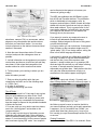
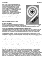
6 & $ 1 1 ( 5 6
6+257:$9(
+-( 3^(
9RO1R
2FWREHUHU
(VWDEOLVKHG
1!-)1!!#+
Kiwa now has the PRM or Pocket Regeneration
Module available for the Pocket Loop Antenna. The
PRM is an accessory for the Pocket Loop providing
regeneration from 530 kHz to >10 MHz. The
specification to 10 MHz is using the antenna coupler
slipped over the whip antenna. Regeneration to 17
MHz is possible using a direct cable connection to
the receiver.
Regeneration is an advanced feature of loop
antennas. As the regeneration is increased, the
bandwidth decreases and the receive gain
increases. An additional 18 to 24 dB gain can be
realized with no change in battery current. The
additional gain is helpful under weak signal
conditions. The improvement is selectivity is helpful
if adjacent frequency interference exists.
The PRM is a module that is physically attached to
the front vertical surface of the Pocket Loop. It is
installed between the Pocket Loop output and the
coupler or between the Pocket Loop and radio if a
direct cable connection is used.
Four controls operate the PRM:
Regeneration ON/OFF, High/Low Frequency switch.
Coarse Regeneration Tune, Fine Regeneration Tune
The Urban DX’er
The Urban DX’er is published
monthly through the
cooperative efforts of Bob
Kozlarek, WA2SQQ and
Charlie Hargrove, N2NOV
Any information contained is
considered public and can be
copied, distributed or
otherwise electronically
distributed provided that
proper credit is given..
Contributions of information
for future issues is always
welcomed and greatly
appreciated. Please send your
E mail to [email protected]..
PRM - Pocket
Regeneration Module
price is $48.00 (US)
Shipping and Handling
in North America is $4
Shipping and Handling
outside North America is
$7 We also have a 9
VDC (120 VAC) adaptor
for the Pocket Loop
Antenna. The price is
$10 plus $2 S&H in
North America
connects between the car radio and car antenna.
The coupler allows the
Pocket Loop to enhance weak signal reception. We
supply a 6 ft cable with the coupler so the Pocket
Loop can be placed on the dash or on top of the car
(not recommended while driving!). The coupler uses
standard (for most car radios) Motorola connectors.
It also includes a switch to bypass the coupler for FM
reception. Signals that aren’t even heard using the
car radio antenna will "jump out" using the Pocket
Loop and PRM! Pocket Loop Car Radio Coupler
price $35.00 Shipping and Handling for North
America $4 Shipping and Handling outside North
America $7
For more information contact Kiwa at:
[email protected] or http://www.wolfe.net/~kiwa
Sales Orders: 1-800-398-1146
Technical Information 509-453-5492
Kiwa Electronics
612 South 14th Ave.
Yakima WA 98902 USA
++++%)
Once upon a time you could hear an AM broadcast
station and consider it a sure bet that a reception
would bring a QSL card. That was than and this is
today - a time of budget cuts and stations that lease
engineers. I though it might make for an interesting
article to outline the procedure for submitting a
reception report and discuss some tips for increasing
your chances to get that coveted QSL card.
The Basic Report
While styles vary, I’ve had good results formatting
my reports in the form of a personal letter. The letter
should contain the following information, not
necessarily in this order.
1. Date and time of reception. (Local time and
“Zulu”)
2. Frequency you received them on.
DX from your car radio
using the Pocket Loop
Car Radio Coupler! Kiwa
also has a new coupler
for the Pocket Loop that
3. Specific details that should include names of local
P2FWREHU
7KH8UEDQ';·HU
can be directed to that person to increase your
chances of getting a reply!
The NRC also publishes their AM Radio Log that
lists all US and Canadian stations. The publication
which is distributed as loose pages sorts by
frequency and call letters. Station formats and other
details are included, facts that can help you identify
those weak stations. This is a great source for the
exact station address. If all else fails, you can take
your chances and address it to the stations call
letters @ the city the announce.
CCR - Turks & Caicos Island
advertisers, names of DJ’s or announcers, station
slogans or any other details that would convince
them that you heard their station. You can also
include comments on the stations format and local
weather if discussed.
4. Note the exact times when station ID’s were
received, and quote the verbiage as close as
possible.
5. Include information on the equipment you used to
receive them and be sure to tell them how well they
were heard. If their signal had competition from
another station be sure to mention that station.
6. Tell the person you’re writing to where you are
located
and a little about yourself.
7. End your letter by politely askin that your
reception be verified in one of the following ways.
a - A QSL Card
b- A letter of verification
c- signing and returning your letter
Tips & Tricks
So who do you send it to? Years ago it was a given
that you would address your letter to the “Chief
Engineer.” Major station still employ a person with
that title, usually very overworked and sometimes
less than eager to respond to the probable hundreds
of letters he receives.
If it’s a rare catch you may wish to send two letters,
one to the “chief engineer” and another to the
“program director.”
If you’re really into this facet of the hobby you can
subscribe to the National Radio Clubs newsletter
which is published weekly during the fall / winter DX
season. In most issues they list the names of people
who have been signing QSL cards. Your reception
If you expect to receive any response be sure to
include a self addressed stamped business
envelope. Station budgets for this sort of thing went
out with the holla hoop!
For foreign station you can include two *International
Reply Coupons or the somewhat simpler one US
“green stamp” ($1) If it’s a foreign station, writing the
letter in their native language also helps.
I also make it a point to say a little about myself like
how long I’ve been DX’ing the AM broadcast band
and the fact that I’m an active amateur radio
operator. I usually include one of my amateur QSL
cards and sign the card with my call letters following
my name. In several cases the person who
responded was a fellow ham. I really believe that this
can make the difference between a reply or a
contribution to the stations paper recycling bin!
Follow Ups
Mail off your report and sit back. I’ll usually wait
about 30 days before I send off a follow up report. In
KSL Salt Lake City - 1968
the follow up report be sure to mention that this is
your second attempt and why you’d really appreciate
a response - it’s my first station from Florida...you
get the idea! How many times you try is up to you,
but I usually give up at three attempts unless it’s truly
a rare one.
Closing Comments
I’ve included a few of the QSL’s I’ve received. Some
P2FWREHU
7KH8UEDQ';·HU
aren’t so rare, but many of them were among the
first I received almost 30 years ago! Most recently, I
received a QSL from RCN in Bogota, Colombia.
RCN is on 770 khz and not normally able to be
received. WABC’s chief engineer alerted me to the
fact that they would be off the air and I caught them
while WABC was silent. I received the letter,
refrigerator magnet, and station schedule via
registered mail from Columbia! It was accompanied
by a personal letter from the stations engineer
expressing delight as mine was the first letter he
ever received from New York! Considering the
prompt response, I took the time to send him a letter
and explain that WABC seldom leaves the air and
this rare opportunity came just once in 8 years!
(*
($," "3^ So What is BCB DX’ing?
BCB DX’ing is the Attempt to listen to AM broadcast stations
outside
CBW Winnipeg
your normal listening area. The broadcast band is defined as 530 1700
kHz. Please note that the top end of the broadcast band was recently expanded from 1600 to 1700 kHz.
OK, but what equipment will I need to enter this aspect of the radio hobby?
The greatest thing about BCB DX’ing is that you already have everything you’ll need to get started. Any AM
radio is all that’s needed. Given the fact that all receiver designs aren’t created equal, obviously some will
perform better than others. Here’s a few things to look for when selecting a good radio you already own.
Loopstick Antennas: Generally, the longer the internal antenna, the better they’ll work. Also, as the length
increases, so too will the null of the ends of the antenna. These nulls are used to selectively tune out stronger
stations, often allowing you to hear weaker stations. AM/FM/Cassette type “boom boxes” are a great choice
since they’re portable. Even better are some of the older car radios. These radios used an IF of 262.5 kHz and
are generally more selective.
Analog Tuning: Newer digitally synthesized digital readout radios may look high tech, but they tend to be much
noisier. Experience has shown that the older variable capacitor, dial cord variety radios perform much better.
Power Source: Since much of the noise we receive originates from AC power lines, opt for battery powered
receivers when possible. Here’s an interesting point to keep in the back of your mind - Many AM/FM radios
use the AC line cord and your house wiring as an antenna. This accounts for slightly better reception when
using the AC line cord on AC/DC receivers. Play it by ear and see if the extra signal strength outweighs the
extra noise.
Can I improve the reception by adding an external antenna.
Generally yes, but sometimes external antennas may actually decrease the performance of your station,
here’s why. Most AM radios won’t have an external antenna connection. Connecting an external antenna
internally will generally result in a massive overload of the front end causing images, hetrodynes, and a
general deterioration in overall receiver performance. If your receiver offers an external connection, by all
means go ahead and try some sort of a long wire antenna. Here’s a trick you can try with virtually any portable
radio. Wrap 5-10 turns of insulated hookup wire around your radio and connect the end of this wire to your
external antenna. By inductively coupling the antenna in this way, the chance of overload is greatly reduced
and it often will improve reception. Experiment, by winding the wire around the receivers width, length or girth.
P2FWREHU
7KH8UEDQ';·HU
Depending on the position of the receivers internal antenna, one method may perform better than others.
When is the best time to listen?
Propagation on the AM broadcast band is very similar to 160M. By the calendar, the winter months from
December through February are by far the best as atmospheric noise will be very low. The summer months
with lightning storms and natural atmospheric noise will definitely limit your BCB DX’ing! In general, long
distance reception will be present during periods of darkness and usually exhibit a short time enhancement for
the period beginning about thirty minutes preceding local sunrise and sunset to as much as 30 minutes past
these events. DX’ers often refer to this period as “gray line”. It was during these times when I’ve logged some
of my best catches. During this period, pick a frequency that doesn’t have a dominant station and listen as the
propagation rapidly changes. Often, you’ll hear several stations in the span of 20-30 minutes. If you don’t own
a small cassette recorder, invest in one. Being able to go back and review weak signals is a great help.
So I’ve heard a station but I wasn’t able to get a station ID. Is there any way assist me to identify the
station.
The National Radio Club publishes one of the best AM station directories I’ve seen. Published yearly, it lists all
stations in the U.S. and Canada, sorted by call letters, state, and frequency. In addition, the power, radiation
pattern, station address and format are listed for each station. Often, you can identify a station much easier if
we know the format. Station ID’s are usually given on the hour and every 15 minutes at 15, 30, 45 past the
hour. The NRC log is available from the National Radio Club.
So it would seem that the powerful 50kw stations are easy to hear, but how do you log the rare ones?
In a word, persistence pays off, but there are some tricks! The National Radio club arranges several “DX
Tests” each month. Basically, here’s how they work. The NRC contacts a specific station and arranges for
them to allocate a 15-30 minute broadcast where a unique style of music is played - usually marching music or
polka’s. In addition, the station will identify itself frequently, often using morse code. In doing so, their signal
can be singled out of the noise much easier. It’s also not uncommon for these stations to use omni-directional
radiation patterns that would normally be used only during daylight hours. Stronger stations on the frequency
may also cooperate and go off the air during the DX test. Despite the intense negotiations that must take
place to arrange these DX tests, the NRC usually has 5-10 per month during the BCB DX season that runs
from November through March. While many old timers to this aspect of the hobby regard this as cheating,
most see it no different than making a schedule on the HF bands to work a rare DX station.
Some Closing Comments
During the 1960's and 1970's it was customary for many stations to go off the air late Sunday night into
Monday morning. These were great opportunities to log stations on frequencies that were normally used by
local stations. Improved technology now has solid state transmitters replacing the old tube transmitters. These
new designs are virtually maintenance free and the need to go off the air is no longer there. Also, keep in mind
that air time is very valuable in most metropolitan areas. Being off the air for only 15-30 minutes could result in
the loss of $100,000 or more! In this area we are fortunate
in the respect that most of the NY metro area stations are
in Bergen County area. Many of the chief engineers are
fellow hams and we BCB DX’ers are often informed of
scheduled maintenance that requires a station to leave the
air.
*6,
*"(,
535 RVC
Caicos
600 WICC
650 WSM
670 WMAQ
680 WRKO
(
Radio Vision Christiana, Turks &
Bridgeport, CT
Nashville, TN
Chicago, IL
Boston, MA
WBT 1968
P2FWREHU
700
740
750
760
780
800
800
810
830
840
850
870
900
1000
1020
1020
1040
1080
1090
1100
1110
WLW
CBL
WSB
WJR
WBBM
CKLW
PJB
WGY
WCCO
WHAS
WHDH
WWL
CHML
WLUP
KDKA
* CCR
WHO
WTIC
WBAL
WWWE
WBT
CKTY
1160 WJJD
1500 WTOP
7KH8UEDQ';·HU
Cincinnati, OH
Toronto, Canada
Atlanta, GA
Detroit, MI
Chicago, IL
Windsor, Ontario (Talk Format)
Bonaire, Netherlands Antilles (Religious Format)
Schenectady, NY
Minneapolis, MN
Louisville, KY
Boston, MA
New Orleans, LA
Hamilton, Ontario
Chicago, IL (ex WCCO)
Pittsburgh, PA
Caribbean Christian Radio - Turks & Caicos Islands
Des Moines, IA
Hartford, CT
Baltimore, MD
Cleveland, OH (ID’s as “3WE”)
Charlotte, NC (Talk Format)
Sarnia, Ontario (C&W Format)
Chicago, IL
Washington DC
NFM DISCRIMINATOR CHIPS - BASEBAND AUDIO - SQUELCH GATE DATA
There is a growing interest in tapping the baseband audio out of various scanners for decoding of a variety of
esoteric
signals, including CTCSS, SCA, FSK, RTTY, FAX, etc. By and large, such signals cannot be taken from
TAPE REC jacks, headphone jacks, and EXT SPEAKER jacks because of the voice-band filtering that is done
between the signal source and these output jacks.
Therefore, it is necessary to tap the "baseband audio" directly at the output of the discriminator chip for your
scanner. Table 1 shows a list of scanners, the discriminator chip(s) used in the scanner, circuit symbols of
those chips, and three pins of general interest on the chips: RF-Input, Scan Control, and, of course, the
baseband audio (discriminator output) pin.
Even though your scanner may not be listed below, try to find its discriminator chip, and chances are it will be
listed with
one or more scanners below, the pins of which will be the same for your unlisted scanner! Corrections and
additions to this list are requested. See my mail and other addresses at the end of this file.
For hookup information, see just below Table 1.
TABLE 1: SCANNER DISCRIMINATOR CHIP PINS OF INTEREST
SCANNER
NFM IC TYPE
PART ID
RF IN PIN
SCAN PIN #
AR-1000
AR-2002
AR-2500
MPS5071
TA-7787AF
MC-3357P IC-4
TA-7761P
n/a
IC-4
16
IC-13
16
16
13
16
13
none
9
9
BASEBAND AUDIO
9
9
?
P2FWREHU
AR-3000
MC-3357P
AR-800
MC-3361NIC-200
AR-900
MC-3361N
AR-950
MC-3361N
AR-8000 NFM
TK10489M or-85M U1
AR-8000 WFM/AM TA7792F
BC-100XL
MC-3359P IC-1
BC-100XLT
TK-10421M-2
BC-140XLT
MC-3359P IC-1
BC-200XLT
TK-10421M-2
BC-205XLT
TK-10421M-2
BC-250
?
BC-2500XLT
TK-10930VTL
BC-3000 NFM/AM TK-10930V
BC-3000 WFM
TK-10489M
BC-350A
NJM-3359D-A
BC-400XLT
NJM-3359D-A
BC-560XLT
NJM-3359D-A
BC-700A
NJM-3359D-A
BC-760XLT
NJM-3359D-A
BC-800XLT
MC-3359P IC-1
BC-8500XLT
MC-3361BP
BC-855XLT
TK-10421M-2
BC-890XLT
NJM-3359D-A
BC-950XLT
NJM-3359D-A
HX-1000
TK-10420
MR-8100
NJM-3359D-A
MX-5000
MC-3357P IC-4
MX-7000
MC-3357P IC-4
PRO-2002
MC-3357P
PRO-2003
MC-3357P
PRO-2004 NFM/AM TK-10420
PRO-2004 WFM
KB4419A
PRO-2005 NFM/AM TK-10420
PRO-2005 WFM
KA2243N/HA12413
PRO-2006 NFM/AM TK-10420
PRO-2006 WFM
KA2243N/HA12413
PRO-2011
TK-10420
PRO-2020
MC-3357P IC-101
PRO-2021
TK-10420
PRO-2022
MC-3361NIC-1
PRO-2023
NJM-3359D-A
PRO-2024
MC-3361NIC-2
PRO-2025
NJM-3359D-A
PRO-2026
NJM-3359D-A
PRO-2027
MC-3361NIC-2
PRO-2028
NJM-3359D-A
PRO-2030
NJM-3359D-A
PRO-2035 NFM/AM TK-10420
PRO-2035 WFM
KA2243N/HA12413
PRO-2042 NFM/AM TK-10420
PRO-2042 WFM
KA2243N/HA12413
PRO-23
MC-3361BD
PRO-26 NFM/AM
TK-10930V
PRO-26 WFM
TK-10489M
PRO-31
TK-10420
PRO-32
TK-10420
PRO-34
TK-10420
PRO-35
TK-10421M-2
7KH8UEDQ';·HU
?
16
IC-201
IC-201
20
U3
18
IC-401
18
IC-401
IC-401
IC-3
IC-201
IC-202
IC-203
IC-3
IC-1
IC-1
IC-3
IC-2
18
IC-9
IC-401
IC-3
IC-2
U-201
IC-3
16
16
IC-101
IC-104
IC-2
IC-1
IC-2
IC-1
IC-2
IC-1
IC-1
16
IC-2
16
?
16
IC-1
IC-7
16
IC-2
IC-3
IC-2
IC-1
IC-2
IC-1
IC-1
IC-14
IC-16
IC-1
IC-101
IC-101
IC-401
16
13
16
16
16-17
16
15
20
15
20
20
16
24
24
20
18
18
18
18
18
15
16
20
18
18
16
18
13
13
16
16
16
1
16
1
16
1
16
13
16
13
18
13
18
18
13
18
18
16
1
16
1
16
24
20
16
16
16
20
13
9
13
13
11
8
10
16
10 *
16
16
13
12-FM 13-AM
12-NFM 13-AM
16-17
15
15
15
15
15
10
13
16
15
15
13
15
9
9
13
13
13
6 (TP3)
13
10 (TP1)
13
10 (TP1)
13
9
13
9
15
9
15
15
9
15
15
13
10 (TP1)
13
10 (TP1)
13
12-NFM 13-AM
16-17
13
13
13
16
9
9
9
11
11
11
9
11
10
10
10
10
10
9
11
10
10
9
10
9
9
9 (TP4)
9 (TP2)
9 (TP2)
9
9
10
10
10
10
10
9 (TP2)
9 (TP2)
9
11
9
9
9
11
P2FWREHU
PRO-36
TK-10420
IC-101
16
13
PRO-37
TK-10420
IC-101
16
13
PRO-38
MC-3359P IC-1
18
15
10
PRO-39
MC-3361NIC-201
16
13
9
PRO-41
MC-3359P IC-1
18
15
10
PRO-42
MC-3361NIC-2
16
13
9
PRO-43
TK-10427/-10420
IC-301
16
13
PRO-44
MC-3361NIC-201
16
13
9
PRO-46
TK-10421M-3LT
IC-401
20
16
PRO-51
MC-3361BD
IC-1
16
13
PRO-60
?
IC-301
16
13
Icom R-1 NFM
TK-10487 DET-A
IC-1
20
Q1
Icom R-1 WFM
TA-7787AF DET-B
IC-1
16
7
Icom R7100
Said to be "top of R230 on the top of main PCB" *
R-1600
NJM-3359D-A
IC-2
18
15
R-4030
TK-10421M-2
IC-401
20
16
SR-15
TK-10421D-2
IC-1
16
13
StandardCCR708A TK-10420D
Q602
16
13
TurboScan 2
3130-6056-502
U-201
18
?
Yaesu FRG-9600
MC-3357P ?
16
13
9
*
====================================================================
* Not personally verified by me
7KH8UEDQ';·HU
9
9 (TP103)
9
11
9
9
11
9
10
11
9
9
*
10 or 16
HOOKUP PROCEDURE
If you need the raw Discriminator baseband audio signal for external purposes, the best way to access it is via
a jack installed in a convenient, unobtrusive location on the scanner.
1. Install an RCA or other jack in a desired place on the scanner’s external case, typically the rear panel.
2. Connect the shell or outer frame part of the jack to scanner chassis ground.
3. Connect the (+) leg of a 2.2-uF tantalum capacitor to the Discriminator output Pin. (Capacitor should be
tantalum, but can vary in value from 1.0-uF to 10-uF at a voltage rating of 25-50vdc.)
Pin ______shield____________>
o---|(-------------------------o
+ center conductor
4.Connect the center conductor of a shielded coax (RG-174, etc) or shielded mic cable to the (-) leg of the
capacitor.
5.Connect the shield of the cable at this end to a nearby PCB ground trace or spot.
6.Connect the center conductor of the other end of this cable to the center or hot lug of the jack.
7.Connect the shield of the cable at that end to the ground lug of the jack.
8.Fabricate or buy a shielded patch cable with one end to mate with the new jack on the rear of the scanner at
that end....and the other end to mate with whatever jack is on the tape recorder, processor, decoder, or
whatever device is to be connected at the other end.
SCAN CONTROL" AND SQUELCH PIN DATA FOR UNIDEN SCANNERS AND REALISTICS MADE BY UNIDEN
Uniden does their darndest to make it difficult to hack their scanners. You guys have some work to do. Here’s
P2FWREHU
7KH8UEDQ';·HU
the deal: Even though all NFM discriminator chips have a SCAN CONTROL pin, Uniden doesn’t always use it!
Some Uniden scanners have a separate Squelch circuit with the SCAN CONTROL pin on the discriminator
unused! You have to find the real Squelch circuit, and then determine the Logic for that circuit. It’s easy, but
differs from one scanner to the next, and I can’t cover them all. I need your help.
See Table 2 below for a good reference. By and large, those with scanners of Uniden origin have
to tackle the preliminaries in this fashion:
1. Locate the NFM Discriminator chip - you will find the Audio pin from Table 1. It remains valid.
2. Determine if the SCAN CONTROL pin on that chip is used. (Follow its trace out on the PCB)
A. If so, then determine the logic order. If the SCAN CONTROL pin is used, then we can use it!
B. If the SCAN CONTROL pin is not used, then locate the real Squelch circuit. The schematic and block
diagrams in the service manual will be helpful. Uniden uses chips like NJM2902, NJM2904 & NJM3403 to
generate Squelch logic. Use your voltmeter to find a spot where the Squelch logic is 0v and 5 or 8v, depending
on the setting of the Squelch control. Table 2 shows details for those Uniden-made scanners with which I am
familiar.
TABLE 2 - UNIDEN SQUELCH CHIPS
Scanner
SQ Chip
CktSym
Pin
PRO-26
BC-890XLT
BC-2500XLT
BC-8500XLT
BC-350A
BC-700A
PRO-51
PRO-2030
NJM3403AV
NJM2902N
NJM3403AV
NJM2904M
NJM2904S
NJM2904D
NJM2902V
NJM2904S
IC-17
IC-8
IC-204
IC-8
IC-552
IC-11
IC-4
IC-10
14
7
14
7
8
7
8
8
Computer Controlled Scanning with Optoelectronic’s OptoScan and Probe V3
by Perry Joseph
My thanks to all who took the time to review Probe V3.0 in the last issue of "The Urban DX’er". Special thanks
to Bob Kozlarek for inviting me to provide some feedback on that review and to provide additional notes on the
OptoScan and Probe V3.
First let me provide some background on myself. I am 43 years old and live in St. Louis, Missouri. I have been
developing software for about 10 years. The bulk of my work is for small companies and focuses primarily on
database management and support. Long before my involvement in software development, and before the
introduction of the personal computer, I have enjoyed the hobby of "scanning" starting with an early Bearcat
crystal controlled radio. My primary pleasure is listening to public safety. I also have a ham license and enjoy
talking with friends on the 2 meter band. I belong to a local scanner club in St. Louis called SABRE (St. Louis
All Band Radio Enthusiasts) and am the volunteer Editor for our newsletter, appropriately named "SABRE
News".
Over the years, there have been a few milestones in my hobby of scanning. The first major milestone for me
was the introduction of programmable scanners. What a delight that was; no more having to procure, install
and swap crystals! The next major milestone was the introduction of the personal computer. Instead of having
to keep copious hand written notes of frequencies and users, I could keep my volume of notes organized in a
database program. I have always considered scanning to be a data driven hobby and the marriage of
P2FWREHU
7KH8UEDQ';·HU
computers with this hobby seemed only natural. And the latest milestone was the introduction of devices which
allowed me to connect my computer to my scanner. Not only could I link the data in the computer to my
scanner, I could now do things the scanner’s processor was incapable of.
Early products to computerized scanning were somewhat primitive but welcome nonetheless. Most of the
function was to extend the keyboard functions of the scanner to the computer. I’ve seen these devices
sometimes referred to as "button pushers". In some cases, they do to allow for coupling frequency numbers to
the names of the frequency users so they could be viewed on the computer monitor. It’s a great feature
not having to look up a frequency number on paper to figure out who is using a frequency, however some of
the newer scanners now offer this as a stock feature. Other options were also available such as the logging
of active frequencies and the ability to upload or download frequency data to and from the scanner which
tends to be faster than having to program a scanner by hand.
While the industry has not developed any certain terminology for describing the differences for these new
technologies, I have invented a few of my own definitions. I define the upload / download of frequency
data to and from the scanner as "computer assisted", and for those devices which take complete control over
the scanner, I define them as "computer controlled". Optoelectronic’s OptoScan fits this term "computer
controlled" to a tee. In fact, the OptoScan goes a number of steps further by providing additional functions
which are not found on the stock scanners it was designed for (Radio Shack’s PRO-2005, PRO-2006,
PRO- 2035 and PRO-2042) such as CTCSS / DCS (PL) tone control and readout, DTMF decoding, signal
strength readout and increased scanning speed. One of the greatest things about true computer controlled
scanning is the virtually unlimited bank and channel capacity. With Probe, you can have up to 99 banks, each
bank can contain up to 1000 frequencies. These 99 banks are held in a "group", and you can have up
to 4000 groups (only one group can be scanned at a time). Needless to say, capacity is no longer a concern.
Having seen other products which offered the ability to connect the computer to the scanner, I was most
impressed with the OptoScan. In my opinion, it was well engineered and wonderfully thought out. More
importantly, the OptoScan allowed the software developer to take complete control of the scanner’s functions.
Previous products simply allowed you to send commands to the scanner, and in some cases, read
back a limited amount of information from it. The OptoScan provided feedback on the actual status of the
scanner, which in layman’s terms, provides virtually error free, fast and dependable operations.
While some have been miffed at Optoelectronic’s omission to provide software and software assistance for
their product, I was quite pleased with their policy of being "software neutral". Not because it presented
opportunities for software developers such as myself, but as a hobbyist, it meant developers would be enticed
to fully usurp the OptoScan’s capabilities without having to compete head on with the manufacturer.
This is very important if one understands how very limited the market for this technology is, and as a result,
how difficult it is to recoup development costs. In other words, we could have been easily stuck with
one piece of software provided by Optoelectronics to run the OptoScan rather than having the many software
options from a variety of vendors we now have. This variety has led to many new and innovative features
which otherwise can’t be found on the stock scanner or in other computer controlled scanning devices where
the manufacturer has kept a lock on the protocol thus limiting new innovations and proliferation of
"computer controlled scanning" in general.
Probe V3.0:
To understand Probe V3.0 and its purpose, it is important to understand the primary objectives for developing
it. Over the years of developing software, I’ve learned there is no such thing as pleasing everyone. Of course,
that doesn’t mean I don’t try. But I’ve learned it’s important to have objectives and to define your niche. When
folks ask me which is the best software for the OptoScan, my response is "it depends on what you’re trying to
do". Another way of putting it is some folks like Chevies and others like Fords. With Probe, there were specific
objectives involved. To develop these objectives, I spent months working with my friends at SABRE and with
others around the country who shared my interests in computer controlled scanning. Here is a short summary
P2FWREHU
7KH8UEDQ';·HU
of some of the primary objectives:
The first objective was to take full advantage of the capabilities of the OptoScan. That would seem only
natural, but because of the uniqueness of the OptoScan interface, it meant the market for Probe would be
limited to OptoScan users making it difficult to recover development costs. To overcome this hurdle, and to
keep the price of Probe competitive, a different marketing strategy was developed. Probe would be sold by
mail order only to eliminate the expense of staffing a telephone. Support would be substituted with electronic
mail, thorough documentation, and a very stable and tested program. Advertising would be minimal and
supplemented by endorsements from satisfied users and product reviews. And no time would be spent
developing "demo" programs. In short, the majority of my time would be devoted to trying to make
Probe the best software for the OptoScannist.
The second objective was scanning speed. OptoScan’s unique and exclusive "pipeline tuning" provides a
major increase in scanning speed over slower conventional means used by most other OptoScan programs.
Pipeline tuning also requires a substantial hurdle in programming. We wanted the fastest possible scanning
speed, and as a result, spent over three months scratch building Probe’s engine before adding features,
functions and screens.
The third objective was to make Probe easy to use and versatile while providing as many features as possible.
It is a delicate balance to develop a program for both novices and power users. As a result, Probe
can be run on the lowliest of computers without any sacrifices to features and performance. Probe uses a true
dBASE engine allowing the user to work directly with a dBASE file, and uses a data structure
modeled from the FCC databases.
The fourth and final objective was to provide features specifically for the scanning enthusiast. The other
software packages had their roots in shortwave and seemed to miss many of the finer points of scanning. One
of these points is having immediate control over your scanner which can make a major difference when your
are trying to follow fast breaking action.
Some of Probe’s Unique Features:
Probe is a DOS based program and runs on virtually any computer capable of running at least DOS V3.1.
Unlike other programs (which I fondly refer to as "bloatware"; no offense to competing products) which can
only be run on more expensive Window’s based computers, Probe can be run on virtually any IBM compatible
computer including Hewlett Packard’s HP200 palmtop computer. Many Probe users find it more efficient and
practical to run Probe on a computer dedicated to their scanner. In most cases, these older computers can be
purchased used for less than the price of the OptoScan, or Probe for that matter. In fact, we’re now starting to
see some of the older laptops showing up at giveaway prices. These laptops make an excellent addition to the
monitoring hobbyist for all sorts of uses. But that doesn’t mean you can’t run Probe on a Window’s based
computer either; it works fine there as well. With Probe, you can have your cake and eat it too. I believe in
versatility even if that means sacrificing "pretty graphics" which can require additional,
and many times, substantial computer resources which can cut into processing time and otherwise be used to
expedite an important function required to stay on top of fast breaking action. In short, Probe may not
be pretty to some, but it is efficient and functional.
Probe has a number of unique functions which go far beyond the usual features provided by computer
controlled scanning found in most software products; usual features including displaying a name of the
frequency’s user and logging the date and time of activity. An example of this is Probe’s exclusive
"SmartScan".
SmartScan allows you to focus in on fast breaking action. Key frequencies are assigned as triggers. When
activity is detected on one of these key frequencies, PROBE activates an assigned bank of
frequencies, called a "SmartBank", for a specified amount of dwell time. A SmartBank can be any bank of a
few frequencies or as many as 1000. For each key frequency, you can choose whether the SmartBank is the
P2FWREHU
7KH8UEDQ';·HU
only bank scanned (exclusive mode), or is added to current banks scanned (non-exclusive mode). The length
of dwell time spent in either mode can be tailored to your own situation. If activity is detected within the
SmartBank of frequencies during the dwell time, the dwell timer is reset so you can continue to monitor the
action.
For example, you can designate the air emergency frequency 121.5000 as a key frequency. When it becomes
active, you can have your scanner stop everything else it is doing and exclusively scan just those frequencies
related to the air emergency frequency, like the local tower, ground control, rescue squad and air port security,
or you can include them with the other frequencies being scanned in what we call the
non-exclusive mode. Once the action settles down, normal scanning resumes. And this is just one of many
uses for SmartScan.
Another unique feature to Probe is "Hyperbanks". With just one simple keystroke, this feature immediately
activates any combination of 99 scanning banks. Each of the ten available Hyperbanks can be customized
with a description so you can easily remember what each Hyperbank is designed to monitor. Hyperbanks
allows the OptoScan to become a tactical system, where it is quickly and easily reconfigured to the needs of
the moment. Rather than switching to the a "banks" screen, deactivating and then activating the appropriate
banks, you only have to press one function key and go. Thus, with the ten function keys having a separate
banks configuration, it is like having ten scanners available, all at the touch of one key.
Say you have any number of banks setup to suit your interests. There’s a bank for fire, another for media and
another for local government. You can configure the "F1" key to activate these three banks and describe it
as "Working Fire". Other banks could include your favorite frequency banks such as federal law enforcement,
local and state law enforcement. Configure the "F10" key with these banks and describe it as Favorite
Frequencies . When a major event occurs, press "F1" and the fire, media and local government banks are
immediately activated. When everything is finished, press "F10" and you are back to your normal
configuration.
These are just a couple of the many functions Probe implements which demonstrate what true computer
controlled scanning can do for the scannist. We’re able to provide functions which go beyond the stock
scanners capabilities. And it doesn’t stop there. One of the more simple advantages of computer controlled
scanning is being able to trade frequency data with one another. A number of my fellow scannists who
belong to our local club and have Probe make it a regular habit of trading floppy disks at meetings. Rather
than having to take notes and go back to our scanners to reprogram them, we simply load the disk into
the program and voila! It’s kind of like trading scanners amongst ourselves. There’s also the ability to share
"universal" and out-of-town frequency data. Last time I attended the Dayton Hamfest, Dave Marshall,
Editor of the All Ohio Scanner Club Journal, e-mailed me a copy of his frequency data. And finally, Probe has
the ability to import frequency data from PerCon’s FCC database. You can import in a subset of frequency
data for your monitoring position using what we call a "radius search". You specify your latitude, longitude and
the mileage of the radius you’re interested in. Probe automatically breaks down the frequency data
by bank; each bank containing a specific service group and a description of the service. Needless to say, any
of this sure beats a programming the scanner by hand.
Additional notes and corrections to the last review:
Probe requires 640K conventional memory, 512K free; not the 8MB suggested in the previous article. To use
the radio normally does not require a physical disconnect of the computer; one needs simply to quit
the scanning process in the software.
The regular price for Probe is $129.95 + $7.95 for S/H. Subscribers of "The Urban DX’er" can purchase
Probe for a limited time for $89.95 + $7.95 S/H by mentioning this
article.
P2FWREHU
7KH8UEDQ';·HU
Orders must be postmarked by November 22nd, 1997. MC / Visa / check / money orders accepted. Orders
can be sent to DataFile, Inc., PO Box 20111, St. Louis, MO, 63123. Additional information and / or questions
regarding Probe can also be directed to DataFile via email at [email protected]. There is a web page
which has information, screen shots, frequency files and additional documentation provided by a Probe
user, Steve Hancock, on his web page at http://home.ptd.net/~pro2006/probe.html. This web page is
primarily dedicated to those interested in the PRO-2006 (which would also cover the PRO-2005 and other
similar scanners) and has a wealth of information on it. Steve’s home page address for his "Monitoring Post" is
http://home.ptd.net/~pro2006 .
The OptoScan 456 works with Radio Shack’s PRO-2005, 2006. The OptoScan 535 works with Radio Shack’s
2035 and 2042. Optoelectronics reports the OptoScan has not been tested with the PRO-2045 reported in the
last article, and to my knowledge does not work with the PRO-2045. Perhaps this was a typo? (Oops - you
caught me! - Sorry about that) If in fact the OptoScan does work with the PRO-2045, I
would be most interested in hearing of this. There is also an OptoScan Lite which is less expensive than the
regular 456 and 535 and works with Radio Shack’s PRO-2005, 2006. The only difference between the Lite
version and the regular versions is it does not support signal strength readout, tone control or DTMF readout.
For additional information regarding the OptoScan, contact
Optoelectronics at 954-771-2050 or you can write them at 5821 NE 14th Ave., Ft. Lauderdale, FL, 33334.
Optoelectronics also has a web site at http://www.optoelectronics.com or you can email them at
<[email protected]>
While Roger expressed some concerns for the documentation, I would like to note I do provide support via
email virtually seven days a week. When you need support, you talk directly to the programmer. Try that with
Microsoft or most other software vendors. New purchasers of Probe are advised through a cover letter they
should read the documentation for Probe to get the most from it. It should also be noted the program was
intended to be easy-to-use and some previous experience with scanning was expected. For novice scannists,
Probe was designed to be grown into.
I read where the default colors of Probe were "hardly legible" and wonder whether a custom color file was
inadvertently included by Bob when he provided the evaluation software to Roger. The default color of Probe
for data text is bright white on black and the data descriptions are red on black. Probe also has an easy onebutton setting for black and white or amber monitors. I do agree with Roger regards the descriptions for
color selections, however given the input I’ve received on this issue to date, I haven’t received any specific
suggestions on how to better describe the colors selections. It’s important to note I am always am
interested in any suggestions on how to improve Probe. To a very large degree, feedback from Probe users is
what has made Probe the product it is today. In fact, I have kept a copy of the review done by Roger so I
may implement some of his suggestions in any potential revisions.
Regarding "no help" for Windows ’95 users, I will look to revise the documentation in the future to cover this
issue. In simple terms, run Probe as a DOS program in a Window’s window. There are no specific or
non-specific instructions or settings required beyond that. Anything beyond this information becomes Windows
specific, and as with DOS, is well beyond the scope or the Probe documentation and should be covered in the
operating system / computer hardware documentation.
In terms of instructions for "editing" the "CONFIG.SYS" file, Probe automatically checks the "CONFIG.SYS"
file upon startup. If it is incorrect, Probe advises you of this condition and will automatically make changes if
the user agrees to let the program do so. Again, if Bob provided Roger with previously installed copy of Probe,
this message may not appear. Another scenario is if Probe did not detect any requirement for changes, no
message would appear and the program works fine. The only real requirement Probe has for the
CONFIG.SYS file is "FILES=40" or more.
I somewhat agree with Bob’s comment on the "user’s interface screen should do something to appeal to and
enhance that imagination". With all due respect, Probe is meant to be a high speed interface, utility style
P2FWREHU
7KH8UEDQ';·HU
product; not a glitzy graphics program loaded with numerous windows and buttons, which in my terms, get in
the way of what we’re functionally trying to provide. It’s meant to be run on the older computers dedicated
to the scanner as many of us addicts have done. I have kept the code size to a minimum on purpose, for
reasons described earlier in this piece, and have made a serious attempt to provide all of the information
needed on one screen so one does not have to switch through multiple screens to figure out what is going on.
Frequency data and the various settings which effect the scanning process can be accessed directly from
the scanning screen. And note Probe’s small executable file size of less than 500K!
Again, my sincerest thanks to Bob, Roger and all the folks at "The Urban DX’er" for their review and for the
opportunity to talk about Probe. It’s a pleasure to work with folks who are dedicated to and enjoy the
world of monitoring.
5-)!
Charlie passes this info along that he received from N2OFN via an e mail posting.....
“Hi Charles, Sure I'll give you the frequencies for the private bus lines in NYC. They are rather easy to
follow on a regular scanner as there are only 5 frequencies used, and only the bus companies use them so
you don't have to weed out an oil co. making a delivery or a taxi being dispatched etc.... The companies on
this system, that is "owned" by NYC Dept. of Transportation are:
Green Bus Lines, Jamaica Bus, Queens Surface Corp., Triboro Coach, New York Bus Service, Command
Bus. I'm not sure but I think Liberty Lines and the Waterways Ferry buses are also on the system, but I never
hear them . I think they have their own radios that they use mostly. All of the above
companies are under the direction of the NYCDOT.
Repeater Output frequencies:
936.4875
936.4500
935.4875
935.4625
935.4500
I'm sure as you know, the input frequencies are minus 39 Mhz on this band. BTW...your call sounds
familiar...do you run the scanner net on Wed nite on MAARC? What repeaters do you use? I'm always
listening to my FT-50 when I drive my bus in Manhattan! Talk to you soon.
Editors Note: See, we never know who is listening!!
"* " ,*.... Just as I was finishing up this months newsletter, the phone rang - it was Dave,
WI2Q calling to alert me to the fact that the NJ State Police trunked system was humming with activity.
Tragically, a state trooper was shot and killed. I’ve never herard this much law enforcement mobilize so quickly
with at least three helicopters in the air within minutes. Much of the activity would not have been heard without
the Trunk Trackers!!