1
Previous Menu
INSTALLATION
INSTRUCTIONS
ViSTA
SECURITY SYSTEM
No. 4130XT
10/88
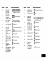
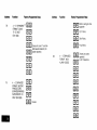
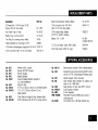
General Information
. . . . . . . . . . . . . . . . . . . . . . . . . . . . . . .
Remote Programming
and Control . . . . . . . . . . . . . . . . . . . .
Zone Types Available
for Selection
. . . . . . . . . . . . . . . . . . .
Functional
Description
of Zone Types . . . . . . . . . . . . . . . . .
Zone Expansion
. . . . . . . . . . . . . . . . . . . . . . . . . . . . . . . . . .
4-Digit Security Codes . . . . . . . . . . . . . . . . . . . . . . . . . . . . .
Wiring Connections
. . . . . . . . . . . . . . . . . . . . . . . . . . . . . . . .
Remote Keyswitch
Operation
and Wiring . . . . . . . . . . . . .
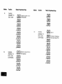
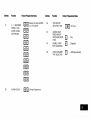
Optional
Remote Keypad Connection
(4131/4147)
. . . . .
Optional
Remote Console Connection
(4137/4157)
. . . .
installing
the Digital Communication
Interface
Board . . . . . .
installation
of No. 4152LMand
Wiring to No 4208 . . . . . . . .
Mounting
the 4130XT Control.
. . . . . . . . . . . . . . . . . . . . . . .
Surface Mounting
. . . . . . . . . . . . . . . . . . . . . . . . . . . . . . .
Flush Wall Mounting
. . . . . . . . . . . . . . . . . . . . . . . . . . . . .
Programming
the Security Control
. . . . . . . . . . . . . . . . . . . .
Factory Preset Values . . . . . . . . . . . . . . . . . . . . . . . . . . . .
Specific Address Programming
Instructions
. . . . . . . . . . .
Testing the System . . . . . . . . . . . . . . . . . . . . . . . . . . . . . . . .
Turning the System Overto
the User . . . . . . . . . . . . . . . . . .
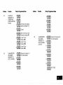
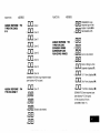
To the installer
. . . . . . . . . . . . . . . . . . . . . . . . . . . . . . . . . . .
Recalling
Alarm and Trouble Messages
. . . . . . . . . . . . . . . .
Replacing
Fuses on 4130XT Circuit Board . . . . . . . . . . . . . .
Replacement
Parts . . . . . . . . . . . . . . . . . . . . . . . . . . . . . . . .
Optional Accessories
. . . . . . . . . . . . . . . . . . . . . . . . . . . . . .
FCC Statement
. . . . . . . . . . . . . . . . . . . . . . . . . . . . . . . . . . .
Specifications
. . . . . . . . . . . . . . . . . . . . . . . . . . . . . . . . . . . .
4130XTSecurity
Control . . . . . . . . . . . . . . . . . . . . . . . . . .
4171XT Digital Communication
Interface Board . . . . . . . .
. . . . . . . . . . . . . . . .
. . . . . . . . . . . . . . . .
. . . . . . . . . . . . . . . .
. . . . . . . . . . . . . . . .
. . . . . . . . . . . . . . . .
. . . . . . . . . . . . . . . .
. . . . . . . . . . . . . . . .
. . . . . . . . . . . . . . . .
. . . . . . . . . . . . . . . .
. . . . . . . . . . . . . . . .
. . . . . . . . . . . . . . . .
. . . . . . . . . . . . . . . .
. . . . . . . . . . . . . . . .
. , . . . . . . . . . . . . . .
. . . . . . . . . . . . . . . .
. . . . . . . . . . . . . . . .
. . . . . . . . . . . . . . . .
. . . . . . . . . . . . . . . .
. . . . . . . . . . . . . . . .
. . . . . . . . . . . . . . . .
. . . . . . . . . . . . . . . .
. . . . . . . . . . . . . . . .
. . . . . . . . . . . . . . . .
. . . . . . . . . . . . . . . .
. . . . . . . . . . . . . . . .
. . . . . . . . . . . . . . . .
. . . . . . . . . . . . . . . .
. . . . . . . . . . . . . . . .
. . . . . . . . . . . . . . . .
.
.
.
.
.
.
.
.
.
.
.
.
.
.
.
.
.
.
.
.
.
.
.
.
.
.
.
.
.
.
.
.
.
.
.
.
.
.
.
.
.
.
.
.
.
.
.
.
.
.
.
.
.
.
.
.
.
.
. .
. .
. .
. .
. .
. .
. .
. .
. .
. .
. .
. .
. .
. .
. .
. .
. .
. .
. .
. .
. .
. .
. .
. .
. .
. .
. .
. .
. .
. .
. .
. .
. .
. .
. .
. .
. .
. .
. .
. .
. .
. .
. .
. .
. .
. .
. .
..
. .
. .
. .
. .
. .
. .
. .
. .
. .
. .
.
.
.
.
.
.
.
.
.
.
.
.
.
.
.
.
.
.
.
.
.
.
.
.
.
.
.
.
.
.
.
.
.
.
.
.
.
.
.
.
.
.
.
.
.
.
.
.
.
.
.
.
.
.
.
.
.
.
.
.
.
.
.
.
.
.
.
.
.
.
.
.
.
.
.
.
.
.
.
.
.
.
.
.
.
.
.
.
.
.
.
.
.
.
.
.
.
.
.
.
.
.
.
.
.
.
.
.
.
.
.
.
.
.
.
.
. .
. .
. .
. .
. .
. .
. .
. .
. .
. .
. .
. .
. .
. .
. .
. .
. .
. .
. .
. .
. .
. .
. .
. .
. .
. .
. .
. .
. .
. . . . . . . . . .
. . . . . . . . . .
. . . . . . . . . .
. . . . . . . . . .
. . . . . . . . . .
...,..............,12
. . . . . . . . . .
. . . . . . . . . .
. . . . . . . . . .
. . . . . . . . . .
. . . . .. . . . .
. . . . . . . . . .
. . . . . . . . . .
. . . , . . . . ,.
. . . . . . . . . .
. . . . . . . . . .
. . . . . . . . . .
. . . . . . . . . .
. . . . . . . . . .
. . . . . . . . . .
. . . . . . . . . .
. . . . . . . . . .
. . . . . . . . . .
. . . . . . . . . .
. . . . . . . . . .
. . . . . . . . . .
. . . . ,. . . . .
. . . . . . . . . .
. . . . . . . . . .
.
.
.
.
.
.
.
.
.
.
.
.
.
.
.
.
.
.
.
.
.
.
.
.
.
.
.
.
.
.
. ...4
. ...5
. ...7
. ...8
...12
.
.
.
.
.
.
.
.
.
.
.
.
.
.
.
.
.
.
.
.
.
.
.
.
.
.
.
.
.
.
.
.
.
.
.
.
.
.
.
.
.
.
.
.
.
.
.
.
.
.
.
.
.
.
.
.
.
.
.
.
.
.
.
.
.
.
.
.
.
.
.
.
.
.
.
.
.
.
.
.
.
.
.
.
.
.
.
.
.
.
.
.
.
.
.
.
.
.
.
.
.
.
.
.
.
.
.
.
.
.
.
.
.
.
.
.
.
.
.
.
.
.
.
.
.
.
.
.
.
.
.
.
.
.
.
.
.
.
...16
...18
...18
. . . 19
...20
...21
...22
. . , 22
...24
...28
...29
...40
...70
...71
...71
...71
...72
...73
...73
...74
. . . 75
. . . 75
...75
4137 Remote Console . . . .
4157 Remote Console . . . .
4131/4147RemoteKeypad...
4152LM Loop Module . . . .
42088-Zone
Expander . . .
Appendix
A, Cabinet Mounting..
. . . . .
. . . . .
.
. . . . .
. . . . .
. .
.
.
.
.
.
.
.
.
.
.
.
.
.
.
.
.
.
.
.
.
.
.
.
.
.
.
.
.
.
.
.
.
.
.
.
.
.
.
.
.
.
.
.
.
.
.
.
.
.
.
.
.
.
.
.
.
.
.
.
.
.
.
.
.
.
.
.
.
.
.
.
.
.
.
.
.
.
.
.
.
.
.
.
.
.
.
.
.
.
.
.
.
.
.
.
.
.
.
.
.
.
.
.
.
.
.
.
.
.
.
.
.
.
.
.
.
.
.
.
.
.
.
.
.
.
.
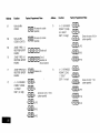
The Limitations
ofthisAlarm
System . . . . . . . . . . . . . . . . . . . . . . . . . . . .
Limited Warranty . . . . . . . . . . . . . . . . . . . . . . . . . . . . . . . . . . . . . . . . . . . .
.
.
.
.
.
.
.
.
Diagrams
Diagram l, Summary of Connections
. . . . . . . . . . .
Diagram 2, 24-Pin Connector
with Flying Leads
(4130XT Field Wiring interface)
. . . . . .
Diagram 3. Keyswitch
Wiring...
. . . . . . . . . . . . . .
Diagram 4. Installing the Digital Communication
Interface Board . . . . . . . . . . . . . . . . . . .
Diagram 5. 4152LMlnstallation
and Wiring to 4208
Diagram 6.4130XT
Connector
Interfacing
and
4171XT Wiring Connections
. . . . . . . . .
Diagram 7.1nserting
Nameplate
. . . . . . . . . . . . . . .
Diagram 8. Wall Preparation
for Flush Mounting . . .
Diagram 9. Flush Mounting
the4130XT/4137/4147
Diagram 10. Removing
Main Circuit Board for Fuse
.
.
.
.
.
Template
for Mounting
the4130XT/4137/41
.
.
.
.
.
.
.
.
.
.
.
.
.
.
.
.
.
.
.
.
.
.
.
.
.
.
.
.
.
.
.
.
.
.
.
.
.
.
.
.
.
.
.
.
.
.
.
.
.
.
.
.
.
.
.
.
.
.
.
.
.
.
.
.
.
.
.
.
.
.
.
.
.
.
.
.
.
.
.
.
.
.
.
.
.
.
.
.
.
.
.
.
.
.
.
.
.
.
.
.
.
.
.
.
.
.
.
.
.
.
.
.
.
.
.
.
.
.
.
.
.
.
.
.
.
.
.
.
.
.
.
.
.
.
.
.
.
.
.
.
.
.
.
.
.
.
.
.
.
.
.
.
.
.
.
.
.
.
.
.
.
.
.
.
.
.
.
.
.
.
.
.
.
.
.
.
.
.
.
.
.
.
.
.
.
.
.
.
.
.
.
.
.
.
.
.
.
.
.
.
.
.
.
.
.
.
.
.
.
.
.
.
.
.
.
.
.
.
.
.
.
.
.
.
.
.
.
.
.
.
.
.
.
.
.
.
.
.
.
.
.
.
.
.
.
.
.
.
.
.
.
.
.
.
.
.
.
.
.
.
.
.
.
.
.
.
.
.
.
.
.
.
.
.
.
.
.
.
.
.
.
.
.
.
.
.
.
.
.
.
.
.
.
.
.
.
.
.
.
.
.
.
.
.
.
.
.
.
.
.
.
.
. . . 75
...76
...76
...76
...77
...77
. . . 80
. . . 82
. . . . . . . . . . . . . . . . . . . . . . . . . . . . . . . . . . . . . . . . . . . . . . . . . . . . ..I7
. . . . . . . . . . . . . . . . . . . . . . . . . . . . . . . . . . . . . . . . . . . . . . . . . . . ...18
. . . . . . . . . . . . . . . . . . . . . . . . . . . . . . . . . . . . . . . . . . . . . . . . . . . . . . 19
. . . . . ,! . . . . . . . . . . . . . . . . . . . . . . . . . . . . . . . . . . . . . . . . . . . . . . . 20
. . . . . . . . . . . . . . . . . . . . . . . . . . . . . . . . . . . . . . . . . . . . . . . . . . . ...21
. . . . . . . . .
. . . . . . . . .
. . . . . . . . .
. . . . . . . .
Replacement
47 (provided
.
.
.
.
.
.
.
.
.
.
.
.
.
.
.
.
.
.
.
.
.
.
on separate
.
.
.
.
.
.
.
.
.
.
.
.
.
.
.
.
.
.
.
.
.
.
.
.
.
sheet)
.
.
.
.
.
.
.
.
.
.
.
.
.
.
.
.
.
.
.
.
.
.
.
.
.
.
.
.
.
.
.
.
.
.
.
.
.
.
.
.
.
.
.
.
.
.
.
.
.
.
.
.
.
.
.
.
.
.
.
.
.
.
.
.
.
.
.
.
.
.
.
.
.
.
.
.
.
.
.
.
.
.
.
.
.
.
.
.
.
.
.
.
.
.
.
.
.
.
.
.
.
.
.
.
.
.
.
.
.
.
.
.
.
.
.
.
.
.
.
.
.
.
.
.
.
.
.
.
.
.
.
.
.
.
.
.
.
.
.
.
.
.
.
.
.
.
.
.
.
.
.
.
.
.
.
...23
. . . 24
. . . 26
. . . 27
...72
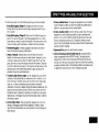
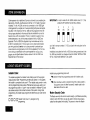
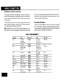
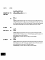
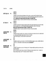
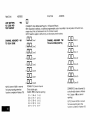
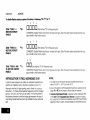
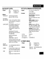
The VISTA 4130XT IS a microprocessor-based
security control which
provides up to 9 wired zones in the basic product, with expansion to an
additional
wired zones when connected toa2-wire
zone expansion bus
driven bytheoptional
No.4152LM Loop Module Thesecurity control is
housed in a wall-mounled plastlc enclosure measurmg only 8.4” (21.3
cm) wide x 4.75 (12 cm) high x 1.1” (2.8 cm) deep, and is equipped with
a multifunction 12-key digital keypad, a multipurpose LCD English language display and a built-in 85 db piezoelectric sounder that meets UL
requirements as an alarm sounder (an external sounder IS therefore
optional). ConnectIons to the security ,control are made via a 24-pm plugin connector equipped with flylng leads which interface to the wired
loops, plug-in DC Power Pack, back-up battery, optional external alarm
sounder, etc.
The security control is programmable from its own keypad or from a
4137 or 4157 remote console (optional), and can also be programmed
locally from the 699 Programmer (using a 695-30XT cartridge).
Programmed options to eslablish specific alarm and reporting features
are stored in electrically erasable, non-volatile EEPROM memory. This
means that the unit can be reprogrammed many times (unlike umts
equipped with PROMS) and that information which has been
programmed will not be lost in the event of a complete loss of power. For
installer convenience, the control is factory-programmed
to a set of
values that is designed to meet the needs of many installations. However,
these can be altered by the installer to suit the specific needs of a
particular installation or installation company, following the instructions
provided in the programming section of this manual (factory-programmed
values are also shown in this section).
A plug-in Communication Interface board (4171 XT) is required with this
system and provides communication capability (central station reporting,
etc,) over existing telephone lines as well as zone expansion
connections.
An optional, economical, remote keypad (4131 or 4147) can be used for
arming, dmarmmg, etc., from a remote indoor location within the protected premises, This unit is a compact 12-button keypad with two sysiem status indicators (LEDs) and a built-in p!ezoelectric sounder that
provides warning and alarm sounds. Requires a 10-wire connecbon to
the control.
An optional remote console (41 57) will provide system status indications
and WIIIperm[t virtually all system control functions from its keypad. The
console will also provide visible and audible indications of troubles and
alarms by means of LEDs and numeric (zone number) display and bulltIn piezoelectric sounder. Requires only a 4-wire connection to the
control
An optional remote console (41 37) is available which is identical to the
4130XT control in Its appearance, system operation, LCD displays, and
loud piezoelectric alarm sounder. Requires only a 4-wire connection to
the mam control.
A complete list of optional accessories will be found m a section toward
the end of this manual under the heading “Optional Accessories” (see
Index).
Zone Characteristics
Zone 1:
Programmable Zone, may be used as EOLR superwsed Fire
Zone (supports 2-wire Smoke Detectors), or may be used as
a non-fire zone with N C contacts only, 350-500 msec
response.
zones 2-a
Programmable
response
Programmable
response.
Zone 9
Zones, EOLR supervised, 350-500 msec
Zone, NC. contacts only, fast 10-15 msec
Back-up 12V DC Battery
DC Power Pack
Mounted externally. A spectal backbox (4132) is available for mounting
the battery in the wall behind the Control. Rechargeable 12-volt, 1.2 AH
Lead Acid.
Plug-in Power Pack (DC power converter). Plugs into unstitched
2-prong
110 volt AC outlet providing 24-hour serwce. Power Pack (1 350) supplies
unregulated 18V DC output (700 mA max) for powering the Control.
The No. 4130XT allows the installer to call it using switched network
phone lines so that the control/communicator
can be remotely
programmed and/or commanded from a No 699MD Intelligent
Programmer or an IBM compatible Personal Computer (PC). See Note 2
under Remote Capabilities in this section.
4 Central Station Advisory Note: Any condition that causes the system
to initiate a call back to a telephone number from which it can be
reprogrammed or commanded (in fact, even for a local reprogramming
of the EEPROM) causes a unique report to be sent to the central station’s alarm Ioggmg digital receiver.
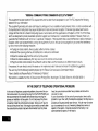
Accessing of the No. 4130XT from a remote location is protected against
compromise by someone attempting to defeat the system, using 4 levels
of security protection:
At the premises
1 Security Code Handshake: An 8 digtt Central Station ID code must
be matched between the No. 4130XT and the Central Station.
2 Hang-up and call back: Calling the
allow programming, as a successful
No. 4130XT breaking the phone line
the (internally stored) central station
No. 4130XT does not directly
handshake merely results in the
connection and then calling back
service phone number’.
3 Data Encrwtion: Data passed between the central station and the
No, 4130X~”is encrypted for security so that it is very difficult for a foreign device tapped into the phone line to take over communication
and substitute system compromising Information.
*NOTE:
In situations where a service person is on stte and the system is
installed inside a PABX, it is possible to initiate a download from
the protected premises by keying [installer or master security
code] + [#] + [1].
Equipment Required
The No. 4130XT must be used with its No. 4171 XT Communication
face board if remote programming and/or control is desired.
Inter-
At the central station (or the installer’s office/home):
A No. 699MD Intelligent Programmer that incorporates an internal
modem and a No. 695-30XT Program Cartridge.
OR
c An IBM PC compatible computer, a Modem (check with Ademco Factory
Technical Support for the specific brand and model to be used), No.4130PC
Downloading Software Diskette, and appropriate interconnecting cables.
●
Remote Capabilities
(See Note 2)
Programming:
All programming functions accessible from the unit’s keypad or via local
No 693 direct programming.
Commanding:
There are two types ot commands
1. Control Commands
—
-
To Arm the System in the Away Mode* (’)
To Disarm the System* (t)
To Bypass a Zone
To Force the System to Accept a New Program Download
To Shut DowrI Communication (dialer) Functions (non-payment of
monitormg fees m an owner’s system)
- To Shut Down all Security System Functions (non-payment for a
leased system)
- To Inhibit Local Keypad Programming (prevents takeover of your
accounts)
2. Status Commands —
- To Cause the System to Upload a Copy of its Resident Program to
the central station
To Read System Status:
Arming Status
Ready Status and Current Faults
Presence of Alarms (pastor present)
Presence of Troubles (past or present)
AC Power Status
Bypass Status and Current Bypasses
*NOTES
manded to hang up See the 4130PC or 695-30XT instructions for details.
that can be issued to the system:
1.If the system is programmed for open/close
reporting by
user, User #7 will be reported.
2. After the4130XT and the 699 or PC have established valid
communication, each 4157 console displays an ‘OC’ signifying that It IS busy (occupied). Also, the 4130XT is not
responding to faults in its zones. The 4130XT will resume
the normal security tunctlons (mcludmg responding to faults
that look place during the downloading) after it is com-
The detailed operation of the functions described below IS covered m the
Installation Instructions for the No. 695-30XT Program Cartridge and for
the 4130PC Download Software Diskette.
-
To
To
To
To
To
To
Read
Read
Read
Read
Read
Read
List of Faulted Sensors
List of Bypassed Sensors
10 Day Alarm History Log
10 Day Trouble History Log
List of Sensors Currently m Alarm
List of Sensors Currently in Trouble
Remote Communication Specifications:
. Program Download Time — 1 minute for a complete program
. Typical Total Time Including Call Up/Call-Back
Remote Command/Programming
●
●
— 3-4 minutes
Advisory Notes:
Alarm and Trouble Reporiing are disabled during the time that the SYStem and the central station are linked to each other for the described
functions, following a valid exchange of codes.
Keypad entries are ignored during the same time interval cited above.
. Should an alarm transpire during the remote program/control
interval,
the system would not respond to the alarm condition untd the remote
mode was ended. The local zones and the Nos. 4190WH, 4192,
4194WH, 4196, and 4208 all store their fault conditions until they are
read by the Control, As such, alarm conditions from the local and
expansion zones would not be missed, only delayed.
. A copy of the program downloaded may be produced from either the
No, 699 Intelligent Programmer or the IBM PC compatible computer,
using those products’ internal report generators, when an optional printer is connected.
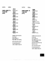
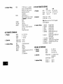
For each zone used, one of the following zone types must be selected:
1. Entry/Exit Burglary (Delay #1). Assigned to sensors on doors
through which entry and exit WIII normally take place when the system E armed.
2. Entry/Exit Burglary (Delay #2). May be set for different delay than
above. For use with sensors on overhead garage doors, etc., where
longer delay w needed to reach the keypad in the main portion of the
house or building, and more delay is needed to exit the premises.
3. Perimeter Burglary. Normally assigned to all sensors on exterior
doors and windows requiring mslant alarm.
4 lntetior, Follower. Delay edalarm only ifthe Entry /Exit zone is
faulted first otherwise, produces an instant alarm. Assigned to zone
covering an area such as a foyer or lobby through which one must
pass upon entry toreach thekeypad todisarm the system Designed
to provide instant intrusion alarm in the event an intruder hides on the
premrses prior to the system being armed or gatns access to the
premises through an unprotected area.
5. Trouble by Day/Alarm by night. Can be assigned to a zone which
contains a foil-protected door or window (such as in a store), or to a
zone covering a “sensitwe” area such as a stock room, drug supply
room, etc., or other controlled access area where immediate
notification of an entry M desired. During the disarmed state (day), the
system will prowde latched Control/Console
annunciation (and central station report, if desired) of openings or troubles (such as sensor
malfunctions or foil breaks), During the armed state (night), violations
will initiate an alarm.
6. 24-hour Silent Alarm. This type generally assigned to a zone containing an Emergency button that is designed to initiate an alarm
report to the Central Station, but which produces no local displays or
alarm sounds.
7 24-hour Audible Alarm. This type also assigned to a zone containing an Emergency button, but which will initiate an audible alarm in
addition to an alarm report to the Central Station.
B 24-hour Auxiliary Alarm (Control internal sounder only). This type
assigned to a zone containing a button for use in personal emergencies, or to a zone containing monitoring devices such as water
sensors, temperature sensors, etc Designed to initiate an alarm
report to the Central Station and also provide Control/Console
alarm
sounds and alarm displays.
9 Supervised Fire (alarm on short/trouble
on open).
10 Interior that always has Entry/Exit Delay #1 (except that Entry
delay is suppressed in the INSTANT mode). This type Iypicaliy
assigned to an interior zone containing a PIR that covers an area
through which the user must pass to reach the Control for disarming
purposes (whether inside or first entering). Ideal for an area such as
an apartment entrance foyer in which a keypad is located.
The following is a description of the various zone types available which
must be selected for each physical zone. You may w!sh to use Table A at
the end of this description to record your selections.
Type
1. BURGLARY ENTRY/EXIT
(DELAY #l): This zone type is not
enabled after armmg untd termination of the (EEPROM defined)
Exit delay #l Upon entry, the Control WIII simply emit three
short beeps as a warning th~l the system must be dtsarmed
(for added security, this system does not emit wammg s{gnals
throughout the Entry delay period). If Code + OFF is not entered
before term} nation of the (EEPROM defined) Entry delay #1, an
alarm will be imtlaled at the buill-in sounder, if program
enabled, and an external alarm and latched LCD dmplay. If a
Commurucatlon board is used, a system-wide EEPROM
defined number of alarm reports for this zone will be allowed to be
transmitted (swinger suppression) In one armed period.
Restorals will be sent when the zone is restored for a time
greater than its physical response hme (less than 1 second).
Communication board is used, a system-wide EEPROM
defined number of alarm reports for this zone WN be allowed to
be transmitted (swinger suppression) in one armed interval.
Restorals wtll be sent when the zone ts restored for a ttme
greater than its physical response time (less than 1 second),
During the disarmed state, a faulted zone will result in a NOT
READY display Subsequent depression of the READY key WN
cause all the faulted zones to be sequentially displayed No
communicator reports WIII be initiated.
Type
Dur(ng the disarmed state, a faulted zone wdl result !n a NOT
READY display. Subsequent depression of the READY key wdl
cause all the faulted zones to be sequentially displayed. No
communicator reports will be imbaled.
..
TVDt2
2. BURGLARY ENTRY/EXIT
(DELAY #2k This zone tvDe is not
enabled after armmg until ter’minabon of \he (EEPROM’defined)
Exit delay #2 Upon entry, the Control will simply emit three
short beeps as a warning that the system must be disarmed
(for added security, this system does not emit warning signals
throughout the Entry delay period) If Code + OFF is not entered
before termination of the (EEPROM defined) Entry delay #2, an
alarm will be imtiated at the budt-rn sounder, if program
enabled, and an external alarm and latched LCD display. If a
3, BURGLARY PERIMETER: While the System is armed, a
faulted zone w(II initiate an alarm at the built-in sounder, if
program enabled, and an external alarm, a latched LCD
dmplay, and a (EEPROM selected) communicator report.
Depression of any key will silence the Control’s local alarm
sounder for 10 seconds. A system-wide EEPROM defmed
number of alarm reports for this zone will be allowed to be
transmitted (swinger suppression] by the commumcator m one
armed period. The communicator will transmit a restoral message when the zone m restored for a time greater than ils physical response time (less than 1 second).
During the disarmed slate, a faulted zone will result in a NOT
READY display, Subsequent depression of the READY key will
cause all the faulted zones to be sequentially displayed. No
commurlicator reports will be initiated.
Type
4. BURGLARY INTERIOR, FOLLOWER: This zone will always
have Exit Delay #l The zone has an Entry Delay if preceded
by a fault in an Entry/Exit zone (type #1 or #2) If not preceded
by an Entry/Exit zone fault, an Immediate audible local (Control) and external alarm, latched display, and a (EEPROM
selected) commumcator report are mltlated. Depressing any
key at the Control will silence the Control sounder for 10
rseconds A system-wide EEPROM defined number of alarm
reports for this zone will be allowed to retransmitted (swinger suppression) by the communicator in one armed period, The
communicator will transmit a restoral message when the zone
is restored for a time greater than its physical response time
(less than 1 second).
Type
A system-wide EEPROM defined number of alarm reports for
this zone will be allowed to be transmitted (swinger suppression) by the communicator
until an OFF sequence is performed. The communicator will transmit a restoral message
when the zone is restored for a time greater than its physical
response time (less than 1 second).
During the disarmed state, a faulted zone will result in a NOT
READY dwplay. Subsequent depression of the READY key will
cause all the faylted zones to be sequentially displayed, No
communicator reporls will be initiated,
Type
5. BURGLARY PERIMETER, TROUBLE BY DAY/ALARM BY
NIGHT: During the disarmed state (day), faulting the zone will
initiate a “trouble” display and a latched sounder (beeping).
The Control will beep rapidly along with a latched display of the
faulted zone and the word CHECK, Pressing any key will
silence the beeping for 10 seconds. Code + OFF will silence
the beeping but will only clear the display of a zone that had
the fault condition removed.
During
sensor
armed
should
faulted
the disarmed state, NOT READY will be displayed if a
is faulted. The burglary portion of the system cannot be
if this zone is faulted. An OFF sequence (code plus OFF)
be performed prior to arming the system or viewing the
zones via the *key,
Type
7. 24-HOUR AUDIBLE ZONE: Faulting a zone of this type will
initiate a loud audible alarm externally and at the Control, an
LCD display, and a (EEPROM selected) communicator report.
Pressing any key will silence the Control sounder for 10
seconds. Keying Code plus OFF will permanently silence the
alarm. A system-wide EEPROM defined number of alarm
reports for this zone will be allowed to be transmitted (swinger
suppression) by the communicator until an OFF sequence is
performed The communicator will transmit a restoral message
when the zone is restored for a time greater than its physical
response time (less than 1 second).
Type
8. 24-HOUR AUXILIARY ZONE Faulting a zone of this type will
initiate a steady alarm sound at the Control, an
ALARM display, and a (EEPROM selected) communicator
report. Pressing any key will silence the Control sounder for 10
seconds. Keying Code plus OFF will permanently silence the
If a Communication board is used, each trouble will result in a
“trouble” report (if programmed). A trouble restoral message
will be sent as each zone is restored to normal condition. The
maximum number of trouble reports per armed period will be
limited by the system-wide EEPROM number of alarm reports
option (swinger suppression).
During the armed state (night), the local (Control) and external
(if used) alarm sounder will activate and the communicator will
report alarms. A system-wide EEPROM defined number of
alarm reports for this zone will be allowed to be transmitted in
one armed period, Restorals will be sent when the zone is restored for a time greater than its physical response time (less
than 1 second).
6. 24-HOUR SILENT ZONE Sensors assigned to this zone,
when faulted, will initiate a communicator report. There will be
no local displays or alarm sounds. Upon keying Code plus OFF,
there will be a memory indication of the faulted zone.
alarm. A system-wide EEPROM dehned number of alarm
reports for this zone will be allowed 10 be transmitted (swinger
suppression) by the communicator untd an OFF sequence is
performed. The communicator will transmit a restoral message
when the zone is restored for a time greater than its physical
response time (less than 1 second).
Type
9. FIRE ZONE: Opens in this zone will result in “troubles”. Shorts
will result in alarms. Note: Zone 1 will support 2-wire Smoke
Detectors (using the EOL resistor configuration): Zones 2
through 8 can be used for heat detectors and pull stations and
for 4-wire Smoke Detectors with external (manual) power interrupt; Zone 9 cannot be used for Fire.
Fire zones may not be bypassed. A fire zone m trouble will not
prevent the burglary system from being armed in any mode
A system-wide EEPROM defined number of alarm reports for
this zone will be allowed to be transmitted (swinger suppression) by the communicator in one armed period. The communicator will transmit a restoral message when the zone
is restored (less than 1 second).
Type 10. INTERIOR DELAY ZONE: This type of zone will always have
an Entry delay #l and Exit delay HI. Thw zone IS not enabled
after armmg until termination of the (EEPROM defined) Exit
delay #1. If this zone E faulted, three beeps will be emitted by
the Control. If Code + OFF E not entered before termination of
the (EEPROM defined) Entry delay #1, an alarm will be mitlated.
A system-wide EEPROM defined number of alarm reports for
this zone WIII be allowed 10 be transmitted (swinger suppression) by the communicator in one armed period. The communicator will transmit a restoral message when the zone IS restored for a time greater than its physical response time (less
than 1 second).
During the disarmed state, a faulted contact WIII result m NOT
READY being displayed. Subsequent depression of the READY
key will cause all the faulted zones to be sequentially displayed,
but no commurucator reports will be initiated.
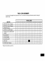
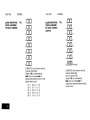
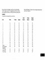
TABLE A. ZONE ASSIGNMENTS
A zone type must be assigned to each physical zone m use For convenience,
selechons made
ZONE TYPE
1
1 ENTRY/EXIT,
Delay #1 (Burglary}
2. ENTRY/EXIT,
Delay #2 (Burglary)
2
3
415
67
the following chart has been provided for checking off
PHYSICAL ZONES
8
9
10
11
3. PERIMETER (Burglary)
4. INTERIOR, FOLLOWER (Burglary)
5. TROUBLE BY DAYIALARM
(Burglary)
BY NIGHT
6. 24-HOUR SILENT
7. 24-HOUR AUDIBLE
8. 24-HOUR AUXILIARY
9. FIRE ZONE”
10 INTERIOR. DELAY (Buralarv)
‘Physical
Zone 9 cannot be used for Fire
I
I
I
12
13
14
15
16
17
Zone expansion to an additional 8 zones is achieved by first Installing the
optional No. 41 52LM Loop Module onto the No. 4171 XT (after [t has been
installed). The No. 4152LM can then be connected to a No. 4208 Eight
Zone &pander by a single pair of w!res providing both power and signaling. Path of the 8 zones on the No. 4208 can be programmed from the
various types described in this manual that are available for use on the
basic.9 zones, wdh one exception. There IS no ability to support 2 wire
smoke detectors on any of the zones available in the No. 4208 Zone
Expander The No. 4208 Zone Expander may be located near the No.
4130XT or remotely from )t. The two wire run to it should utihze twisted
pair wiring and should not be run in,close proximity to profected premises intercom wiring [at least a 3-inch (8 cm) separation]. For the maximum wiring run permissible to the zone expander for various wiring
gauges, see the Specifications Section relatwe to the No. 4208 Zone
Expander later in this manual.
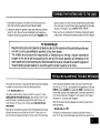
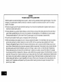
IMPORTANT
Installer Code:
Installer exits programming mode with:
The installer programs the Installer Code initially as part of the programming procedure (see “Programming the Security Control”) In this system,
the installer is considered to be user #1 The installer code permits re-entry
into the programming mode (unless *98 has been previously used to exit
the programming mode or if user #1 was not enabled in Address *52) and
also allows access to the normal functions of the system. During initial
programming, the installer also programs the Master security code into the
system
❑ ❑ ❑ ❑
Installer Code (User #l ), assigned during
programming.
In order to utilize the No 4208 to obtain zones 10-17, that
product’s DIP switches must be set as follows:
2
ON
3
ON
4
ON
5
OFF
noun
(as If set for sensor numbers 113-120, as cited in the instructions for the
No 4208)
Installation instructions for the No 4152LM and wiring connections to the
No, 4208 are provided m a subsequent secllon entitled “INSTALLATION
OF No. 4152LM AND WIRING TO No. 4208”.
*99 (allows re-entry into programming mode with installer code).
or
X98 (does not allow re-entry to programming mode unless system is
first powered down and then repowered). Installer code IS disabled whemthis exlf is used
Master Security Code
The Master security code can be used to assign up to thirteen secondary
codes (to users #3-#1 5); it can also be used to remove all secondary
codes from the system (individually). The person to whom the Master
code IS assigned IS considered to be user #2. In some apphcations
(commercial installations for example), user #2 (with Master code) WN
be the main user of the system (see Application 1 on a following page)
In other applications [such as m an apartment complex, for example),
user f12 (with Master code) may not be the aclual end user of the system
(see Application 2 on a following page).
Secondary security codes are assigned by user lf2 [with Master Code)
as follows
Master Code + CODE key + User # (03-15) + Secondary Code
The system wdl emd a single beep when each secondary code has been
successfully entered.
Note: When a secondary code is inadvertently repeated for different
users, or one user’s code is another’s duress code, the lower user
wdl take priority.
Indtwdual secondary security codes can be deleted by user M2 (with
Master Code) as follows.
Master Code + CODE key + User # (03-15) + Master Code
Note: All security codes, Master and secondary, permit access to the
system for arming, disarming, etc.
Secondary (Temporary)
Security Codes:
As stated prewously, up to thwteen secondary codes can be assigned —
to users 3 through 15. The configuration in Application 1 shows that
secondary (or temporary) codes may be assigned by the primary user
(user #2) to as many as thirteen employees, each with a unique code
Note that user #3 can also assign secondary codes to users 4-14 if
required, but in the typical arrangement shown in Application 1, there
may never be a practical need for this. If so, the primary user (#2) can
elect to omit user #3 when assigning secondary codes
In the configuration
shown in Application
2, user #3, who is the primary
user, may need to assign secondary (temporary) codes to maids, cleaning persons, etc. Since the system allows user #3 to assign secondary or
temporary codes to as many as eleven users (4-1 4), this need can be
met User #3 cannot assign (or delete) user #1 5’s code, which ISstrictly
under the control of user #2, who may be the building manager or owner
m the configuration shown in Application 2, See Table B, which illustrates
the various levels of authority that exist for security codes,
User H3 can assign secondary (temporary) codes for users, 4-14 as
follows’
User #3 Code + CODE key + User # (04-14) + Secondary Code
User #3 can delete secondary codes assigned to users 4-14 as follows:
User #3 code + CODE key+ User # (04-14) + User #3 Code
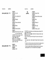
TABLE B. LEVELS OF AUTHORITY
CODES
User
No.
Can assign or delete
Sacondary Code of User:
#1 (Installer)
#2
#3
#4- Ff15
NONE
#3 through #15
#4 through #14
NONE
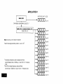
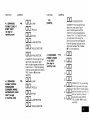
FOR SECURITY
APPLICATION 1
,
MASTER SECURITY CODE
MAIN USER
I
CAN ASSIGN TEMPORARY CODES TO: I
“Clnclcl”,er,,
i
Note: All codes can Arm/Disarm
the System
User #6
*User #3 can assign secondary codes to
users 4-142
User //7
User #8
User #9
User #1 O
1 A secondary
(temporary)
code is assigned as follows.
User #2 (Master) Code + CODE key + User # (03-15) + Temporary
Code
2 User #3 can assign temporary codes as follows:
User #3 Code + CODE key+ User # (04-1 4) + Temporary Code
User #11
User #l 2
User #13
User #l 4
User #15
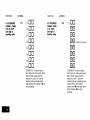
APPLICATION 2
BUILDING
MANAGER,
(User #2)
MASTER SECURITY CODE
ETC.
-0000
CAN ASSIGN SECOfiDARY
1
r
SECONDARY
SECURITY CODE
❑
000
BUILDING
~
EMPLOYEE,
(User #15)
User #15
1
APARTMENT OWNER,
(User #3)
ETC.
SECURITY CODE’
ETC.
User #3
“0000
CAN ASSIGN
TEMPOiARY
TEMPORARY
SECURITY CODES
CODES TO 2
t,
MAID, CLEANING PERSON,
(User #4 #14)
c
ETC.
*
1
<
Note: All codes can Arm/Disarm
user,,
CODES TO 1
the System
<
‘This code, although actually a secondary code, will serve as a master
security code for the apartment owner, etc. since user #3 is the primary
user of the system in this application.
--c
i A secondary code is assigned as follows:
+000
--c
Master Code + CODE key + User # (03-15) + Secondary Code
2 A temporary code is assigned as follows:
User #3 Code + CODE key + User # (04-1 4) + Temporary Code
@
❑ on
❑
❑
❑
❑
❑
User #4”
00
User #5
00
User #6
00
User #7
on
User #8
00
User #9
❑ un
❑ on
❑m
❑ clcl
User #10
User //1 1
User #12
User #13
User #14
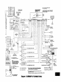
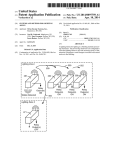
(See Diagram 1, Summary of Connections)
A 24-pin plug-in connector with flying leads is provided to interface the
4130XT to the wired loops, the external alarm sounder, the back-up battery, to externally powered devices (auxiliary current), and to the plug-in
DC Power Pack,
of wires used In these harnesses is identical to that used w’ the 24-pm
connector with 18-inch leads. Refer to “Optional Accessories” for part
numbers of available wiring harnesses
Grounding
The 24 flying leads, each 18 inches [46 cm) m length, are umquely color
coded, as shown in Diagram 1 and also in Table C which indicates the
color, usage and pin connection for each lead
the System
A proper earth ground must be provided for the system. The While lead
(pin 11) on the 24-pin connector is the earth ground lead (see Table C).
Connect this lead to a suitable earth ground (a metalhc cold water pipe
or electrical box may be used in some locations).
Note: Optional 30-ft (9 m) and 15-ft (46 m) wiring harnesses with a 24pln connector at one end are ava;lable for interface wiring. Color coding
TABLE C. WIRE ASSIGNMENTS
Connector
Pins
Usage
Wke
Dc(+) INPUT
(from plug-n
OC Power Pack)
Red/Green
Color
Wire Color
Usage
Blue
DC (-) INPUT
(from plug-in
OC PQwer Pack)
(12)
(24)
Whtte
EARTH
(11)
(23)
BATTERY(+)
Red
Black
BATTERY (-) and
REMOTE CONSOLE
GROUND
(lo)
(22)
AUX/REMOTE
CONSOLE/EXT
ALARM SOUNDER
PWR (+)
Red/Black
Violet
AUX PWR (-)
(9)
(21)
ExT ALARM
SOUNDER(-)
Brown
GND
Gray
ZONE RETURN
(8)
(20)
ZONE
4(+)
Wh(te/Yellow
Tan
ZONE
RETURN
(7)
(19)
ZONE
5(+)
White/Green
ZONE
2(+)
(s)
(18)
ZONE
6(+)
Whtte/Blue
(5)
(17)
ZONE
9(+)
While /Black
(4)
(16)
ZONE
7[+)
Wh!lelvmlel
(3)
(15)
ZONE
8(+)
Whfte /Gray
(2)
(14)
ZONE
EOLR
l(+)
LOOP
RediYel[ow
(1)
(13)
DATA oUT
(Remote Console)
Whltel
Red
Wh!te/Orange
ZONE 3(+)
Whte/
ZONE
1 RETURN
Orange
Brown
ZONE
t(+)-N
Pink
ZONE
RETURN
Green
DATA IN
(Remote Gonsote)
C
LOOP
Yellow
.,”.
,...
,“ ,..,.
. .
,X4,
hii?
+—
.,,,
..,”
LJ
. . ,,0.
UN ,.!7
. . ...7
,“”,
%
“
. .
. . . .
,,. ”.,
!”..,,
I +%’” !=%.==kn.-
g
.
ii!
I
--------------
OPTlONAL
4140
RELAY
------------ MOOULE
I
3AMP
FUSE
($LO-BLO) [(0
‘
u, W*
*ONS:=Y
+--~
II ,o-.a’”’”’!!?,~
‘
‘—---Rm’”’””j
s,.,.
-“.,
,0..
TOZONE
RETuRN
,P!N
27W8)
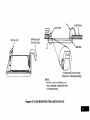
Diagram 1. SUMMARY
OF CONNECTIONS
,*
w
7,.702
milov.mm
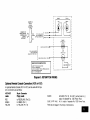
Remote Keyswitch Operation
TAB
& Wiring
ISEE
NOTE
BELOW
An optional Remote Keyswitch may be used for remote arming and disarming (this is an installer-programmed
option). A normally-open momentary switch is connected across Zone 7 (which must be given up as a
protection zone). A momentary short of the zone will arm the System in
the AWAY mode; it the key is held (short maintained) for over 3 seconds,
the System WIII arm In the STAY mode. When a momentary short E applied subsequently, the System will disarm. A keyswitch tamper
(normally-closed)
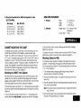
switch wired in series with zone 7 will disable keyswitch operation until the system is next disarmed via a keypad, if activated. Refer to Diagram 3 for Keyswitch wiring details
RECORDING
INSTALLATION
DATA
When all interface
wlrlng is completed,
record w)nng usage
In the spaces provided on the Wire
Assignment tag attached to the wires
on the 24-pin connector. This will
provide a permanent record of the
lnlerface wiring
connections for
future serwcing,
NOTE: Regardless whether End-of-Line superwslon IS selected or not (In
Address *4 I ), an end-of-line resistor must still be used for proper
functioning of the keyswltch.
Optional Remote Keypad Connection
(4131/4147)
An optional remote keypad (4131 /4147) may be used with the System.
Two 10-pin female connectors have been supplied for keypad interfacing
to the 4130XT Control (see Diagram 1, Summary of Connections) The
two connectors, which are identical, are equipped with color-coded flying
leads that are 12 inches (30 cm) in length.
One of these connectors is attached directly to the mating 10-pin male
connector on the 4131 /4147 remote kevDad (the connector can only be
inserted one way, and will lock in place):”
The other connector is connected to the 4130XT Control wa a “straight”
male-lo-male 10-~in ada~ter (suPrJlied).
Specific information regarding the use of the adapter and connection to
the 4130XT Control is provided in the section entitled MOUNTING THE
4130XT.
-
SEE
WIRING ASSIGNMt NT
TABLE IN TEXT
NOTE
TOREMOVE
CONNECTOR
FROM
CONTROL
BOARD
AFTER
INSERTION.
S0UEE2&
TABANDPULL
OUTWARD ASIDEToSIDEROCKING
M0710N
WITH
Diagram 2.
24-PIN CONNECTOR
WITH FLYING LEADS
(4130XT WIRING INTERFACE)
. ---r
(SA4131-1O)
REMOTE
KEYPAD
CONNECTOR
CONNECTS
TO
REMOTE
KEYPAD
INTERFACE
ON
CONTROL
{SEEDIAG1) Q
----
IARMED1
RED
----—
(READY)
GREEN
1
l-?=
RED(PIN
To,LY\NGLEADS
ON 10. PIN REMOTE BLUE
KEYP4D
CONNECTOU
~R&EN
E
8L!JE
GREEN
[
REO
bl-
3,—
I
1
I
WHITEIVIO LET (PIN 16) 4
r
TAMPER
SWITCH
(NCI
I
I
I
I
C“’’’&e”-’
No4073.70H)(W SECURITVKEYLWK,SPWN13LOADEO(N 0 )
Diagram 3. KEYSWITCH
Optional Remote Console Connection
An optional Remote Console (4137or4157)
tem. Connections are as follows:
WIRING
(4137 or 4157)
can be used with the Sys-
413714157
Leads
24-pin Connector
Flying Leads
BLACK
RED
GREEN
YELLOW
to RED/BLACK
(Pin 22)
to GREEN (Pin 1)
to YELLOW (Pin 13)
Refer also to Diagram 1, Summary of Connections.
BLUE (41 37 only)
to BLACK (Pin 10) For 4137, connect also to (-)
output of separate No. 1350 Power Pack.
to (+) output of separate No. 1350 Power Pack.
m
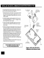
The optional Digital Communlcatlon Interface Board IS attached to the
rear of the Control as follows (refer also to Diagram 4).
DIG1T4L
COMMUNICATION
INTERFACE
BOARD
\
13P1N INTERFACE
CONNECTOR (ADAPTER
/PINS INSERTED FROM
1 Remove the back cover on the Control. The securing screw at the left
front of the Control must be removed to release the back cover (see
Diagram 6 for screw location). Discard the back cover, but retain the
screw for use later.
2 Insert three small plastic standoffs (supplied) into the three holes on
the Control board identified as “A”, “B” and “C” in Diagram 4 Press
them in firmly until they “snap” into place.
3 Insert the 13-pin male-to-male adapter (supplled) into fhe interface
socket pin holes on the underside of the Commumcation Interface
board, as shown.
4 Attach the Communication Interface Board to the Control board as follows. Guide the adapter pins (on the Communication board) into the
interface pin holes on the Control board, simultaneously allowing the
pointed ends of the standoffs to partially enter the holes in the Communication board (shown as “A”, “ B“ and “C” in the Diagram), Before
proceeding, make sure the adapter pins are properly entering the pin
holes on the Control board. Then press the Communication board
down until the connector pins are fully seated and the standoffs
“snap” into place in the Communication board, thus holding the board
securely to the Control.
This completes the installation of the Communication
Wiring connections are not made at this time.
STANDOFFS
,3)
IN 3 PLACES
(HOL
B AND
u
D FIRST)
C)
Interface board,
t
[
RD
DO NOT CONNECT THE OUTPUT OF THE 4171XT
TO A FIRE OR POLICE HEADQUARTERS
Diagram
4. INSTALLING
THE DIGITAL
COMMUNICATION
INTERFACE BOARD
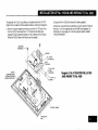
The optional No. 4152LM Loop Module is installed onto the No4171XT
Digital Communications Interface board as follows, referring to Diagram 5.
a Note the 8 square-shaped connector pins on the 4171 XT board. PosItlon the 4152LM board” over the 4171 XT board so that these pins
engage the mating sockets (header) on the underside of the 4152LM.
Press the 4152LM down until the pins are fully seated.
b. Secure the No. 4152LM by means of 3 srews (supplied).
Connect two wires from the looD terminals (1 and 2) on the 4152LM to
termnals 11 and 12 (respectively) on the “4208 Zone Expander. For
information on wire usag”e, etc., ~efer to a prewous section entitled
“ZONE EXPANSION”.
Diagram 5. No. 4152LM INSTALLATION
AND WIRING TO No. 4208
‘=Q&y
w
CONNECTOR
PINS
‘CONTROL
130AR0
There are three methods that may be used for mounting the 4130XT
Control, as follows:
1, Surface Mounting: This type of mounting IS possible only when a battery backbox is not required (battery back-up power will be supplied
from a remote location) and when the digital communication interface
board is mounted to the unit using the No. 4143 Extender Ring to
increase the depth of the unit.
2. Flush Mounting. This type of mounting is used when the battery
backbox is required for support of the back-up battery In the wall
behind the 4130XT, or when the No. 4143 Extender is not attached to
the rear of the 4130XT Control. This mounting method is also applicable if a “rough-in” ring (41 33) has been installed in the wall in a new
construction application.
3. Cabinet Mounting: In buildings using concrete, cinder block or brick
wall constructions, the surface or flush mounting method above may not
be practical, and a third method using a wall-mounting metal cabinet
can be used (see “Optional Accessories”). The 4130XT Control is
mounted in a cut-out specially provided for this purpose in the door of
the cabinet, and the back-up battery (if used) is installed within the
cabinet. Also available for use within the cabinet are connector blocks
which can be used to connect the 4130XT flying leads to the field wiring.
Instructions for this type of mounting are provided in Appendix A toward
the end of this manual.
Proper selection of mounting location and height is important for optimum
viewability of the LCD display on the control (or remote console). A location in which lighting is directly above the control should be avoided,
since this can shadow the display. For optimum viewing, the control
should also be mounted so that the display is below eye level to ensure
that the system’s user will look down at the display.
Surface Mounting:
Notes:
1. This method of mounting is not applicable for UL installations.
2. This method of mounting cannot be used if a 4t52LM Loop
Module is used.
Use the template provided (on a separate sheet) to mark the positions on
the wall for the screw mounting holes and the cut-out for the interface
wlrlng. Use wall anchors for the screws and make the cut-out in the wall
no larger than indicated,
Pull the interface wiring in the wall through the cut-out. Splice these wires
to the 24-pin interface connector wires as indicated in Diagram 1 and in
Table C previously. Insulated soiderless wire sphces (such as Ademco
No, 311 ) may be used for splicing. Check wire connections carefully
before splicing.
Note
If the optional 15-ft (4,6 m) or 30-ft (9 m) wiring harness has been
used for interface wiring, splices will not be necessary behind the
control since these harnesses are terminated with a 24-pin connector which can be connected directly to the 4130XT
If the 4131 /4147 Remote Keypad is being used, splice those wires to the
wires on the 10-pin connector supplied for this purpose, being sure 10
match wire colors. Be sure to insulate all splices.
Remove the Control’s back cover. The securing screw at the front of the
Control must be removed to release the back cover (see Diagram 7 for
screw location) Pass the interface connector(s) through the opening in
the back cover and then mount the back cover to the wall surface with
screws,
Install the No. 4143 Extender Ring onto the back cover (see the instructions accompanying the No. 4143).
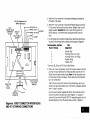
Attach the interface connector(s) to the board at the rear of the Control
as follows, referring to Diagram 6:
a. Aliachthe 24-pin connector tothemating
the bottom of the board.
DIGITAL COMMUNICATION
BOARD I INSTALLED)
GROUND
lBPIN
REMOTE KEYPAD
CONNECTOR
(IF USEOI
START
PHONE LINE (TIP)
—
1
INCOMING
STRAIGHT
10 PIN
MA LE.T6MALE
ADAPTER
—PHONE
LINE IRING)
(RING)
~1
L
HANOSET
(TIP)
12345
e
no
@
~
+:
:
REAR OF CONTRC L
(BACK COVER
REMOVED)
‘~fi~~~”
1
2
3
4
5
‘Connect
o
~,
b. Attach the 10-pin connector (if used) to the Remote Keypad connector
(1 O-pin socket) at the top of the board via the “Straight” male-to-male
adapter supplied important
Eesureto orient the connector with
BLACK lead (pin 1) to the left (when viewing the4130XT from the
rear).
Communication
Interface
Board Terminal
. .
@
pins located at
c. On the Digital Communication interface board, attach the interconnecting wires to the terminal block as follows, referring also to Diagram 6:
—
II
interlacing
ti~
Wire
Assignment
Ground Start ‘
Incoming Phone Lme (Tip)
Incoming Phone Line (Ring)
Handset (Ring)
Handset (Tip)
to BLUE lead on 675 Ground Start Module.
d. With a pair of wire-cutting pliers, snip off the 8 square-shaped connector
pins that normally interface to the4152LM and then install the4171 XT
Digital Communication Interface board. Note On later production units,
this procedure will not be necessary, Those units will be accompanied
by a note to that effect.
Attach the main body of the Control tD the Extender Ring, which is attached to the wall-mounted back cover. The Control is properly attached
when it “snaps” into place.
Use the securing screw (supplied with the No. 4143 Extender Ring) to
secure the Control to the back cover (see Diagram 7 for location of
screw hole), then insert the small VISTA XT nameplate supplied into the
recessed opening to cover the screw head, as shown In Diagram 7.
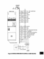
Diagram 6. 4130XT CONNECTOR
INTERFACING
AND 4171XT WIRING CONNECTIONS
INSERT
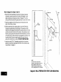
Flush Wall Mounting:
NAMEPLATE
INTO RECESSED
AREA (COVERS SCREW)
If a “rough-in” ring (41 33) has been previously installed in the wall (during new construction), disregard step 1 and proceed tostep2 since the
required opemng for the Control IS already present, If a wall plate (41 36)
is installed over therough-in ring, remove theplate to expose the
opening,
//
“1
I
L~
(@b
/
OARMED
OPOWER
\
SECURING
SCREW
Diagram 7. INSERTING
NAMEPLATE
Note: A special “trim ring” has been supplied for installation between the
wall and the Control for those cases where the opening has
inadvertently been made too large (over-cutting). The Control
fits into the recess in the trim ring which will extend M“ (1.3 cm)
beyond the Control front panel, and thus cover any opening that
might otherwise bevisible asa result of over-cutting,
2. Remove the back cover onthe Control. Thesecuring screw atthe
front of the Control must be removed to release the back cover (see
Diagram 7for screw location) Discard the back cover, but retain the
screw.
Note
/
~—
1. Cut an opening measuring 4-5/16” (11 cm) high by 7-3L” (20 cm) wide
between studs in the wall. Theopemngmust
be no less than 1-Yz” (4 cm)
from either stud. Avoid cutting the opening any larger than that specified, See Diagram 8.
Make sure that the digital communication Interface board is
mounted to the 4130XT (and the No. 4152LM Loop Module, if
applicable), as indicated previously.
3. install the Battery Backbox (4132). (Disregard this step if battery backuppower issupplied from a remote location.) If battery back-up power
is not supplied froma remote Location, the backbox supplied must be
installed behind the wall opening to support the back-up battery that
must be used. Install as shown in Diagram 8, with “lip’’ofthebackbox
hooked over the bottom edge of the wall opening.
insert the battery into the box, and make connections to its terminals
as follows, using the two 12-inch (30 cm) Red and Blackheads
(equipped with FAST-ON connectors at one end) that have been supplied. See Diagram 1.
a. Splice the wire end of the RED 12-inch lead to the Red lead (pin 23)
coming from the 24-pin connector (an insulated solderless wire
splice such as Ademco No. 311 may beused). Connect the other
end (FAST-ON connector) of the12-inch REDlead to the positive
(+) terminal on the battery.
b. Splice the wire end of the BLACK 12-inch lead to the Black lead
(pin 10) coming from the 24-pin connector (be sure to use an insulated wire splice). Connect the other end (FAST-ON connector) of
the 12-inch BLACK lead to the negative (-) termmal on the battery
Note
For ULListed usage, utilize the 4132-l (optional) battery box
cover. Feed the two battery wires through the two openings in
the cover and insulate their connection to the battery with the
plastic insulators supplied with the 4132-1. Insert the battery
into the 4132 backbox andplacethe
4132-1 cover over the
top of the battery.
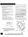
4, Pull all interface wiring in the wall through the opening previously
made. Splice the appropriate wires to the 24-pin interface connector
as indicated in Diagram 1 (Summary of Connections) and in Table C
previously. Insulated solderless wire splices (such as Ademco
No. 311 ) may be used for splicing. Check all wire connections carefully before splicing.
Note
If the optional 15-ft (4.6 m) or 30-ft (9 m) wrong harness has
been used for interface wiring, splices at the Control will not be
necessary since these wiring harnesses are terminated with a
24-pin connector which can be connected directly to the
4130 XT.
5. If a Remote Keypad is being used, splice the field wires in the wall to
the wires on the 10-pin connector supplied for this purpose, being
sure to match wire colors.
6. Attach the interface connector(s)
ring to Diagram 6:
to the Control board as follows, refer-
a. Attach the 24-pin connector to the mating interfacing pins located at
the bottom of the Control board.
b. Attach the 10-pin connector (if a Remote keypad is being used) to
the Remote Keypad connector (1 O-pin socket) at the top of the Control board via the “straight” male-to-male adapter supplied.
IMPORTANT
Be sure to orient the connector with BLACK lead (pin
1) to the left (when viewing the 4t 30XT from the rear),
as indicated in Diagram 1.
7. On the Digital Communication interface board, attach the interconnecting
wires to its terminal block as follows, referring also to Diagram 6:
Communication
Interface
Board Terminal
;
3
4
5
Wire
Assignment
Ground Start ●
Incoming Phone Line (Tip)
Incoming Phone Line (Ring)
Handset (Ring)
Handset (Tip)
●Connect to BLUE lead on 675 Ground Start Module.
Refer to Diagram 9 for Steps 8,9 and 10
8. Mount the Control as follows. Insert securing screw (previously
removed) in screw hole at front of Control (see Diagram 7) and
attach metal clip (at the rear) as shown in Diagram 9. Turn the
screw until the clip enters the guide point about % of an Inch (3 mm)
9, Insert the straight end of the flat spring into the slot at the other
side of the Control, as shown.
II
II
II
II
II
II
II
II
II
II
II
WALL
OPENING
10, With the metal clip in the vertical position, mount the Control by
hooking the spring behind the right edge of the operwng so that It
holds the Control against the inside of the wall, as shown at (A), Now
turn the screw (from the front of the Control). The clip will turn until it
hits the clip stop and will then draw the Control forward (B). Continue
turning the screw until the Control is flush against the wall then, making sure that the Control is straight, tighten the screw further to
secure the Control firmly in position. DO NOT OVERTIGHTENI
1
II
BATTERY
II
II
II
II
II
II
II
II
II
II
II
1,
‘1
1,
II
II
II
BACKBOX
11 Insert the small VISTA XT nameplate supplied into the recessed
opening to cover the screw head at the front of the Control, as previously shown in Diagram 7.
NOTE :
A ROUGH-IN
PRESENT
RING
(4133)
MAY
IN NEW CONSTRUCTION
SIMPLY REMOVE
EXPOSE FRAMEo
FOR FLUSH
BE
IF so,
COVER PLATE TO
OPENING SUITABLE
MOUNTING
OF THE CONTROL,
I
I
I
I
I
I
wsT”Os
I
I
I
i
~~,
‘+.
Diagram 8. WALL PREPARATION
BACK’BOX
I
,,
‘“..
FOR FLUSH MOUNTING
I
A
METAL
CLIP
SPRING
SHEETROCK
(NOTE
END)
B
IF SHEETROCK
IS TOO THICK,
BREAK OFF THE SCORED WING
NOTE :
4-5/16’’(11
cm)H X 7-3/4’’(2Ocm)
WALL OPENING }S REQUIRED
FLUSH MOUNTING.
Diagram 9. FLUSH MOUNTING
THE 4130XT/4137/4147
W
FOR
Installer options are stored in non-removable, electrically erasable, nonvolatile EEPROM memory. These options must be programmed for the
particular installation to establish its specific alarm and reporting
feat ures.
The security control may be programmed from its own keypad (the most
convenient method) or from an optional 4137 or 4157 remote console, or
can be programmed locally from the 699 Programmer. Information
regarding the Programmer is included with the No. 695-30XT Programming Cartridge.
The system is factory-programmed
to a set of preset values, which can
be altered by the Installer to suit the specific needs of a parhcular installation or installation company. The preset values are detatled (n the Factory Programming Table.
Nottz Programming mformatlon E stored In non-volatlle EEPROM
memory in this Control (removal of power WIII not result in the loss
of the information). Consequently, it is possible to program the
Control at any time – even at the installer’s premises prior to the
actual installation. Simply apply DC power temporarily to the Control and then program the unit as desired.
When programming
from the Control, note the following”
1, Enter the Programming mode by simultaneously depressing the * and
# keys within 30 seconds after power is applied to the Control, or subsequently by keying the code 4 + 1 + 3 + O followed by depression of
CODE + O + O keys. Once an Installer code is programmed, use it
instead of 4130 (as 4130 is no longer present) to gain access to the
programming mode.
2 When a data tleld has been completely programmed, the Control WIII
“beep” three times and then automatically proceed to, and display, the
next data field address to be programmed.
3 If the number of dlglts that yob enter In the data field IS less than the
maximum permitted (for example, phone number), then the Control wit
display the last data entered. To proceed, the next data field address
to be programmed must then be entered (for example, *OS).
4 If an address is lm~ro~erly entered, the Control will discday FC. If a
program entry IS rnprope~ly entered (for example, a larger number
than that which is permitted), the Control display WIII go blank. In
either case, simply re-enter the number.
The followlng IS a description
of commands
necessary for programming,
FUNCTION
PROCEDURE
ENTER PROGRAMMING MODE:
1. POWER UP, then depress *and #simultaneouslywithln 30 seconds of powering up.
OR
+3+ OPIUSCODE
key+O+O.
2 Initially, Key:4+l
OR
3 After Installer Code IS programmed, key”
Installer Code + CODE key + O + O.
Notes: User #l (Installer) must be enabled (in
Address 52) if Type 3 method of entry Isto
be used.
Type 3 method of re-entry to the programming mode is inhibited if the programming mode E, exited vla use of *98
Type 1 method of entry can always
be used unless console programming
has been locked out by the remote
downloader.
EXIT PROGRAMMING MODE:
*99 (always allows re-entry to programming
mode via Type 3 entry method above).
*98 (inhibits re-entry to programming
Type 3 entry method),
mode via
Note When the programming mode is exited, a
1-minute set-up period must elapse before
the system can properly function
ADVANCE
PROGRAM
TO FIELD:
FIELD:
* + ADDRESS (e.g., 01, 10, 21, etc.).
* + ADDRESS, followed
by data entries.
ERASE FIELDS:
*+ ADDRESS+ * (only applies to Addresses 31
thru 34),
READ FIELD:
# + ADDRESS
RESTORE FACTORY
PROGRAM SETTINGS
*97
SPECIAL
(see Factory Programming
Table).
MESSAGES
OC = OPEN CIRCUIT (no communication between the Keypad and the
Control, most relevant to4137 or4157 Remote Console).
FC = FIELD CODE ERROR (program entry mistake, re-enter the data).
After powering up, READY will be displayed after approximately 7
seconds. Enter the programming mode by simultaneously depressing *
and # within 30 seconds. The System is factory-programmed
with preset
values (see Table D) that can be altered via the programming instructions that follow the table.
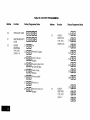
FACTORY
PRESET VALUES
Factory preset values serve two purposes:
●
●
They can reduce programming time on the part of the installer if many
of the preset values shown in the table are accepted.
They will permit an installer who is unfamiliar with this product to
quickly set up the system for bench test so that familiarity with the
operation of the system can be achieved in a shorter period of time.
The factory preset values are defined in the Table that follows:
Address
Function
Factory Programmed
00
INSTALLER
01
MASTER SECURllY
CODE
02
ASSIGN
RESPONSE
TYPE FOR
ZONES 1-8
Value
c EIml
CODE
Address
Function
Factory Programmed
4
r
Z1
1
03
ASSIGN
RESPONSE
TYPE FOR
ZONES 9-16
04
ASSIGN
RESPONSE
11’PE FOR
ZONE 17
EIEIEI
❑
❑
E❑
❑
o
g
Fire
o
s
Perimeter, Burglary
()
4
anterior, Follower,
Burglary
~
s
Trouble by Day/Alarm
by Night, Burglary
~
anterior, Delay,
Burglary
❑
❑
❑
7
24-hour audtble
~
24-hour Aux
1
Entry /Exit (Delay #l),
Burglary
E
Z2
E
23
24
E
‘n
dmzl
EIEI
Emil
Value
Address
Function
Factory
%ogrammed
Value
o
co El
07
o
❑
o
❑
o
❑
o
El
05
06
ASSIGN
RESPONSE
lYPE FOR
VARIOUS
KEYPAD PANICS
AND ZONE
EXPANDER WIRING
SUPERVISION
DESIGNATE RIGHT
ZONE USAGE
Address
Function
Factory Programmed
DESIGNATE RIGHT
ZONE USAGE
•1
0
Zone17
NOT USED
09
ENTRY
DELAY #1
Elm (’oseconds)
10
EXIT
DELAY #1
EIEI ‘45sec0nds)
11
ENTRY
DELAY #2
Em (’oseconds)
EinEI
“2°‘ec”nds)
❑o
12
EXIT
DELAY #2
20
o
El
13
ALARM SOUNDER
DURATION
3~
E
o
❑
14
ALARM SOUNDER
SELECTION
40
E
0
,0
15
KEYSWITCH ARMI
DISARM ENABLE
Short in Wiring to Zone
Expander (displays “97”)
16
CONFIRMATION
OF ARMING DING
17
AC POWER
LOSS SOUNDING
18
NOT USED
19
CONTROL ALARM
SOUNDER DISABLE
O (Enable)
•1
20
NOT USED
❑
‘rim
❑
❑
❑
❑
‘
n
1 and * Panic (displays
,,)
7
D
3#;’panic(disp’ays
8
m
* and # Panic (displays
,,)
Hmmmmm
Zones 10-16 (none)
(none)
08
10
r
c
Value
Em
❑
❑
❑
•1
❑
“min”’es~
o
(740/bell
O
(Disable)
o
(Disable)
O
(Disable)
0
(Entry of zero mandatory)
o
compatibility)
(Entry of zero mandatory)
Address
Factory Programmed
Function
21
DISABLE FIRE
TIME-OUT
22
FIRE INDICATION
ON DISPLAY
23
MULTIPLE ALARMS
24
TAMPER DETECTION DISABLE
(ZONES 10-1 7)
Value
SECONDARY
PHONE NO
No Entry
35
CS DOWNLOAD
PHONE NO
No Entry
❑
❑
36
CS ID NO
37
DOWNLOAD COMMAND ENABLES
1
(Yes)
o
(Enable)
❑
(Loud steady sound, UL Listed
usage)
TEST REPORT
INTERVAL
❑
(24 hours)
28
POWER UP IN
PREVIOUS STATE
1
•1
(Yes)
29
QUICK
❑
(Enabled)
26
INTERNAL ALARM
SOUND
SELECTION
27
ARM
30
TOUCH-TONE
OR
ROTARY DIAL
31
PABX ACCESS
CODE
32
SUBSCRIBER
ACCT NO.
PRIMARY
PHONE “No.
33
Factory Programmed
34
❑
DURESS REPORT
DISABLE (ADEMCO
HIGH SPEED)
Function
o (No)
•1
1 (Enable)
El
(Enable)
25
Address
o
o
1
2
1
n
I
5
6
INHIBIT BYPASS
OF ZONE
Hmm
HmEmEmH
Dialer Shutdown enabled
,“
System Shutdown
enabled
Not Used
1
Remote Bypass enabled
1
Remote Disarm enabled
❑
1
7 •11
8
(Touch-Tone)
No Entry
n
mHHm
1
31
4
2
❑
❑
❑
❑
❑
❑
Value
❑
❑
,
Remote Arm enabled
Upload Program enabled
Download Program
enabled
m
~:::;;;:)’ones
Address
Function
Factory Programmed
Vaiue
Address
OPEN/CLOSE
REPORTING
ENABLE BY
USER CODE
EIEZIEIEIEIIEIEI
40
REPROGRAM/
DOWNLOAD
ATTEMPT REPORT
Em
41
EOLR DISABLE
(Zones 2-8)
❑1
o
❑
39
(disabled for Users 9-1 5)
42
DIAL TONE PAUSE
43
DIAL TONE
DETECTION
44
RING DETECTION
COUNT
45
PRIMARY ACK
WAIT
46
PRIMARY TRANSMISSION FORMAT
47
SECONDARY
WAIT
48
SECONDARY
TRANSMISSION
FORMAT
49
(Nocoderepofled)
(End-of,-Line Resisto(
superwslon not required)
ACK
SINGLE MESSAGE
TRANSMISSION
WITH CHECKSUM
VERIFICATION
❑o
❑
❑
❑
❑
0
(30 seconds)
O
(Ademco Low Speed)
o
(30 seconds)
o
(Ademco Low Speed)
o
(No)
Enabled)
(Ring detection disabled)
o
❑
51
52
‘
Factory Programmed
Value
SESCOA/RADIONICS SELECTION
❑
Radionics with B-F reporting
DUAL REPORTING
n
(No)
OPEN/CLOSE
REPORTING
ENABLE BY
USER CODE
IzElmmmmmm
0
(disabled for Users 2-8)
❑
53
4+2 ZONE
EXPANDED FORMAT SELECTION
54
4+2 ZONE FORMAT SELECTION
55
ALARM
56
RESTORE REPORT
57
BYPASS REPORT
58
TROUBLE
59
OPEN/CLOSE
REPORT
❑
❑
❑
❑
60
LOW BATTERY,
AC LOSS AND
TEST REPORT
(5 seconds)
1 (Dial Tone Detection
El
O
50
Function
REPORT
REPORT
O
(Not selected)
o (Not selected)
El
O (Standard report)
El
1
(Expanded)
o
(Standard report)
O
(Standard report)
o
(Standard report)
❑
(Standard report)
o
Address
61
Function
CHANNEL
ASSIGNED TO
EACH ZONE
Factory Programmed
Value
Zeroes for zones l-8 (no
code reported)
,mm
,EIEI
JIIEI
,EIEI
,EIEI
6~~
Sm
,Eilm
62
CHANNEL
ASSIGNED TO
EACH ZONE
(CONTINUED)
IDE
,mm
,Hm
JIIEI
,EIEI
Address
Zeroes for zones 9-16 (no
code reported)
Function
Factory Programmed
fj~~
,EIEI
&ml
63
Value
Address
64
Function
CHANNELS
ASSIGNED TO
DURESS AND
VARIOUS KEYPAD
PANICS
Factory Programmed
Tim
‘Em
All zeroes in 8 locations
‘Em (same as Address *61)
‘Em Duress
Short on Wiring to Zone
‘Em Expander (displays 97)
1 and * Panic
%ml (displays 95)
3 and # Pantc
7mil (d!splays 96)
8~~1
65
ALARM REPORTING CODES
ASSIGNED TO
EACH CHANNEL
Value
‘mm
* and # Panic
(displays 99)
Zeroes for channels 1-8
(no code reported)
‘mm
8mm
4EIEII
Address
Function
Factory Programmed
Vstue
‘Elm
6EIII!ZI
‘Em
8Em
66
ALARM REPORTING CODES
ASSIGNED TO
EACH CHANNEL
(CONT’D)
Zeroes for channels
‘IZIEI(no
code reported)
l’EIEI
11Em
‘21ZIEI
‘3Em
“Eml
‘5EIEI
Em
NOT USED
9-15
Address
67
Function
Factory Programmed
NON-ALARM
CODES
H
❑
m
NON-ALARM
CODES (CONT’D)
69
ZONE TYPES 1-4
RESTORE REPORT
ENABLE
❑
70
ZONE TYPES 5-8
RESTORE REPORT
ENABLE
•~~~
71
72
73
❑
68
All zeroes (no codes
,.,..,,,
,
1
FORMAT ZONES
1-8 EVENT
DIGIT (Ist digit)
2~
0
3 ~~
Factory Programmed
4 + 2 EXPANDED
1 •~AL
FORMAT ZONES
9-16 EVENT
DIGIT (lst digit)
2 •~TR
Value
Zeroes for zones 9-16 (m
codes reported)
3~~lBY
0 AL RE
1
nnm
‘nab’e
(a”)
~~~~l~dall
others dlaabled
1
❑❑
❑
4 + 2 EXPANDED
Function
All zeroes (no codes
repo,e,)
❑❑
zoNETYPEs9&lo
RESTORE REPORT
ENABLE
Address
Value
✎
t)
AL
0
TR
~[
74
Enabled (all)
BY
4 + 2 EXPANDED
FORMAT ZONE
17 EVENT
DIGIT (1 SI digit)
TR RE
30
BY RE
I0
TR
3o
B’i
la
2~
❑
30
40
Zeroes for zones 1-8 (no
codes reported)
30
El J0 AL RE
5~~TRRE
Zeroes for zone 17 (no
codes reported)
Address
75
76
Function
4 + 2 EXPANDED
FORMAT KEYPAD
PANICS/ZONE
EXPANDER WIRING
SUPERVISORY
EVENT DIGIT
(1st digit)
4 + 2 E)(pANDED
FORMAT ZONES
1-8 ID DIGIT
(2nd digit)
Factory Programmed
Value
Address
77
Zeroes for keypad panics and
for zone expander wiring
supervisory (no codes
reported)
m—
3101101BY
~[TR
6 ~1
~1
4 + 2 EXPANDED
FORMAT ZONES
9-16 ID DIGIT
(2nd digit)
Factory Programmed
9 ~1
Value
F[
lomm
11 ~F[
dml
4 •~ALRE
5 ~1
Function
RE
BY RE
14 ~
l@lE
16HH
~1
Zeroes for zones 9-16 (no
codes reported)
Address
78
Function
4 + 2 EXPANDED
FORMAT ZONE
17 ID DIGIT
(2nd digit)
Factory Programmed
17
Value
Address
Function
o
o
El
o
•1
79
4 + 2 EXPANDED
FORMAT KEYPAD
PANICS/ZONE
EXPANDER WIRING
SUPERVISORY ID
DIGIT f2nd diait)
-,
80
rmq
——
❑Ou1171
–
Em
4 + 2 EXpANDED
FORMAT NONALARM CODES
Hn
‘Uress
1 &*
Panic
3&#
Panic
* &# Panic
Zeroes for zone 17 and the
other seven locations (no
codes reported)
❑o
Valua
Short in wiring to zone
expander
o
0 El
•1
❑o
❑ IIo
❑o
Factory Programmed
Zeroes (no codes
reported)
in all 10 Iocatlons
Address
81
Function
Address
4 + 2 EXpANDED
FORMAT NONALARM CODES
(CONTINUED)
82
ALARM
COUNT
83
84
Function
TEST REPORT
INITIATION TIME
ADEMCO HIGH
SPEED REPORTING ON 800/WATS
LINES
Factory Programmed
Value
EIEI‘12h0urs)
85
ENABLE 4130XT
FOR SUBZONING
o
❑
❑o
86
ZONE EXPANDER
TYPE SELECTION
❑
1
(No)
(Disabled)
(4208 type selected)
SPECIFIC
ADDRESS
PROGRAMMING
INSTRUCTIONS
ADDRESS
FUNCTION
INSTALLER
CODE
*OO
❑ nnn
COMMENTS: This 4-digit (O-9) code reserved for Installation company use. Only active if openings and closings are
enabled for User #1 (in Address *52). This IS the only code that can be used to enter the Program mode from the
Control. Cannot be used to enter secondary codes This code may not be used if programming mode is exited by a ●98.
MASTER
CODE
SECURITY
ASSIGN RESPONSE
TYPES FOR ZONES
1-8
*OI
❑
000
COMMENTS:
feature.
*O2
Enter 4 digits, O-9 (entry of all 4 IS mandatory). Use of a “9” In last position inhibits the Ambush
❑
❑
❑
❑ o ‘one’
❑ o ‘0ne4
❑ n ‘one’
❑ o ‘one’
❑ l ‘one”
❑ o ‘one’
0
‘one’
n
‘0ne2
n
‘one’
COMMENTS Enter 2 digits, 00-10 in each field
(use one of the response types below).
‘If Zone 7 is to be used for Keyswitch Arm/Disarm
10 must be entered as its response type.
00 =
01 =
02 =
03 =
04 =
05 =
06=
07 =
08=
09 =
10 =
operation,
Assign for unused zones
ENTRY/EXIT (Delay #1), Burglary
ENTRY/EXIT (Delay #2), Burglary
PERIMETER, Burglary
INTERIOR, FOLLOWER, Burglary
TROUBLE BY DAY/ALARM BY NIGHT, Burglary
24-HOUR SILENT
24-HOUR AUDIBLE
24-HOUR AUXILIARY
FIRE
INTERIOR, DELAY, Burglary
FUNCTION
ASSIGN RESPONSE
TYPES FOR ZONES
9-16
FUNCTION
ADDRESS
*O3
,mm
2UUZonelCl
8
❑
1
EEl
4
❑
Zonell
0
Zcme12
5UUZcme13
fjUUZcme14
7
❑
U
Zone15
8UUZone16
*O4
COMMENTS: Enter
response type in field
lUUZone9
3Cln
ASSIGN RESPONSE
TYPE FOR ZONE 17
ADDRESS
ASSIGN RESPONSE
*O6
TYPES FOR ZONE
EXPANDER WIRiNG
SUPERVISORY AND
FOR KEYPAD PANICS
a
::t~a’t~:-~in
dzlm
LID
Zeros to be entered
4EIEII
,cln
Short m Wiring to Zone
Expander (displays 97)
600
1 & * Panic (displays 95)
COMMENTS: Enter 2-di@ response types
(see Address *O2 for types)
700
3 & # Panic (displays 96)
lURZone17
8CICI
* & # Panic (displays 99)
COMMENTS: Enter response types
(see Address *02 for types)
in field locations 5-8 only
(enter 00 in fields 1-4).
2mm
JImI
4EIEI
Zeroes to be entered
5EIEI
rmlr!zl
ADDRESS
FUNCTION
10
DESIGNATE
RIGHT
ZONE USAGE
*06
❑
11
12
13
14
15
16
lnmlmlzoneslo-16
17
*Q7
•1
Zone 17
COMMENTS: All spaces must be filled with O or 1 (1 if that zone is a right loop on a 4190WH transponder or on a
4196 Quad PIR transponder). When the 4208 E used as a Zone Expander, set all zone number locations to O. Similarly, set the zone number Iocatlons for 4194WH contact/transponders,
4192 smoke detector base/transponders,
and 4275 Dual PIR transponders to O, as well as left loops on 4190WHS and the PIR portion of the 4196.
NOT
*o6
USED
ENTRY
DELAY
#1
*Q9
❑o
COMMENTS: Defines the time per!od between a fault occurring In a zone to which Entry Delay #1 has been
assigned and the time when the alarm will sound (UL 1023 Household Burglary usage permits a maximum of 45
seconds. ) Applies to the Interior, Delay Zone type also
Enter 00-15. Multiply by 15 seconds to determine time delay (O- 225 seconds available).
EXIT DELAY
#1
*1Q
❑
o
COMMENTS: Defines the time delay period after the system arming code IS keyed when zone to which this delay
has been assigned will arm (UL 1023 Household Burglary usage permits a maximum of 60 seconds). Is also the
exit delay time allocated to the Interior zones (both Follower and Delay types).
Enter 00-15.
Multiply by 15 seconds to determine time delay (O-225 seconds available).
FUNCTION
ENTRY
ADDRESS
DELAY
#2
*11
❑o
COMMENTS: Defines the time period between a fault occurring [n a zone to which Entry Delay #2 has been
assigned and the time when the alarm will sound, (UL 1023 Household Burglary usage permits a maximum of 45
seconds,) Must be set for longer pariod than Entry Delay #1 (in Address *09).
Enter 00-15. Multiply by 15 seconds to determine time delay (O-225 seconds available).
EXIT DELAY
#2
*12
Em
COMMENTS: Defines the time delay period after the system arming code is keyed when zone to which this delay
has been assigned will arm. (UL 1023 Household Burglary usage permits a maximum of 60 seconds).
Must be set for longer period than Exit Delay #1 (in Address *1 O).
Enter 00-15.
Multiply by 15 seconds to determine time delay (O-225 seconds available).
ALARM SOUNDER
DURATION
“13
ALARM SOUNDER
SELECTION
●14
KEYSWITCH
ARMI
DISARM ENABLE
●15
❑l
COMMENTS: Defines the length of time an external or the control’s alarm sounder will sound on all audible alarms
(UL 1023 Household Burglary usage requires a minimum of 4 minutes).
Enter 01-15. Multiply by 2 minutes to determine sounder duration.
❑
COMMENTS: Enter O for use with Ademco 740 or BRK BK-PA400B piezoelectric
or ABB-1 031 12V Motor Bell or for external relay activation. Do not enter “l”.
sounder, or AMSECO MSB-1 OG
•1
COMMENTS: Requires the use of zone 7 wired loop (zone 7 no longer available as protection zone when used for
keyswitch operation).
Enter 1 for keyswitch enabl~ otherwise, enter O. NOTE: 10 must have been entered for Zone 7 in Address ’02.
Reports opening/closing
by user #7 if reporting is enabled in Address ’52.
FUNCTION
ADDRESS
CONFIRMATION
ARMING OING
ENABLE
AC POWER
SOUNOING
NOT
LOSS
●I6
❑
COMMENTS: Enter 1 to enable 1/2 second external alarm sounding at the end of exit delay #1 and O to disable
the “ding”,
●17
•1
COMMENTS: Enter 1 to enable this feature. Results in rapid beeping at Control when AC power is lost; otherwise,
enter 0.
’18
USED
CONTROL
SOUNDER
NOT
OF
ALARM
DISABLE
USED
●19
Em
❑
MUST BE ZERO
COMMENTS
*2O
DISABLE FIRE
TIME-OUT
●2I
FIRE INDICATION
AT DISPLAY
●22
❑
❑
0
Enter 1 to drs.able the built-in sounder during a burglary, otherwise enter O.
MUST BE ZERO
COMMENTS: Disables the sounder time-out feature for any zone designated as a fire zone so that fire sounding
continues until fhe system is reset (required for usage in accordance with UL985, Household Fire). Enter O (timeout) or 1 (no time-out).
•1
COMMENTS: Enables a display of FIRE (or FI at 41 57) whenever a fire alarm occurs When the alarm is silenced
or times out, the FI display at the 4157 IS replaced by zone number. Enter 1 to enable;, otherwise enter O (only
zone number displayed).
ADDRESS
FUNCTION
MULTIPLE
ALARMS
●23
❑
COMMENTS: Enables the system to permit mutiple audible alarms from a protection zone during one armed interval (as opposed to only one alarm).
Enter O (only one alarm) or 1 (multiple alarms, but not more frequently than allowed by alarm time-out) Selection
has no impact on the number of communciation messages transmitted.
DISABLE TAMPER
DETECTION
IN
EXPANSION
ZONES
10-17
*24
DISABLE DURESS
REPORTING
IN
ADEMCO HIGH
SPEED FORMAT
●25
INTERNAL ALARM
SOUND SELECTION
“26
TEST REPORT
INTERVAL
*27
❑
COMMENTS: Only applicable if No, 4190WH RPMs are used to provide expansion zones. Enter 1 to disable
tamper detection (disables tamper detection in 4190WH or tamper detection is not applicable because other
devices are used to provide expansion zones), Enter O to enable tamper detection (opening of the 4190WH case).
❑
COMMENTS: Only applicable
to enable duress reporting.
if Ademco High Speed Format is selected. Enter 1 to disable duress reporting or O
•1
COMMENTS: Enter 1 to select a ‘(sweeping” sound (applicable only to non-UL usage) from the control’s internal
alarm sounder, enter O for a louder, steady sound (required for UL Listed usage).
NOTE: Since remote Consoles can only produce a “steady” sound, program the control for steady tone (0) if they
are used in the system.
❑
COMMENTS: Determines time period between test reports.
Enter O (no report), or 1 (12 hours), 2 (24 hours)or3(168
hours).
Must be used in conjunction with Data Fields *83 and *68 (location 5), Select a non-zero entrv if automatic low bat.
tery testing under load is desired.
ADDRESS
FUNCTION
POWER UP IN
PREVIOUS
STATE
●28
QUICK
●29
ARM
❑
COMMENTS: If selected (YES), on power-up the system w(II assume system status prior to power down. If not
selected (NO), the system w(II power up in disarmed state.
Enter O (NO) or 1 (YES),
When the system powers up armed, an alarm WIII occur 3 minutes after arming If a zone is faulted, When so
armed, reports closing as User #7 if open/close reporting for User #7 was enabled in Address *52.
❑
COMMENTS: Enables arming of the burglary system in any mode without use of a Security Code (just # key
depression followed by the command AWAY, STAY, INSTANT or MAXIMUM). When armed AWAY or MAXIMUM,
reports closing as User #7 (f open/close reporting for User #7 was enabled m Address *52,
Enter O (disabled) or 1 (enabled).
TOUCH-TONE
OR
ROTARY DIAL
PABX ACCESS
●3O
CODE*31
•1
COMMENTS: Permits selection of the type of dialing to be used.
Enter 1 for Touch-Tone, O for Rotary.
❑0
❑0
❑0
❑0
COMMENTS: If not required, enter nothing and proceed to next address; otherwise, enter prefix needed to obtain
an outside Telco line. This field may be used alternatively to enter a prefix that can suppress the Telco’s call waiting feature from interfering with outgoing transmission. This prefix is only useful if the Telco option to be able to
suppress call waiting has been obtained by your customer. The prefix to be used is 1170 if pulse dialing is being
used or *7O if TouchTone@ dialing is being used
Enter up to 4 digits, Each digit requires a 2-digit entrj so as to allow entry of hexadecimal digits (B-F) Use the following chart to determine the entry for each dlglt. Only enter digits required Do not fill unused spaces. Erase the
field by entering *31*.
-—-
— —.
-.
ADDRESS
FUNCTION
NUMBER
o
1
2
3
4
5
6
SUBSCRIBER
ACCT. NO.
*32
❑0
❑0
❑
0
ENTER
00
01
02
03
04
05
06
07
NUMBER
8
9
A
B
c
D
E
F
ENTER
08
(Do N% Use)
11
12
13
14
15
00
COMMENTS: Enter 3 or 4 digits. Each digit requries a 2-digit entry so as to allow entry of hexadecimal digits (B-F)
If entry consists of only 3 digits, enter data in the first 6 locations, leaving the last two unfilled. Use the chart in
address *31 to determine the entry for each digit. Erase the field by entering *32*
❑
*33
00000000000
COMMENTS: Enter up to 12 digits, O-9. Do not fill unused spaces. Erase the field by entering *33*. NOTE: Backup reporting (8 calls are made to the secondary phone number If no acknowledgment is received after 8 attempts
to the primary number) is automatic only if there is a secondary phone number
SECONDARY
PHONE hJo.
*34
lclclclnnnnnnclcl
COMMENTS: Enter up to 12 digits, O-9. Do not fill unused spaces. Erase the field by entering *34*.
CENTRAL STATION
DOWNLOAD
PHONE
No.
*35
nuclnclonnclcln
COMMENTS: Only applicable if downloading
Erase the field by entering *35*
CENTRAL STATION
ID NUMBER
*36
PRIMARY
PHONE
No.
❑
❑
❑
O
COMMENTS:
00=0
01=1
❑
❑
❑
will be utilized. Enter up to 12 digits, O-9. Do not fill unused spaces.
❑
❑
❑
❑
0
o
0
n
n
n
0
Only apphcable If downloading will be utilized. Enter all 8 hexadecimal digits. (O-9, A-F).
02’2
03=3
04=4
05=5
06=6
07=7
08=8
09=9
10=A
ll=B
12=C
13=D
14=E
15=F
FUNCTION
DOWNLOAD
COMMAND
ADDRESS
*37
1
ENABLES
2
❑
❑
Dialer Shutdown
System Shutdown
3 •10
Not Used
4
Remote Bypass
5
6
7
❑
❑
❑
❑
8 •1
Remote Disarm
Remote Arm
Upload Program
Download
Program
COMMENTS: Each of the various remote (from the Central Station) functions can either be enabled or disabled,
dependent upon what functions the Central Station desires to perform. Setting a function to be disabled means
that the Central Station will not be able to perform this function in the system. Enter 1 to enable a function and O to
disable a function.
INHIBIT BYPASS
OF ZONE
●3S
❑o
COMMENTS: Enables one zone to be selected as a priority zone which cannot be bypassed. Enter 2 digits (for
zone number) 01-17. Enter 00 if all zones to be bypassable This section has no impact on fire zones, which are
always non-by passable.
FUNCTION
ADDRESS
9
OPE?i/CLOSE
REPORTING
ENABLE
BY USER CODE
*39
11
DISABLE USAGE OF
END-OF-LINE
RESISTOR SUPERVISION ON WIRED
ZONES 2-8
*41
DIAL TONE
*42
12
13
14
15
nnnnnn
COMMENTS:
*4O
REPORTING
CODE
FOR ATTEMPT
(SUCCESSFUL
OR UNSUCCESSFUL)
BY A
REMOTE AGENCY TO
GET INTO A DOWNLOAD MODE WITH
THE SYSTEM OR FOR
SOMEONE TO
LOCALLY CHANGE
THE PROGRAM
PAUSE
❑
10
❑o
Enter O (disable) or 1 (enable). Determines which user codes will send open/close
LOCAL REPROGRAM/DOWNLOAD
COMMENTS: Applicable if downloading
(no code reporting).
01=1
06=6
11=6
02=2
07=7
12=C
03=3
08=8
13=D
04=4
09=9
14=E
05=5
10=0
15=F
reports
ATTEMPT REPORT (1st digit)
will be utilized or not. Enter reporting code as double digits. Disable=
00
Note: If 4+2 by point reporting E being used, the second digit is the second digit of the power up code
❑
COMMENTS. Enter 1 to change zones 2-8 to N.C. loops that detect only an “open” and do not require end-of-line
resistors (EOLRS) Enter O to retain EOLR supervision of zones 2-8.
❑
COMMENTS: This feature determines the wait time for dial tone detection before diallng will commence
tion does not take place.
Enter single digit, O (5 seconds), 1 (11 seconds) or 2 (30 seconds.)
.——... —
If detec
ADDRESS
FUNCTION
DIAL
*43
TONE
DETECTION
❑
COMMENTS:
programmed
where noise
Enter 1 (Dial
RING DETECTION
COUNT
*44
PRIMARY
*45
ACK WAIT
Determines whether true dial tone detection is used, or whether just delay before dialing (same as
in Address *42) is used. The latter may be necessary in high-noise environment Telco networks
can be confused with dial tone and premature dialing results.
Tone Detection) or O (Dial Tone Detection disable),
❑
n
COMMENTS: Only applicable if central station initiated downloading will be used. Enter 00 to disable ring detection. Enter 01-14 for ring counts of 1-14. Enter 15 to select mode that gets around telephone answenng machines
connected to the same phone line. In the latter mode, the system upon hearing one ring followed by nothing, will
not answer but will ready itself to pick up the next incoming call received within the next 30 seconds on the first
ring (the downloader calling again).
❑
COMMENTS: Central Station receiver “Acknowledge”
Enter O (30 seconds) or 1 (60 seconds).
PRIMARY
TRANSMISSION
FORMAT
*46
wait time for primary phone number.
•1
COMMENTS: Permits selection between Ademco Low Speed format, SESCOA/Radlon!cs,
or Ademco High Speed
format.
Enter O (Ademco Low Speed) or 1 (SESCOA/Radionics),
or 2 [Ademco High Speed - Traditional for up to t4 (all
20 if non-unique reporting is acceptable) zones plus duress and 4+2 DTMF for all 21 zones].
Note If Traditional Ademco High Speed reporting is selected, the Non-Alarm reports desired must be selected in
Addresses *40, *67 and *68 and the alarm reports desired must be selected in Addresses *65 and *66
(Any non-zero code may be used).
SECONDARY
WAIT
ACK
*47
❑
COMMENTS: Central Station receiver “Acknowledge”
Enter O (30 seconds) or 1 (60 seconds).
wait time for secondary phone number.
FUNCTION
ADDRESS
SECONDARY
TRANSMISSION
FORMAT
*48
*49
SINGLE MESSAGE
TRANSMISSION
WITH
CHECKSUM
VERIFICATION
SESCOA/RADIONICS
SELECTION
*5O
DUAL
*51
REPORTING
❑
COMMENTS: Same options as Address *46.
Enter O (Ademco Low Speed 1 (SESCOA/Radionics),
or 2 (Ademco High Speed)
•1
COMMENTS: When selected, will send verification digit with the message to validate the message
at the receiver without having to send two message rounds. Enter O (NO) or 1 (YES).
NOTE: Selection applies to both primary and secondary phone numbers,
❑
COMMENTS: Enter O if Radionics format is to be used with hexadecimal B-F reporting; enter 1 if SESCOA format
is to be used with only numenc reporlmg (0-9),
NOTE: Selection applies to both primary and secondary phone numbers.
❑
COMMENTS: If selected, will send all reports to both primary and secondary phone numbers.
NOTE: If dual reporting is desired and Ademco High Speed format is to be used at all, it must be selected as both
the primary and secondary transmission formats
Enter O (NO) or 1 (YES)
OPEN/CLOSE
REPORTING
ENABLE
BY USER CODE
*52
ilbttllxlnn
COMMENTS: Enter O (disable) or 1 (enable) Determines which user code will send open/close reports. User #7
must be enabled if open/close reporting is desired for keyswitch arming or close reporting is desired for “Quick
Arm” and “Power Up” arm.
NOTE: User #1 must be enabled to permit use of installer code to enter programming mode.
FUNCTION
ADDRESS
4+2 ZONE
(MAX.
OF
17 WIRED ZONES)
EXPANDED FORMAT
SELECTION
*53
n
COMMENTS:
Enter 1 if 4+2 reporting by zone for a zone expanded system IS desired, enter O if a non expanded
zone configuration is being used. If the expanded zone reporting format is selected, skip Addresses 55-71 and
continue programming at Address #72.
IMPORTANT
If Ademco High Speed format had been selected in Addresses *46 or *48 and this selection is
made, a high speed 4+2 transmission using DTMF TouchTone@ communication can be obtained which is compatible with Ademco No, 685 Digital Receivers using Level 4.3 software or higher.
4+2 ZONE (MAX. OF 9
WIRED ZONES)
FORMAT SELECTION
*54
•1
COMMENTS:
Enter 1 if 4+2 reporting is desired, enter O If 3+1 /4+1 or traditional Ademco High Speed reporting
is to be used. This selection is overriden by the selection of 4+2 reporting in Address *53. If the 4+2 format of
address *54 is selected, Adresses 55-70 should be programmed, but Addresses 72 through 81 should be
skipped.
The following reports (Addresses *55 - * 60) may be designated to raport aither in Standard or Expanded format. in aii cases, the Standard
message reports to tha Central Station a subscriber ID number and a report [e.g., alarm (see Address *55), trouble, restore, open/ciose] code.
The Expanded message reports a subscriber iD number, the report code, foilowed by a second line where the report code is repeated three or
four times and ia traiied by the chennel number (or user iD) reiated to that report. When 4+2 format is aeiected, no second iine is transmitted.
The channel number or User iD is sent as the last digit of the report.
Report
3+1/4+1
Standard
3+1/4+1
Expanded
Alarm
SSS(S) A
SSS(S) A
4+2
SSSS ACh
Report
3+1/4+1
Standard
3+1/4+1
Expanded
AC
SSS(S) R
SSS(S) R
LOSS
AAA(A) Ch
Trouble
SSS(S) T
Low Battery
SSS(S) R
TTT(T) Ch
Bypass
SSS(S) B
Trouble
SSS(S) E
SSSS EAc
SSS(S) E
SSS(S)RT
SSSS RTCh
SSS(S) RB
RTRTRT(RT)Ch
SSS(S)RB
Bypass
SSSS RBCh
EEE(E) Ac
Low Battery
SSS(S) L
SSS(S) L
RBRBRB(RB)Ch
SSSS LLB
Where,
Ssss Ou
SSS or SSSS = Subscriber ID
A = Alarm Code
L = Low Battery Code ( i st digit)
LB= Low Battery Code (2nd digit)
O = Zero
Ch = Channel Number
O = Open Code
C = Close Code
T = Trouble Code
B = Bypass Code
U = User Number
Te = Test Code
LLL(L) LB
Open
Sss(s) o
Sss(s) o
000(0)
Close
Sss(s) c
u
Ssss Cu
Sss(s) c
ccc(c)
SSSS RLB
SSS(S) RT
BBB(B) Ch
AC LOSS
SSS(S) R
RRR(R) LB
SSSS Etch
SSS(S) B
SSSS RAC
RRR(R) Ac
SSSS TCh
SSS(S) T
4+2
u
Cancel
Sss(s) x
Sss(s) x
Ssss Xo
Test
SSS(S) Te
SSS(S) Te
SSSS TeO
E = AC Loss Code (1st Digit)
AC = AC Loss Code (2nd digit)
R = Restore Code (Alarm,
AC Loss, Low Battery)
Power Up Reset
Sss(s) P
Sss(s)
Ssss Po
X = Cancel Code
RT = Restore Code (Trouble)
Program Tamper
SSS(S) M
SSS(S) M
SSSS MO
P = Power Up Reset Code
RB = Restore Code (Bypass)
P
M = Program Tamper Code
Restore.
Alarm
SSS(S) R
Sss(s) R
RRR(R) Ch
SSSS Rch
Ademco High Speed Format
This format is the fastest format used in the alarm industry in that alarm
information on 8 zones can be received at a Central StatIon in 5 seconds.
This format utilizes DTMF (Touchstone@) signaling and transmits at the
rate of 10 hexadecimal characters per second. The tradlt(onal format of
Ademco High Speed transmission contains 13 digits, as follows: 4 digit
Subscriber ID number, 8 digits containing the status of each of 8 event
reporting channels and 1 digit in a 9th channel that is primarily used to
indicate what kind of event is being received in the other 8 channels,
For the eight event reporting channeis (digits 5-12 in the format), the
channel status codes are as follows:
Code
Meaning
1
2
3
4
5
6
NEW EVENT (previously unreported)
OPENING REPORT
RESTORE
CLOSING REPORT
NORMAL (no event since prewously reported RESTORE)
PREVIOUSLY REPORTED EVENT STILL PRESENT
For the ninth channel (digit 13), the following channel status codes are
used:
1 DURESS REPORT in channel 1 and ZONE ALARM and ALARM RESTORES assigned to CHANNELS 9 through 15 (in Addresses *6 I
through *64) will appear in channels 2 through 7 respectively Channel
8 is not usable.
4 CLOSING REPORT m the prewous 7 or 8 channels; 7 if expanded
opening/closing
reporting is selected, wherein User ID (1 -9, A-F)
appears {n Channel 1
5 ZONE TROUBLE and TROUBLE RESTORE REPORTS for ZONES
assigned to CHANNELS 1 through 8 (In Addresses *61 through *64)
will appear in channels 1 through 8.
6 SYSTEM TROUBLE and TROUBLE RESTORE REPORTS are in the
previous 8 channels; wherein
CH
CH
CH
CH
1
2
3
4
= LOSS Of AC
= Low Battery
= Program Tamper+
= Power On Reset’
CH
CH
CH
CH
5
6
7
8
=
=
=
=
Not
Not
Not
Not
Applicable
Applicable
Applicable
Applicable
‘No Restore report is prouided for these conditions.
7 ZONE ALARM and ALARM RESTORE REPORTS for ZONES assigned
to CHANNELS 1 through 8 (In Addresses *61 through *64) will appear
in channels 1 through 8.
9 TEST REPORT. All ‘5’s WIII appear in channels 1 through 8.
IMPORTANT
NOTES:
1.When the traditional Ademco High Speed format is used, zones
assigned to channels 9 through 15 in Addresses *6 I through *64
cannot report trouble, trouble restore, bypass, and bypass restore As
such, 24 hour type keypad panic zones are good candidates for the
use of these reporting channels (e.g. * & #, 1 & *, 3 & # panics, etc...)
2 OPENING REPORT in the previous 7 or 8 channels; 7 if expanded
opening/closing
reporting is selected, wherein User ID (1 -9, A-F)
appears m Channel 1.
2. Only NEW events ALARM, OPENING, RESTORE, BYPASS, CLOSING
or TROUBLE on any channel or TEST WIII trigger transmission, at
which time all 9 channels will report.
3 BYPASS and BYPASS RESTORE REPORTS for ZONES assigned to
CHANNELS 1 through 8 (in Addresses *61 through *64) will appear in
Channels 1 through 8.
3. When the traditional Ademco High Speed format IS used, non-zero
codes must be entered in Addresses 61, 62, 63, 64 (for zones m
use), 65, 66, 67, 68.
4. After transmission of Example 3, subscriber #0135 sends a closing:
Examples (Ademco High Speed Zone format)
1. At subscriber #5890, channels 2 and 5 go into alarm (and initiate a
call) and channel 6, which has previously reported an alarm is still
triggered.
Message:
Subscriber
Identification
Channel Number
1234
5678
9
5890
5155
Channel 2:
Channel 5:
Channel 6:
1655
7
Subscriber
Identification
Channel Number
1234
5676
9
5890
5355
Channel 2:
Channels 5,6:
6655
NEW RESTORE
PREVIOUSLY REPORTED ALARMS
(still In effect)
Subscriber
Identification
0135
Channel 1.
Channels 2-9:
Channel Number
1234
5678
9
1222
2222
2
USER ID — User #l opened
OPENING REPORT TRANSMITTED
Channel Number
1234
5676
9
0135
D444
Channel 1:
Channels 2-9:
4444
4
USER ID - User#13 (= hex D) closed
CLOSING REPORT TRANSMITTED
5 Subscriber #01 35 sends a duress message:
Subscriber
Identification
0135
Channel 1:
Channel 9:
Channel Number
1234
5676
9
1555
5555
1
DURESS REPORT
SUPPLEMENTAL ALARM ZONES
TRANSMITTED
6 Subscriber #01 35 User #7 bypasses faulted zone 2 (for the sake of
this example, Zone 2 = Channel 3, not a requisite) and then arms the
system.
7
3. Subscriber #0135 sends an opening:
Message:
Message:
NEW ALARM
NEW ALARM
PREVIOUSLY REPORTED ALARM
(still in effect)
2 Still at subscriber #5890, following the events of example 1 above,
channel 2 restores (initiating the ~all) and channels 5 and 6 remain in
alarm
Message”
Subscriber
Identification
Message:
Subscriber
Identification
Channel Number
1234
5676
9
0135
0135
5515
7444
5555
4444
3 (Bypass Report)
4 (Closing Report)
Bypass restorals are transmitted when the restoral takes place
0135
5535
5555
3
7. If a trouble condition occurs in Zone 4 for subscriber #5890 and Zone
4 was assigned 10 Channel 2, a trouble report is transmitted.
Message:
Subscriber
Identification
Channel Number
1234
5676
9
5890
5155
5555
5
Trouble restoral is transmitted as soon as it occurs.
5355
5890
5555
5
8. If a system trouble condition occurs, a separate trouble message format exists.
Channel Number
1234
5678
9
Subscriber
Identification
For Loss olACReporting
Message:
(Channell
0135
5555
8
3555
5555
6
ForLowBattery
Message:
Reporting
5155
5555
FUNCTION
REPORT
ADDRESS
*55
5555
6
0135
5515
5555
6
Message:
0135
5551
5555
6
NOTE: Restorals are not applicable to Program Tamper and Power Up
Reset.
9. At Subscriber #5890, Zone 12 assigned to channel f 3 goes into alarm
and Zonell
assigned tochannel 11, which hasprevlously reported
an alarm has restored.
Subscriber
identification
Channel Number
1234
5678
9
5890
5553
5155
1
10, At Subscriber #0135 a test message is initiated.
6
*Low battery is not only determined when AC power is off and the battery
is being discharged, It is also tested for byperiodically
(at the interval
selected in Address #27) removing ACpower briefly to check battery
status.
ALARM
Message:
(Channel 2 is used)”
0135
5355
For Power Up Reset (Channel 4 is used)
Message:
0135
0135
For Program Tamper (Channel 3 is used)
is used)
1555
For AC Restorai
Message:
For Low Battery Restorai
Message:
Message:
Subscriber
identification
Channei Number
1234
5678
9
0135
5555
5555
9
❑
COMMENTS: Enter O (Standard Report) or 1 (Expanded Report).
When Expanded is selected, the channel number is transmitted in the last position of the 2nd transmission line (or
of the lsttransmission line if4+2 Format is used).
NOTE: Selection applies to both primary and secondary phone numbers.
FUNCTION
RESTORE
ADDRESS
REPORT
*56
❑
COMMENTS: Enter O (Standard Report) or 1 (Expanded Report).
When a zone of protection alarm, bypass or trouble report is transmitted, a restore report for any of those conditions is not issued unless ALL like conditions within a zone are restored.
When Expanded is selected, the channel number is transmitted in the last position of the 2nd transmission line (of
the 1st transmission line if 4+2 Format is used). Restore reports for each zone type alarm are individually selectable (see Address numbers *69 through *7f ),
NOTE: Selection applies to both primary and secondary phone numbers,
BYPASS
REPORT
*57
❑
COMMENTS: Enter O (Standard Report) or 1 (Expanded Report).
Bypassing a zone results in a bypass report and in a restore report when all bypasses are removed.
Fire and priority zones cannot be bypassed, When Expanded is selected, the channel is transmitted in the last
position of the 2nd transmission line (or of the last transmission line if 4+2 Format is used). Zone ID is not
transmitted.
NOTE: Selection applies to both primary and secondary phone numbers.
TROUBLE
REPORT
*58
•1
COMMENTS: Enter O (Standard Report) or 1 (Expanded Report).
When Expanded is selected, the channel is transmitted in the last position of the 2nd transmission
1st transmission line if 4+2 Format is used). Zone ID is not transmitted.
NOTE: Selection applies to both primary and secondary phone numbers.
OPEN/CLOSE
REPORT
*59
line (or of the
❑
COMMENTS Enter O (Standard Report) or 1 (Expanded Report).
When Expanded is selected, user ID (1 -9, A-F) is transmitted in the last position of the 2nd transmission
the Ist transmission line if 4+2 Format is used).
NOTE: Selection applies to both primary and secondary phone numbers.
line (or of
FUNCTION
ADDRESS
FUNCTION
LOW BATTERY,
AC LOSS AND
TEST REPORT
*6O
CHANNEL
TO EACH
*61
ASSIGNED
ZONE
ADDRESS
❑
COMMENTS: Enter O (Standard Report) or 1 (Expanded Report).
When Expanded is selected, an additional programmable code is transmitted
mission line (of the 1st transmission line if 4+2 Format is used).
NOTE: Selection applies to both primary and secondary phone numbers.
2
3
4
5
6
7
8
NOTE: Channel 9 (09) is reserved
for duress reporting when that
function is enabled in Address *25.
CHANNEL
ASSIGNED
*62
TO EACH ZONE (CONT’D)
❑ U Zone2
❑U
❑
❑
❑
❑
❑
in the last position of the 2nd trans-
l130Zone9
2UDZone10
.Zone3
30
0
Zone4
4
U
Zone5
5uDZone13
m
Zone6
6
0
Zone7
7UDZone15
O
Zone8
8Dn
COMMENTS” Enter all channel
IDs as double digits.
Disable = 00 (no channel reporting)
01=1
02=2
03=3
04=4
05=5
06=6
07=7
08=8
09=9
10=0
il=B
12=C
13=D
14=E
15=F
UZonell
❑
❑
0
n
.Zone12
Zone14
Zone16
COMMENTS: Enter all channel IDs
as double digits (same as Address
*61 ) Disable = 00 (no channel
reporting).
NOTE: Channel 9 (09) s reserved
for duress reporting when that
funcllon IS enabled m Address *25
FUNCTION
CHANNEL
TO EACH
(CONT’D)
FUNCTION
ADDRESS
ASSIGNED
ZONE
*63
100
Zone17
2 •~
Not”,,,
3 •~
Not Used
CHANNEL
TO EACH
(CONT’D)
ADDRtSs
ASSIGNED
ZONE
*64
1 •~
Not used
2 ~~
Not.sed
4
5 •~
Not used
❑o
Dure.s
5nn
Short on Wlr!ng
to Zone Expander
60U
1 & * Pamc
7UU3&#Panm
a
EIEI
N.tused
COMMENTS: Enter all channel IDs
as double digits
(same as Address *61).
Disable =00 (no channel reporting).
NOTE: Channel 9 (09) is reserved
for duress reporting when that
function is enabled in Address *25
COMMENTS: Enier all channel IDs
as double dlglts
(same as Address *6 I )
Disable = 00 (no channel reporting),
Non-zero codes must be
entered when Iradlllonal Ademco High
Speed format IS used.
NOTE: Channel 9 (09) is reserved
for duress reporting when that
function IS enabled in Address *25,
FUNCTION
ALARM REPORTING
CODES ASSIGNED
TO EACH CHANNEL
FUNCTION
ADDRESS
*65
,00
ALARM REPORTING
CODES ASSIGNED
TO EACH CHANNEL
(CONT’D)
200
3CICI
4CICI
5CICI
ADDRESS
*66
900
IOouo
,Slcl.
12 CICIC
Karl.
6CICI
S3n
LID,
lam
8EIU
COMMENTS: Enter all alarm reporting
codes as double digits.
Disable =00 (no code reporting).
Note Non-zero codes must be
entered when traditional Ademco High
Speed format is used
01=1
02=2
03=3
04=4
05=5
06=6
07=7
08=8
09=9
10=0
ll=B
12=C
13=D
14=E
15=F
COMMENTS: Enter all alarm reporting
codes as double digits
(same as Address *65).
Disable = 00 (no code reporting).
Note: Non-zero codes must be
entered when traditional Ademco High S!
format IS used.
FUNCTION
NON-ALARM
ADDRESS
CODES
*67
FUNCTION
❑n
❑l
❑
❑
❑
❑
❑
ml-(x,
AC LOSS 2ND DIGIT
0
TROUBLE
n
TROUBLE RESTORE
o
BYPASS
0
B~PASS RESTORE
n
RESTORE CODE FOR ALARM,
AC LOSS, LOW BATTERY
COMMENTS: Enter all codes as double
digits (same as Address *65).
Disable =00 (no report).
Note: Non-zero codes must be
entered when traditional Ademco High
Speed format IS used.
NON-ALARM
CODES
*66
❑o
❑
o
*68
(CONT’D)
ADDRESS
❑
❑
❑
❑
❑o
❑ ●
n
LOW BATTERY
n
LOW BATTERY 2ND DIGIT
o
TEST
0
‘POWER UP 1
NOT USED
o
CANCEL CODE 2
COMMENTS: Enter all codes as double digits (same as Address *65).
Disable =00 (no reporl).
Note: Non-zero codes must be entered when traditional Ademco High
Speed format is used.
*When 4+2 format is used, the 2nd digit of the event code is always “0”
NOTES:
] After a power reset, or after exiting the Program mode, this code will be
sent.
Z If system is shut down by using a security code while a burglary alarm is
sounding, this code will be sent. (Not sent for 24-hour zones).
OPEN
CLOSE
A Cancel in traditional Ademco High Speed format is the same as an
Opening Report for user 15 and should not be used together.
ADDRESS
FUNCTION
To disable
Restore
reports, program all locations in Addressee *69 -*71
ZONE TYPES 1-4
RESTORE REPORT
ENABLE
*,,
ZONE TYPES 5-8
RESTORE REPORT
ENABLE
*,O
0000
(See Address *O2 for Response types)
COMMENTS: Enables Restore reporting for individual zone types. Enter 1 to select restore reporting for the zone
type: enter O to inhibit restore reports.
Unl%l
(See Address *O2 for Response types),
COMMENTS: Enables Restore reporting forlndividual
type; enter O to inhibit restore reports
9
ZONE TYPES 9 AND
10 RESTORE REPORT
ENABLE
INTRODUCTION
as “O”.
*71
❑
zone types Enter ltoselect
restore reporting forthe zone
10
n
(See Address *O2 for Response types).
COMMENTS. Enables Restore reporting forindlvldual zone types. Enter ltoselect
type; enter O to inhibit restore reports,
TO FIELD ADDRESSES
72-81
restore reportmgfor the zone
NOTES:
In order to make it easier for an installer to understand expanded zone
reporting, an explanation and an illustrative example are given first.
1, Two-digit entries are required because hexadecimal
allowed (O-9, B-F) = (00-15) for fields 72-81
entries are
Bearing in mind that a 2-digit reporting code is utilized, let us discuss
how zones 1-17, Duress, Zone Expander Supervisory, and the 3 keypad
panics (1 & *, 3 &#, and * &#) can be coded. The recurring theme of
the following information is that the leading digit represents the type of
event being reported and the second digit identifies the zone within that
type.
2 Users of the Ademco CAPS Automation System are cautioned not to
assign 78 or 8C for any report, as these codes are reserved.
3 If Ademco High Speed Format IS selected in either Addresses *46
or *48 and the 4+2 Expanded Zone Format is selected in Address
*53, a very fast 4+2 Format is created that uses DTMF (Touchstone@)
signalllng instead of pulses. Actually, 9 digits are transmitted but only
the 4+2 portion of the message is ever seen on the central station
receiver’s display or printer. This High Speed 4+2 format is currently
only compatible with Ademco No. 685 Digital Receiver operating with
Revision 4.3 software or higher and has a message transmission
of well under 5 seconds.
EXAMPLE:
An example of code assignments
Zone
2
3
4
5
6
7
8
9
10
11
12
13
14
15
16
17
Duress
Zone Expander
Supervisory
1 & * Panic
3 & # Panic
* & # Panic
IS given below:
Alarm
Trouble
Bypass
Bypass
Restore
Restore
Restore
;:
22
23
24
25
26
27
28
10
29
2B
::
36
37
39
41
42
43
44
45
46
47
48
30
49
4B
51
52
53
54
55
56
57
59
61
62
63
64
65
66
67
68
50
69
5B
71
72
73
74
75
76
77
79
81
82
83
84
85
86
87
88
70
89
8B
91
92
93
94
95
96
97
99
01
02
03
04
05
06
07
08
90
09
OB
DI
D2
D3
D4
D5
D6
D7
D9
El
E2
E3
E4
E5
E6
E7
E8
DO
E9
EB
2D
2E
2F
4D
4E
4F
5D
5E
5F
8D
8E
8F
OD
OE
OF
ED
EE
EF
Alarm
11
12
13
14
15
16
17
Trouble
31
32
33
time
NOTES:
4. English language on the Ademco 685 Digital Receiver should not be used for most of these reports
5. Note that B and C are not used for leading digts m the above table. It is suggested that these digits be reserved for use in reporting
“openings” and “closings” so that the appropriate display and print out can be obtained at the central station receiver and so that an
au!omat~on system can be given the appropriate information
FUNCTION
4+2 ExpANDED
FORMAT ZONES
1-8 EVENT DIGIT
(Ist digjt of
reporting code)
ADDRESS
*72
FUNCTION
❑
❑
❑
❑
❑
❑
CIALARM
4+2 ExpANDED
n
TROUBLE
m
BYPASS
FORMAT ZONES
9-16 EVENT DIGIT
(lst digit of
reporting code)
n
ALARM RESTORE
n
TROUBLE RESTORE
n
BYPASS RESTORE
COMMENTS: The firs! digit of the 2
digit event code used to report
alarm, trouble, bypass and their restores for zones 1-8. Enter all reporf ing codes asdoubledigits
(see
Address *65). Disable =00 (no code
reporting)
ADDRESS
*73
❑
❑
❑
❑
❑
❑
UALARM
0
TROUBLE
0
,,,,,s
n
ALARM RESTORE
n
TROUBLE RESTORE
n
BYPASS RESTORE
COMMENTS:The firstdigitofthe2
digit event code used to report
alarm, trouble, bypass and their restores for zones 9-16. Enter all repotiing codes asdoubledigits (see
Address *65) Disable =OO(no code
reporting)
FUNCTION
4+2 EXPANDED
FORMAT ZONE
EVENT DIGIT
(Ist digit of
reporting code)
FUNCTION
ADDRESS
*74
17
❑
❑
❑
❑
❑
❑
n
ALARM
lcl
TROUBLE
n
BYPASS
n
ALARM RESTORE
n
TROUBLE RESTORE
n
BYPASS RESTORE
COMMENTS: The first digit of the 2
digit event code used to report
alarm, trouble, bypass and their restores for zone 17. Enter all reporting
codes as double digits (see Address
*65). Disable = 00 (no code
reporting)
4+2 EXPANDED
FORMAT KEYPAD
PANICS/ZONE
EXPANDER WIRING
SUPERVISORY
EVENT
DIGIT (Ist digit
of reporting code)
*75
❑
❑
❑
❑
❑
o
ALARM
n
TROUBLE
n
BYPASS
n
ALARM RESTORE
n
TROUBLE RESTORE
ADDRESS
❑o
*75
(CONT’D)
4+2 Ej(pANDED
FORMAT ZONES
1-8 ID DIGIT
(2nd digit of
reporting code)
BYPASS RESTORE
COMMENTS: The first digit of the 2
digit event code used to report
alarm, trouble, bypass and their
restores for various keypad panics
(duress, * &#, 1 &*, and 3 & #) and
for supervision of the wiring (for
short circuits) to the zone expander.
Enter all reporting codes as double
digits (see Address *65). Disable =
00 (no code reporting).
*76
Z1
Z2
Z3
Z4
Z5
Z6
Z7
Z8
❑
❑
❑
❑
❑o
❑l
❑
❑
n
0
n
n
n
u
COMMENTS The second dtglt
of the 2 dlglt event code used
to report alarm, trouble, bypass
and their restores for zones 1-8
Enter all reporting codes as
double dlglts (see Address
*65). Disable = 00 (no code
reporting)
FUNCTION
4+2 EXPANDED
FORMAT ZONES
9-16 ID DIGIT
(2nd digit of
reporting code)
ADDRESS
*77
FUNCTION
Z9
❑
n
Zloncl
*II
❑
u
4+2 EXPANDED
FORMAT ZONE
17 ID DIGIT
(2nd digit of
reporting code)
ADDRESS
*78
mnn
Eim
ImII
Z1213cl
•~
moo
Elm
Z14UU
z15nn
z16ncl
COMMENTS: The second dig!t of
the 2 digit event code used to report
alarm, trouble, bypass and their
restores for zones 9-16. Enter all
reporting codes as double digits
(see Address *65). Disable =00 (no
code reporting)
Zeroes to reentered
EIEI
Em
Em
COMMENTS: The second digit of
the 2 digit event code used to report
alarm, trouble, bypass and their
restores for zone 17. Enter the
reporting code as a double digit (see
Address *65) in the first field
Iocallon (enter 00 in the other seven
fields) Disable = 00 (no code
reporting)
FUNCTION
4+2 EXPANDED
FORMAT KEYPAD
PANICS/ZONE
EXPANDER
WIRING
SUPERVISORY
ID
DIGIT (2nd digit
of reporting
code
ADDRESS
*79
FUNCTION
EIEI
4+2 EXPANDED
EIEIZeroes to be entered
ImI
❑ U Duress
❑o
❑
❑o
o
ADDRESS
Short in Wiring to
Zone Expander
1 & * Panic
3 & # Panic
cm *
& #
p~ni~
COMMENTS: The second digit of
the 2 digit event code used to
report alarm, trouble, bypass and
their restores for various keypad
panics (duress, * &#, 1 &*, and 3
&#) and for supervision of the
wiring (for short circuits) to the
zone expander. Enter all reporting
codes as double digits (see
Address *65). Disable = 00 (no
code reporting).
FORMAT
CODES
NON-ALARM
*8CI
❑
❑
❑
❑
❑
❑
❑
❑l
❑
❑o
D
CLOSE REPORT (1st digit)
n
CLOSE REPORT (2nd digit)
n
OPEN REPORT (1st digit)
0
OPEN REPORT (2nd digit)
0
LOW BATT REPORT (1 S1digit)
n
LOW BATT REPORT
(2nd digit)
ln
LOW BATT RESTORE
REPORT (1 St dlait)
0
‘ “
LOW BATT RESTORE
REPORT (2nd digit)
TEST REPORT (1st d!git)
TEST REPORT (2nd digit)
COMMENTS:
● Enter all reporting
codes as double
digits (see Address *65).
Disable =00 (no code reporting)7T
both Ist and 2nd digits are
so programmed
● 1st digit of Close Report must be C
(hex 12) if English printout of
FUNCTION
ADDRESS
●
●
4+2 EXPANDED
FORMAT NON-ALARM
CODES (CONT’D)
*81
“close” E desired on Ademco No. 685 Recewer or if closlng by
user is to be processed on an Ademco AutomatIon System
1st digit of Open Report must be B (hex 11 ) if English printout of
“open” is desired on Ademco No. 685 Receiver or if opemng by
user is to be processed on an Ademco Automation System.
The 2nd digit of both the Close and Open Reports represents
the user ID for the Installation Company Security Code. User
No. 2 is automatically assigned an ID one higher than this code
(e.g., if 01 is keyed, User 2 reports as 2, User 3 as 3, etc...)
❑o
❑o
POWER UP REPORT (1 st digit)
POWER UP/DOWNLOAD
ATTEMPT REPORT CODES (2nd digit)
Izn AC LOSS REPORT (1 St dglt)
❑ ln AC LOSS REPORT (2nd digit)
❑o
cm
Em
Em
❑0
❑0
AC RESTORE REPORT (1st digit)
AC RESTORE REPORT
(2nd digit)
Not used Zeroes to be Entered
COMMENTS:
Power Up E transmitted after a power reset or after exiting the
Program Mode.
o Cancel is transmitted if system is shut down while a burglary
alarm is sounding.
. Enter all reporting codes as double digits (see Address *65).
Disable = 00 (no code reporting) if both 1st and 2nd digits are
so programmed
●
Not used Zeroes to be Entered
CANCEL REPORT (1st dig[t)
CANCEL REPORT (2nd digit)
FUNCTION
ALARM
ADDRESS
COUNT
*82
❑o
COMMENTS: Enter 01-15.
This option limits the number of messages Alarms or Troubles) sent for a specific channel in an
armed period (Swinger Suppression) before additional reports from that channel are inhibited. This
selection is system-wide.
TEST REPORT
INITIATION
TIME
*83
❑
n
COMMENTS: Enter the time in hours from the time that the programming mode is exited that the
first test report shall be transmitted. 00 entry signifies immediately upon exiting. 01-31 represents
the range in hours that can be selected,
ADEMCO HIGH SPEED
FORMAT USED ON
WATS LINES
●84
DO NOT
’85
USE
❑
COMMENTS: Enter 1 if Ademco High Speed Format (either traditional or 4+2 versions) will be
transmitted on 800/WATS lines where satellite links may be used. Enter O if other formats are
selected or if local telco lines are being used.
•10
MUST BE ZERO
COMMENTS: This field is otherwise used for subzone control enable. It is recommended
4130NI be used to perform that function instead, for monetary savings.
ZONE EXPANDER
TYPE SELECTION
*86
that a
❑
COMMENTS: Enter 1 if No. 4208 Eight Zone Expander is being used. Enter O if other VECTOR type
RPMs are being used to expand the number of zones. Imporianti
See the section on an earlier page
entftled “Zone Expansion” for proper configuration of the No. 4208.
After installation
tested.
is completed, the Security System should be carefully
1. With the System in the disarmed state, check that all zones are intact.
If NOT READY is displayed, press READY key to display the faulted
zone(s). Restore faulted zone (s) if necessary, so that READY is
displayed.
2. Enter the security code and press the TEST key The external
sounder (if used) should sound for 3 seconds and then turn off (the
system is operating on the back-up battery only at this time).
Note 1. The system will not enter the TEST mode, (f the battery voltage is too low, if Ihe battery is not connected, or if any communication messages are pending their transmission.
Note 2. As a reminder that the system is in the TEST mode, the Control will sound a single beep at 15-second intervals if no protection zones are violated.
Note 3. In the TEST mode, no reports will be sent to the central station.
Note 4. In TEST mode, the external sounder (if used) will not activate
3. Doors and windows: Open and close each protected door and
window in turn. Each action should produce three beeps from the
Control. The identification numbers for each protection zone WIII
aPPear on the Control display,
4. Motion detector=
Walk in front of any interior motion detectors (if
used). Lislen for three beeps when the detector senses movement
While it is activated, its identification number will remain displayed on
the Control.
5, Smoke detectors: Follow the test procedure provided by the manufacturer of each smoke detector to ensure that all detectors are operational and are functioning properly. Note: A Zone 1 2-wire smoke
detector display will not clear until the Test mode is exited.
6. To turn off the TEST mode, enter the security code and press the
OFF key.
A message WIII be sent to the central station during the following tests.
No(lfy the central station that a lest will be in progress
NOTE: A display of “FC mdlcates a failure to communicate (no Kissoff
by the receiver at the central sta~ion after the maximum number
of transmleslon attempts is tried).
7 Arm the system and fault one or more zones.”Silence alarm sounder(s)
each time by entering the code and pressing OFF. Check Entry/Exit
delay zones
8 Check the keypad-initiated alarms by simultaneously pressing the
Panic keys (* and #, land *, and/or 3 and #). If the system has been
programmed for audible emergency, the Control will emit a loud,
steady alarm sound, and ALARM and “99” will be displayed for * and
# (if 1 and * are pressed, “95” wdl be displayed; If 3 and # are
pressed, “96” will be dmplayed). Silence the alarm by entering the
security code and pressing OFF.
If the system has been programmed for silent emergency, there will be
no audible alarms or displays, but a report will be sent to the central
station.
Notify the central station that all tests are finished, and verify results with
them.
1. Fully explain the operation of the System to the user by going over
each of its functions as well as the User’s Manual supplied.
2. In particular, explain the operalion of each zone (entry/exit, perimeter,
interior, fire, etc.). Be sure the user understands how to operate any
Emergency feature(s) programmed into the System. Important In the
spaces provided m the User’s Manual, record the Entry and Exil Delay
times, and those functions that have been programmed into the available pairs of “Emergency” keys (* and #, 1 and *, 3 and #).
3. Make sure the user understands the importance of testing the system
at least weekly, following the procedure provided in the User’s Manual,
TO THE INSTALLER
Regular
maintenance
are vital to continuous
The installer
should
and inspection
(at least annually)
by the installer
and frequent
testing
bytheuser
satisfactory
operation
of any alarm
system.
assume
the responsibility
of developing
and offering
a regular
maintenance
program
to the user as well as acquainting
the user with the proper
operation
and limitations
of the
alarm system
and its component
parts. Recommendations
must be included
for a specific
program
of
frequent
testing
(at least weekly)
to insure the system’s
proper
operation
at all times.
The system will store up to 10 days worth of alarm and trouble messages
for display to service personnel w!th the following procedure:
Enter” Security
Code plus O
The system’s alarm memory retains all events for a period of 10 days,
starting with the iirst event that occurs. Upon expiration of the 10-day
period, all history IS automatically erased and the alarm memory wdl
reset, However, the 10-day cycle will start again only when the next
event occwa.
Recall by service personnel (using the entry indicated above) w(II display
all events that have occurred from the start of the 10-day cycle to the
time of recall (recall always terminates a 10-day cycle). The LCD display
on the Control will indicate the number of the zone in which the event
occurred (e.g., 01, 02, etc,), accompanied by the appearance of the word
CHECK (trouble), ALARM and, if applicable, FIRE, to describe the type
of event that occurred in the displayed zone. If more than one event had
occurred, the events wtll be displayed in zone sequence Each dtsplay
will appear for 1-2 seconds, then disappear.
When all information has been displayed and noted, the recall mode is
exited by entering:
Security Code plus OFF
At this point, ail exsting memory is erased and the alarm memory is
reset. The 10-day cycle will start again only when the next event occurs.
Two fuses (Battery fuse and Auxiliary Power fuse) are located on Ihe
underside of the mam circuit board in the 4130 XT, To replace either of
these fuses, proceed as follows”
away from the board to release their hold on one side of the board,
and ease the board out, away from the three small plastic clasps on
the other s!de.
1. Remove the4130XT from ltsback cover (lf present) The4130XTls
released by removing the screw under the namepiate on the front
panel (see Diag 7)
6 The two fuses are located on the underside of the main clrcwt board
in the posftions shown I!) Diagram 10. Make sure that the fuses are
Inserted tn their correct Iocat]ons Use exact replacements only.
2. If installed, temporarily remove the optional No. 4152LM Laop Module
(Diagram 5 shows assembly details). Removal of the Comrnunlcations Interface board is not necessary.
7 To re-install the board, insert one edge of the board into the notches
In the three smaller plast!c clasps f{rst, then push the other side of the
board down so that the two larger clasps snap mto place over the
edge of the board, holdlng it In place. Make sure that all keys clear
the openings in the front panel and can operate freely.
3. Remove the 24-pin interface connector (f[eld wlnng) To facilitate
removal, squeeze the tab at top of connector and pull outward wlfh a
side-to-side “rocking” motion.
4. Remove the 10-pin Remote Keypad connector
(if used)
5 To remove the 4130XT’S main circuit board, first remove the single
securing screw shown in Diagram 10 (adjacent to the Remote Keypad mlerface). Then pull each of the two flexible plastlc “clasps”
8. Insert the screw (prewously removed) to secure the board lmportank It is essential that this screw be replaced.
9. Re-install the No. 4152LM Loop Module (if removed previously)
10. Reconnect the 10-ptn Remote Keypad connector (If used), the 24-pin
interface connector, and attach the 4130XT 10 Its back cover (If used).
VIEW A
t’
SOUNDER
BATTERY
FUSE
2A ,SLO% LO\
AUK
OSA
&
FUSES
LOCATED
P’
,\
FUSE
,w>s,
,mx,
VIEW
A I
Note: Fuse types used (5 x 20mm European style) are not readily available from electrical supply house and should be Inventoried by the
installer by pre-ordering from Ademco. Alternatively, these fuses are
available at Radio Shack stores.
\
FLEX,
CLASPS
Diagram 10. REMOVING
THE MAIN CIRCUIT
BOARO
ELE PLA$T,
(2 THIS
C
S! DE,
BOARD FOR FUSE REPLACEMENT
4171XT
Part No.
Digital Communication
DC Power Pack -11 OV AC Input, 18V DC
Output (700 mA max output)
SA4131 -10
No, 1350
1O-Pm Connector (for 4131 /41 47)
[with 12“ (30 cm) flying leads]
Aux Power Fuse (k Amp)
No. 90-25
No.
13-Pin Male-to-Male
(41 71XT to 4130XT
N3322-I 3
Battery Fuse (2 Amp, slo-blo)’
Description
Trim Ring (for covering
Plastic Standoffs
(for mounting
10-Pin Male-to-Male
24-Pin Connector
No.
No.
No.
No.
No.
4137
4157
4131
4132
4132-1
No. 4133
No.
4134-8
No. 4134-15
No. 4136
No. 4141-30
overcut
walls)
4171 XT)
Adapter-straight
(for4131 /41 47)
[with 18“ (46 cm) leads]
90-24
N3724
N4062-1
N3707-I O
SA41 30-10
Remote VISTA Console
Remote VECTOR Console.
Remote Keypad.
Battery Backbox,
Cover for Battery Backbox, required for
UL Listed installations,
Rough-in Ring.
8“ x 8“ x 2“ (20 cm x 20 cm x 5 cm) Metal Cabinet
12” x 12” X 3“ (30 cm x 30 cm x 7.5 cm)
Metal Cabinet
Cover Plate for Rough-In Ring, Stainless Steel.
24-Pin Connector with 30’ (9 m) wiring harness.
Interface
Board
Adapter
interface)
No,
Battery (12V, 1.2 AH)
No. 484
(YUASA NPI212)
12“ (30 cm) Battery Leads, Red & Black
SA41 30-4
Front Panel Inserl [VISTA XT Logo)
N3043-3
No. 4141-15
Same as above, but with 15’ (4.6 m) wiring harness.
No. 4~43
Extender Ring for surface mounting 4130XT control
with No. 4171 XT Communication
Interface board.
No. 4147
No. 740
Remote Keypad, VISTA look alike
High Intensity Alarm Sounder (for outdoor use,
mount in No. 742BE Box).
Relay Module. 28 amp rated SPDT contacts
Zone Expander Interface.
8-Zone Expander.
Piezoelectric Sounder, 90dB output, mounts m
single-gang box.
3A SLO-BLO No. 4148 Relay Module fuse
No. 4148
No.
4152LM
No.
4208
BRK PA400B
No. 90-28
“FEDERAL COMMUNICATIONS
This equipment
has been tested
statement
for your information:
to FCC requirements
COMMISSION (FCC) STATEMENT”
and has been found
acceptable
for use. The FCC requires
the following
This equipment generates and uses radio frequency energy and if not installed and used properly, that is, in strict accordance with
the manufacturer’s instructions may cause interference to radio and television reception. It has been type tested and found to
comply with the limits for a Class B computing device in accordance with the specifications in Subpart J of Part 15 of FCC Rules,
which are designed to provide reasonable protection against such interference in a residential installation. However, there is no
guarantee that interference will not occur in a particular installation. If this equipment does cause interference to radio or television
reception, which can be determined by turning the equipment off and on, the user is encouraged to try to correct the interference
by one or more of the following measures:
● If using an indoor antenna, have a quality outdoor antenna installed.
● Reorient the receiving antenna until interference is reduced or eliminated
● Move the receiver away from the control/communicator.
● Move the antenna leads away from any wire runs to the control/communicator.
● plug the Control/Communicator
into a different outlet so that it and the receiver are on different branch circuits.
If necessary, the user should consult the dealer or an experienced radio/television
technician
Commission
The user may find the following booklet prepared by the Federal Communications
“HOW to Identify
This booklet
and Resolve
is available
Radio-TV
Interference
from the U.S. Government
IN THE
EVENT
helpful:
Problems.”
Printing
OF
for additional suggestions.
Office,
TELEPHONE
In the event of terephone operational
problems, disconnect the control/communicator
by removing the plug from the RJ31X/RJ32X jack.
We recommend
that the installer demonstrate
disconnecting
the
phones on Installation
of the system. Do not disconnect the phone
connection inside the control/communicator.
Doing so will result in
the loss of the phone fines. If the regular phone works correctly after
the control/communicator
has been disconnected from the phone
Washington,
DC 20402
OPERATIONAL
Stock
No. 004-000-00345-4.
PROBLEMS
Iines, the control/communicator
has a problem and should be
returned for repair.
If upon disconnection
of the control/communicator,
there is still a
“problem on your line, notify the telephone company that they have a
problem and request prompt repair service. The user may not under
any circumstances (in or out of warranty) attempt any service or
repairs on the system. It must be returned to the factory or an
authorized service agency for all repairs.
4130XT SECURITY
CONTROL:
1. Physical:
Width:
Height:
Depth
2. Electrical
VOLTAGE
INPUT:
RECHARGEABLE
BACK-UP BATTERY:
ALARM SOUNDER”
4171XT DIGITAL
8.4 inches (21.3 cm)
4.75 inches (12.l cm)
1.1 inches (2.8 cm)
Ademco High Spead, 10 characters/see,
DTMF (Touchstone@)
Data Tones, 1400/2300 Hz ACK, 1400 Hz
KISSOFF
Ademco Low Speed, 10 pulses/see,
1900Hz Data Tone, 1400 Hz ACK/
KISSOFF.
SESCOA, 20 puises/see, 1800Hz Data
Tone, 2300 Hz ACK/KISSOFF,
Variable
Interdigit Timing (Use for code reports O-9)
Built-in piezoelectric sounder; 85 db at 10
feet. Sound produced is selectable as
“steady” (in compliance with UL 85db
output requirement) or “sweeping” (for nonUL usage).
Optional dry contact relay (2.8 A max. contact
rahng @ 28V DC), Ademco No. 4148. Can
drive No. 719 or No. 702 siren.
10.4 -13.8 VDC (200 mA MAX., 280 mA for
non-UL usage)
STANDBY:
2.5 Hours with 200 mA standby current
load. 5 Hours with no external current load.
FUSES:
Battery Fuse: 2 A, SIO-BIO (Ademco No.
90-24)
Auxiliary Power: 0.5 A (Ademco No. 90-25)
BOARD:
FORMATS SUPPORTED:
2. Functional:
12 VDC, 1.2 AH (Yuasa NP1212 or Ademco
No. 484) (alternatively, a 4 AH Ademco No
486 may be used).
Optional 12V motor-driven Bell
(100ma max.)
(AMSECO MSB1O-G or ABB-1031 ).
INTERFACE
5-?4” (1 4,8 cm) x 3-%” (8,25 cm) x 7/8”
(2,2 cm) (approx.)
18 VDC (from plug-in Power Pack,
Ademco No. 1350), 700 mA max
Optional external 12V Piezo-electric
alarm sounder (100 mA max). (Ademco No.
740 or BRK PA400B).
AUXILIARY
POWER OUTPUT:
COMMUNICATION
1. Physical:
RADIONICS,
20 puises/see, 1800 Hz
Data Tone, 2300 Hz ACK/ KISSOFF. Fixed
Interdigit Timing (Use for code reports
O-9, B-F).
Line Seize:
Double
Ringer Equivalence:
0.7B
FCC Registration
AC 398 U-681 92-AL-E
4137 REMOTE
No.:
Pole
CONSOLE
1. Physical:
Width:
Height:
Depth
2. Electrical:
Voltage
Current
8.4 inches (21.3 cm)
4.75 inches (12 1 cm)
1.1 inches (2,8 cm)
Input:
Drain:
12V DC (and optionally
100 mA
18VDC)
3. Intertace
W\ring:
12 VDC input (+) —auxiliary
power or for battery backup
power if No. 1350 is used to
separately power the
Console(s).
18V DC input (+) —
Optional, power from (+) output
of separate No. 1350 Power
Pack.
Data in
Data Out
Ground (aiso connects to (-) output of optional
No 1350
Power Pack above)
RED:
BLUE:
GREEN:
YELLOW:
BLACK:
4157 REMOTE
REMOTE
Width:
Height:
Depth:
2. Electrical
Voltage
Current
Wiring
RED:
GREEN:
YELLOW:
BLACK:
WHITE:
2. Electrical:
Voltage Input
Current Dram:
Ground
Auxiliary Sounder (No 706-1 2)
(optional)
(+) connection
5VDC
20 mA
Note Maximum of fwe 4131 4147 keypads
can be supported.
3. Interface
Wiring
1
2
3
4
5
(BLACK):
(wHITE):
(RED):
(GRAY):
(GREEN):
6 (BLUE):
7
8
9
10
12V DC
120 rmA
12V DC input power
Data In
Data Out
4147
84” [21.3 cm)
475” (12.1 cm)
1,1” (2.8 cm)
4131
2-%” (73 cm)
4-Shi’(11 7 cm)
1” (,2.5 cm)
Width:
Height:
Depth:
6-%” (16.5 Cm)
4“ (10.2 cm)
1“ (2.5 cm)
input:
Drain:
KEYPAD:
1. Physical:
CONSOLE:
1. Physicel:
3. Interface
4131/4147
(YELLOW):
(BROWN)’
(VIOLET):
(ORANGE):
Keypad OL >Ut
Keypad Ot YJt
Keypad O\ out
Keypad 0[ 2ut
Keypad Ot yut, RED LED
Arming status
Keypad Output, GREEN LED
Ready status
Keypad Output
+5VDC @20 mA Input Power
Piezoelectric Sounder Input
Ground
4152LM LOOP MODULE
Width:
Hetght’
Depth:
voltage Output:
1. Physicak
(Overall)
2. Electrical
Current Output:
3. Intertace
Wiring:
Terminal 1:
Terminal 2:
3-K” (8 cm)
5/6” (1.6 cm)
2-5/8” (6.7 cm}
7-11 volts [w/l
Modulation)
65 mA
:.;
;;
KHz
4. Wiring
Run Permitted
VECTOR
to No. 4208 Zone Expander
Wire Gauge
Max. Wire Run
22
20
18
16
650
950
1500
2400
(0.64 mm O.D.)
(0.81 mm O.D,)
(1.0 mm O.D.)
(1 3 mm O.D.)
CABINET
(or other
RPMS):
MOUNTING
ft
ft
ft
ft
(200
(290
(460
(730
m)
m)
m)
m)
THE 4130XT
In buildings using concrete, cinder block or brick wall construction, the
4130XT Security Control can be installed in a wall-mounted metal
cabinet. This cabinet, which measures 8“ (20. 3 cm) W x 8“ (20.3 cm) H
x 2“ (5 cm) D, is available under part No, 4134-8. The 4130XT Control is
mounted in a cut-out in the door of the cabinet, with the function keys,
LEDs and display accessible. The back-up battery is installed within the
cabinet Also available for use within the cabinet are connector blocks
with which the 4130XT’S flying leads can be tied to the interface wiring
(from protection zones, etc.). See Diagram B.
Mounting the 4130XT in the Cabinet
Note that there is a mounting flange on each side of the opening m the
cabinet door.The Control is secured to these flanges with the two selftappmg screws supphed. Positton the Control (wtlh back cover removed)
in the opening and secure as follows, referring to Diagram A.
On the left-hand side, insert the No. 6 x 1” self-tapping screw through the
front of the Control into the left flange as shown, and secure. Do not fully
t!ghten yet.
To secure the right-hand .wde, mserf the No, 4 x %“ self-tapping screw
into the other flange from the rear. and screw into the slot in the plastic
4208 ZONE EXPANDER
1. Physical:
Width
Height:
Depth:
2. Electrical:
Voltage Input
Current Drain:
3-7/8” (9.8 cm)
7“(178 cm)
1-3/8” (3.5 m)
8-11 Volts (w/l
Modulation)
16 mA
KHz
at the rear of the Control, as shown, Making sure the Control is straight,
tighten this screw fully,
Fully tighten the screw on the other side, then insert the VISTA XT nameplate into the recess to cover the screw, as shown in Diagram A.
Mounting Cabinet on Wall:
Four holes have been prowded m the back of the cabinet for mounting
purposes -2 keyhole slots at the top and 2 holes at the bottom. Knockouts are prowded at the sides [% “(2.2cm) diameter], plus one at the rear
[1 -%” (4.5 cm) diameter].
1. If the interface wiring is being brought through the wall, make the
required opening In the wall for the wmrig.
2. Remove the desired knockout m the cabinet to allow entry of the interface wiring.
3. Place the cabinet on the wall m the desired position and mark the locations of the mounting holes.
Note The cabinet may be mounted with only 2 screws at the keyhole
slots, if desired.
4. Drill mounting holes in the wall and insert anchors. Mounl the cabinet
securely to the wall with four (or 2) screws.
INSERT
Wiring Connections:
When the Security Control is cabinet-mounted,
the flylng leads from the
24-pin connector are connected to the interface wires via the terminal
blocks provided, as shown in Diagram B. The 12-volt back-up battery is
also installed in the cabinet, and connected to the appropriate terminals
on TB3, using the two 12-inch (30.5 cm) leads supplied (Red and Black),
as shown. The wiring connections are essentially the same as mdlcaled
in Diagram 1 (Summary of Connections diagram) except for the termmal
blocks shown in Diagram B which are used in place of splices.
NAMEPLATE
INTO REcESSED
AREA ICOVERS SCREW)
r---+
I
II
instructions for connection of the optional Remole Keypad and installationand wiring of the digital communication interface board, 4152LM
Loop Module and 4208 Zone Expander are provided in a previous section of this manual (see Index),
After all wiring connections are completed,
connector into the rear of the Control.
plug the 24-pw interface
~
NO. 6x tSELFTAPPING
5CREW
{INSERT FROM FRONT)
Vl}~
CONTROL
A
~
\FLANGES
INFRONT
DOOR OF CABINET [2)
Diagram A. MOUNTING
IN CABINET
—
No.
i
No. ‘1 X l/~~ELFTAPPING SCREW
IINSERT FROM REAR)
THE 4130XT
4134-8
24. PIN CONNECTOR
(SEE DIAGRAM 1)
GO:?ROL
CABINET
a
T81
1
ORANGE
(No. 4134-8)
o
0
—TB1—
—
TB2 —
~
WHTIRED
ZONE2
PINK
ZONE RETURN
WHTIORANGE
ZONE3
+
WHT/YELLOW
ZONE4
+
TAN
ZONE RETURN
WHTIGREEN
ZONE5
WHTIBLUE
ZONE6
+
ZONE7
+
WI+ TIVIOLET
~
ZONE 1 + (WHEN
NC
SENSORS
ARE USED)
ZONE 1 RETURN
WHT/BROWN
7
+
+
‘=ill
TB2
1
W
, TB3 ,
000
REAR OF
CONTROL
]
=iil!l
?
GRAY
ZONE RETURN
WHT)GRAY
ZONE6
WHT/BLACK
ZONE9
REDIYELLOW
ZONE1
BROWN
EXT. ALARM SQUNDER
+
+
+iWHEN2.WIRE
SMOKE OETECTORSAREUSED)
I –)
RED/BIACK
AUXJREMOTE CONSOLE/EXT
YELLOW
DATA OUT (YELLOW
GREEN
DATA IN (GREEN
VIOLET
GROUNDIAUX
WHITE
EARTH GROUND
ALARM SOUNDER PWR ( + I
REMOTE CONSOLEI
REMOTE CONSOLE)
PVVR ( - )
BLUE
RED/GREEN
BLACK
—~
RED
\
COVER SHOWN
HINGED
OOWNWARD
TB31234
‘m
+-
F==iil===c
1
Diagram B. INTERFACE
I
WIRING
12” BAITERY
LEAOSISUPPLIEO)
TO NO 1350
POWER PACK
WHEN THE CONTROL
IS CABINET
MOUNTED
THE LIMITATIONS
While this system
IS an advanced
design security
system,
WARNING
OF THIS ALARM SYSTEM
It does not offer guaranteed
protection
against
burglary or fire or other
emergency. Any alarm system, whether commercial or residential, is subject to compromise or failure to warn for a variety of
reasons. For example:
● Intruders may gain access through unprotected openings or have the technical sophistication to bypass an alarm sensor or
disconnect an alarm warning device.
● Intrusion detectors (e.g., passive infrared detectors), smoke detectors, and many other sensing devices will not work without
power, Battery operated devices will not work without batteries, with dead batteries, or if the batteries are not put in properly.
Devices powered solely by AC will not work if their AC power supply is cut off for any reason, however briefly,
●
●
A user may not be able to reach a panic or emergency button quickly enough.
While smoke detectors have played a key role in reducing residential fire deaths in the United States, they may not activate or
provide early warning for a variety of reasons in as many as s5°/0 of all fires, according to data published by the Federal
Emergency Management Agency. Some of the reasons smoke detectors used in conjunction with this System may not work
are as follows. Smoke detectors may have been improperly installed and positioned. Smoke detectors may not sense fires that
start where smoke cannot reach the detectors, such as in chimneys, in walls, or roofs, or on the other side of closed doors.
Smoke detectors also may not sense a fire on another level of a residence or building, A second floor detector, for example,
may not sense a first floor or basement fire. Moreover, smoke detectors have sensing limitations. No smoke detector can sense
every kind of fire every time. In general, detectors may not always warn about fires caused by carelessness and safety hazards
like smoking in bed, violent explosions, escaping gas, improper storage of flammable materials, overloaded electrical circuits,
children cJavina with matches, or arson. DerIendino on the nature of the fire and/or the locations of the smoke detectors, the
detector: evbn ;f it operates as anticipated, may no; prowde sufficient warning to allow all occupants to escape in time to
prevent injury or death,
●
Passive Infrared Motion Detectors can only detect intrusion within the designed ranges as diagramed
in their installation
manual. Passive Infrared Detectors do not provide volumetric area protection, They do create multiple beams of protection, and
intrusion can only be detected in unobstructed areas covered by those beams, They cannot detect motion or intrusion that
takes place behind walls, ceilings, floors, closed doors, glass partitions, glass doors, or windows, Mechanical tampering,
masking, painting or spraying of any material on the mirrors, windows or any part of the optical system can reduce their
detection ability. Passive Infrared Detectors sense changes in temperature; however, as the ambient temperature of the
protected area approaches the temperature range of 90° to 150° F, the detection performance can decrease.
● Alarm warning devices such as sirens, bells or horns may not alert people or wake up sleepers if they are located on the other
side of closed or partly open doors. If warning devices sound on a different level of the residence from the bedrooms, then they
are less likely to waken or alert people inside the bedrooms. Even persons who are awake may not hear the warning if the
alarm is muffled from a stereo, radio, air conditioner or other appliance, or by passing traffic, Finally, alarm warning devices,
however loud, may not warn hearing-impaired people or waken deep sleepers.
● Telephone lines needed to transmit alarm signals from a premises to a central monitoring station may be out of service or
temporarily out of service. Telephone lines are also subject to compromise by sophisticated intruders,
● Even if the system responds to the emergency as intended, however, occupants may have insufficient time to protect
themselves from the emergency situation. In the case of a monitored alarm system, authorities may not respond appropriately.
like other electrical
devices, is subject to component
failure. Even though this equipment is designed to last as
. This equipment,
long as 10 years, the electronic components could fail at any time.
The most common cause of an alarm system not functioning when an intrusion or fire occurs is inadequate maintenance. This
alarm system should be tested weekly to make sure all sensors are working properly.
Installing an alarm system may make one eliglble for lower insurance rates, but an alarm system IS not a substitute for
insurance. Homeowners, property owners and renters should continue to act prudently in protecting themselves and continue to
insure their lives and property.
We continue to develop new and improved protection devices. Users of alarm systems owe it to themselves and their loved ones
to learn about these developments,
ADEMCO
ONE YEAR LIMITED WARRANTY
Alarm Device Manufacturing Company, a Division of Pittway Corporation (“Seller”), 165 Eileen Way, Syosset, New York 11791, warrants its security
equipment (the “product”) to be free from defects in materials and workmanship for one year from date of original purchase, under normal use and
service. Seller' sobligation islimited torepairing orreplacing, atitsoption,
free ofcharge forparts, labor, ortransportation,
anypartproven
to be
defective in materials or workmanship under normal use and service. Seller shall have no obligation under this warranty or otherwise if the product is
altered orimproperly
repaired orserviced byanyone other than the Selier lncaseof
defect, contact thesecutity professional who installed and
maintains your security system or the Seller for product repair.
This one year Limited Warra’nty is in lieu of all other express warranties, obligations or liabilities. THERE ARE NO EXPRESS WARRANTIES WHICH
EXTEND BEYOND THE FACE HEREOF. ALL IMPLIED WARRANTIES, OBLIGATIONS OR LIABILITIES MADE BY SELLER IN CONNECTION WITH
THIS PRODUCT, INCLUDING ANY IMPLIED WARRANTY OF MERCHANTABILITY, OR FITNESS FOR A PARTICULAR PURPOSE OR OTHERWISE, ARE LIMITED IN DURATION TO A PERIOD OF ONE YEAR FROM THE DATE OF ORIGINAL PURCHASE, ANY ACTiON FOR BREACH OF
ANY WARRANTY INCLUDING BUT NOT LIMITED TO ANY IMPLIED WARRANTY OF MERCHANTABILITY, MUST BE BROUGHT WITHIN 18
MONTHS FROM DATE OF ORIGINAL PURCHASE. IN NO CASE SHALL SELLER BE LIABLE TO ANYONE FOR ANY CONSEQUENTIAL OR
INCIDENTAL DAMAGES FOR BREACH OF THIS OR ANY OTHER WARRANTY, EXPRESS OR IMPLIED, OR UPON ANY OTHER BASIS OF
LIABILITY WHATSOEVER, EVEN IF THE LOSS OR DAMAGE IS CAUSED BY THE SELLER’S OWN NEGLIGENCE OR FAULT. Some states do not
allow
limitations
on how long an implied warranty lasts or the exclusion or limitation of incidental or consequential
damages, sotheabove limitation
or exclusion may not apply to you.
Seller does not represent that the product may not be compromised or circumvented; that the product will prevent any personal injury or property
loss by burglary, robbery, fire or otherwise; or that the product will In all cases provide adequate warning or protection. Buyer understands that a
properly installed and maintained alarm may only reduce the risk of a burglary, robbery or fire occurring without providing an alarm, but it is not
insurance or a guarantee that such will not occur or that there will be no personal injury or property loss as a result. CONSEQUENTLY, SELLER
SHALL HAVE NO LIABILITY FOR ANY PERSONAL INJURY, PROPERTY DAMAGE OR OTHER LOSS BASED ON A CLAIM THE PRODUCT FAILED
TO GIVE WARNING. However, if Seller is held liable, whether directly or indirectly, for any loss or damage arising under this Limited Warranty or
otherwise, regardless of cause or origin, Seller’s maximum liability shall be the complete and exclusive remedy against Seller. This warranty gives
you specific legal rights, and you may also have other rights which vary from slate to state. No increase or alteration, written or verbal, to this warranty
is authorized.
ALARM
DEVICE
A DIVISION
165 Eileen
N3122.1
10/88
MANUFACTURING
oF
PITTwAY
Way, Syosset,
CO.
cORpoRAT,~~
New York 11791
Copyright ~ 1988 PITTWAY CORPORATION