1
Previous Menu
No. 4140
VISTA AT
SECURITY
SYSTEM
INSTALLATION
INSTRUCTIONS
ADEMCO!
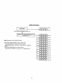
(xMTENTs
General Information ........................................... 2
Remote Programming and Control ................................ 3
Zone Types Available for Selection ............................ 5
Functional Description of Zone Types .......................... 6
Zone Expansion ................................................ 10
4-Digit Security Codes ........................................ 10
Wiring ConnectionsO ........................................... 14
Remote KeysWitch Operation and Wiring ......................... 17
Optional Remote Keypad Connection (4131/4147)................. 17
Installation of No. 4152LM and Wiring to No. 4208..............17
Console Wiring’ Connections (5137 or 4137) ..................... 18
Mounting the Console(s) ...................................... 19
Surface Mounting ........................................... 19
Flush Wall Mounting ........................................ 19
Programming.the Security Control ............. ............*. . 22
Factory Preset Values ........................... .... ..... 24
Specific Address Programming Instructions.............. .... 31
Programming Zone Descriptions
for Display onthe 5137 Console ....................... 55
Creating a Custom Message Display
(Only Usable on 5137 Consoles) ........................ 57
Testing the System ............................................58
5137 LCD Viewing Angle Adjustment. ......................... 59
Using the Built-in Quick-Reference User’s Manusl .............. 60
Turning the System Over to the User ........................... 60
Recalling Alarm and Trouble Messages .......................... 60
Fuses in the 4140 ........ ..... ... ..... ...... ............. 61
Replacement Parts ............................................. 61
Optional Accessories .......................................... 62
FCC Statement ................................................. 63
Specifications ................................................ 64
4140 Security Control...................................... 64
5137/4137 Remote Console .............. ............ ....... 65
4131/4147 Remote Keypad .................................... 65
4152LMZone Expansion Loop Module. ......................... 65
4208 Zone Expander ......................................... 65
The Limitations of this Alarm System .......................... 66
Limited Warranty .............................................. 68
●
●
●
●
●
●
●
●
●
●
●
●
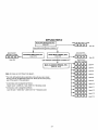
Diagrams
Diagram
Diagram
Diagram
Diagram
Diagram
Diagram
Diagram
1.
2.
3.
4.
5.
6.
7.
Summary of Connections ............................
Keyswitch Wiring ..................................
No. 4152LM Installation and Wiring to 4208 ........
Inserting Nameplate ...............................
Wall Preparation for Flush Mounting ...............
Flush Mounting the 5137/4137/4147 .................
Fuse Location .....................................
Template for Mounting the 5137/4137/4147
16
17
18
20
21
21
61
(provided on separate sheet)
GENERAL INFORMATION
The VISTA AT (No. 4140) is a microprocessor–based
security control which
provides up to 9 wired zones in the basic product, with expansion to an
additional 8 wired zones when connected to a 2-wire zone expansion bus.
The
security control is housed in a wall-mounted metal cabinet measuring 12” (30.5
cm) wide x 12” (30.5 cm) high x 3“ (7.6 cm) deep, and can be used with a console
equipped with a multifunction 12–key digital keypad and a 2-line, 32-character
multipurpose LCD English language display (5137), or one with factory-defined
restricted word LCD display (4137). Both types of consoles are equipped with a
built-in 85 db piezoelectric sounder that meets UL requirements as an alarm
sounder.
Connections to the security control are made via a 24-terminal connector block
which is used to interface to the wired loops, plug-in DC power pack, back-up
battery, remote consoles, external alarm sounder(s), etc. The entire connector
block (with the interface wiring) can be unplugged from the main circuit board
if the board wer needs to be returned for service. Telephone line and optional
ground start module connections are made via a separate 5–terminal connector
block.
The security control can be easily programmed from an optional 5137 (ALPHA
VI~A)
or 4137 (VISTA) remote console; the control can also be programmed
locally from the 699 Programmer (using a 695-30XT cartridge). Programmed options
to establish specific alarm and reporting features are stored in electrically
This means that the unit can be repro–
erasable, non-volatile EEPROM memory.
grammed many times (unlike units equipped with PROMS) and that information which
has been programmed will not be lost in the event of a complete loss of pcwer.
For installer convenience, the control is factory–programmed to a set of values
that is designed to meet the needs of many installations. However, these can be
altered by the installer to suit the specific needs of a particular installation
or installation company, following the instructions provided in the programming
section of this manual (factory-programmed values are also shown there).
This system also contains abbrwiated operating instructions in memory, designed
primarily as an aid to the end user. This feature, which functions only with the
ALPHA VISTA (5137) console, may be used when the system is in the armed or the
disarmed mode, and is activated by simply pressing any of the function keys for
5 seconds. The display on the console will then scroll information related to
the use of that function key.
The system provides communication capability (central station reporting, etc.)
over existing telephone lines, as well as zone expansion connections.
An optional, econanical, remote keypad (4131 or 4147) can be used for arming,
disarming, etc., from a remote indoor location within the protected prenises.
This unit is a compact 12-button keypad with two system status indicators (LEDs)
and a built-in piezoelectric sounder that provides warning sounds. Requires a
10-wire connection to the control.
Remote consoles available for use with the system include:
5137: This console is equipped with 12 backlit keys, a backlit alphanumeric LCD
display, a loud piezoelectric alarm sounder, and requires only a 4–wire
connection to the control.
4137: This console provides functions similar to that of the 5137 with one
notable exception. It utilizes an LCD display that displays numerics for zone
identification and pre-defined words for mode, status, and alarms. Requires only
a 4-wire connection to the control.
This system includes an alarm relay with SPDT dry contacts rated at 2.8 amps.
A ccmplete list of optional accessories will be found in a section toward the
end of this manual under the heading “Optional Accessories” (see Index).
2
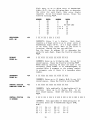
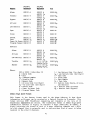
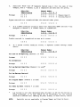
Zone Characteristics
Zone 1:
Programmable
Zone, may be used as EOLR supervised Fire Zone
(supports 2-wire Smoke Detectors), or may be used as a non-fire
zone with N.C. contacts only. 350-500 msec response.
Zones 2–8:
Programmable Zones, EOLR supervised, 350-500 msec response.
Zone 9:
Programmable Zone, N.C. contacts only, fast 10-15 msec response.
Back-up 12V DC Battery
Mounted internally.
YUASA NP412).
Rechargeable
12-volt, 4 AH Lead Acid
(Ademco No. 486 or
DC Puuer Pack
Plug-in Power Pack (DC power converter).
Plugs into unstitched 2-pin 110 volt
AC outlet providing 24–hour service. Power Pack (1350) supplies unregulated
18VDC output (700 mA max.) for powering the Control.
REMOTE PROGRAMMING AND CONTROL
The No. 4140 allows the installer to call it using
so that the control/canmunicator can be remotely
from a No. 699MD Intelligent Programmer or an IBM
(Pc). See Note 2 under Remote Capabilities in this
switched network phone lines
programmed and/or canmanded
compatible Personal Computer
section.
Accessing of the No. 4140 from a remote location is protected against compromise
by someone attempting
to defeat the system, using 4 levels of security
protection:
1.
Security Code Handshake: An 8–digit Central Station ID code must be matched
between the No. 4140 and the Central Station.
2.
Calling the No. 4140 does not directly SI.1OW
Hang-up
and call back:
programming, as a successful handshake merely results in the No. 4140
connection and then calling back the (internally
breaking the phone line
stored) central station service phone number*.
3.
Data passed between the central station and the No.4140
Data Encryption:
is encrypted for security so that it is very difficult for a foreign device
tapped into the phone line to take over canmunication and substitute system
compromising information.
4.
Any condition that causes the system to
Central Station Advisory Note:
number from which it can be
initiate
a call back to a telephone
reprogrammed or commanded (in fact, even for a local reprogramming of the
EEPROM) causes a unique report to be sent to the central station’s alarm
logging digital receiver.
* Note:
In situations where a service person is on site and the system is
installed inside a PABX, it is possible to initiate a download from
the protected premises by keying [installer or master security code] +
[#1 + [11.
3
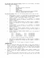
Equipment Required
At the premises:
●
4140
At the central station (or the installer’s office/home):
.
.
A No. 699MD Intelligent Programmer that incorporates an intemd
modem
and a No. 695–30XT Program Cartridge.
OR
An IBM PC compatible computer, a Modem (check with Ademco Factory
Technical Support for the specific brand and model to be used), No.
4130PC Downloading Software Diskette, and appropriate interconnecting
cables.
Remote Capabilities (See Note 2)
Programming:
N1
programming functions accessible from the unit’s keypad or via local
No. 699 direct programming.
handing:
There are two types of commands that can be issued to the system:
1.
Control Ccmmands –
To Arm the System in
,t!~ ‘way Mode’ (1)
To Disarm the System
To Bypass a Zone
TO Force the Systa to Accept a New Program Download
To Shut Down Caumunication (dialer) Functions (non-payment of
monitoring fees in an owner’s system)
To Shut Down all Security System Functions (non–payment for a
leased system)
To Inhibit Local Keypad Programming (prevents takeover of your
accounts)
2.
Status Commands To Cause the Systm to Upload a Copy of its Resident Program to
the central station
To Read System Status:
Arming Status
Ready Status and Current Faults
Presence of Alarms (past or present)
Presence of Troubles (past or present)
AC Power Status
Bypass Status and Current Bypasses
* NOTES:
1.
If the system is programmed for open/close reporting by user, User #7 will
be reported.
2.
After the 4140 and the 699 or PC have established valid communication, each
console will become inactive.
The 4140 will resume the normal security
(including responding to faults that took place during the
functions
See the 4130PC or 695–
downloading) after it is canmanded to hang up.
30XT instructions for details.
4
The detailed
operation of the functions described below is covered in the
Installation Instructions for the No. 695-30XT Program Cartridge and for the
4130PC Download Software Diskette.
—
To
To
To
To
To
To
Read
Read
Read
Read
Read
Read
List of Faulted Sensors
List of Bypassed Sensors
10-Day Alarm History Log
10-Day Trouble History Log
List of Sensors Currently in Alarm
List of Sensors Currently in Trouble
Remote Communication Specifications:
.
.
Program Download Time - 1 minute for a complete program
Typical Total Time Including Call Up/Call-Back - 3-4 minutes.
Remote Coenmand/Progranming Advisory Notes:
.
Alarm and Trouble Reporting are disabled during the time that the system
and the central station are linked to each other for the described
functions, following a valid exchange of codes.
.
Keypad entries are ignored during the same time interval cited above.
.
Should an alarm transpire during the remote program/control interval, the
system would not respond to the alarm condition until the raote mode was
The local zones and the Nos. 4190WH, 4192, 4192SD, 4194WH, 4196,
ended.
4208 and 4275 all store their fault conditions until they are read by the
Control.
As such, alarm conditions fran the local and expansion zones
would not be missed, only delayed.
.
A copy of the progrsm downloaded may be produced from either the No. 699
Intelligent Programmer or the IBM PC compatible computer, using those
products!
internal
report generators,
when an optional printer is
connected.
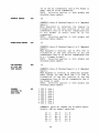
ZONE TYPES AVAILABLE FOR SELECTION
For each zone used, one of the following zone types must be selected:
1.
Entry/Exit Burglary (Delay #l). Assigned to sensors on doors through which
entry and exit will normally take place when the system is armed.
2.
Entry/Exit Burglary (Delay #2). May be set for different delay than above.
For use with sensors on overhead garage doors, etc., where longer delay is
needed to reach the keypad in the main portion of the house or building,
and more delay is needed to =it the premises.
3.
Perimeter Burglary. Normally assigned to all sensors on exterior doors and
windows requiring instant alarm.
4.
Delayed alarm only if the Entry/Exit zone is faulted
Interior, Follower.
first; otherwise, produces an instant alarm. Assigned to zone covering an
area such as a foyer or lobby through which one must pass upon entry to
Designed
to provide instant
reach the keypad to disarm the system.
intrusion alarm in the event an intruder hides on the premises prior to the
system being armed or gains access to the premises through an unprotected
area.
5
5.
Trouble by Day/Alarm by night. Can be assigned to a zone which contains a
foil-protected door or window (such as in a store), or to a zone covering a
‘sensitive” area such as a stock rocn, drug supply roan, etc., or other
controlled access area where immediate notification of an entry is desired.
During the disarmed state (day), the system will provide latched Console
annunciation (and central station report, if desired)
of openings
or
troubles (such as sensor malfunctions or foil breaks).
During the armed
state (night), violations will initiate an alarm.
6.
24-hour Silent Alarm. This type generally assigned to a zone containing an
Emergency button that is designed to initiate an alarm report to the
Central Station, but which produces no local displays or alarm sounds.
7.
24-hour Audible Alarm. This type also assigned to a zone containing an
~ergency button, but which will initiate an audible alarm in addition to
an alarm report to the Central Station.
8.
24-hour Auxiliary Alarm (Console sounder only). This type assigned to a
zone containing a button for use in personal emergencies, or to a zone
containing monitoring devices such as water sensors, temperature sensors,
etc. Designed to initiate an alarm report to the Central Station and only
provides Console alarm sounds and alarm displays.
9.
Supervised Fire (alarm on short/trouble on open).
10.
Interior that always has Entry/Exit
suppressed in the-INSTANT mode).
interior zone containing a PIR that
must pass to reach the Console for
first entering).
Ideal for an area
which the only Console is located.
Delay #1 (except that Entry Delay is
This-type typically assigned to an
covers an area through which the user
disarming purposes (whether inside or
such as an apartment entrance foyer in
FONCl?IONAL DESCRIPTION OF ZONE TYPES
The following is a description of the various zone types available which must be
selected for each physical zone. You may wish to use Table A at the end of this
description to record your selections.
Type 1.
This zone type is not enabled after
BURGLARY ENTRY/EZIT (DELAY #l):
arming until termination of the programmed Exit Delay #1. Upon entry,
the Console will emit 3 short beeps as a warning that the system must
be disarmed.
If the security code + OFF is not entered before
termination
of the programmed
Entry Delay Ill, an alarm will be
initiated at the built-in sounder, and an external alarm and latched
LCD display will be present.
A system-wide programmed nunber of
alarm reports for this zone will be allowed to be transmitted (swinger
suppression) in one armed period. Restoral.swill be sent when the zone
is restored for a time greater than its physical response time (less
than 1 second).
During the disarmed state, a faulted zone will result in a “DISARMED—
Press * to show faults” display (5137) or a NOT READY display (4137).
Subsequent depression of the * key will cause all the descriptors
and/or numbers of the faulted zones to be sequentially displayed. No
communicator reports will be initiated.
me
2.
This zone type is not enabled after
BURGLARY ENTRY/EZIT (DELAY #2):
arming until termination of the programmed Exit Delay #2. Upon entry,
the console will simply emit 3 short beeps as a warning that the
If the security code + OFF is not entered
system must be disarmed.
before termination of the programmed Entry Delay #2, an alarm will be
initiated at the built-in sounder, and an =tern~
aJ-arm and latched
6
A system-wide
LCD display.
this zone will be allowed to
one armed interval. Restorals
for a time greater than its
second) .
programmed number of alarm reports for
be transmitted (swinger suppression) in
will be sent when the zone is restored
physical response time (less than 1
“ During the disarmed state, a faulted zone will result in a “DISARMED—
Press * to show faults” display (5137) or a NOT READY display (4137).
Subsequent depression of the * key will cause all the descriptors
andlor numbers of the faulted zones to te sequentially displayed. No
communicator reports will be initiated.
&pe
3.
BURGLARY PERIMETER:
While the System is armed, a faulted zone will
initiate an alarm at the console, and an external alarm and a latched
LCD display will be present; in addition, a programmed canmunicator
report will be transmitted. Depression of any key will silence the
Console’s local alarm sounder for 10 seconds. A system-wide programmed
number of alarm reports
for this zone will be allowed
to be
transmitted (swinger suppression) by the canmunicator in one armed
period. The communicator will transmit a restord
message when the
zone is restored for a time greater than its physical response time
(less than 1 second).
During the disarmed state, a faulted zone will result in a “DlSARMEDPress * to show faults” display (5137) or a NOT READY display (4137).
Subsequent depression of the * key will cause all the descriptors
and/or numbers of the faulted zones to be sequentially displayed. No
communicator reports will be initiated.
Type 4. BURGLARY INTERIOR, FOLL(MER:
This zone will always have Exit Delay
by a fault in an
#1. The zone has an Entry Delay if preceded
Entry/Exit zone (type #1 or #2).
If not preceded by an Entry/Exit
zone fault, an immediate audible local (console) and external alarm,
latched display, and a programmed caumunicator report are initiated.
Depressing any key at the Console will silence the Console sounder for
A system-wide programmed number of alarm reports for
10 seconds.
this zone will be allowed to be transmitted (swinger suppression) by
the canmunicator in one armed period. The canmunicator will transmit a
restoral message when the zone is restored for a time greater than its
physical response time (less than 1 second).
During the disarmed state, a faulted zone will result in a “DISARMED—
Press * to show faults” display (5137) or a NOT READY (display (4137).
Subsequent depression of the * key will cause all the descriptors
and/or numbers of the faulted zones to be sequentially displayed. NO
communicator reports will be initiated.
Type 5.
BURGLARY PERIMETER, TROUBLE BY DAY/ALARM BY NIGNT: During the disarmed
state (day), faulting the zone will initiate a “troublertdisplay and a
latched sounder (beeping). The console will beep rapidly along with a
latched display of the faulted zone and the word CHECK. Pressing any
key will silence the beeping for 10 seconds. Keying the security code
+ OFF will silence the beeping, but will not clear the display of any
faulted zone until the fault condition is remwed.
Each trouble can restilt in a ‘~troublerlreport (if programmed).
A
trouble restoral message will be sent as each zone is restored to
normal condition. The maximum nunber of trouble reports per armed
period will be limited by the system-wide programmed number of alarm
reports option (swinger suppression).
7
During the armed state (night), the internal (console) and external
(if used) alarm sounders will activate and the communicator will
report alarms. A system-wide programmed number of alarm reports for
this zone will be allowed to be transmitted in one armed period.
Restorals will be sent when the zone is restored for a time greater
than its physical response time (less than 1 second).
Type 6.
24–HOtJR SILENT ZONE:
Sensors assigned to this zone, when faulted,
will initiate a caumunicator report. There will be no local displays
or alarm sounds. Upon keying the security code plus OFF, there will be
a memory indication of the faulted zone.
A system-wide programmed nunber of alarm reports for this zone will be
allowed to be transmitted (swinger suppression) by the communicator
until an OFF sequence is performed (security code plus OFF). The
caumunicator will transmit a restoral message
when the zone is
restored for a time greater than its physical response time (less than
1 second).
During the disarmed state, a faulted zone will result in a ‘~
DISARMED—
Press * to show faults” display (5137) or a NOT READY display (4137).
If an “off” sequence is performed (Code + OFF), followed by depression
of the * key, all the descriptors and/or numbers of the faulted zones
will be sequentially displayed.
Faulting a zone of this type will initiate a
24-HOUR AUDIBLE ZONE:
loud audible alarm externally and at the console, an LCD display, and
Pressing any key will silence the
a programmed canmunicator report.
Keying the security code plus OFF
Console sounder for 10 seconds.
A system-wide programmed number
will permanently silence the alarm.
of alarm reports for this zone will be allowed to be transmitted
(swinger suppression) by the canrnunicator until an OFF sequence is
performed . The communicator will transmit a restoral message when the
zone is restored for a time greater than its physical response time
(less than 1 second).
Type 8.
24-HOUR AUXILIARY ZONE: Faulting a zone of this type will initiate a
steady alarm sound at the console, an ALARM display, and a programmed
communicator report. Pressing any key will silence the Console sounder
Keying the security code plus OFF will permanently
for 10 seconds.
A system-wide programmed number of alarm reports
silence the alarm.
for this zone will be allcwed to be transmitted (swinger suppression)
The
by the communicator
until an OFF sequence
is performed.
canmunicator will transmit a restoral message when the zone is
restored for a time greater than its physical response time (less than
1 second).
Type 9.
FIRE ZONE: Opens in this zone will result in ‘troubles”. Shorts will
result in alarms. Note:
Zone 1 will support 2-wire Smoke Detectors
(using the EOL resistor configuration); Zones 2 through 8 (and 10
through 17, if used) can be used for heat detectors and pull &ations
and for 4–wire Smoke Detectors with external (manual) power interrupt;
Zone 9 cannot be used for Fire.
A fire zone in trouble will not
Fire zones may not be bypassed.
prevent the burglary system frcm being armed in any mode.
A system-wide programmed number of alarm reports for this zone will be
allowed to be transmitted (swinger suppression) by the canmunicator in
8
one armed period. The communicator will transmit a restoral message
when the zone is restored (less than 1 second).
Type 10.
INTERIOR DELAY ZONE:
This type of zone will always have Entry
Delay #1 and Exit Delay #1.
This zone is not enabled after arming
until termination of the programmed Exit Delay #1. If this zone is
faulted, three beeps will be emitted by the Console. If the security
code + OFF is not entered before termination of the programmed Entry
Delay #1, an alarm will be initiated. A system-wide programmed nwnber
of alarm reports for this zone will be allowed to be transmitted
(swinger suppression) by the ccinmunicator in one armed period. The
communicator
will transmit a restoral message when the zone is
restored for a time greater than its physical response time (less than
1 second).
During the disarmed state, a faulted zone will result in a “DISARMED—
Press * to show faults” display (5137) or aNOT READY display (4137).
Subsequent depression of the * key will cause all the descriptors
and/or numbers of the faulted zones to be sequentially displayed. No
communicator reports will be initiated.
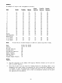
TABLE A. ZONE ASSIGNMENTS
A zone type must be assigned to each physical zone in use. For convenience, the
following chart has been prwided for checking off selections made.
I
ZONE TYPE
I
PHYSICAL ZONES
1
2
3
4
5
6
7
8
1. ENTRY/EXIT, Delay #1
(Burglary)
2. ENTRY/EXIT, Delay #2
(Burglary)
3. PERIMETER (Burglary)
4. INTERIOR, FOLLOWER
(Burglary)
5. TROUBLE BY DAY/ALARM
BY NIGHT (Burgtity)
6. 24-HOUR SILENT
I
[
7. 24-HOUR AUDIBLE
8. 24-HOUR AUXILIARY
9. FIRE ZONE*
10. INTERIOR, DELAY
(Burglary)
v
I
* Physical Zone 9 cannot be used for Fire.
** Available when 4152LM and 4208 Zone Expander used.
9
**
1,
ZONE EXPANSION
Zone expansion to an additional 8 zones is achieved by connection to No. 4208
Eight-Zone Expander by a single pair of wires providing
both power and
signaling.
Each of the 8 zones on the No. 4208 can be programmed from the
various types described in this manual that are available for use on the basic 9
zones, with one exception.
There is no ability to support 2 wire smoke
detectors on any of the zones available in the No. 4208 Zone Expander. The No.
4208 Zone Expander may be located near the No. 4140 or remotd.y from it. The
two wire run to it should utilize twisted pair wiring and should not be run in
close proximity to protected praises interccm wiring [at least a 3-inch (8 cm)
For the maximum wiring run permissible to the zone expander for
separation] .
various’ wiring gauges, see the Specifications Section relative to the No. 4208
Zone Expander later in this manual.
In order to utilize the No. 4208 to obtain zones 10-17, this
product’s DIP switches must be set as follows:
IMPORTANT :
0000
(as if set for sensor nunbers 113-120, as
cited in the instructions for the No. 4208)
Installation
instructions
for the wiring connections to the No.
provided in a subsequent section entitled “WIRING TO No. 4208”.
4208 are
4-DIGIT SECURITY CODES
Installer Code:
The instsller programs the Installer Code initially as part of the programming
‘he Security Control”).
In this system, the
procedure (see mprogrming
installer is considered to be user #1. The installer code permits re-entry into
used to exit the
the programming
mode (unless *98 has been previously
programming mode) and also allows access to the normal functions of the systen.
During initial programming, the installer also programs the Master security code
into the system. Open/Close reporting must be enabled for User # 1 for this code
to be operational.
[1[1[1[1
Installer Code (User #l), assigned during programming.
Installer exits programming mode with:
W39
(allows re-entry into programming mode with installer code).
*8
(does not allow re-entry to programming mode unless system is
Installer
code is
first powered down and then repowered).
disabled when this exit is used.
or
Master Security Code:
The Master security code can be used to assign up to thirteen secondary codes
(to users #3-#15): it can also be used to remove all secondary codes from the
The person to whom the Master code is assigned is
system
(individually).
In some applications (canmercial installations, for
considered to be user #2.
example), user #2 (with Master code) will be the main user of the systen (see
In other applications (such as in an
Application 1 on a following page).
apartment complex, for example), user #2 (with Master code) may not be the
actual end user of the system (see Application 2 on a f~lowing Page).
10
Secondary security codes are assigned by user #2 (with Master Code) as follows:
Master Code + CODE key + User # (03-15) + Secondary Code
The system will emit a single beep when each secondary code has been successfully entered.
Note:
When a secondary code is inadvertently repeated for different users,
or one user’s code is another’s duress code, the lower user number
will take priority.
Individual secondary security codes can be deleted by user #2 (with Master Code)
as follows:
Master Code + CODE key + User # (03–15)”+ Master Code
Note:
All security codes, master and secondary, permit access to the system
for arming, disarming, etc.
Secondary (Temporary) Security
Codes:
As stated prwiously, up to thirteen secondary codes can be assigned – to users
The configuration in Application 1 shows that secondary (or
3 through 15.
temporary) codes may be assigned by the primary user (user #2) to as many as
thirteen employees, each with a unique code. Note that user #3 can also assign
secondary codes to users 4-14 if required, but in the typical arrangement shown
If so, the
in Application 1, there may never be a practical need for this.
primary user (#2) can elect to omit user #3 when assigning secondary codes.
In the configuration shown in Application 2, user #3, who is the primary user,
may need to assign secondary (temporary) codes to maids, cleaning persons, etc.
Since the system allows user #3 to assign secondary or temporary codes to as
many as elwen users (4-14), this need can be met.
User #3 cannot assign (or
delete) user #15’s code, which is strictly under the control of user #2, who may
be the building manager or cwner in the configuration shown in Application 2.
See Table B, which illustrates the various levels of authority that exist for
security codes.
User #3 can assign secondary (temporary) codes for users 4-I4 as follows:
User #3 Code + CODE key + User # (04-14) + Secondary Code
User #3 can delete secondary codes assigned to users 4–14 as follows:
User #3 code + CODE key + User # (04-14) + User #3 Code
TAELE B. LEVELS OF AUTHORITY FOR SECURITY CODES
User
No.
Can assign or delete
Secondary Code of User:
NONE
#1 (Installer)
#2
#3 through #15
#3
#4 through #14
#4-
NONE
#15
11
APPLICATION
1
?
MASTER SECURITY CODE
MAIN USER
“Ooucl
1
CAN ASSIGN TEMPORAW
user,,
CODES TO: 1
+
EMPLOYEE, CLEANING PERSON, ETC.
(&XXS
Jlnclcl”ser#3*
3 thru 15)
--JKKxl”ser,,
--Elucln”sem
Note: All codes can Arm/Disarm
the System
*UnUDUser#6
●User #3 can assign secondary codes to users 4-142
1 A seconda~
(temporary) code is
ZiSSig@
‘OUnDUser#7
asfOllOWS
User #2 (Master) Code+ CODE key+ User # (03-1 5)+ Temporary
Code
2 User #3 can assign temporary codes as follows
~UUUU.ser#8
~UDUU
User#9
User #3 Code + CODE key+ User # (04-14) + Temporary Code
~UUODUser#10
~UOUu
~UUUD.ser#12
‘ODUUUser#13
~UOUUUser#14
‘UUUu.ser#15
12
User#ll
APPLICATION
2
MASTER SECURITY
BUILDINGMANAGER, ETC.
CODE
(User #2)
*DUUU
User#2*
CAN ASSIGN SECONDARY CODES TO 1
SECONDARY
SECURIW CODE
❑
clclcl
User #15
-l+i
P+-lllfFTii’Ei
User #3
CAN ASSIGN TEMPORARY
TEMPORARY
SECURITY CODES
CODES TO 2
+
MAID,CLEANING PERSON, ETC.
-tKK3D
User #4
(User #4 - #14)
Note: AH codes can Arm/Disarm
the System
●This code, although actually a secondary code, will serve as a master
security code for the apartment owner, etc. since user #3 is the primary
user of the system in this application.
‘ A secondary code is assigned as follows:
Jxlun
User #5
-Clulxl
User #6
~lznnn
User #7
-Cluan
User #8
~nnlxl
User #9
-Uncln
User #10
-Cllxlcl
User #11
-noon
User #12
-Ixxln
User #13
Master Code + CODE key+ User # (03-1 5)+ Secondary Code
2 A temporary code is assigned as follows:
User #3 Code + CODE key+ User # (04-1 4)+ Temporary Code
-+Dclml
13
User #14
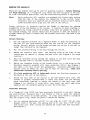
WIRING CONNECTIONS
(See Diagram 1, Summary of Connections)
Terminal blocks with screw terminals are provided to interface the 4140 to the
wired loops, external sirens and/or motor bell, the back-up battery, to externally powered devices (auxiliary current), and to the plug-in DC Power Pack.
Grounding the System
A proper earth ground must be provided for the systen in order to protect the
system from lightning and electrostatic discharge damage.
TB2-3 is the earth
ground connection point.
Connect a lead from this terminal to a suitable earth
ground (a metallic cold water pipe or electrical box may be used in some
locations).
m
Terminals
1:
Zone l(+) –
2:
Zone l(-) – When Zone 1 is used as a fire zone, a 13,000 Ohm EOLR
should be used and the high side of the zone will be found on TB2-4
In this application, Terminal 1
(if programmed for fire usage).
would not be used.
3:
Zone 2(+). *
4:
Zones 2 and 3 Return.
5:
Zone 3(+).*
6:
Zone 4(+).*
7:
Zones 4 and 5 Return.
8:
Zone 5(+).*
9:
Console Data Out (YELLOW).
10:
N.C. Zone, Normal Response (350 Msec).
Console Data In (GREEN).
* Zone that is programmable for use as a N.C. sensor loop or as end-ofline resistor supervised N.O./N.C. sensor loop.
m
Terminals
1:
DC (+) Input from No. 1350 plug-in pcwer pack (18VDC, 700 mA)
2:
DC (–) Input from No. 1350 plug-in power pack.
3:
Earth Ground.
4:
Zone 1 (+) when zone is used as an End–of-Line Resistor supervised
2-wire smoke detector compatible fire zone.
5:
Battery (+) - When AC is present, 13.8 VDC is being developgd to
recharge No. 486 (YUASA NP412) battery and when AC is absent, 12 VDC
Battery lead reversal damage is
current is drawn from the battery.
protected against by fuse F2. Used to provide alarm relay coil power
and alarm sounder pwer.
6:
Battery (-)/ Remote Console Ground (BLACK).
14
7:
8:
9:
10:
11:
12:
13:
14:
Continuous Auxiliary/Remote Console Power (R~):
max.
Alarm relay activation signal.
Zone 6(+)=*
Zones 6 and 7 Return.
Zone 7(+).*
Zone 8(+).*
Zones 8 and 9 Return/Auxiliary Power (-).
Zone 9(+) - N.C. Zone, Fast Response (15 Msec).
+12 VDC at 400 mA
* Zone that is programmable for use as a N.C. sensor loop or as end-ofline resistor supervised N.O./N.C. sensor loop.
Alarm Relay Board Connections:
Usage
Terminal
1
12V (+) (must be wired to TB2-5 on Control).
2
12V (-) (must be wired to TB2-6 on Control).
3
Siren (-)
4
Siren (+)
5
Not used.
6
Not used.
7
Trigger (must be wired to TB2-8 on Control).
‘Digital Communication Interface Board Connections** (Phone Line Interface):
Terminals
1:
Ground Start Output (to BLUE LEAD on No. 675 Ground Start Module).
2:
Incaning Phone Line (TIP).
3:
Incoming Phone Line (RING).
4:
Handset (RING).
5:
Handset (TIP).
Warning:
**
To prevent the risk of shock, disconnect telephone line at Telco
jack before servicing the unit.
The Digital Communication Interface board (4171XT) must be mounted onto the
main circuit board by the installer
(see the separate
Supplementary
Installation Instructions that hav”e been provided).
15
+
1
(dOO1
!3 N ‘3 SN0dS3H
1SV3)
6 ilNOZ
I
,1
1
—- —-- ~
-----;
I
I
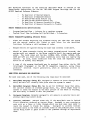
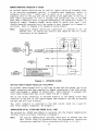
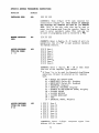
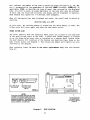
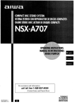
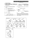
REMOTE KEYSWITCH OPERATION & WIRING
An optional Remote” Keyswitch may be used for remote arming and disarming (this
momentary
switch is
is an installer-programmed
option) . A normally–open
connected across Zone 7 (which must be given up as a protection zone).
A
momentary short of the zone will arm the System in the AWAY mode; if the key is
held (short maintained) for over 3 seconds, the System will arm in the STAY
mode. When a momentary short is applied subsequently, the System will disarm. A
keyswitch
tamper (normally-closed) switch wired in series with zone 7 will
disable keyswitch operation until the system is next disarmed via a keypad, if
activated. Refer to Diagram 2 for KeysWitch wiring details.
Note:
whether End-of–Line supervision is selected or not (in
Regardless
Address *41), an end-of–line resistor must still be used for proper
functioning of the keyswitch.
r ----t
I
REMOTE
____
7
I
I
lREADYI
RED
GREEN
#11~
I
KEYPAO
I
I
I
CONNECTOR
CONNECTS TO
REMOTE KEYPAD
INTERFAcE ON 4140
(SEE DIAG. 1)
----(AHMED}
RED
BLUE
GREEN
TO FLYING
LEAOS
ON 10. PIN REMOTE
KEYPAO
CONNECTOR
Q
BLIJE
[
REO
GREEN
(PIN
31
IPIN
6)
IPIN
6)
I
I
I
I
I
I
TAMPER
E
SWITCH
WAC I
i
I
I
I
I
I
1.
/
I
TOTS2-11
-
[
I
TO414O
TERMINAL BLOCK
TB2
TO TB2-10
I
-
I
J
SUGGESTED
PARTS
No, 9787 lVPE
SLIM @XN3LE LEO PLATE
No. 112 N,C, TM4PER
No. 4073.70 IS NOT A
U.L USTEO ITEM.
(N O )
!
1
NOTE:
LOCK
SWITCH
FoR
REMOTE
I
KEYSWITCH
1
EOLR
SW77CH
I
No. 4073.70 HIGN SECURllY KEYIOCK, SPRING LOADED IN.O.I
N3707.1O 1O-PIN MALE.TC-MAI.E
AOAPTER [LEO lNTERFiCE)
‘
i
6A4131-10
IWPIN
CONNECTCR
W77N 1.E#Lk3
Diagram 2.
I
i
I
1
‘--------------J
KEYSWITCH WIRING
Optional Remote Keypad Connection (4131/4147)
An optional remote keypad (4131 or 4147) may be used with the System. Two 10-pin
female connectors have been supplied for keypad interfacing to the 4140 control
board (see Diagram 1, Summary of Connections) . Each connector is equipped with
color-coded flying leads that are 12 inches (30 cm) in length.
One of the 10-pin connectors is attached directly to the mating 10-pin male
connector on the 4131 or 4147 remote keypad (the connector can only be inserted
one way, and will lock in place) .
The other connector is connected to the 4140 control board via
male 10–pin adapter (supplied). See Diagram 1.
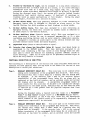
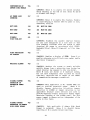
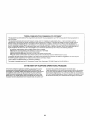
INSTALLATION OF No. 4152LM AND WIRING TO
l?o.
a male-to-
4208
The optional No. 4152LM Loop Module is instailed onto the Digital Canmunication
Interface board as follows, referring to Diagram 3.
Note:
The Digital Caomunication Interface board must be mounted onto the
main circuit board (in accordance with the Supplementary Installation
Instructions supplied) before proceeding with steps a, b, and c.
17
a.
Note the 8 square-shaped connector pins on the Communication Interface
board. Position the 4152LM board over that board so that these pins engage
the mating sockets (header) on the underside of the 4152LM.
Press the
4152LM down until the pins are fully seated.
b.
Secure the No. 4152LM by means of 3 screws (supplied).
c.
Connect two wires from the loop terminals (1 and 2) on the 4152LM to
For
terminals 11 and 12 (respectively) on the 4208 Zone Expander.
information on wire usage, etc, refer to a previous section entitled “ZONE
EXPANSION”.
(d
BOARD
CONNECTOR
PINS
Diagram 3:
No. 4152LM INSTALLATION AND WIRING TO No. 4208
CONSOLE WIRING CONNECTIONS (5137 or 4137)
5137 or 4137 Consoles used with the system are connected to the terminals on the
Control as indicated in Table C, which shows console wire colors and their
assignments. The auxiliary current capability of the system can be expanded, if
desired, by not using the Console Power input to power consoles except when AC
pwer is absent. The latter allows the entire auxiliary current to be used for
motion detectors and other auxiliary devices, as well as allowing more consoles
to be used. This expansion is accomplished by using a separate No. 1350 Power
pack to provide unregulated power to the consoles via the connections shown
below (see Diagram 1 also). One No. 1350 can pwer up to 6 consoles.
TABLE C.
4140
Control Terminals
5137/4137
Leads
RED
YELLOW
GREEN
BLRCK
to
to
to
to
BLUE
to
TB2–7 (CONSOLE POWER)
TB1-9 (DATA OUT)
TB1-10 (DATA IN)
TB2-6
(CONSOLE GROuND) - connect ~so
to (-)
output of separate No. 135o powkr Pack (if used).
(+) output of Separate No. 1350 Power Pack (if
used).
18
MOUNTING THE CONSOLE(S)
There are two methods that may be used for mounting consoles – Surface Mounting
and Flush Mounting. If a “rough-in” ring (4133) has been installed in the wall
in a new construction application, only the flush mounting method is applicable.
Note:
Early production 4137 consoles are equipped with flying leads exiting
from the rear of the console for connection to the control. Later
production units are supplied with an interface connector (with flying
leads attached) which plugs into the rear of the console.
Proper selection
of mounting location and height is important for optimum
viewability of the LCD display on the console. A location in which lighting is
directly above the console should be avoided, since this can shadow the display.
For optimum viewing, the console should also be mounted so that the display is
slightly below eye level to ensure that the system’s users will look down at the
display.
Surface Mounting:
1.
Use the template provided (on a separate sheet) to mark the positions on
the wall for the screw mounting holes and the cut–out for the interface
wiring. Use wall anchors for the screws and make the cut–out in the wall no
larger than indicated on the template.
2.
Pull the interface wiring in the wall through the cut-out.
3.
Remove the console’s back cover. The securing screw at the front of the
console must be removed to release the back cover (see Diagram 4 for screw
location).
4.
Pass the interface wiring through the opening in the back cover and then
mount the back cover to the wall surface with screws.
5.
Splice the interface wiring to the console wires (or to the wires on the
interface connector supplied with later production 4137s). See Diagram 1
and Table C for wire colors and assignments.
Insulated solderless wire
splices (such as Ademco No. 311) may be used for splicing.
Check wire
connections carefully before splicing.
6.
If a late production 4137 is being used, attach the interface connector to
the board at the rear of the console.
7.
Attach the main body of the console to the wall-mounted back cover. The
console is properly attached when it snaps into place. Use the securing
screw (previously removed) to secure the console to the back cover (see
Diagram 4 for location of screw hole), then insert the small name plate
supplied into the recessed opening to cover the screw head.
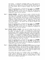
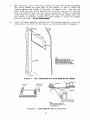
Flush Wall Mounting:
If a “rough-in” ring (4133) has been previously installed in the wall (during
new construction), disregard step 1 and proceed to step 2, since the required
opening for the console is already present. If a wall plate (4136) is installed
over the rough–in ring, remove the plate to expose the opening.
1.
Cut an opening measuring 4–5/16” (11 cm) high by 7–3/4” (20 cm) wide
between studs in the wall. The opening must be no less than 1-1/2” (4 cm)
from either stud. Avoid cutting the opening any larger than that specified.
See Diagram 5.
19
Note:
A special “trim ring t?has been supplied for installation between
the wall and the console for those cases where the opening has
inadvertently been made too large (over-cutting).
The console
fits into the recess in the trim ring which will extend 1/2” (1.3
cm) beyond the console front panel, and thus cover any opening
that might otherwise be visible as a result of over-cutting.
2.
Remove the back cover on the console. The securing screw at the front of
the console must be removed to release the back cover (see Diagram 4 for
screw location). Discard the back cover, but retain the screw.
3.
Pull the interface wiring in the wall through the opening prwiously made.
Splice the appropriate wires to the console wires (or to the wires on the
interface connector supplied with later production 4137s).
See Diagram 1
and Table C for wire colors and assignments. Note that the Blue wire on
the console may not necessarily be used. Insulated solderless wire splices
(such as Ademco No. 311) may be used for splicing. Check all wire
connections carefully before splicing.
4.
If a late production 4137 is being used, attach the interface connector to
the board at the rear of the console.
INSERT NAMEPLATE
INTO RECESSED
AREA (COVERS SCREWI
‘7
.
)
>
\
>
\
\
/
SECURING
SCREW
Diagram 4.
INSERTING NAMEPLATE
Refer to Diagram 6 for Steps 5. 6 and 7:
5.
Mount the console as follows. Insert securing screw (previously renoved) in
screw hole at front of console (see Diagram 4) and attach metal clip (at
the rear) as shown in Diagram 6. Turn the screw until the clip enters the
cylindrical plastic guide point about 1/8 of an inch (3 mm).
6.
Insert the straight end of the flat spring into the slot at the other side
of the console, as shown.
20
7.
With the metal clip in the vertical position, mount the console by hooking
the spring behind the right edge of the opening so that it holds the
console against the inside of the wall, as shown at (A). Now turn the
screw (frcm the front of the console). The clip will turn until it hits the
clip stop and will then draw the console forward (B). Continue turning the
screw until the console is flush against the wall then, making sure that
the console is straight. tighten the screw further to secure the console
firmly in position. DO NOT OVERTIGHTEN~
8.
Insert the small nameplate supplied into the recessed opening to cover the
screw head at the front.of the console, as prwiously shown in Diagram 4.
i 1!
I
I
I
I
i
I
I
I
I
I
I
I
I
I
I
I
I
I
I
i
I
11
II
I
II
II
I
:
I I
Ill
WOTE
:
A ROUGWIN nlNG 14133) MAYBE
?F!ESENT IN NEW CONSTRUCTION
IF SO.
SIMPLY REMOVE COVER PLATE TO
EXPOSEFRAMEO
S3PENINGSLHTASLE
FOR FLuEH MOUNTING OF THE CXX4SOLE.
Ill
k
II
-STUDS
Ill
1,
‘1
II
:
11:
Ill
II
1+,
\\
\\
Diagram 5.
\\
.
.
WALL PREPARATION FOR FLUSH MOUNTINGTHE
A,
METAL CLIP
CONSOLE
SHEETROCK
SPRING INOTE
ENDI
w
B
.
IF SHEETROCK IS TOO THICK,
BREAK OFF THE SCORED WING
NoTE
:
+5/16’’(11
WALL
FLUSH
Diagram 6.
cm)H
X 7.3//(20
OPENING
cm) W
IS REQuIRED
FOR
MOUNTING.
FLUSH MOUNTING THE 5137/4137/4147
21
PROGRAMMING THE SECURITY CONTROL
Installer
options are stored in non–removable, electrically erasable. non–
volatile EEPROM memory.
These options must be programmed for the particular
installation to establish its specific alarm and reporting features.
The security control may be programmed from an optional 5137 or 4137 remote
console, or can be programmed locally from the 699 Programmer.
Information
regarding the Programmer
is included with the No. 695–30XT Programming
Cartridge.
When programming from the 5137 console, prompts for each field description (only
field number will. be displayed on the 4137 console) and field number will be
displayed on the 2–line, 32–character LCD display; also, each entry is displayed
as it is keyed in. After programming, values that have been entered in each
field can be reviewed and, if neccesssary, modified.
The system is factory–programmed to a set of preset values, which can be altered
by the installer to suit the specific needs of a particular installation or
installation company. The preset values are detailed in the Factory Programming
Table.
Note:
Programming information is stored in non–volatile 3EPROM memory in the
control
(removal of power will not result iv the 10SS of the
information). Consequently, it is possible to program the system at
any time – even at the installer’s premises prior to the actual
installation. Simply apply power temporarily ?a ‘:he control and the~
program the unit as desired.
When programming from the console, note the following:
1.
Enter the Programming mode by simultaneously depressil~; The * and # keys
within 30 seconds after pwer is applied to the Control, or subsequently k.y
keying the code 4 + 1 + 4 + O followed by depression of CODE + O + O keys.
Once an installer code is programmed, use it instead of 4140 to gain access
to the programming mode.
2.
Immediately following entry into the program mode, the following will be
displayed on a 5137:
Program Console
* Fill # View – 00
and on a 4137:
00
To program a data field, key * PIUS Address (for example, *01), then make
the required entry. To simply rwiew a data field, key # plus Address.
3.
4.
When a data field has been completely programmed, the console will “beep”
three times and then automatically proceed to, and display, the next data
field address to be programmed.
If the number of digits that you enter in the data field is less than the
then the console will
permitted
(for example, phone number),
display the last data entered. To proceed, the next data field address to
be programmed must then be entered (for example, *05).
maximum
5.
If an address is improperly entered, the console will display FC . If a
program entry is improperly entered (for example, a larger number than that
In either case,
which is permitted), the console display will go blank.
simply re–enter the number.
The following is a description of commands necessary for programming:
22
FUNCTION
PROCEDURE
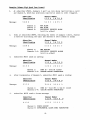
ENTER PROGRAMMING MODE:
1.
POWER UP, then depress * and # simultaneously
within 30 seconds of powering up.
OR
Initially, Key: 4+l+4+Oplus~DE
o.
2.
key+
0+
OR
After Installer Code is programmed, key: Inst&l.ler
Code + CODE key + O + O.
3.
Notes:
User #1 (installer) must be enabled
(in
Address 52) if ~pe 3 method of entry is to
be used.
Type 3 method of re-entry to the programming
mode is inhibited if the programming mode is
exited via use of =8.
Type 1 method of entry can always be used,
unless console programming has been locked
out by the remote downloader.
EXIT PROGWING
MODE:
*9
(always allows re-entry to programming mode via
Type 3 entry method above), unless
console
programming
has been locked out by the remote
downloader) .
*8
(inhibits re-entry to programming mode via Type 3
entry method).
Note:
When the programming mode is exited, a Iminute set-up period must elapse before the
system can properly function.
ADVANCE TO FIELD:
* + ADDRESS (e,go, 01, 1(J,21.,etc.),
PRCXGRAMFIELD:
* + ADDRESS, followed by data entries.
ERASE FIELDS:
* + ADDRESS + *
READ FIELD:
# + ADDRESS
RESTORE FACTORY
PROGRAM SETTINGS:
*7
(see Factory Programming Table).
EITCERZONE DESCRIPTION AND INSTALLER
MESSAGE PROGRAMMING
MODE :
*3
(only relwent
(ody
applies to Addresses 31 thru 34).
if 5137 Console is being used).
SPECIAL MESSAGES
OC = OPEN CIRCUIT (no communication between the Console and the Control).
FC = FIELD CODE ERROR (program entry mistake, re-enter the data).
23
my
~ ~
(5137) or AC and my
(4137)
After powering up, ****DIS~****
will be displayed after approximately 7 seconds. Enter the programming mode by
simultaneously depressing * and # within 30 seconds.
The System is factoryprogrammed with preset values (see Table D) that can be altered via the
programming instructions that follow the table.
FACTORY PRESET VALUES
Factory preset values serve two purposes:
.
They can reduce programming time on the part of the installer if many of
the preset values shown in the table are accepted.
.
They will permit an installer who is unfamiliar with this product to
quickly set up the systen for bench test so that familiarity with the
operation of the system can be achieved in a shorter period of time.
The factory preset values are defined in the Table that follows:
TABLE D.
Address
FACYCORYPROGRAMMING
Function
Factory Programmed Value
00
INSTALLER CODE
[41[11[41[01
01
MASTER SECURITY CODE
[11[21[31[41
02
ASSIGN RESPONSE
TYPE EOR ZONES
1-8
Z1
Z2
Z3
Z4
Z5
[01[91 Fire
[0][31 Perimeter, Burglary
[0][41 Interior, Follower, Burglary
[0][51 Trouble by Day/Alarm by Night, Burg.
[11[01 Interior, Delay, Burglary
Z6 [01[71 24-hour audible
Z7 [01[81 24–hour Aux
Z8 [01[11 Entry/Exit (Delay #l), Burglary
03
ASSIGN RESPONSE
TYPE FOR ZONES
9-16
Z9 [01[01
Zlo[o] [01
z1l[o] [01
Z12[O] [0]
Z13[O] [01
Z14[O] [01
Z15[OI [01
z16[01 [01
04
ASSIGN RESPONSE
TYPE FOR ZONE 17
Z17[O] [01
[01[01
[01[01
[01[01
[01[01
[01[01
[01[01
[01[01
24
05
ASSIGN RESPONSE
TYPE FOR VARIOUS
KEYPAD PANICS
AND ZONE
EXPANDER WIRING
SUPERVISION
1
2
3
4
5
[01[01
[01[01
[01[01
[01[01
[01[01 Short in Wiring to Zone Expander
(displays “97”)
6 [01[01
7 [01[01
8 [01[01
06
07
1 and * Panic (displays “95”)
3 and # Panic (displays “96”)
* and # Panic (displays “99”)
DESIGNATE RIGHT
ZONE USAGE
[01[01[01[01[01[01[01 Zones 10-16 (none)
DESIGNATE RIGHT
ZONE USAGE
[01 zcm 17 (none)
08
NOT USED
09
ENTRY DELAY #1
[0][2] (30 seconds)
10
EXIT DELAY #1
[0][3]
(45 seconds)
11
ENTRY DELAY #2
[01[61
(90 seconds)
12
EXIT DELAY #2
[01[81
(120 seconds)
13
ALARM SOUNDER DUWTION
[0][41
(8 minutes)
14
ALARM SOUNDER SELECTION
[01
(Alarm Relay compatibility)
15
KEYSWITCH ARM/DISARM
ENABLE
[01 (Disable)
~NFIRMATION
ARM ING DING
[01 (Disable)
16
OF
17
AC POWER LOSS SOUNDING
[01 (Disable)
18
NOT USED
[01
19
NOT USED
[01
20
NOT USED
[01
21
DI SABLE FIRE TIME-OUT
[01 (No)
22
FIRE INDI CATION ON
DISPLAY
[11 (Enable)
23
MULTI PLE ALARMS
[11
(Yes)
24
TAMPER DETECTION
DISABLE (ZONES 10-17)
[01
(Enable)
DURESS REPORT DISABLE
(ADEMCO HIGH SPEED)
[01 (Enable)
NOT USED
[01
25
26
25
27
TEST REPORT INTERVAL
[2]
(24 hours)
28
POWER UP IN PREVIOUS
STATE
[1]
(YES)
29
QUICK ARM
[1]
(Enabled)
30
TCUCH-TONE OR ROTARY
DIAL
[11
(Touch–Tone)
31
PABX ACCESS ~DE
No Entry
32
SUBSCRIBER ACCT.No.
No Entry
33
PRIMARY PHONE NO.
No Entry
34
SECONDARY PHONE
No Entry
35
CS DOWNLOAD PHONE No.
No Entry
36
CS ID No.
[11[51 [11[51 [11[51 [11[51 [11[51 [11[51
[11[51 [11[51
37
DOWNLOAD CCMMAND
ENABLES
NO.
38
INHIBIT BYPASS OF ZONE
39
OPEN/CLOSE REPORTING
ENABLE BY USER CODE
1 [1]
2 [1]
3 [0]
4 [1]
5 [11
6 [1]
7 [1]
8 [11
Dialer Shutdown enabled
System Shutdown enabled
Not Used
Remote Bypass enabled
Remote Disarm enabled
Remote Arm enabled
Upload Program enabled
Dcwnload Program enabled
[01[01
(All non-fire zones bypassable)
[01[01[01[01[01[01[01
(disabled for Users 9-15)
REPROGRAM/DOWNLOAD
ATTEMPT REPORT
[01[01
(No code reported)
EOLR DISABLE
(Zones 2-8)
[11
(End-of-Line Resistor
not required)
42
DIAL TONE PAUSE
[01
(5 seconds)
43
DIAL TONE DETECTION
[11
(Dial Tone Detection Enabled)
44
RING DETECTION COUNT
[01[01
(Ring detection disabled)
45
PRIMARY ACK WAIT
[01
(30 seconds)
46
PRIMARY TRANSMISSION
FORMAT
[01
(Ademco Low Speed)
40
41
26
supervision
47
48
SECONDARY ACK WAIT
SECONDARY TRANSMISSION
FORMAT
[01
(30 seconds)
[01
(Ademco Low Speed)
SINGLE MESSAGE
TRANSMISSION WITH
CHECKSUM VERIFICATION
[01
(No)
SESCOA/RADIONICS
SELECTION
[01 Radionics with 0-9, B-F reporting.
51
DUAL REPORTING
[0]
52
OPEN/CLOSE REPORTING
ENABLE BY USER CODE
49
50
(No)
[11[01[01[01[01[01[01[01
(disabled for Users 2-8)
53
4+2 ZONE EXPANDED
FORMAT SELECTION
[01 (Not selected)
54
4+2 ZONE FORMAT
SELECTION
[01 (Not selected)
55
ALARM REPORT
[01 (Standard report)
56
RESTORE REPORT
[1]
(Expanded)
57
BYPASS REPORT
[01
(Standard report)
58
TROUBLE REPORT
[01 (Standard report)
59
OPEN/CLOSE REPORT
[01
(Standard report)
60
LOW BATTERY, AC LOSS
AND TEST REPORT
[01
(Standard report)
61
62
CHANNEL ASSIGNED
TO EACH ZONE
CHANNEL ASSIGNED TO
EACH ZONE (CONT’D)
1
2
3
4
5
6
7
8
[0][01 Zeroes for zones 1 - 8 (no code
reported)
[01[01
[01[01
[01[01
[01[01
[01[01
[01[01
[01[01
1
2
3
4
5
6
7
8
[01[01
[01[01
[01[01
[01[01
[01[01
[01[01
[01[01
[01[0]
27
Zeroes for zones 9-16 (no code
reported)
63
64
65
CHANNEL ASSIGNED TO
EACH ZONE (CONT’D)
CHANNELS ASSIGNED
TO DURESS AND
VARIOUS KEYPAD
PANICS
[01[01
[01[01
[01[01
[01[01
[01[01
[01[01
[01[01
[01[01
Zero for zone 17 (no code
reported)
All zeroes in 8 locations (same as
Address *61)
1 [01[01
2 [01[01
3 [01[01
4 [01[0] Duress
5 [01[01 Short on Wiring to Zone Expander
(displays 97)
1
& * Panic (displays 95)
6 [01[01
3
& # Panic (displays 96)
7 [01[01
*
&
# Panic (displays 99)
8 [01[01
ALARM REPORTING
CODES ASSIGNED
TO EACH CHANNEL
66
1
2
3
4
5
6
7
8
ALARM REPORTING
CODES ASSIGNED TO
EACH CHANNEL
(~NT’D)
1 [01[01
Zeroes for channels 1-8 (no code
reported)
2
3
4
5
6
7
8
[01[01
[01[01
[01[01
[01[01
[01[01
[01[01
[01[01
9
10
11
12
13
14
15
[01[01
[01[01
[01[01
[0][01
[01[0]
[01[01
[01[01
Zeroes for channels 9-15 (no code
reported)
[01[01
Not Used
67
NON–ALARM CODES
[01[01
All zeroes
(no code reported)
68
NON–ALARM CODES
(CONT’D)
[01[01
All zeroes
(no code reported)
ZONE TYPES 1-4
RESTORE REPORT
ENABLE
[11[11[11[11
Enabled (all)
ZONE TYPES 5-8
RESTORE REPORT
EIWBLE
[11[01[01[01
Zone Type
5 enabled,
others disabled
69
70
28
al 1
71
72
73
74
75
76
ZONE TYPES 9 & 10
RE STORE REPORT
ENABLE
Enabled (all)
[11[11
4+2 EXPANDED FORMAT
ZONES 1–8 EVENT
DIGIT (lst
digit)
1
2
3
4
5
6
[0][0]
[0][0]
[0][0]
[0][0]
[0][0]
[0][0]
AL
TR
BY
AL RE
TR RE
BY RE
4+2 EXPANDED FORMAT
ZONE S 9-16 EVENT
DIGIT (lst digit)
1
2
3
4
5
6
[0][0]
[0][0]
[0][0]
[0][0]
[0][0]
[0][0]
AL
TR
BY
AL RE
TR RE
BY RE
1
2
3
4
5
6
[01[01
[0][0]
[0][0]
[0][0]
[0][0]
[0][0]
AL
TR
BY
AL RE
TR RE
BY RE
4+2 EXPANDED FORMAT
KEYPAD
PANICS/ZONE
EXPANDER WIRING
SUPERVISORY EVENT
DIGIT
1
2
3
4
5
6
[01[01
[0][0]
[0][0]
[0][0]
[0][0]
4+2 EXPANDED FORMAT
ZONES 1-8 ID DIGIT
(2nd digit)
1 [01[01
4+2 EXPANDED FORMAT
ZONE 17 EVENT
DIGIT (lst digit)
2
3
4
5
AL
TR
BY
AL RE
TR RE
[01[01 BY RE
[01[01
[01[01
[01[01
Zeroes for zones 1–8 (no
codes reported)
Zeroes for zones 9–16 (no
codes reported)
Zeroes for zone 17 (no
codes reported)
Zeroes for keypad
panics and for zone expander
wiring supervisory (no
codes reported)
Zeroes for zones 1–8 (no
codes reported)
[01[01
6 [01[01
7 [01[01
8 [01[01
77
78
4+2 EXPANDED IORMAT
ZONES 9-16 ID DIGIT
(2nd digit)
9
10
11
12
13
14
15
16
4+2 EXPANDED I13RMAT
ZONE 17 ID DIGIT
(2nd digit)
17 [01[01
[01[01
[01[01
[01[01
[01[01
[01[01
[01[01
[01[01
[01[01
[01[01
[01[01
[01[01
[01[01
[01[01
[01[01
[01[01
29
Zeroes for zones 9–16 (no
codes reported)
Zeroes for zone 17
(no codes reported)
79
4+2 EXPANDED FORMAT
KEYPAD PANICS /ZONE
ZONE EXPANDER WIRING
SUPERVISORY ID DIGIT
(2nd digit)
[01[01
[01[01
[01[01
[01[01
[0] [0]
[01[01
[01[01
[01[01
Duress
Short in Wiring to Zone Expander
~ & * panic
3 & # Panic
* & # Panic
80
4+2 EXPANDED FORMAT
NON-ALARM CODES
[01[01
[01[01
[01[01
[01[01
[01[01
[01[01
[01[01
[01[01
[01[01
[01[01
Zeroes (no codes reported) in all
10 locations
81
4+2 EXPANDED FORMAT
NON-ALARM CODES
(CO~’D)
[01[01
[01[01
[01[01
[01[01
[01[01
[01[01
[01[01
[01[01
[01[01
[01[01
Zeroes (no codes reported) in all
10 locations
82
ALARM mum
[01[31
(Swinger Suppression)
83
TEST REPORT
INITIATION
TIME
[11[21
(12 hours after program mode exit)
84
ADEMCO HIGH SPEED
REPORTING ON
800/WATS LINES
[01
(No)
85
NOT USED
[01
86
ZONE EXPANDER TYPE
SELECI’ION
[11
(4208 type selected)
30
SPECIFIC ADDRESS PROGRAMMING INSTRUCTIONS
FUNCTION
ADDRESS
INSTALLER CODE
*()()
[1[1[1[1
COMMENT S : This 4-digit (O-9) code reserved for
installation company use. Only active if openings
and closings are enabled for User #1 (in Address
*52). This is the only code that can be used to
enter the Program mode from the console. Cannot be
used to enter secondary codes. This code may not
be used if programming mode is exited by a ~8.
MASTER SEQJRITY
CODE
*01
[1[1[1[1
COMMENTS: Enter 4 digits, O - 9 (entry of all 4 is
mandatory). Use of a “9” in last position inhibits
the Ambush feature.
ASSIGN RESPONSE
TYPE FOR ZONES
1 -8
*02
[][]Zonel
[][]Zone2
[][]Zone3
[][1
Zone4
[][1
Zone5
[1[1
Zone6
[][]Zone7*
[][]Zone8
COMMENTS: Enter 2 digits, 00 - 10 in each field
(use one of the response types below).
* If Zone 7 is to be used for Keyswitch Arm/Disarm
operation, 10 must be entered as its response
type.
00
01
02
03
04
05
06
07
08
09
10
ASSIGN RESPONSE
TYPES FOR ZONES
9-16
*O3
1[1[1
2[1[1
3[1[1
4[1[1
511[1
6[1[1
7[1[1
8[1[1
=
=
=
=
=
=
=
=
=
=
=
Assign for unused zones
ENTRY/EXIT (Delay #l), Burglary
ENTRY/EXIT (Delay #2), Burglary
PERIMETER, Burglary
INTERIOR, FOLLOWER, Burglary
TROUBLE BY DAY/ALARM BY NIGHT, Burglary
24-HOUR SILENT
24-HOUR AUDIBLE
24-HOUR AUXILIARY
FIRE
INTERIOR, DELAY, Burglary
Zone
Zone
Zone
Zone
Zone
Zone
Zone
Zone
9
10
11
12
13
14
15
16
Enter 2-digit
COMMENTS:
Address *O2 for types)
31
response
types
(see
ASSIGN RESPONSE
TYPE FOR ZONE
17
W4
1[1[1
Zone17
2 [01[01
3 [01[0]
4 [01[01
5 [0][0] Zeroes to be entered
6 [01[01
7 [01[01
8 [01[0]
COMMENTS :
Enter 2–digit response types (see
Address *O2 for types) in field location 1 only
(enter 00 in fields 2-8).
ASSIGN RESPONSE
TYPES FOR ZONE
EZPANDER WIRING
SUPERVISION AND
FOR KEYPAD PANICS
*05
1 [01[01
2 [01[01 Zeroes to be entered
3 [01[01
4 [01[01
5 [ ] [ ] Short in Wiring to Zone Expander
(displays 97 or CALL SERVICE)
6 [ 1[ 1 1 & * Panic (displays 95)
7 [ 1[ ] 3 & # Panic (displays 96)
8 [ 1[ 1 * & # Panic (displays 99)
COMMENTS : Enter response types (see Address *O2
for Vypes) in field locations 5–8 only (enter 00
in fields 1–4).
DESIGNATE RIGHT
ZONE USAGE
~6
*(37
10 11 12 13 14 15 16
[1[1[1[1[1[1[1
17
[1
Zones 10-16
Zone 17
with
O or 1
CCE4MENTS: All spaces must be filled
(1 if that zone is a right loop on a 4190WH
transponder or on a 4196 Quad PIR transponder).
When the 4208 is used as a Zone Expander, set all
zone number locations to O. Similarly, set the
zone number locations
for 4194WH
contact/
transponders,
4192
smoke
detector
base/
transponders, and 4275 PIRs to O, as well as left
loops on 4190WHs and the PIR portion of the 4196.
*08
ENTRY DELAY #1
*(’)9
NOT USED
[1[1
COMMENTS: Defines the time period between a fault
occurring in a zone to which Entry Delay #1 has
been assigned and the time when the alarm will
sound (UL 1023 Household Burglary usage permits a
maximum of 45 seconds). Applies to the Interior,
Delay Zone type also.
Enter 00 - 15. Multiply by 15 seconds to determine
time delay (O – 225 seconds available).
32
EXIT DELAY #1
*1()
[1[1
COMMENTS: Defines the time delay period after the
system arming code is keyed when zone to which
this delay has been assigned will arm (UL 1023
Household Burglary usage permits a maximum of 60
seconds) .
Is also the exit delay time allocated
to the Interior zones (both Follower and Delay
types) .
Enter 00 – 15. Multiply by 15 seconds to determine
time delay (O - 225 seconds available).
ENTRY DELAY #2
*11
[1[1
COMMENTS: Defines the time period between a fault
occurring in a zone to which Entry Delay #2 has
been assigned and the time when the alarm will
sound. (UL 1023 Household Burglary usage permits a
maximum of 45 seconds).
Must be set for longer
period than Entry Delay #1 (in Address * 09).
Enter 00 - 15. Multiply by 15 seconds to determine
time delay (O - 225 seconds available).
EXIT DELAY #2
*12
[1[1
Defines the time delay period after the
system arming code is keyed when zone to which
this delay has been assigned will arm.
(UL 1023
Household Burglary usage permits a maximum of 60
seconds).
Must be set for longer period than Exit Delay #1
(in Address *1O).
Enter 00 - 15. Multiply by 15 seconds to determine
time delay (O - 225 seconds available).
COMMENTS:
ALARM SOUNDER
DURATION
*13
[1[1
COMMENTS: Defines the length of time an external
or the console’s alarm sounder will sound for all
audible alarms (UL 1023 Household Burglary usage
requires a minimum of 4 minutes).
Enter 01 - 15. Multiply by 2 minutes to determine
sounder duration.
ALARM SOUNDER
SELECTION
*14
[01
COMMENTS: Enter O for DC drive to operate the
alarm relay. Do not enter 1.
KEYSWITCH ARM/
DISARM ENABLE
*15
[1
COMMENTS: Requires the use of zone 7 wired loop
(zone 7 no longer available as protection zone
when used for keyswitch operation).
Enter 1 for keyswitch enable; otherwise, enter O.
NOTE: 10 must have been entered for Zone 7 in
Address *02. Reports openings/closing by user #7
if reporting is enabled in Address *52.
33
CONFIRMATION OF
ARMING DING ENABLE
*16
[1
COMMENT S: Enter 1 to enable 1/2 second external
alarm sounding at the end of exit delay #1 and O
to disable the ‘tding”.
AC Pm
LOSS
SC%JNDING
*17
[1
COMMENTS: Enter 1 to enable this feature. Results
in rapid beeping at Console when AC power is lost;
otherwise, enter O.
NOT USRD
*1~
[0] ~fl
NOT USED
*19
[0] MUSTBE
NOT USED
*20
[01 MUST BE ZERO
DISABLE
FIRE TIME-OUT
*21
[1
BE ZERO
ZERO
COMMENTS: Disables the
for any zone designated
fire sounding continues
(required for usage in
Household Fire). Enter O
out).
FIRE INDICATION
AT DISPLAY
*22
sounder time–out feature
as a fire zone so that
until the system is reset
accordance
with UL985,
(time–out) or 1 (no time-
[1
Enter 1 to
COMMENTS: Enables a display of FIRE.
enable; otherwise enter O (only zone number and/or
descriptor displayed).
MULTIPLE ALARMS
*23
[1
COMMENT S: Enables the system to permit multiple
audible alarms from a protection zone during one
armed interval (as opposed to only one alarm).
Enter O (only one alarm) or 1 (multiple alarms,
allowed by alarm
but not more frequently than
time-out). Selection has no impact on the number
of communication messages transmitted.
DISABLE TAMPER
DETECTION IN
EXPANSION ZONES
10-17
*24
*25
DISABLE DURESS
REPORTING IN ADEMCO
HIGH SPEED FORMAT
[1
COMMENTS: Only applicable if No. 4190WH RPMs are
Enter 1 to
used to provide expansion zones.
disable
tamper
detection
(disables
tamper
detection in 4190WH or tamper detection is not
applicable because other devices are used to
provide expansion zones). Enter O to enable tamper
detection (opening of the 4190WH case). For fire
zones, tamper is &ways active, independent of the
entry in this field.
[1
COMMENT S:
Only applicable if Ademco High Speed
Format is selected.
Enter 1 to disable duress
reporting or O to enable duress reporting.
34
NOT USED
*26
[0] MUST BE ZERO
TRST REPORT
INTERVAL
*27
[1
COMMENT S : Determines
time period between test
reports.
Enter O (no report), or 1 (12 hours), 2 (24 hours)
or 3 (168 hours).
Must be used in conjunction with Data Fields *83
and *68 (location 5). If low battery testing that
automatically removes AC power is desired, enter a
non–zero number even if test reporting is not
desired. At the interval selected, AC pcwer will
be disconnected and the battery will be tested
under auxiliary current load.
PWER UP IN
PREVIOUS STATE
*28
[1
If selected
(YES), on power-up the
COMMENTS:
system will assume system status prior to power
down. If not selected (NO), the system will parer
up in disarmed state.
Enter O (NO) or 1 (YES).
When
the system
powers up armed, an alarm
will occur 3 minutes after arming if a zone is
faulted. When so armed, reports closing as User #7
if open/close reporting for User #7 was enabled in
Address *52.
QUICK ARM
*29
[1
COMMENTS: Enables arming of the burglary system in
any mode without use of a Security Code (just #
key depression followed by the command AWAY, STAY,
INSTANT or MAXIMUM). When armed AWAY or MAXIMUM,
reports closing as User #7 if open/close reporting
for User #7 was enabled in Address *52.
Enter O (disabled) or 1 (enabled).
TOUCH-TONE OR
ROTARY DIAL
*3O
[1
COMMENTS: Permits selection of the type of dialing
to be used.
Enter 1 for Touch-Tone, O for Rotary.
PAM ACCESS
CODE
*31
[1[1[1[1[1[1[1[1
COMMENTS : If not required, enter nothing and
proceed to next address; otherwise, enter prefix
This
needed to obtain an outside Telco line.
field may be used alternatively to enter a prefix
that can suppress the Telco’s call waiting feature
fran interfering with outgoing transmissions.
This prefix is only useful if the Telco option to
be able to suppress call waiting has been obtained
by your customer. The prefix to be used is 1170
if pulse dialing is being used or *7O if TouchTone
dialing is being used.
Enter up to 4 digits. Each digit requires a 2–
35
digit entry so as to allow entry of hexadecimal
digits (B-F). Use the following chart to determine
the entry for each digit. Only enter digits
required. Do not fill unused spaces.
Erase the
field by entering *31*.
NUMBER
o
1
2
3
4
5
6
7
SUBSCRIBER
ACCT. NO
*32
ENTER
00
01
02
03
04
05
06
07
ENTER
NUMBER
8
08
9
09
(DO NOT USE)
A
Bor*
11
C or #
12
D
13
E
14
F
15
[1[1[1[1[1[1[1[1
COMMENT S : Enter 3 or 4 digits.
Each digit
requires a 2–digit entry so as to allcw entry of
hexadecimal digits (B-F). If a 3 digit number is
to be used, only enter data in the first 6
locations, leaving the last two unfilled.
Use the chart in address *31 to determine the
entry for each digit. Erase the field by entering
*32*.
PRIMARY
PHONE No.
*33
[1[1[1[
1[1[1[1[1[1[1[1[1
COMMENTS: Enter up to 12 digits, O-9. Do not fill
unused spaces. Erase the field by entering *33*
NOTE: Back–up reporting (8 calls are made to the
secondary
phone number if no acknmrledgnent is
received after 8 attempts to the primary number)
is automatic only if there is a secondary phone
number.
SECONDARY
PHONE No.
*34
[1[1[1[
1[1[1[1[1[1[1[1[1
COMMENTS: Enter up to 12 digits, O-9. Do not fill
unused spaces. Erase the field by entering *34*
CENTRAL STATION
DWNLOAD PHONE No.
*35
[1[1[1[
1[1[1[1[1[1[1[1[1
COMMENTS : Only applicable if downloading will be
utilized.
Do not
Enter up to 12 digits, O-9.
fill unused spaces. Erase the field by entering
*35*.
CENTRAL STATION
ID NUMBER
*36
[1[1[1[
1[1[1[1[1[1[1[1
[1[1[1[1[1
COMMENTS : Only applicable if downloading will be
utilized. Enter all 8 hexadecimal digits (O-9,
A-F) .
00=0
01=1
02=2
03=3
04=4
05=5
06=6
07=7
36
08=8
09=9
10=A
ll=B
12=C
13=D
14=E
15=F
D(XINLOAD COMMAND
ENABLES
●37
1[1
2[1
3 [0]
4[1
5[1
6[1
7[1
8[1
Dialer Shutdown
System Shutdown
NOT USED
Remote Bypass
Remote Disarm
Remote Arm
Upload Program
Download Program
COMMENTS : Each of the various remote (fran the
Central Station) functions can either be enabled
or disabled, dependent upon what funct ions the
Central Station desires to perform.
Setting a
function to be disabled means that the Central
Station will not be able to perform this function
in the system. Enter 1 to enable a function and O
to disable a function.
INHIBIT BYPASS
OF ZONE
*38
[1[1
COMMENTS : Enables one zone to be selected as a
priority zone which cannot be bypassed.
Enter 2
digits (for zone number) 01 – 17. Enter 00 if all
zones to be bypassable.
This selection has no
impact
on fire zones which are always nonbypassable.
OPEN/CLOSE
REPORTING ENABLE
BY USER CODE
*39
REPORTING CODE FOR
*4O
9 10 11 12 13 14 15
[1[1[1[1[1[1[1
COMMENT S :
Enter O (disable) or 1 (enable).
Determines which user codes will send open/close
reports.
[1[1
ATTEMPT (SUCCESSFUL
OR UNSUCCESSFUL)
BY A REMOTE AGENCY
TO GET INTO ADOWNLOAD MODE WITR THE
SYSTEM OR BY SOMEONE
TO LOCALLY -GE
THE PROGRAM.
LOCAL REPROGRAM/DOWNLOAD ATTEMPT REPORT
(lSt digit)
COMMEN1’S: Applicable if downloading will be
utilized or not.
Enter reporting code as double
digits. Disable = 00 (no code reporting)
01=1
02=2
03=3
04=4
05=5
06=6
07=7
08=8
09=9
10=0
ll=B
12=C
13=D
14=E
15=F
Note: If 4+2 zone expanded reporting is being
used, the second digit is the second digit of the
power up code.
DISABLE USAGE
OF END-OF-LINE
RESISTOR SUPERVISION ON WIRED
ZONES 2-8
*41
[1
Enter 1 to change zones 2-8 to N.C.
COMMENTS :
loops that detect only an “open” and do not
require end–of–line resistors (EOLRS). Enter O to
retain EOLR supervision of zones 2–8.
37
DIAL TONE PAUSE
*42
[1
COMMENTS: This feature determines the wait time
for dial tone detection
before dialing will
commence, if detection does not take place.
Enter single digit, O (5 seconds), 1 (11 seconds)
or 2 (30 seconds).
DIAL TONE
DETWXION
*43
[1
COMMENTS:
Determines
whether
true dial tone
detection is used, or whether just delay before
dialing (same as programmed in Address *42) is
used.
The latter may be necessary in high–noise
environment
Telco networks where noise can be
confused with did
tone and premature
dialing
results.
Enter
1 (Dial Tone
detection)
or O (Dial
Tone Detection disable).
RING DETECI!ION
[1[1
COMMENTS:
Only applicable if central station
initiated downloading will be used. Enter 00 to
Enter 01-14 for ring
disable ring detection.
counts of 1-14. Enter 15 to select mode that gets
around telephone answering machines connected to
In the latter mode, the
the same phone line.
system upon hearing one ring followed by nothing,
will not answer but will ready itself to pick up
the next incoming call received within the next 30
seconds on the first ring (the downloader calling
again) .
PRIMARY A(X WAIT
*45
[1
COMMENTS : Central Station receiver “Acknowledge”
wait time for primary phone number.
Enter O (30 seconds) or 1 (60 seconds).
PRIMARY
TRANSMISSION
FORMAT
*46
[1
Permits selection between Ademco Low
COMMENTS:
Speed format, SES02A/Radionics, or Ademco High
Speed format.
Enter O (Ademco Low Speed), 1 (SESCOA/Radionics),
or 2 [Ademco High Speed – Traditional for up to 12
(all 17 if non–unique reporting is acceptable)
wired zones and 4+2 DTMF for up to 17 wired
zones] .
Note: If Traditional Ademco High Speed reporting
is selected, the Non-Alarm reports desired must be
selected in Addresses *40, *67 and *68 (any nonzero code may be used).
38
SECONDARY ACK
*47
[1
WAIT
COMMENTS : Central station receiver “Acknowledge”
wait time for secondary phone number.
Enter O (30 seconds) or 1 (60 seconds).
SECONDARY
TRANSMISSION
FORMAT
*48
SINGLE MESSAGE
TRANSMISSION WITH
CHECKSUM
VERIFICATION
*49
SESCOA/lUDIONICS
SKLECTION
*50
[1
COMMENTS: Same options as Address *46.
Enter O (Ademco Low Speed), 1 (SESCOA/Radionics),
or 2 (Ademco High Speed).
[1
COMMENTS: When selected, will send a verification
digit with the message to validate the message at
the receiver without having to send two message
rounds. Enter O (NO) or 1 (YES).
NOTE :
Selection
applies to both primary and
secondary phone numbers.
[1
COMMENTS:
Enter O if Radionics format is to be
used with hexadecimal B-F reporting; enter 1 if
SESCOA format is to be used with only numeric
reporting (O-9).
NOTE :
Selection
applies to both primary and
secondary phone numbers.
DUAL REPORTING
*51
[1
COMMENT S: If selected, will send all reports to
both primary and secondary phone numbers.
Note: If dual reporting is desired and Ademco High
Speed format is to be used at all, it must be
selected
as both the primary
and secondary
transmission formats.
Enter O (NO) or 1 (YES)
OPEN/CLOSE
REPORTING ENABLE
BY USER CODE
*52
1 23
45
67
[1[1[1[1[1[1[1[1
8
COMMENTS: Enter O (disable) or 1 (enable)
Determines which user code will send open/close
reports. User #7 must be enabled if open/close
reporting is desired for keyswitch arming or close
reporting is desired for “Quick Arm” and “Power
Up” arm.
Note: User 1 must be enabled to permit use of
installer code to enter Programming mode.
39
4+2 ZONE (MAX. OF
17 WIRED ZONES)
EXPANDED FORMAT
SELECJ!ION
*53
[1
COMMENT S: Enter 1, if 4+2 reporting by zone for a
zone expanded system is desired, enter O if a non
expanded zone configuration is being used. If the
expanded zone reporting format is selected, skip
Addresses
55–71 and continue
programming
at
Address #72.
IMPORTANT : If Ademco High Speed format had been
selected
in Addresses
*46 or *48 and this
selection is made, a high speed 4+2 transmission
using DTMF TouchTone communication can be obtained
which is compatible with Ademco No. 685 Digital
Receivers using Level 4.3 software or higher.
4+2 ZONE (MAX.
OF 9 WIRED ZONES)
FORMAT SELECTION
*54
[1
Enter 1, if 4+2 reporting is desired,
COMMENTS:
enter O if 3+1/4+1 or traditional Ademco High
Speed reporting is to be used. This selection is
overridden by the selection of 4+2 reporting in
Address *53. If the 4+2 format of address *54 is
selected, Addresses 55–70 should be programmed,
but Addresses 72 through 81 should be skipped.
The following reports (Addresses *55 - *60) may be designated to report either
in Standard or lhpanded format.
In all cases, the Standard message reports to
the central station a subscriber ID number and a report (e.g.. Alarm [see
Address *55]. trouble, restore, open/close) code. The Expanded message reports
a subscriber ID number, the report code, followed by a second line where the
report code is repeated three or four times and is trailed by the channel number
(or User ID) related to that report.
When 4+2 format is selected, no second
line is transmitted. The channel number or User ID is sent as the last digit of
the report.
40
3+1/4+1
Standard
3+1/4+1
Report
Alarm
SSS(S) A
Trouble
SSS(S) T
Bypass
SSS(S) B
AC LoSS
SSS(S) E
Low Battery
SSS(S) L
Open
Sss(s) o
Close
Sss(s) c
Cancel
Test
Power Up Reset
Program Tamper
Sss(s)
SSS(S)
SSS(S)
SSS(S)
SSS(S)
AAA(A)
SSS(S)
TTT(T)
SSS(S)
BBB(B)
SSS(S)
EEE(E)
SSS(S)
LLL(L)
Sss(s)
000(0)
Sss(s)
ccc(c)
Sss(s)
SSS(S)
Sss(s)
SSS(S)
x
Te
P
M
4+2
~
SSSS Ach
A
ch
T
ch
B
ch
E
Ac
L
LB
o
u
c
u
x
Te
F’
M
SSSS Tch
SSSS Bch
SSSS EAc
SSSS LLB
Ssss Ou
Ssss m
Ssss
SSSS
Ssss
SSSS
Xel
Tea
PO
Ma
Restore:
Alarm
SSS(S) R
AC LOSS
SSS(S) R
Low Battery
SSS(S) R
Trouble
SSS(S) RT
Bypass
SSS(S) RB
SSS(S) R
RRR(R) Ch
SSS(S) R
RRR(R) Ac
SSS(S) R
RRR(R) LB
SSS(S)RT
RTRTRT(RT)Ch
SSS(S)RB
RBRBRB(RB)Ch
SSSS Rch
Ssss R&
Ssss RLB
SSSS RTch
SSSS RBch
Where:
SSS or SSSS = Subscriber ID
A= Alarm Code
0 = Zero
Ch = Channel Number
T = Trouble Code
B = Bypass Code
E = AC Loss Code (lst Digit)
Ac = AC Loss Code (2nd digit)
X = Cancel Code
P = Power Up Reset Code
M = Program Tamper Code
L = Low Battery Code (lst digit)
LB = Low Battery Code (2nd digit)
O = Open Code
C = Close Code
U = User Number
Te = Test Code
R = Restore Code (Alarm, AC Loss,
Low Battery)
RT = Restore Code (Trouble)
RB = Restore Code (Bypass)
Ademco High Speed Format
This format is the fastest format used in the alarm industry in that alarm
information on 8 zones can be received at a Central Station in 5 seconds. This
format utilizes DTMF (TouchTone) signaling
and transmits at the rate of 10
hexadecimal characters per second. The traditional format of Ademco High Speed
transmission contains 13 digits, as follows: 4 digit Subscriber ID nunber, 8
digits containing the status of each of 8 event reporting channels and 1 digit
in a 9th channel that is primarily used to indicate what kind of event is being
received in the other 8 channels.
41
For the eight event reporting channels (digits 5-12 in the format), the channel
status codes are as follows:
Code
Meaning
1
2
3
4
5
6
NEW EVENT (previously unreported)
OPENING REPORT
RESTORE
CLOSING REPORT
NORMAL (no event since previously reported RESTORE)
PREVIOUSLY REPORTED EVENT STILL PRESENT
For the ninth channel (digit 13), the following channel status codes are used:
1
DURESS REPORT in channel 1 and ZONE ALARM and ALARM RESTORES assigned
to CHANNELS 9 through 15 (in Addresses *61 through *64) will appear in
channels 2 through 7 respectively. Channel 8 is not usable.
2
OPENING REPORT in the previous 7 or 8 channels; 7 if expanded
opening/closing reporting is selected, wherein User ID (1-9,A-F)
appears in Channel 1.
3
BYPASS and BYPASS RESTORE REPORTS for ZONES assigned to CHANNELS 1
through 8 (in Addresses *61 through *64) will appear in Channels 1
through 8.
4
CLOSING REPORT in the previous 7 or 8 channels; 7 if expanded
opening/closing reporting is selected, wherein User ID (1-93A-F)
appears in Channel 1.
5
ZONE TROUBLE and TROUBLE RESTORE REPORTS for ZONES assigned to
CHANNELS 1 through 8 (in Addresses *6I through *64) will appear in
channels 1 through 8.
6
SYSTEM TROUBLE and TROUBLE
channels; wherein:
CHl=
CH2.
(333.
CH4.
RESTORE REPORTS are
Loss of AC
Low Battery
Program Tamper*
Power On Reset*
CH5=
(3+6=
CH7.
CH8=
Not
Not
Not
Not
in the previous 8
Applicable
Applicable
Applicable
Applicable
*No Restore report is provided for these conditions.
7
ZONE ALARM and ALARM RESTORE REPORTS for ZONES assigned to CHANNELS 1
through 8 (in Addresses *61 through *64) will appear in channels 1
through 8.
9
TEST REPORT. All ‘5’s will appear in channels 1 through 8.
IMPORTANT NOTES:
1.
When the traditional Ademco High Speed format is used, zones assigned to
channels 9 through 15 in Addresses *61 through *64 cannot report trouble,
trouble restore, bypass, and bypass restore. AS such, 24 hour type keypad
panic zones are good candidates for the use of these reporting channels
(e.g. * & #, 1 & *, 3 & # panics, etc.)
2.
Only NEW events: ALARM, OPENING, RESTORE, BYPASS, CLOSING or TROUBLE on any
channel or TEST will trigger transmission, at which time all 9 channels
will report.
3.
When the traditional Ademco High Speed format is used, non–zero codes must
be entered in Addresses 61, 62, 63, 64 (for zones in use), 65, 66, 67 and
68.
42
Examples (Ademco Hi @
1.
Speed Zone format)
At subscriber #5890, channels 2 and 5 go into alarm (and initiate a call)
and channel 6, which has previously reported an alarm is still triggered.
Message:
Subscriber
Identification
Channel Number
1234
56789
5890
5155
Channel 2:
Channel 5:
Channel 6:
2.
Subscriber
Identification
Channel Number
1234
56789
5890
5355
Channel 2:
Channels 5,6:
7
NEW RESTORE
PREVIOUSLY REPORTED ALARMS
(still in effect)
Subscriber
Identification
Channel Number
1234
56789
0135
1222
Channel 1:
Channels 2-9:
22222
USER ID - User #1 opened
OPENING REPORT TRANSMITTED
After transmission of Example 3, subscriber #0135 sends a closing:
Message:
Subscriber
Identification
Channel Number
1234
56789
0135
D444
Channel 1:
Channels 2-9:
5.
6655
Subscriber #0135 sends an opening:
Message:
4.
NEW ALARM
NEW ALARM
PREVIOUSLY REPORTED ALARM
(still in effect)
Still at subscriber #5890, following the events of example 1 above, channel
2 restores (initiating the call) and channels 5 and 6 remain in alarm:
Message:
3.
16557
44444
USER ID - User #13 (= h= D) closed
CLOSING REPORT TRANSMITTED
Subscriber #0135 sends a duress message:
Subscriber
Identification
Channel Number
5678
1234
0135
1555
9
55551
Channel 1: DURESS REPORT
Channel 9: SUPPLEMENTAL ALARM ZONES TRANSMITTED
43
6.
Subscriber #0135 User #7 bypasses faulted zone 2 (for the sake of this
example, Zone 2 = Channel 3, not a requisite) and then arms the system.
Message:
Subscriber
Identification
Channel Number
1234
56789
0135
0135
5515
7444
5 5 5 5
4 4 4 4
3
4
(Bypass Report)
(Closing Report)
Bypass restorals are transmitted when the restoral takes place.
0135
7.
5535
55553
If a trouble condition occurs in Zone 4 for subscriber #5890 and Zone 4 was
assigned to Channel 2, a trouble report is transmitted.
Message:
Subscriber
Identification
Channel Number
1234
56789
5890
5155
55555
Trouble restoral is transmitted as soon as it occurs.
5890
8.
If a systm
exists.
5355
trouble condition occurs, a separate trouble message format
Subscriber
Identification
For Loss of AC Reporting
Message:
55555
Channel Number
1234
56789
(Channel 1 is used)
0135
1555
55556
3555
55556
For AC Restored.
Message:
0135
For Lou Battery Reporting (Channel 2 is used)*
Message:
For LMessage:
0135
5155
55556
5355
55556
5515
55556
5551
55556
Battery Restorsl
0135
For Program Tamper (Channel 3 is used)
Message:
For P-er
Message:
*
NOTE:
0135
Up Reset (Channel 4 is used)
0135
Low battery is not only determined when AC Dower is off and the batterv is
being discharged. It is also tested for by priodicd.ly (at the interval
selected in Address *27) removing AC power briefly to check battery status.
Restorals are not applicable to Program Tamper and Power Up Reset.
44
9.
At Subscriber #5890, Zone 12 assigned to channel 13 goes into alarm and
Zone 11 assigned to channel 11, which has previously reported an alarm has
restored.
Message:
10.
Subscriber
Identification
Channel Number
1234
56789
5890
5553
51551
At Subscriber #0135 a test message is initiated.
Message:
Subscriber
Identification
Channel Number
1234
56789
0135
5555
FLJNCl?ION
ADDRESS
ALARM REPORT
*55
55559
[1
COMMENTS: Enter O (Standard Report) or 1 (Expanded
Report).
When Expanded is selected, the channel number is
transmitted
in the last position
of the 2nd
transmission line (or of the 1st transmission line
if 4 + 2 Format is used).
NOTE :
Seiection
applies to both primary and
secondary phone numbers.
RESTORE REPORT
*56
[1
COMMENTS: Enter O (Standard Report) or 1 (Expanded
Report).
When a zone of protection alarm, bypass,trouble,
AC loss or luw battery report is transmitted, a
restore report for any of those conditions is not
issued unless ALL like conditions within a zone
are restored.
When Expanded is selected, the channel nunber is
transmitted
in the last position
of the 2nd
transmission line (of the 1st transmission line if
4 + 2 Format is used). Restore reports for each
zone type alarm are individually selectable (see
Address numbers *69 through *71).
Selection
applies to both primary and
NOTE :
secondary phone numbers.
BYPASS REPORT
*57
[1
COMMEITI’S
: Enter O (Standard Report) or 1 (Expanded
Report).
Bypassing a zone results in a bypass report and in
are removed.
a restore report when dl bypasses
. .
Fire and priority zones cannot be bypassed. When
Expanded is selected, the channel is transmitted
in the last position of the 2nd transmission line
45
(or of the 1st transmission line if 4+2 Format is
used) . Zone ID is not transmitted.
NOTE:
Selection
applies to both primary and
secondary phone numbers.
TROUBLE REPORT
*58
[1
COMMENTS: Enter O (Standard Report) or 1 (Expanded
Report).
When
Expanded
is selected,
the channel is
transmitted
in the last position
of the 2nd
transmission line (or of the 1st transmission line
if 4+2 Format
is used).
Zone
ID is not
transmitted.
NOTE :
Selection
applies to both primary and
secondary phone numbers.
OPEN/CLOSE REPORT
*59
[1
COMMENTS: Enter O (Standard Report) or 1 (Expanded
Report).
When Expanded is selected, user ID (O–9, B–F) is
transmitted
in the last position
of the 2nd
transmission line (or of the 1st transmission line
if 4 + 2 Format is used).
NOTF,:
Selection
applies to both primary and
secondary phone numbers.
L(XJBATTERY,
AC LOSS AND
TEST REPORT
*60
COMMENTS: Enter O (Standard Report) or 1 (Expanded
Report).
When Expanded is selected, an additional programmable (except for Test which has a O) code is
transmitted
in the last position
of the 2nd
transmission line (of the 1st transmission line if
4+2 Format is used).
NOTE :
Selection
applies to both primary and
secondary phone numbers.
*61
ASSIGNED TO
EACH ZONE
[1
l[][]Zonel
2[][]Zone2
3[1[1
Zone3
4[1[1
Zone4
5[1[1
Zone5
6[][]
Zone6
7[][]
Zone7
8[][]Zone8
COMMENT S: Enter all channel IDs as double digits.
Disable = 00 (no channel reporting).
06=6
07=7
08=8
09=9
10=0
01=1
02=2
03=3
04=4
05=5
46
ll=B
12=C
13=D
14=E
15=F
CHANNEL ASSIGNED
TO EACH ZONE
(CONT’D)
*62
l[][]Zone9
2[1[1
Zone10
3 [1[1
Zonell
4[1[1
Zone12
5 [1[1
Zone13
6 [1[1
Zone14
7[1[1
Zone15
8 [][]Zone16
COMMENTS: Enter al1 channel IDs as double digits
(same as Address *61) . Disable = 00 (no channel
reporting) .
CHANNEL ASSIGNED
To EACH ZONE
(CONT’D)
*63
1
2
3
4
5
6
7
8
[1[1
Zone17
[01[01
[01[01
[01[01
[01[01
[01[01
[01[01
[01[01
COMMENTS: Enter all channel IDs as double digits
(Same as Address *61). Disable = 00 (no channel
reporting)
CHANNEL ASSIGNED
*64
TO EACH ZONE
(CONT’D)
1 [01[0]
2 [01[01
3 [0][01
4 [ ][ 1
5 [ ][ 1
6[][]l&
7[][]3&
8[][]*&
Not used
Not used
Not used
Duress
Short on Wiring to Zone Expander
*Panic
#Panic
#Panic
COMMENTS : Enter all channel IDs as double digits
(same as Address *61) . Disable = 00 (no channel
reporting) .
codes
must be entered when
Note:
Non-zero
traditional Ademco High Speed format is used.
ALARM REPORTING
CODES ASSIGNED
TO EACH CHANNEL
*65
1[1[1
2[1[1
3[1[1
4[1[1
5[1[1
6[1[1
7[1[1
8[1[1
Enter all alarm reporting codes as
COMMENT S :
double digits. Disable = 00 (no code reporting)
codes
must be entered when
Note:
Non–zero
traditional Ademco High Speed format is used.
01=1
02=2
03=3
04=4
05=5
06=6
07=7
08=8
09=9
10=0
47
ll=B
12=C
13=D
14=E
15=F
ALARM REPORTING
CXIDESASSIGNED
TO EACECNANNEL
(CONT’D)
*66
9[1[1
10[][]0
ll[][]B
12[][]C
13[1[1D
14[][]E
15[1[1F
[0] [0] Not used
COMMENTS :
Enter all alarm reporting codes as
double
digits (same as Address *65).
Disable = 00 (no code reporting).
Non–zero
codes
must be entered when
Note:
traditional Ademco High Speed format is used.
NON-ALARM CODES
*67
] AC LOSS
]
]
]
]
]
]
AC LOSS 2nd DIGIT
TROUBLE
TRCUBLE RESTORE
BYPASS
BYPASS RESTORE
RESTORE CODE FOR ALARM, ACLOSS,
LOW BATTERY
C@IMENTS : Enter all codes as double digits (see
Address *65).
Disabled = 00 (no report).
Note:
Non–zero
codes
must be entered when
traditional Ademco High Speed format is used.
NON-ALARM CODES
*68
[][]
OPEN
[][]
CLOSE
[ 1[ 1 L~ BATTERY
[ ][ ] LOW BATTERY 2ND DIGIT
[][]KCEST
[ 1[ 1 *POWERUP1
[ ][ ] NOT USED
[ ][ ] *CANCEL coDE2
COMMENTS : Enter all codes as double digits (see
Address *65). Disabled = 00 (no report).
Note:
Non–zero
codes
must be entered when
traditional Ademco High Speed format is used.
* When 4+2 by zone (field 54) format is used, the
2nd digit of the event code is always “O”
NOTES :
1
After a pmer
reset, or after exiting the
Program mode, this code will be sent.
2
If systen is shut down by using a security
code while a burglary alarm is sounding, this
code will be sent. (Not sent for 24–hour
zones. )
A Cancel in traditional Ademco high speed
format is identical to an Opening Report for
user 15 and should not be used together.
48
To disable Restore reports, program all locations in Addresses *69 - 71 as O.
1234
[1[1[1[1
ZONE TTPEs 1-4
RESTORE REPORT
ENABLE
*69
(See Address *O2 for Response
types).
COMMENTS: Enables Restore reporting for individual
zone types.
Enter 1 to select restore reporting
for the zone type; enter O to inhibit restore
reports.
ZONE TYPHS 5-8
RESTORE REPORT
*70
(See Address *O2 for Response
types) .
COMMENTS:
Enables
Restore
reporting
for
individual zone types. Enter 1 to select Restore
reporting for the Zone Type; enter O to inhibit
Restore reports.
5678
ENABLE
ZONE TYPES 9
AND 10 RESTORE
REPORT ENABLE
*71
[1[1[1[1
9 10
[ 1[ 1
(See Address *o2 for Response types)
COMMENTS:
Enables
Restore
reporting
for
individual zone types. Enter 1 to select Restore
reporting for the Zone Type; enter O to inhibit
restore reports.
INTRODUCTION TO FIELD ADDRESSES 72–81
In order to make it easier for an installer to understand expanded zone
reporting, an explanation and an illustrative example are given first.
Bearing in mind that a 2 digit reporting code is utilized, let us discuss how
zones 1-17, Duress, Zone Expander Supervisory, and the 3 keypad panics (1 & *, 3
& #, and * & #) can be coded. The recurring theme of the following information
is that the leading digit represents the type of event being reported and the
second digit identifies the zone within that type.
NOTES :
1.
WO digit entries are required because hexadecimal entries are allowed (O9, B-F) = (00-15) for fields 72-81.
2.
Users of the Ademco CAPS Automation System are cautioned not to assign 78
or 8C for any report, as these codes are reserved.
3.
If Ademco High Speed Format is selected in either Addresses *46 or *48 and
the 4+2 Expanded Zone Format is selected in Address *53, a very fast 4+2
Format is created that uses DTMF (TouchTone) signaling instead of pulses.
Actually, 9 digits are transmitted but only the 4+2 portion of the message
This
is wer seen on the central station receiver’s display or printer.
High Speed 4+2 format is currently only compatible with Ademco No. 685
Digital Receiver operating with Revision 4.3 software or higher and has a
message transmission time of well under 5 seconds.
49
EXAMPLE:
An example of report code assignments follows:
Zone
Alarm
Trouble
Bypass
Alarm
Restore
Trouble
Restore
Bypass
Restore
1
11
12
13
14
15
16
17
19
21
22
23
24
25
26
27
28
29
lB
lC
31
32
33
34
35
36
37
39
41
42
43
44
45
46
47
48
49
3B
3C
51
52
53
54
55
56
57
59
61
62
63
64
65
66
67
68
69
5B
5C
71
72
73
74
75
76
77
79
91
92
93
94
95
96
97
98
99
7B
7C
01
02
03
04
05
06
07
09
D1
D2
D3
D4
D5
D6
D7
D8
D9
OB
Oc
El
E2
E3
E4
E5
E6
E7
E9
F1
F3
F3
F4
F5
F6
F7
F8
F9
EB
EC
lD
lE
lF
3D
3E
3F
5D
5E
5F
7D
7E
7F
OD
OE
OF
ED
EE
EF
2
3
4
5
6
7
8
9
10
11
12
13
14
15
16
17
Duress
Zone Expander
Supervisory
1 & * panic
3 & # Panic
* & # Panic
NOTE :
78 and 8C are avoided because of CAPS not permitting their usage.
Open:
Close:
AC LosS:
AC Loss Restore:
Low Battery:
Low Battery Restore:
Cancel Report:
Powerup Report:
Test Report:
Program Tamper Report:
B1-B9, BO, BB-BF
C1-C9, CO, CB-CF
38
08
58
E8
87
88
89
18
NOTES:
(~NT”D
4.
English language on the Ademco 685 Digital Receiver should not be used for
most of these reports.
5.
Note that B and C are not used for leading digits in the above table. It is
suggested that these digits be reserved for use in reporting “openings” and
“closings n so that the appropriate display and print out can be obtained at
the central station receiver and so that an automation system can be given
the appropriate information.
50
FUNCTION
ADDRESS
4+2 EXPANDED
FORMAT ZONES
1-8 EVENT DIGIT
(lst digit of
reporting code)
*72
[1[1
[1[1
[1[1
[1[1
[1[1
[1[1
A’L~
TROUBLE
BYPASS
ALARM RESTORE
TROUBLE RESTORE
BYPASS RESTORE
COMMENT
s:
The first digit of the 2-digit went
code use to report alarm, trouble, bypass and
their restores for zones 1-8. Enter all reporting
codes as double digits (see Address *65). Disable
= 00 (no code reporting)
4+2 KXPANDKD
FORMAT ZONES
9-16 EVENT DIGIT
(lst digit of
reporting code)
●73
[1[1
[1[1
[1[1
[1[1
[1[1
[1[1
ALARM
TROUBLE
BYPASS
ALARM RESTORE
TROUBLE RESTORE
BYPASS RESTORE
COMMENT
s:
The first digit of the 2-digit went
code used to report alarm, trouble, bypass, and
their
restores
for zones 9-16.
Enter all
reporting codes as double digits (see Address
*65). Disable = 00 (no code reporting).
4+2 EXPANDED
Fcmwr ZONE 17
EVENT DIGIT
(lst digit of
reporting code)
*74
[1[1
[1[1
[1[1
[1[1
[1[1
[1[1
ALARM
TROUBLE
BYPASS
ALARM RESTORE
TROUBLE RESTORE
BYPASS RESTORE
COMMENT
s:
The first digit of the 2-digit went
code used to report alarm, trouble, bypass, and
their restores for zone 17. Enter all reporting
codes as double digits (see Address *65).
Disable = 00 (no code reporting).
4+2 EXPANDRD
FORMAT
KEYPAD PANICS/ZONE
EZPAWDER WIRING
SUPERVISORY EVENT
DIGIT (lst digit
of reporting code)
*75
[1[1
[1[1
[1[1
[1[1
[1[1
[1[1
ALARM
TROUBLE
BYPASS
ALARM RESTORE
TROUBLE RESTORE
BYPASS RESTORE
51
COMMENT S:
The first digit of the 2–digit event
code used to report alarm, trouble, bypass, and
their restores for various keypad panics (duress,
* & #= 1 & *, and 3 & #) and- for supervision of
(for short circuits)
the wiring
to the zone
expander.
Enter all reporting codes as double
digits (see Address *65).
Disable = 00 (no code
reporting).
4+2 EKPANDED
FORMAT ZONES
1-8 ID DIGIT
(2nd digit of
reporting code)
*76
ZJ[l[l
Z2[l[]
Z3[I[I
Z4[I[I
Z5[I[I
Z6[I[I
Z7[I[I
z8[1[1
COMMENT S:
The second digit of the 2 digit event
code used to report alarm, trouble, bypass, and
their restores for zones 1–8. Enter all reporting
codes as double digits (see Address *65). Disable
= 00 (no code reporting).
4+2 EXPANDED
FORMAT ZONES
9-16 ID DIGIT
(2nd digit of
reporting code)
*77
Z9[]
Zlo [
Zll [
Z12 [
Z13 [
Z14 [
Z15 [
z16 [
1
]
]
1
]
]
1
COMMENT S:
The second digit of the 2 digit went
code used to report alarm, trouble, bypass, and
their
restores
for zones 9–16.
Enter all
reporting codes as double digits (see Address
*65) , Disable = 00 (no code reporting).
4+2 EXPANDKD
FORMAT ZONE 17
ID DIGIT (2nd
digit of reporting
code)
*78
Z17 [1 [1
[01 [01
[01 [01
[01 [01
[01 [01
[01 [01
[01[01
[01[01
COMMENTS:
The second digit of the 2–digit event
code used to report alarm, trouble, bypass, and
their restores for zone 17.
Enter all reporting
codes as double digits (See address *65) Disable =
00 (no code reporting).
52
4+2 EXPANDED
FORMAT KEYPAD
PANICS/ZONE
EXPANDER WIRING
SUPERVISORY ID
DIGIT (2nd digit
of reporting code)
*79
[01[01
[01[01
[01[01
[1[1
[1[1
[1[1
[1[1
[1[1
Zeroes to be entered
Duress
Short in Wiring to Zone Expander
1 & * panic
3 & # Panic
* & # Panic
COMMENT
s:
The second digit of the 2–digit event
code used to report alarm, trouble, bypass, and
their restores for various keypad panics (duress,
* & #, 1 & *, and 3 & #) and for supervision of
the wiring
(for short circuits)
to the zone
expander.
Enter all reporting codes as double
digits (see Address *65).
Disable = 00 (no code
reporting).
4+2 EIPANDED
FORMAT NON-ALARM
CODES
*80
[1[1
[1[1
[1[1
{1[1
[1[1
[1[1
[1[1
[1[1
[1[1
[1[1
CLOSE REPORT (lst digit)
CLOSE REPORT (2nd digit)
digit)
OPEN REPORT (lst
OPEN REPORT (2nd digit)
digit)
LOW BATT REPORT (lst
L(3JBATT REPORT (2nd digit)
LOW BATT RESTORE REPORT (lst digit)
LCIdBATT RESTORE REPORT (2nd digit)
digit)
TEST REPORT (lst
TEST REPORT (2nd digit)
COMMENTS:
double digits
Enter all reporting codes as
.
(see Address *65).
Disable = 00 (no code
reporting) if both 1st and 2nd digits are so
programmed.
1st
digit of Close Report must be C (hex 12)
.
if English printout of “close” is desired on
Ademco No. 685 Receiver or if closing by user
is to be processed on an Ademco Automation
Systal.
1st digit of Open Report must be B (hex 11)
.
if English printout of “open” is desired on
AdexncoNo. 685 Receiver or if opening by user
is to be processed on an Ademco Automation
system.
The 2nd digit of both the Close and Open
.
the user ID for the
Reports
represents
Installation Company Security Code. User No.
2 is automatically assigned an ID one higher
than this code (e.g., if 01 is keyed, User 2
reports as 2, User 3 as 3, etc.. .)
53
4+2 KXPAMOKD
FORMAY Mfm-ALARu
CODES (CO?H’D)
*81
[1[1
[1[1
[1[1
[1[1
[1[1
[1[1
[01[01
[01[01
[1[1
[1[1
POWER UP REPORT (lst digit)
POWER UP/DOWNLOAD ATTEMPT REPORT
(2nd digit)
AC LOSS REPORT (lst digit)
AC LOSS REPORT (2nd digit)
AC RESTORE REPORT (lst digit)
AC RESTORE REPORT (2nd digit)
Not used - Zeroes to be Entered
Not used - Zeroes to be Entered
CANCEL REPORT (Ist digit)
CANCEL REPORT (2nd digit)
COMMENTS
:
Power Up is transmitted after a power reset
.
or after exiting the Program Mode.
Cancel
is transmitted if system is shut down
.
while a burglary alarm
is sounding.
.
Enter all reporting codes as double digits
Disable = 00 (no code
(see Address *65).
reporting) if both 1st and 2nd digits are so
programmed.
A-LARM
COUNT
*82
[1[1
COMMENTS: Enter 01 - 15.
This option limits the number of messages (Alarms
or Troubles) sent for a specific channel in an
armed
period
(Swinger
Suppression)
before
from
that
channel
are
additional
reports
inhibited. This selection is system-wide.
TEST REPORT
*83
[1[1
INITIATION TIME
COMMENTS: Enter the time in hours from the time
that the programming mode is exited that the first
test report shall be transmitted. 00 entry signi–
fies immediately upon exiting. 01 – 31 represents
the range in hours that can be selected.
ADEMCO HI@H SPEED
FORMAT Usm ON
WATS LINES
*84
DO NOT USE
*85
[O] MUST BE ZERO
ZONE RXPANDER
TYPE SELECTION
*86
[1
[1
Enter 1 if Ademco High Speed Format
COMMENT
s:
or 4+2 versions)
will be
(either traditional
transmitted
on 800/WATS lines where satellite
Enter O if other formats are
links may be used.
selected or if local telco lines are being used.
COMMENTS: Enter 1 if No. 4208 Eight Zone Expander
is being used. Enter O if other VE~OR type RPMs
are being used to expand the nmber of zones.
Important:
See Ilzone Expansion” in an earlier
section of this manual for proper configuration of
the No. 4208.
54
PROGRAMMING ZONE DESCRIPTIONS FOR DISPLAY ON THE 5137 CONSOLE
An appropriate English language description/location for each protection zone
can be programmed
into the system. Each description may be composed of a
combination of words (up to a maximum of 3) that can be selected from a
vocabulary of approximately 220 words stored in memory (a complete list of all
words in this vocabulary is provided in Table E.
In addition, up to 5
installer-defined ~!custmll words maY be added to those presently in memory.
Thus, when an alarm or trouble occurs in a zone, an appropriate description for
the location of that zone will be displayed at the security control.
Programming Procedure:
1.
Enter programming mode as described previously.
2.
Key S3.
3.
To select zone 1, key *O1 (key *O2 for zone 2, *O3 for zone 3 etc.). The
following will be displayed: *ZNOIA
The following will be displayed:
* ZN ??
Note that the first letter of the alphabet appears after the zone nunber.
4.
The zone number is automatically included with the proposed description.
5.
Select the first letter of the desired description (note that “A” is
already displayed). Use key [3] to advance through the alphabet and key [11
to go backward. For example, assume the desired description for zone 1 is
BACK DOOR.
press key [3] repeatedly (or hold down the key) until “B”
then press key [6]. Pressing key [6] will display the first
appears,
available
word beginning with B. Repeatedly press key [3] to advance
through the available words until the word BA(lC is displayed.
6.
wfil now be
For selection of the second word (DOOR), press key [6]. !!All
displayed again after the first word selected . press key [3] until the
desired first letter of the second word appears (in this example, “D”).
Then press key [6] to display the first available word beginning with “D”.
Press key 3 repeatedly until the desired word (DOOR) appears.
7.
If you wish to add a third word (provided there is sufficient space for it
in the display), repeat step 6 for that word.
8.
When all desired words
descriptor in memory.
9.
To review the zone
(e.g., #01).
10.
To exit the zone description mode, key *9.
have been
descriptions
entered, press key
(and/or edit), key
[8] to store the
# plus zone nunber
TABLE E. VOCABULARY OF WORDS STORED IN MBMORf
(5137 CONSOLE ONLY)
AIR
ALARM
AL COVE
ALLEY
AM8u SH
AREA
APARTMENT
ART
ATTIC
AUDIO
AUXILIARY
BABY
BACK
BAR
BARN
BASEMENT
BATHROOM
BED
BEDROOM
BELL
BLOWER
BOILER
BOTT@l
BOX
BREAK
BUILD ING
BURNER
CABINET
CALL
CAMERA
CAsE
CMH
cm
CEILING
CELLAR
CENTRAL
CIRCUIT
CLIP
CLOSED
COIN
COLD
COATROOM
COLLECTION
COMBUSTION
COMPUTER
CONTACT
DAUGHTERS
DELAYED
DEN
DESK
DETECTOR
DINING
DISCRIMINATOR
DISPLAY
DOCK
DOOR
DORMER
DOWN
DOWNSTAIRS
DRAWER
DRIVEWAY
DRUG
DUCT
EAST
ELECTRIC
EMERGENCY
ENTRY
EQUIPMENT
EXECUTIVE
EXIT
EXTERIOR
FACTORY
FAILURE
FAMILY
FATHERS
FENCE
FILE
FIRE
FLOOR
FLow
FOIL
FOYER
FREEZER
FRONT
FUR
FURNACE
GALLERY
GARAGE
GAS
GATE
GLASS
GUEST
GUN
HALL
HEAT
HIGH
HOLDUP
HOUSE
INFRARED
INSIDE
INTERIOR
JEWELRY
PHONE
PHOTO
POINT
POLICE
POOL
POWER
KITCHEN
TELEPHONE
TELLER
TEMPERATURE
THERMOSTAT
TOOL
TRANSMITTER
TRAP
QUAD
LAUNDRY
LEFT
LEVEL
LIBRARY
LIGHT
LINE
LIQUOR
LIVING
LOADING
LOCK
LOOP
LOW
LOWER
MACH INE
MAGNETIC
MAIDS
MAIN
MASTER
MAT
MEDICAL
MEDICINE
MI CR~AVE
MONEY
MONITOR
MOTHERS
MOTION
MOTOR
MUD
NORTH
NURSERY
OFFICE
OIL
OPEN
OPENING
OUTSIDE
OVERl?LOd
OVERHEAD
PAINTING
PANIC
PASSIVE
PAT10
PERIMETER
RADIO
REAR
RECREATION
REFRIG
REFRIGERATION
RF
RIGHT
ROOM
ROOF
SAFE
SCREEN
SENSOR
SERVICE
SHED
SHOCK
SHOP
SHORT
SHOW
SIDE
SKYLIGHT
SLIDING
SMOKE
SONIC
SONS
SOUTH
SPRINKLER
STAMP
STATION
STEREO
STORE
STORAGE
STORY
STRESS
STRIKE
SUMP
SUPERVISED
SUPERVISION
SWIMMING
SWITCH
TAMPER
TAPE
TELCO
* This factory-provided vocabulary of words is subject to change.
56
ULTRA
UP
UPPER
UPSTAIRS
UTILITY
VALVE
VAULT
VIBRATION
VOLTAGE
WALL
WAREHOUSE
WASH
WEST
WINDOW
WINE
WING
WIRELESS
WORK
XMITTER
YARD
ZONE
o
1
2
3
4
5
6
7
8
9
Creating Custom Words:
Up to 5 installer-defined words can be added to the factory-provided vocabulary.
Each of the 5 “words” can actually consist of several words, but bear in mind
that a maximum of 10 characters can be used for each word string. To create the
custom word or word string, proceed as follows:
1.
Enter the programming mode.
2.
Key -3.
3.
Now key 00
created.
The following will be displayed:
* ZN ??
to
get
into the mode which will
allow
The following will be displayed: * ED ?
the custcm words to be
4.
Key the number of the custcm word or word string to be created (O-4). For
example, if you are creating the first word (or word string), enter 0: when
creating the second word, enter 1, and so on. A cursor will now appear at
the beginning of the second line.
5.
Use the 3 key to advance through the alphabet (numbers, symbols and special
characters are included). Use the 1 key to move back through the alphabet.
6.
When you have reached the desired character, press the 6 key to select it.
The cursor will then move to the right, in position for the next character.
7.
Repeat steps 5 and 6 to create the desired word (or words). Note that the 4
key can be used to move the cursor to the left if necessary, and that key 7
can be used to enter a blank (or to erase an existing character).
8.
Press the 8 key to “save” the custan word(s) and return to the * ED ?
display. The custom word (or string of words) will be autc.maticallyadded to
the factory-provided vocabulary at the end of the group of words beginning
with the same letter.
9.
Repeat steps 4 through 8 to create up to 4 additional custom words (or word
strings).
10.
Press the * key to return to the * ZN ?? display.
11.
Key S9
to exit the programming mode.
CREATING A CUSTOM MESWE
DISPLAy (ONLY USABLE ON 5137 ~NSOLES)
Normally, when the system is in the disarmed state, the following
present on the Console.
display is
****D1~****
READY TO ARM
installer
Part or all of the above message can be modified to create a custom
message. For example, ****DISARMED**** on the first line or READY TO ARM on the
second line could be replaced by the installation company name or phone nunber
Note
that there are only 16 character spaces on each of the two
for service.
display message, proceed as follows:
lines. To create a custom
1.
Enter the programming mode.
2.
Key -3.
The following will be displayed:
57
* ZN ??
3.
Key 00. The following will appear: * ED ??
40
Press the 5 key. The following will appear:
****DI~****
READY TO ARM
A cursor will be present on the extreme left of the first line (over the
first “star”). The 6 key is used to move the cursor to the right and the 4
key to move the cursor to the left. Key 7 may be used to to insert spaces or
erase existing characters.
5.
For example, to replace READY TO ARM with
proceed as follows:
the message
SERVICE:424-0177,
Press the 6 key to move the cursor to the right, and continue until the
cursor is positioned over the first location on the second line.
Press the 3 key to advance through the alphabet to the first desired
character
(in this case, “S”). Use the 1 key to go backward,
when
necessary. When the desired character is reached, press 6. The cursor will
then move to the next position, ready for entry of the next character (in
. When the cursor reaches a position over an existing
this example, lfEtl)
character,
pressing the 3 or 1 key will advance or back up frcm that
character in the alphabet. Proceed in this manner until all characters in
the message have been entered.
6.
To store this new display message in memory, press the 8 key.
7.
Press the * key to return to the * ZN ?? display. To confirm that the new
message has been stored in memory, press 00 and then press key 5. The new
message should be displayed.
8.
Key *99 to exit the descriptor/programming mode.
TESTING THE SYSTEM
After installation is completed, the Security System should be carefully tested.
1.
With the System in the disarmed state, check that all zones are intact. If
DISARMED - Press * to shuw faults (5137) or NOT READY (4137) is displayed,
press the * key to display the descriptors of the faulted zone(s). Restore
faulted zone(s) if necessary, so that ****DISARMED***READY TO ARM (5137) or
READY (4137) is displayed.
2.
The external sounder (if
Enter the security code and press the TEST key.
used) should sound for 3 seconds and then turn off (the system is operating
on the back–up battery only at this time).
Note 1.
The system will not enter the TEST mode if the battery voltage is
too low, if the battery is not connected, or if any communication
messages are waiting to be transmitted.
Note 2.
As a reminder that the system is in the TEST mode,
the Console
will sound a single beep at 15-second intervals if no protection
zones are violated.
58
Note 3.
In the TEST mode, no reports will be sent to the central station.
Also, the externsl sounder (if used) will not be activated.
3.
Door and windws:
Open and close each protected door and window in turn.
Each action should produce three beeps from the Console. The descriptor for
each protection zone will appear on the Console display.
4.
Motion detectors: Walk in front of any interior motion detectors (if used).
Listen for three beeps when the detector senses movement.
While it is
activated, its descriptor will remain displayed on the Console.
5.
Smoke detectors: Follow the test procedure provided by the manufacturer
of
each smoke detector to ensure that all detectors
are operational and are
functioning properly. Note: A 2-wire smoke detector display will not clear
until the Test mode is exited.
6.
To turn off the TEST mode, enter the security code and press the OFF key.
A message will be sent to the central station during the following tests.
the central station that a test will be in progress.
NOTE:
Notify
A display of ‘C@lM. FAILURE” (5137) or FC (4137) indicates a failure to
communicate (no Kissoff by the receiver at the central station after
the maximum number of transmission attempts is tried).
7.
alarm sounder(s) each
Arm the system and fault one or more zones. Silence
time by entering the code and pressing OFF. Check Entry/Exit delay zones.
8.
Check the keypad-initiated alarms by simultaneously pressing the Panic keys
(* and #, 1 and *, and/or 3 and #). If the system has been programmed for
audible emergency, the console will emit a loud, steady alarm sound, and
ALARM and a descriptor will be displayed for * and # (if 1 and * are
pressed, a different descriptor will be displayed; if 3 and # are pressed,
its descriptor will be displayed).
Silence the alarm by entering
the
security code and pressing OFF.
If the system has been programmed for silent emergency, there will be no
audible alarms or displays, but a report will be sent to the central
station.
9.
Notify the central station that all tests are finished, and verify results
with them.
5137 LCD Viewing Angle Adjustment:
Insert the end of the small, key-shaped tool (supplied) into the small hole to
the left of the console display window (the adjustment screw is recessed in this
hole). Turn the adjustment screw to the left or right until optimum viewing is
achieved. Be sure to take the height of the users into account when making this
adjustment.
59
USING THE BUILT-IN QUICK-REFERENCEUSER’S MANUAL (ONLY USABLE WITH 5137)
An abbrwiated User’ s Manual is stored in memory and can be displayed by simply
pressing
any of the function keys (e.g., OFF, AWAY, STAY, MAXIMUM, BYPASS,
INSTANT, CODE, TEST, READY, #, and CHIME) for approximately 5 seconds and then
releasing it. Abbreviated instructions relative to the key that has been pressed
will then be displayed (2 lines of text are displayed at a time). This function
is available when the system is in the armed or the disarmed state. This feature
will prove particularly useful to the end user if the printed User’s Manual is
not conveniently accessible when the user needs to perform a little-used and
unfamiliar system procedure.
TURNING THE SYSTEM OVER TO THE USER
1.
Fully explain the operation of the System to the user by going over each of
its functions as well as the Userrs Manual supplied.
2*
In partictilar, explain the operation of each zone (entry/exit, perimeter,
interior, fire, etc.).
Be sure the user understands hw to operate any
emergency feature(s) programmed into the System.
Tinportant: In the spaces
provided in the User’s Manual, record the Entry and Exit Delay times, and
those functions
that have been programmed into the available pairs of
‘tEmergency”keys (* and #, 1 and *, 3 and #).
3.
Make sure the user understands the importance of testing the system at least
weekly, following the procedure provided in the User’s Manual.
TO TNE INSTALLER
Regular maintenance
and inspection
(at least annually)
by the
installer and frequent testing by the user are vital to continuous
satisfactory operation of any alarm system.
The installer
should assume the responsibility of developing and
offering a regular maintenance
program to the user as well as
acquainting the user with the proper operation and limitations of the
alarm system and its component
parts.
Recommendations
must be
included for a specific program of frequent testing (at least weekly)
to insure the system’s proper operation at all times.
RECALLING ALARM AND TROUBLE MESSAGES
The system will store up to 10 days worth of alarm and trouble messages
display to service personnel with the following procedure:
for
Enter: Security Code plus O
The system’s alarm memory retains all wents for a period of 10 days, starting
with the first event that occurs. Upon expiration of the 10-day period, all
history is automatically erased and the alarm memory will reset. However, the
10-day cycle will start again only when the n-t event occurs.
Recall by service personnel (using the entry indicated above) will display all
events that have occurred frcnn the start of the 10-day cycle to the time of
recall (recall always terminates a 10-day cycle). The LCD display on the console
60
indicate the number of the zone in which the event occurred (e.g., 01, 02,
etc.), accompanied by the appearance of the word UIECK (trouble), ALARM and, if
applicable, FIRE, to describe the type of event that occurred in the displayed
zone. If a 5137 is used, an alpha descriptor of the zone will also be provided.
If more than one went had occurred, the events will be displayed in sequence.
Each display will appear for 1-2 seconds, then disappear.
will
When all information has been displayed and noted, the recall mode is exited by
entering:
Security Code plus OFF
At this point, all existing memory is erased and the alarm memory is reset. The
10-day cycle will start again only when the next event occurs.
FUSES IN THE 4140
Two fuses (Battery fuse and Auxiliary Power fuse) are located on the underside
of the main circuit board in the 4140. A third fuse (Alarm Output) is located
on an the Alarm Relay board that is installed on a cabinet shelf located below
the main chassis. For locations of the Battery and Auxiliary Power fuses on the
main circuit board, see Diagram 7. Fuse values and Ademco part nunbers are also
indicated in the diagram.
When replacing fuses, be sure to use exact replacements only (see note beneath
View A).
I
I
AUXPWRFUSE
0.5A (90-25)
n
1
\
BATTERY FUSE
2A\:~W3:Lo)
.,
8
J
TE2
101
VIEW A
12345678910
1 23456
7891011121314
eeeeaeaeaeeeeo
1
NOTE:
Fuse types (European style) are not readily
available from electrical suppiy houses and
should be inventoried by the installer by preordering from Ademco. These fuses are,
however,available from Radio Shack stores
and are referedto as5x20 fuses.
Diagram 7:
FUSES~OCATED
ON UNDERSIDE
OFCIRCUITBOARD
(VIEW A)
FUSE LOCATION
61
REPLACEMENT PARTS
Description
Part No.
DC Power Pack - 11OV AC Input,
18V DC Output (700 mA max output)
No. 1350
Auxiliary Output Fuse (0.5 Amps)
No. 90-25
Alarm Output Fuse (3 Amp)
No. 90-28
Battery
Fuse (2 Amp)
No. 90-24
Console Trim Ring (for covering
overcut walls)
N3724
13-pin Male-to-Male Adapter
(Communication-to-Control Board Interface)
N3322-13
Battery (12V, 4 AH)
NO. 486 (YUASA NP412)
Terminal Block Assembly (TB1/TB2)
SA4144-1
OPTIONAL ACCESSORIES
No. 5137
No. 4137
No. 4133
No.
4136
No. 4131
No. 4147
No.
4208
BRK PA400B
No.
4192SD
No. 4275
No.
4196
No. 4192
No. 702
No. 740
No. 4152LM
SA4131-10
N3707-10
No. XAT-PR
Remote ALPHA VISTA Console.
Remote VISTA Console.
Console Rough-in Ring.
Cover Plate for Rough-In Ring, Stainless Steel.
Compact Remote Keypad.
Console “Look-alike” Remote Keypad.
8-Zone Expander.
Piezoelectric Alarm Sounder, 90dB output, (mounts in single-gang
box) .
Photoelectric Smoke Detector for direct connection to the zone
expander input.
Wide Area/Corridor/Curtain protection Dual Detector PIR Motion
Detector for direct connection to zone expander input.
Wide Area/Corridor protection Quad Detector PIR Motion Detector
with Auxiliary Sensor loop for direct connection to zone expander
input.
Addressable
Smoke Detector base that will support BRK 2-wire
plug-in heads: 1851B (ion), 2851B (P-E), and 2851BTH
(P-E
w/stat).
Self-contained 20 watt Siren (indoor or outdoor).
Extremely loud Piezoelectric Alarm Sounder, 122 dB output (indoor
or outdoor).
Zone Expander Interface.
10-Pin Connector with 12” (30 cm) flying leads (for 4131/4147
Keyswitch Interface).
10-Pin Male-to-Male Adapter (4131/4147 Keypad Interface).
50-sheet pad of Programming Forms.
62
“FEDERAL COMMUNICATIONS COMMISSION (FCC) STATEMENT”
This equipment has been tested to FCC requirementsand has been found acceptable for use. The FCC requires the following statement for
your information:
This equipment generates and uses radio frequency energy and If not mslalled and used properly, that Is, [n strict accordance with the
manufacturer’s instructions may cause interference to radio and telewslon reception. It has been type tested and found to comply with the
limits for a Class B computing dewce in accordance with the specifications m Subpart J of Part 15 of FCC Rules, which are designed to
provide reasonable protection against such interference m a residential Installation. However, there IS no guarantee that interference WIIInot
occur in a particular installation. If this equipment does cause interference to radio or telewsion reception, which can be determmed by turning the equipmeni off and on, the user IS encouraged to try to correct the interference by one or more of the following measures:
If using an indoor antenna, have a quality outdoor antenna installed,
Reorient the receiving antenna untd interference IS reduced or eliminated
● Move the receiver away from the control/communicator
● Move the antenna leads away from any wire runs to the control/communicator
into a different outlet so that d and the receiver are on dtfferent branch clrculls.
. Pfug the contro[/comrnunlcator
●
●
If necessary, the user should consult the dealer or an experienced radio/television technician for addmonal suggestions. The user may find
the following booklet prepared by the Federal Communications Commcsslon helpful:
“HOW to Identify and Resolve Radio-TV Interference Problems”
This booklet is avadabfe from the U.S. Government Printing Off Ice, Washington, DC 20402 Stock No, 004-000 -00345-4
IN THE EVENT OF TELEPHONE
In the event of telephone operational problems, disconnect the control/
communicator by removing the plug from the RJ31 X/ RJ32X lack. We
recommend your certified instaffer demonstrate disconnecting the phones
on installation of the system. Do not disconnect the phone connection
inside the control/communicator.
Doing so will result in the loss of your
phone lines. If your regular phone works correctly after the control/communicator has been disconnected from the phone lines, the control /corn-
OPERATIONAL
PROBLEMS
municator has a problem and should be returned for repair.
If upon disconnection mfthe control/communicator,
there IS still a problem
on your line, notify the telephone company that they have a problem and
request prompt repair serwce. The user may not under any cmcumstances
(in Or Out Of warranty) altempt any service or repairs on the system. It must
be returned to the factory or an authorized service agency for afl repairs
63
SPECIFICATIONS
4140
SECURITY
(xnrrRoL :
1. Physicalt
Width:
Height:
Depth
12 inches
12 inches
3 inches
(30.5 cm)
(30.5 cm)
( 7.6 cm)
2. Electrical:
VOLTAGE INPUT:
RECHARGEABLE
BACK-UP BATTERY:
AIARM SOUNDER:
OUTPUT :
AUXILIARY
PCWER OUTPUT:
FUSES:
3. Communication:
Line Seize:
18 VDC (from plug-in Power Pack, Ademco No. 1350),
700 mA max.
12 VDC, 4 AH (YUASA NP412, or Ademco No. 486)
Dry contact relay (2.8 A max. contact rating @ 28VDC) .
Can drive 12V motor driven bells (100 mA each) - AMSECO
MSB1OG or ABB1031. Do not use solenoid operated bells.
Can drive one 702 or two 702 (series connected) self
contained 20 watt sirens. Do not connect two 702s in
parallel.
10.4 - 13.8 VDC (400 mA max.)
Battery Fuse:
2 A, (Ademco No. 90-24)
Auxiliary Power: 0.5 A (Ademco No. 90-25)
Alarm Relay Power: 3A (Ademco No. 90-28)
1311@lATSSUPPORTED:
Ademco High Speed, 10 characters/see, DTMF (TouchTone)
Data Tones, 1400/2300 Hz ACK, 1400 Hz KISSOFF
Ademco Lou Speed, 10 pulses/see, 1900 Hz Data Tone,
1400 Hz ACK/KISSOFF.
1800 Hz Data Tone, 2300 Hz
SE SCOA, 20 pulses/see,
ACK/KISSOFF, Variable Interdigit Timing (Use for code
reports O-9)
RADIONICS, 20 pulses/s ec,1800 Hz Data Tone, 2300 Hz
ACK/KISSOFF. Fixed Interdigit Timing
(Use for code
reports O-9, B-F).
Double Pole
Ringer Equivalence:
0.7B
FCC Registration No.:
AC 398U-68192-AL-E
5137/4137 RENOTE CONSOLE
1. Physical:
Width:
Height:
Depth
2. Electrical:
Voltage Input:
Current Drain:
3. Interface Wiring:
RED :
BLUE :
GREEN :
YELLOW :
BLACK:
8.4 inches
(21.3 cm)
4.75 inches (12.1 cm)
1.1 inches
(2.8 cm)
12V DC
100 ti (4137)
120mA
(5137)
12V DC input (+) - auxiliary power
18V DC input (+) - from optional No.
Power Pack
Data In
Data Out
Ground and (-) connection from optional
No. 1350 Power Pack
64
1350
4131/4147 REMOTE KEYPAD
1.
Physical:
Width:
Height:
Depth:
2.
Electrical:
3.
Interface Wiring:
4131
4147
2.87 inches ( 7.3 cm)
4.63 inches (11.7 cm)
1 inch
( 2.5 cm)
8.4 inches (21.3 cm)
4.75 inches (12.1 cm)
1.1 inches ( 2.8 cm)
Current Drain: 20 mA
Voltage:
5V DC
1
2
3
4
5
6
7
8
9
10
(BLACK):
(WHITE):
(RED):
(GIU4Y)
:
(GREEN):
(BLUE):
(YELLOW):
(BRmN):
(VIOLET):
(ORANGE):
Keypad Output
Keypad Output
Keypad Output
Keypad Output
Keypad Output, RED LED Arming status
Keypad Output, GREEN LED Ready status
Keypad Output
+5V DC @ 20 mA Input Power
Piezoelectric Sounder Input
Ground
4152LM ZONE EXPANSION LOOP MODULE
1.
Physical:
Width:
Height:
Depth:
2.
Electrical:
Voltage Output:
Current Output:
3.
Interface Wiring:
3.25 inches (8.8 cm)
2.63 inches (6.7 cm)
0.63 inches (1.6 cm)
Terminal 1:
Terminal 2:
4.
7-11 volts (w/l KHz modulation)
65 mA (part of the 400 mA auxiliary
power pool)
Loop(+)
Loop (-)
Wiring Run Permitted to No. 4208 Zone Expander
Wire Gauge
Max. Wire Run
22 (0.64 mm O.D.)
650
950
1500
2400
20 (0.81 mm O.D.)
18 (l.Omm O.D.)
16 (1.3 mm O.D.)
ft
ft
ft
ft
(200
(290
(460
(730
m)
m)
m)
m)
4208 ZONE EXPANDER
1. Physical:
Width:
Height:
Depth:
3 7/8” (9.8 cm)
7“ (17.8 cm)
1 3/8” (3.5 m)
2. Electrical:
Voltage Input: 8-11 Volts (w/l KHz Modulation)
Current Drain: 16 mA
65
WARNING
THE
LIMITATIONS
OF
THIS
ALARM
SYSTEM
While this system is an advanced design security system, it does not offer guaranteed protection against burglary, fire or
other emergency. Any alarm system, whether commercial or residential, is subject to compromise or failure to warn for a
number of reasons. For example:
●
●
●
●
●
●
●
●
●
Intruders may gain access through unprotected
sensor or disconnect an alarm warning device.
openings
or have the technical
sophistication
to bypass an alarm
Intrusion detectors (e.g., passive infrared detectors), smoke detectors, and many other sensing devices will not work
without power. Battery operated devices will not work without batteries, with dead batteries, or if the batteries are not
put in properly. Devices powered soley by AC will not work if their AC power supply is cut off for any reason, however
briefly.
A user may not be able to reach a panic or emergency button quickly enough.
While smoke detectors have played a key role in reducing residential fire deaths in the United States, they may not
activate or provide early warning for a variety of reasons in as many as ss~o of all fires, according to data published the
Federal Emergency Management Agency. Some of the reasons smoke detectors used in conjunction with this system
may not work are as follows. Smoke detectors may have been improperly installed and positioned. Smoke detectors
may not sense fires that start where smoke cannot reach the detectors, such as in chimneys, in walls , or roofs, or on
the other side of closed doors. Smoke detectors also may not sense a fire on another level of a residence or building. A
second floor detector , for example, may not sense a first floor or basement fire. Moreover, smoke detectors have
sensing limitations. No smoke detector can sense every kind of fire every time. In general, detectors may not always
warn about fires caused by carelessness and safety hazards like smoking in bed, violent explosions, escaping gas,
improper storage of flammable materials, overloaded electrical circuits, children playing with matches, or arson.
Depending on the nature of the fire and/or the location of the smoke detectors, the detector, even if it operates as
anticipated, may not provide sufficient warning to allow all occupants to escape in time to prevent injury or death.
Passive Infrared Motion Detectors can only detect intrusion within the designed ranges as diagramed
in their
installation manual. Passive Infrared Detectors do not provide volumetric area protection. They do create multiple
beams of protection, and intrusion can only be detected in unobstructed areas covered by those beams. They cannot
detect motion or intrusion that takes place behind walls, ceilings, floors, closed doors, glass partitions, glass doors, or
windows. Mechanical tampering, masking, painting or spraying of any material on the mirrors, windows or any part of the
optical system can reduce their detection ability. Passive Infrared Detectors sense changes in temperature; however,
as the ambient temperature of the protected area approaches the temperature range of 90 to 105 degrees Fahrenheit,
the detection performance can decrease.
Alarm warning devices such as sirens, bells, or horns may not alert people or wake up sleepers who are located on the
other side of a closed or partly open doors. If warning devices sound on a different level of the residence from the
bedrooms, then they are less likely to waken or alerl people inside the bedrooms. Even persons who are awake may
not hear the warning if the alarm is muffled by noise from a stereo, radio, air conditioner or other appliances, or by
passing traffic. Finally, alarm warning devices, however loud, may not warn hearing-impaired people or waken deep
sleepers
Telephone lines needed to transmit alarm signals from a premises to a central monitoring station maybe out of service
or temporarily out of service. Telephone lines are also subject to compromise by sophisticated intruders.
Even if the system responds to the emergency as intended, however, occupants may have insufficient time to protect
themselves from the emergency situation. In the case of a monitored alarm system, authorities may not respond
appropriately.
This equipment, like other electrical devices, is subject to component failure. Even though this equipment is designed
to last as long as 10 years, the electronic components could fail at any time.
The most common cause of an alarm system not functioning when an intrusion or fire occurs is inadequate maintenance.
This alarm system should be tested weekly to make sure all sensors are working properly.
Installing an alarm system may make one eligible for lower insurance rates, but an alarm system is not a substitute for
insurance. Homeowners, property owners and renters should continue to act prudently in protecting themselves and
cuntinue to insure their lives and property.
We continue to develop new and improved protection devices. Users of alarm systems owe it to themselves
loved ones to learn about these developments.
66
and their
ADEMCO
ONE YEAR LIMITED WARRANTY
Alarm Device Manufacturing Company, a Division of Pittway Corporation (“Seller”), 165 EileenWay,Syosset, NewYork 11791,warrants its security
equipment (the “product”) to be free from defects in materlalsand workmanship for one year from date of original purchase, under normal use and
service. Seller’s obligation is limited 10 repairing or replacing, at its oplion, free of charge for parts, labor, or transporlahon, any part proven 10 be
defective in materials or workmanship under normal use and service. Seller shall have no obhgahon under this warrant y or otherwise if the product IS
altered or improperly repaired or serviced by anyone other than the Seller. In case of defect, conlacl the securily professional who inslalled and
maintains your security system or the Seller for product repair.
This one year Limited Warranty is in lieu of all other express warranfles, obltgatlons or liabilities THERE ARE NO EXPRESS WARRANTIES WHICH
EXTEND BEYOND THE FACE HEREOF. ALL IMPLIED WARRANTIES, OBLIGATIONS OR LIABILITIES MADE BY SELLER IN CONNECTiON WITH
THIS PRODUCT, INCLUDING ANY IMPLIED WARRANW OF MERCHANTABILITY, OR FITNESS FOR A PARTICULAR PURPOSE OR OTHERWISE, ARE LIMITED IN DURATION TO A PERIOD OF ONE YEAR FROM THE DATE OF ORIGINAL PURCHASE. ANY ACTION FOR BREACH OF
ANY WARRANTY, INCLUDING BUT NOT LIMITED TO ANY IMPLIED WARRANTY OF MERCHANTABILITY, MUST BE BROUGHT WITHIN 18
MONTHS FROM DATE OF ORIGINAL PURCHASE, IN NO CASE SHALL SELLER BE LIABLE TO ANYONE FOR ANY CONSEOUENTIAL OR
INCIDENTAL DAMAGES FOR BREACH OF THIS OR ANY OTHER WARRANTY, EXPRESS OR IMPLIED, OR UPON ANY OTHER BASIS OF
LIABILllV WHATSOEVER, EVEN IF THE LOSS OR DAMAGE IS CAUSED BY THE SELLER’SOWN NEGLIGENCE OR FAULT. Some slates do not
allow limitations on how long an imphed warranty Iasls ortheexclusion
or Ilmitatlon of incider?lal orconsequentlal damages, sotheabove Iimltatlon
or exclusion may not apply to you.
Seller does not represent that the product may nol be compromised or circumvented, ihat ihe product wilt prevenl any personal injury or properly
loss by burglary, robbery, fire or otherwise; or that the product WIII in all cases-provide adequate warning or protection Buyer understands that a
properly installed and maintained alarm may only reduce the risk of a burglary, robbery or fire occurring without provtdmg an alarm, but It IS nol
insurance or a guarantee that such will not occur or that there will be no personal injury or property loss as a result CONSEQUENTLY, SELLER
SHALL HAVE NO LIABILITY FOR ANY PERSONAL INJURY, PROPERTY DAMAGE OR OTHER LOSS BASED ON A CLAIM THE PRODUCT FAlLED
if Seller IS held hable, whether
directly
or mdireclly,
for any loss or damage
ansmg
under thts L!mlled
Warrari[y
or
TO GIVE WARNING. However,
otherwise,
regardless
you specific
of cause
or origin,
Seller’s
maximum
habdlly
shall
be the complete
and
excluswe
remedy
ayamsl
Seller.
This
warranly
gwes
legal rights, and you may also have other nghls which vary from state tu state. NO increase or alteration, wntlen or verbal, to this warranty
is authorized.
67
ALARM DEVICE MANUFACTURING
A DIVISION
OF PITTWAY
CO.
CORPORATION
165 Eileen Way, Syosset, New York 11791
N441 O
9/88
Copyright
@1988 PITTWAY CORPORATION