1
YaRD-MaN}//
Operator's Manual
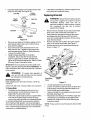
21" Self Starter
Rear-Discharge
Lawn Mower
Model Series
440 Series
IMPORTANT:
Read safety rules and instructions
carefully
before operating
equipment.
Warning:
This unit is equipped with an internal combustion engine and should not be used on or near any unimproved forestcovered, brush-covered or grass-covered land unless the engine's exhaust system is equipped with a spark arrester meeting
applicable local or state laws (if any). If a spark arrester is used, it should be maintained in effective working order by the operator.
In the State of California the above is required by law (Section 4442 of the California Public Resources Code). Other states may have
similar laws. Federal laws apply on federal lands. A spark arrester for the muffler is available through your nearest engine authorized
service dealer or contact the service department, P.O. Box 368022 Cleveland, Ohio 44136-9722.
MTD PRODUCTS
INC. P.O. BOX 368022
CLEVELAND,
OHIO 44136-9722
ECO #
PRINTED IN U.S.A.
FORM NO. 770-10478
(12/2000)
TABLEOFCONTENTS
Content
Page
Important Safe Operation Practices ...................................................................
3
Slope Gauge ......................................................................................................
6
Unpacking ..........................................................................................................
7
Assembling Your Lawn Mower ...........................................................................
7
Know Your Lawn Mower ....................................................................................
10
Operating Your Lawn Mower .............................................................................
10
Maintaining Your Lawn Mower ...........................................................................
13
Servicing Your Lawn Mower ..............................................................................
14
Making Adjustments ..........................................................................................
16
Off- Season Storage ..........................................................................................
17
Troubleshooting
.................................................................................................
18
Parts List .............................................................................................................
20
FINDINGMODELNUMBER
This Operator's Manual is an important part of your new Lawn Mower. It will help you assemble, prepare
and maintain the unit for best performance. Please read and understand what it says.
Before you start assembling your new equipment, please locate the model plate on the
equipment and copy the information from it in the space provided below. The information on
the model plate is very important if you need help from our Customer Support Department or
an authorized dealer.
You can locate the model number by standing behind the unit in the operating position and looking
down at the rear of the deck. A sample model plate is explained below. For future reference, please
copy the model number and the serial number of the equipment in the space below.
(Model Number)
(Serial Number)
Copy the model number here:
Copy the serial number here:
._'_[[C
MTD PRODUCTS ,NC
LEVELAND, OHIO 44136
CALLINGCUSTOMER
SUPPORT
If you have difficulty assembling this product or have any questions regarding the controls, operation or
maintenance of this unit, please call the Customer Support Department.
Call 1- (330) 220-4MTD (4683) or 1- (800)-800-7310 to reach a Customer Support
representative. Please have your unit's model number and serial number ready when you
call. See previous section to locate this information. You will be asked to enter the serial
number in order to process your call.
2
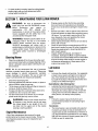
SECTION1: IMPORTANTSAFEOPERATION
PRACTICES
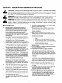
WARNING:
This symbol points out important safety instructions which, if not followed, could endanger
the personal safety and/or property of yourself and others. Read and follow all instructions in this manual
before attempting to operate this machine. Failure to comply with these instructions may result in personal
injury. When you see this symbol--HEED ITS WARNING.
WARNING:
Engine exhaust, some of its constituents, and certain vehicle components contain or emit
chemicals known to State of California to cause cancer and birth defects or other reproductive harm.
WARNING:
This machine was built to be operated according to the rules for safe operation in this manual. As with
any type of power equipment, carelessness or error on the part of the operator can result in serious injury. This
machine is capable of amputating hands and feet and throwing objects. Failure to observe the following safety
instructions could result in serious injury or death.
GeneralOperation
1.
2.
3.
4.
5.
6.
7.
8.
9.
A missing or damaged discharge cover can cause blade
contact or thrown object injuries.
10. Many injuries occur as a result of the mower being pulled
over the foot during a fall caused by slipping or tripping.
Do not hold on to the mower if you are falling; release the
handle immediately.
11. Never pull the mower back toward you while you are
walking. If you must back the mower away from a wall or
obstruction first look down and behind to avoid tripping
and then follow these steps:
a. Step back from the mower to fully extend your
arms.
Read this operator's manual carefully in its entirety
before attempting to assemble this machine. Read,
understand, and follow all instructions on the machine
and in the manual(s) before operation. Be completely
familiar with the controls and the proper use of this
machine before operating it. Keep this manual in a safe
place for future and regular reference and for ordering
replacement pads.
This machine is a precision piece of power equipment,
not a plaything. Therefore, exercise extreme caution at all
times. Your unit has been designed to perform one job: to
mow grass. Do not use it for any other purpose.
Never allow children under 14 years old to operate this
machine. Children 14 years old and over should read and
understand the operation instructions and safety rules in
this manual and should be trained and supervised by a
parent. Only responsible individuals who are familiar with
these safe operation rules should use this machine.
Thoroughly inspect the area where the equipment is to
be used. Remove all stones, sticks, wire, bones, toys and
other foreign objects which could be tripped over or
picked up and thrown by the blade. Thrown objects can
cause serious personal injury. Plan your mowing pattern
to avoid discharge of material toward roads, sidewalks,
bystanders and the like. Also, avoid discharging material
against a wall or obstruction which may cause discharged
material to ricochet back toward the operator.
To help avoid blade contact or a thrown object injury, stay
in the operator zone behind the handles and keep
bystanders, helpers, children and pets at least 75 feet
from the machine while it is in operation. Stop machine if
anyone enters the area.
Always wear safety glasses or safety goggles during
operation and while performing an adjustment or repair to
protect your eyes. Thrown objects which ricochet can
cause serious injury to the eyes.
Wear sturdy, rough-soled work shoes and close-fitting
slacks and shirts. Shirts and pants that cover the arms
and legs and steel-toed shoes are recommended. Never
operate this machine in bare feet, sandals, slippery or
light weight (e.g. canvas) shoes.
Do not put hands or feet near rotating parts or under the
cutting deck. Contact with the blade can amputate hands
and feet.
b.
c.
Be sure you are well balanced with sure footing.
Pull the mower back slowly, no more than half way
toward you.
d. Repeat these steps as needed.
12. Do not operate the mower while under the influence of
alcohol or drugs.
13. Do not engage the self-propelled mechanism on units so
equipped while starting engine.
14. The blade control handle is a safety device. Never
attempt to bypass its operation. Doing so makes the
safety device inoperative and may result in personal
injury through contact with the rotating blade. The blade
control handle must operate easily in both directions and
automatically return to the disengaged position when
released.
15. Never operate the mower in wet grass. Always be sure of
your footing. A slip and fall can cause serious personal
injury. If you feel you are losing your footing, release the
blade control handle immediately and the blade will stop
rotating within three seconds.
16. Mow in daylight or good artificial light. Walk, never run.
17. Stop the blade when crossing gravel drives, walkways
or roads.
18. If the equipment should start to vibrate abnormally, stop
the engine and check immediately for the cause.
Vibration is generally a warning of trouble.
19. Shut the engine off and wait until the blade comes to a
complete stop before removing the grass catcher or
unclogging the chute. The cutting blade continues to
rotate for a few seconds after the engine is shut off.
Never place any part of the body in the blade area until
you are sure the blade has stopped rotating.
3
20. Never
operate mower without proper trail shield,
discharge cover, grass catcher, blade control handle or
other safety protective devices in place and working.
Never operate mower with damaged safety devices.
Failure to do so, can result in personal injury.
21. Muffler and engine become hot and can cause a burn. Do
not touch.
5.
6.
Keep children away from hot or running engines. They
can suffer burns from a hot muffler.
Never allow children under 14 years old to operate a
power mower. Children 14 years old and over should
read and understand the operation instructions and
safety rules in this manual and should be trained and
supervised by a parent.
22. Only use parts and accessories made for this machine by
Service
the original equipment manufacturer (O.E.M). Failure to
do so can result in personal injury.
23. If situations occur which are not covered in this manual,
use care and good judgment. Contact your dealer for
assistance. Telephone 1-800-800-7310 for the name of
your nearest dealer.
Safe Handlingof Gasoline:
1.
SlopeOperation
2.
3.
4.
Slopes are a major factor related to slip and fall accidents
which can result in severe injury. Operation on slopes
requires extra caution. If you feel uneasy on a slope, do not
mow it. Before operating this unit on a slope or hilly area, use
the slope gauge on page 6 to measure slopes. If the slope is
greater than 15 degrees, do not mow it.
5.
go:
1.
2.
3.
Mow across the face of slopes; never up and down.
Exercise extreme caution when changing direction on
slopes.
Watch for holes, ruts, rocks, hidden objects, or bumps
which can cause you to slip or trip. Tall grass can hide
obstacles.
6.
7.
Always be sure of your footing. A slip and fall can cause
serious personal injury. If you feel you are losing your
balance, release the blade control handle immediately,
and the blade will stop rotating within 3 seconds.
8.
9.
OoNot:
1.
2.
3.
Do not mow near drop-offs, ditches or embankments,
you could lose your footing or balance.
Do not mow slopes greater than 15 degrees as shown on
the slope gauge.
Do not mow on wet grass. Unstable footing could cause
slipping.
10.
11.
12.
13.
Children
Tragic accidents can occur if the operator is not alert to the
presence of children. Children are often attracted to the
mower and the mowing activity. They do not understand the
dangers. Never assume that children will remain where you
last saw them.
1.
2.
14.
15.
Keep children out of the mowing area and under the
watchful care of a responsible adult other than the
operator.
Be alert and turn mower off if a child enters the area.
3.
Before and while moving backwards, look behind and
down for small children.
4.
Use extreme care when approaching blind corners,
doorways, shrubs, trees, or other objects that may
obscure your vision of a child who may run into the
mower.
To avoid personal injury or property damage use extreme
care in handling gasoline. Gasoline is extremely
flammable and the vapors are explosive. Serious
personal injury can occur when gasoline is spilled on
yourself or your clothes which can ignite.
Wash your skin and change clothes immediately.
Use only an approved gasoline container.
Never fill containers inside a vehicle or on a truck or
trailer bed with a plastic liner. Always place containers on
the ground away from your vehicle before filling.
If possible, remove gas-powered equipment from the
truck or trailer and refuel it on the ground. If this is not
possible, then refuel such equipment on a trailer with a
portable container, rather than from a gasoline dispenser
nozzle.
Keep the nozzle in contact with the rim of the fuel tank or
container opening at all times until fueling is complete. Do
not use a nozzle lock-open device.
Extinguish all cigarettes, cigars, pipes and other sources
of ignition.
Never fuel machine indoors because flammable vapors
will accumulate in the area.
Never remove gas cap or add fuel while the engine is hot
or running. Allow engine to cool at least two minutes
before refueling.
Never over fill fuel tank. Fill tank to no more than Y2inch
below bottom of filler neck to provide space for fuel
expansion.
Replace gasoline cap and tighten securely.
If gasoline is spilled, wipe it off the engine and
equipment. Move unit to another area. Wait 5 minutes
before starting the engine.
Never store the machine or fuel container inside where
there is an open flame, spark or pilot light as on a water
heater, space heater, furnace, clothes dryer or other gas
appliances.
To reduce fire hazard, keep mower free of grass, leaves,
or other debris build-up. Clean up oil or fuel spillage and
remove any fuel soaked debris.
Allow a mower to cool at least 5 minutes before storing.
GeneralService:
1.
2.
4
Never run an engine indoors or in a poorly ventilated
area. Engine exhaust contains carbon monoxide, an
odorless and deadly gas,
Before cleaning, repairing, or inspecting, make certain
the blade and all moving parts have stopped. Disconnect
the spark plug wire and ground against the engine to
prevent unintended starting.
3. Check
thebladeandengine
mounting
boltsatfrequent
intervals
forproper
tightness.
Also,visually
inspect
blade
fordamage
(e.g.,bent,cracked,
worn)Replace
blade
withtheoriginal
equipment
manufacture's
(O.E.M.)
blade
only,listedinthismanual.
"Useofpartswhichdonot
meettheoriginal
equipment
specifications
mayleadto
improper
performance
andcompromise
safety!"
4. Mower
blades
aresharp
andcancut.Wrapthebladeor
weargloves,
anduseextracaution
whenservicing
them.
5. Keepallnuts,bolts,andscrews
tighttobesurethe
equipment
isinsafeworking
condition.
6. Never
tamper
withsafety
devices.
Check
theirproper
operation
regularly.
7. Afterstriking
aforeign
object,
stoptheengine,
disconnect
thesparkplugwireandground
against
theengine.
Thoroughly
inspect
themower
foranydamage.
Repair
thedamage
before
starting
andoperating
themower.
8. Never
attempt
tomakeawheelorcutting
height
adjustment
whiletheengine
isrunning.
9. Grass
catcher
components,
discharge
cover,andtrail
shieldaresubject
towearanddamage
whichcould
expose
moving
partsorallowobjects
tobethrown.
Forsafety
protection,
frequently
checkcomponents
and
replace
immediately
withoriginal
equipment
manufacturer's
(O.EM.)partsonly,listedinthismanual.
"Useofpartswhichdonotmeettheoriginal
equipment
specifications
mayleadtoimproper
performance
and
compromise
safety!"
10. Donotchange
theengine
governor
setting
oroverspeed
theengine.
Thegovernor
controls
themaximum
safe
operating
speed
oftheengine.
11. Maintain
orreplace
safety
andinstruction
labels,as
necessary.
12.Observe
proper
disposal
lawsandregulations.
Improper
disposal
offluidsandmaterials
canharmthe
environment.
13.DONOTattempt
anymaintenance
orservice
tothe
engine
andormower
equipment
withthesafety
keyinthe
unlocked
andorenergize
mode.
14.ALWAYS
de-energize
selfstarter
priortoperforming
any
maintenance
orservice
totheengine
andormower.
Follow
instructions
ontheengine
andormachine
todeenergize
starter.
YourResponsibility
Restrict the use of this power machine to persons who read, understand
this manual and on the machine.
and follow the warnings and instructions
in
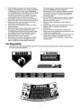
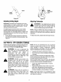
SIGHT AND HOLD THIS LEVEL WITH A VERTICAL TREE
| "_
Do not mow on inclines with a slope in excess of 15 degrees (a rise
could overturn and cause serious injury. If operating a walk-behind
your footing and you could slip, resulting in serious injury.
Operate RIDING mowers up and down slopes, never across the face
Operate WALK-BEHIND mowers across the face of slopes, never up
A POWER POLE
of approximately 2-1/2 feet every 10 feet). A riding mower
mower on such a slope, it is extremely difficult to maintain
of slopes.
and down slopes.
SECTION3: UNPACKING
RemovingUnitFromCarton
•
Remove staples, break glue on top flaps or cut tape
at carton end and peel along top flap to open
carton.
•
Remove loose parts if included with unit (i.e.,
operator's manual, hardware pack etc.).
Cut corners and lay carton down flat. Remove
packing material.
Roll or slide unit out of carton. Check carton
thoroughly for loose parts.
SECTION4: ASSEMBLING
YOURLAWNMOWER
NOTE: Make sure not to crimp the cables while
removing the loose parts or the entire unit from the
carton.
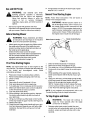
AssemblingHandle
•
NOTE: Reference to right or left hand side of the mower
is observed from the operating position.
For shipping purposes, the grass bag was placed
on top of the unit. Remove it from the unit and set it
out of the way. See Figure 2.
Lower Handle
Tools Required
•
Pair of Pliers
•
Funnel
•
Set of adjustable wrenches
Upper Handle
Lift lower handle
Grass Bag
/
Lift u
WARNING."
Disconnect
the spark
plug
wire and ground it against the engine to
prevent unintended starting. Leave safety key
in locked position.
Figure 2
Disconnecting
SparkPlug
•
•
Before setting up your lawn mower, disconnect the
spark plug wire from the spark plug, and ground it to
a bolt, retaining post or V-slot on the engine. See
Figure 1.
•
•
Spark Plug
Raise the lower handle, as shown in Figure 2, until
it snaps into place.
Raise the upper handle as shown in Figure 2.
Tighten the two wing nuts which are already on the
handle. See Figure 3.
_/pper
Haordle_
Handle
Tighten
Figure 1
Wing Nut
Fi ure 3
NOTE: Make sure to route the cables outside the lower
handle. Also do not crimp the cables while lifting the
handle up.
For shipping purposes, the hairpin clip is placed in
the outer hole of the weld pin on the lower handle.
Remove the hairpin clip from the outer hole of the
weld pin.
7
GrassCatcherAssembly
Using a pair of pliers, insert the hairpin clip into the
inner hole in the weld pin. Repeat on the other side.
See Figure 4.
NOTE: Make certain the grass bag is turned right side
out before assembling (warning label will be on the
outside).
Move hairpin clip to
this hole --'_
SoflGrass Bag
Parts for soft grass bag:
Weld
Pin
1. Front Frame
2. Rear Frame
3. Bag
Assembling soft grass bag:
Handl_
Figure 4
•
Insert post of cable ties that are on lower handle
into the holes provided on the lower handle. The
holes may be on the inside or outside. Pull cable
ties tight and cut off the extra. See Figure 5 below.
Cable Tie
•
•
Post on
Join the rear frame and front frame assembly as
shown in Figure 7A.
Place the bag over the frame (black plastic side is
the bottom of bag). Slip the openings in the side of
the plastic channels on the bag over the hooks on
the grass catcher frame.
Secure bag to frame by working the plastic
channels on bag over frame as shown in Figure 7B.
All of the plastic channels except the center top of
the bag attach from the outside of bag. The center
top of the bag attaches from inside the bag.
Hook
Figure 5
Frame
Assembly
Attaching
StarterRope
The rope guide is already attached to the right side of
the upper handle of your mower. See Figure 6.
•
•
Rear
Frame
With the spark plug wire disconnected and
grounded, and with the safety key in the locked
position, pull the starter rope up to the rope guide.
See Figure 6.
Slip the rope through the rope guide as shown
below. Tighten the wing nut holding the rope guide
to the upper handle.
Plastic
Channels
Figure 7
AttachingGrassCatcher
If your mower is equipped with a mulching plug,
and it is in place on the mower, lift the rear
discharge door and remove the rear mulching plug
from the mower. See Figure 8.
Blade Control
Handle
Upper Handle
Rear
Mulching
Plug
Rope Guide
Figure 8
NOTE: Make sure that the cables are routed to the
outside of the handle when attaching the grass catcher.
Figure 6
8
Lift the rear discharge door.
Place the hooks of the grass catcher into the slots
in the handle bracket assemblies on both sides.
See Figure 9. Release the rear discharge door.
•
Slide the rod into the upper edge of the chute
deflector so the tab on the rod is toward the left side
of the chute deflector. When assembled correctly,
the rod will extend further to the left side than the
right side. See Figure 10.
Slide the push nut onto the right side of the rod to
secure.
AttachingChuteDeflector
•
•
Lift the rear discharge door on the mower.
Place the ends of the rod into the slots in the handle
•
bracket assemblies. See Figure 11.
Release the rear discharge door.
Rear
Rear
Door
!
Door
Figure 9
RemovingGrassCatcher
•
Lift the rear discharge door on the mower.
Lift the grass catcher up, out of the slots in the
handle bracket assemblies.
•
Reinstall the plastic rear mulching baffle.
•
Release the rear discharge door.
WARNING:
Never operate
the mower
unless the hooks on the grass catcher are
seated in the slots on the handle bracket
assemblies,
rests firmly
catcher.
and the rear discharge door
against the top of the grass
ChuteDeflector(ifequipped)
If your mower is equipped with the chute deflector,
assemble as follows:
Rod
Chute
Push
Nut
Figure 10
Slots in
Handle Bracket
Assemblies
Figure 11
Convertingto Mulcher
•
Lift the rear discharge door.
•
Remove the grass bag or chute deflector.
•
Insert the mulch plug. See Figure 8.
•
Release the rear discharge door. See Figure 9.
SECTION5: KNOWYOURLAWNMOWER
WARNING:
safety device. Never attempt to bypass its
operations. Doing so, may result in personal
injury through contact with the rotating blade.
The blade rotates whenever the engine is
running and when the self starter is deenergized.
and their proper Be
operation.
to stop
WARNING:
familiar Know
with how
all controls
the machine and disengage them quickly.
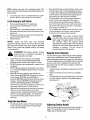
Drive Control
Blade Control Handle
Lever_
Start Control Button
,_
Recoil
Starter
The blade control handle is a
Upper Handle
DriveClutch Control
Lower Handle
The drive control lever is located on the upper handle
and is used to engage the drive. Squeeze the lever
against the upper handle to engage the drive; release
the drive control lever to slow down or stop the mower
from propelling.
Grass Bag
Rear Discharge Door
Safety Key
The safety key is located on the engine. See Figure 12.
The safety key is a safety device used to activate and
deactivate the self starter system. The self starter
system will not work without the key in its proper
position. See engine manual for further information
pertaining to the safety key.
SaLt
Cuttir
Adjustment
NOTE: The safety key must be in the run position to
start the mower for both systems, either the self starter
or recoil starter.
Figure 12
Recoil Starter
Start Control Button
The recoil starter handle is attached to the upper
handle. See Figure 12. The recoil starter is used to start
the engine when the self starter is in the de-energized
mode.
The start control button is located on the upper left side
of the handle. See Figure 12. The start control button
must be depressed fully while pulling the blade control
handle toward the upper handle for the engine to start.
The starter control button will automatically return to the
off/up position once the blade control handle is
released.
Primer
The primer is used to pump gas into the carburetor. Use
it to assist in starting a cold engine, but do not use it
when restarting a warm engine after a short shutdown.
Refer to engine manual for location of the primer,
NOTE: The starter button must be depressed to start
the engine with either the self starter or recoil starting
system.
BladeControlHandle
The blade control handle is located on the upper handle
of the mower. The blade control handle and starter
control button must be depressed in order to operate
the unit. Release the blade control handle to stop the
engine and the blade and to energize the self starter.
SECTION6: OPERATING
YOURLAWNMOWER
The operation of any lawn mower can result in foreign
objects being thrown into the eyes, which can result in
severe eye damage. Always wear safety glasses or eye
shields.
all
instructions and
warnings
on theand
machine
WARNING:
Read,
understand,
follow
and in this manual before operating.
Keep hands and feet away from the discharge area on
and from under the cutting deck. See safety labels on
page 5.
NOTE: For best results raise the cutting position until it
is determined which height is best for your lawn. See
Cutting Height Adjustment Section.
10
14. if engine does not start by the second pull, repeat
steps 8, 9,10, 11 and 12.
GasandOilFill-Up
WARNING:
Use
extreme
care
when
SecondTimeStartingEngine
handling gasoline. Gasoline is extremely
flammable and the vapors are explosive.
Never fuel machine indoors or while the
NOTE: Follow these instructions
already in the energized mode.
engine
is hot or
running.
Extinguish
cigarettes, cigars, pipes, and other sources of
ignition.
WARNING:
NEVER assume starter is in
the de-energized mode, even if the key is in
the locked position and/or removed from the
engine. ALWAYS de-energize starter prior to
performing any maintenance or service to the
engine and/or mower. Follow instructions on
the engine and/or machine to de-energize.
Service the engine with gasoline and oil as
instructed in the separate engine manual packed
with your mower. Read the instructions carefully.
BeforeStartingMower
_,
if the self starter is
Blade Control Handle
all instructions and
warnings
on theand
machine
WARNING:
Read,
understand,
follow
Starter Control Button
and in this manual before operating.
Attach spark plug wire to spark plug. Make certain
the metal cap on the end of the spark plug wire
(inside the rubber boot) is fastened securely over
the metal tip on the spark plug.
Check the drive clutch control for proper
adjustment. If the mower does not propel itself or
the drive wheels hesitate with the drive clutch
engaged, perform the drive clutch control
adjustment as instructed on page 16.
Figure 13
FirstTimeStartingEngine
1.
2.
3.
4.
NOTE: Use recoil starter rope to start engine for the
very first time. The mower is shipped with the safety key
in the locked and de-energized
mode,
follow
instructions as follows.
1.
2.
3.
4.
5.
Place lawn mower on a level surface outdoors.
Remove clear plastic packaging under fuel cap.
Check oil level.
Add fuel.
6.
5.
6.
7.
8.
Open shut off valve (if equipped) 1/4 turn.
Push spark plug wire firmly on spark plug.
Turn safety key 1/4 turn clockwise to RUN position.
Make sure that the drive clutch control is adjusted
so the drive belt is as loose as possible.
9. Push the primer three times.
10. While standing in the operating position, depress
the starter control button fully with the thumb of
your right hand.
11. Using your left hand, pull the blade control handle
all the way toward the upper handle. See Figure 13.
12. Release the button.
Check oil level and add fuel, if necessary.
Open shut off valve (if equipped) 1/4 turn.
Turn safety key 1/4 turn clockwise to RUN position.
Firmly push primer bulb 3 times (for a cold engine
only!).
While standing at the upper handle, depress the
starter control button with the thumb of your right
hand.
Using your left hand, pull the blade control handle
all the way toward the upper handle. See Figure 13.
Starter will de-energize and engine will start.
(NOTE: if engine does not start, release the blade
control handle and follow steps 8, 9, 10, 11 and 12
in the "First Time Starting Engine instructions.
NOTE: If any problems are encountered, refer to the
Trouble Shooting Guide for helpful information.
To StopEngineandBlade
_,
13. Grasp the recoil rope starter handle with your right
hand and slowly pull towards you until feel a slight
resistance, then pull firmly until your arm is fully
extended.
1.
11
rotate for threeThe
seconds
the blade
WARNING:
blade after
will continue
to
control lever is released.
Release safety blade control handle (the start
control button will automatically return to the off/up
position), engine and blade will stop within a few
seconds.
•
NOTE: Engine may stop with a racketing sound. This
sound is the self starter being reactivated/energized for
the next start.
2.
Be sure that the lawn is clear of stones, sticks, wire,
or other objects which could damage lawn mower
or engine. Such objects could be accidently thrown
by the mower in any direction and cause serious
personal injury to the operator and others.
For best results, do not cut wet grass because it
tends to stick to the underside of the mower,
Turn safety key 1/4 turn counterclockwise to LOCK
position. Remove key and store in a safe place.
To De-EnergizeSelfStarter
•
•
Remove spark plug wire from spark plug.
Turn safety key to RUN position (1/4 turn
clockwise).
While standing in the operating position, depress
the starter control button fully with the thumb of your
right hand.
Using your left hand, pull the control handle all the
way toward the upper handle.
Release button.
•
preventing proper discharge of grass clippings,
poor mulching conditions, and could cause you to
slip and fall. New grass, thick grass, or wet grass
may require a narrower cut.
For a healthy lawn, always cut off one-third or less
of the total length of the grass. Lawn should be
trimmed in fall as long as there is growth.
•
WARNING:
If you strike a foreign object,
stop the engine. Remove spark plug wire from
spark plug, thoroughly inspect the mower for
any damage. Repair the damage before
restarting and operating the mower. Extensive
vibration of the mower during operation is an
indication of damage. The unit should be
promptly inspected and repaired.
NOTE:
Engine will crank over upon actuating
equipment starting controls, but will not spark if spark
plug wire was removed from spark plug as described
above. Once engine has stopped cranking, self starter
is de-energized.
,_
•
•
•
BaggingGrassClippings
instructions areSelf
not Starting
followed,System:
amputation
or
WARNING:
If these
severe laceration can result.
You can use the grass catcher bag to collect clippings
while you are operating the mower. Attach the grass
catcher following instructions on page 8 of this manual.
The grass clippings will automatically collect in the bag
as you run the mower. Operate the mower until the
grass bag is full. Do NOT allow the bag to overfill with
grass clippings.
ALWAYS disconnect spark plug, de-energize
starter, lock and remove safety key BEFORE
performing ANY service to the engine or mower.
DO NOT attempt any maintenance or repairs to the
self starter.
NEVER assume starter is de-energize, even if key
is in LOCK AND REMOVE position and/or removed
from engine.
BEFORE removing grass or other debris from
under mower deck; BEFORE changing oil, air filter
or spark plug; BEFORE removing blade for
servicing; BEFORE performing any other service to
engine or mower; BEFORE transporting mowerALWAYS DE-ENERGIZE SELF STARTER.
ALWAYS lock and remove safety key and store in a
safe place until next use. The safety key is
designed and intended to be removed from engine
when not in use. Removing key will prevent
unsupervised or unexpected starting of mower by
children or unsuspecting adults. The safety key
must be in the locked position before it can be
removed.
Stop the engine completely by releasing the control
handle.
•
Make sure that the unit has come to a complete
stop.
Lift discharge door and pull grass bag up and away
from the mower to dispose of the grass clippings
See Figure 14.
Figure 14
UsingYourlawnMower
•
•
Do not operate the mower without the mulching
cover, the grass catcher bag, or the discharge
chute properly installed.
AdjustingCuttingHeight
Refer to height adjustments section of this manual on
page 17 for instruction on how to adjust the cutting
height and the handle height.
12
•
For best results in mowing, keep the cutting height
position high until you have determined which
cutting height is preferred.
SECTION7: MAINTAININGYOURLAWNMOWER
,4_,
•
Change engine oil after the first two operating
hours and every 25 operating hours thereafter.
Check the oil level before starting the engine every
time.
•
Service foam filter in the air cleaner every 25 hours
of use and replace the paper filter component every
100 hours. You may have to service the air filter
more frequently if you are operating the mower
under extremely dusty conditions.
Clean engine periodically. Remove dirt and debris
with a cloth or brush.
spark
plug wire Be
andsure
DE-ENERGIZE
WARNING:
to disconnectstarter
the
before
performing
any
repairs
or
maintenance.
DO
NOT
attempt
any
maintenance or service to the engine and/or
mower equipped with the safety key in the
unlocked and/or energized mode.
WARNING:
NEVER assume starter is de-
energized, even if the key is in the locked
position and/or removed from the engine.
ALWAYS de-energize self starter prior to
performing any maintenance or service to the
engine and/or mower. Follow instructions on
the engine and/or machine to de-energize
starter.
•
•
•
CleaningMower
•
Clean the underside of the mower deck after each
use to prevent any build-up of grass clippings. If this
debris is allowed to accumulate, it will result in rust
and corrosion.
Lubrication
NOTE: We do not recommend the use of pressure
washers or garden hose to clean your unit. These may
cause damage to electric components,
spindles,
pulleys, bearings or the engine. The use of water will
result in shortened life and reduced serviceability.
•
•
•
•
Clean the spark plug and reset the gap to.030" at
least once a season or every 50 hours of operation.
Spark plug replacement is recommended at the
start of each season.
Inspect muffler periodically, and replace if
necessary. Damaged mufflers or spark arresters
can create a fire hazard. Make sure to avoid muffler
and surrounding areas while the mower engine is
hot because temperature of these areas of the
engine may exceed 150 ° F.
Wheels
Lubricate the wheels and bearings, if so equipped,
at least once a season with light oil or engine oil.
Also, if the wheels are removed for any reason,
lubricate the surface of the axle bolt and the inner
surface of the wheel with light oil.
Disconnect spark plug wire.
Drain the gasoline from the lawn mower, or place a
piece of plastic under the gas cap.
Tilt the mower so that the side with the air cleaner is
ChuteDeflector & Rear DischargeDoor
Lubricate the torsion spring and the pivot point on
each end of the chute deflector and the rear
discharge door using a light oil. This will prevent
rusting and ensure that the deflector, which is a
safety device, can always work properly.
facing up. Hold the mower firmly.
Scrape and clean the underside of the deck with a
suitable tool. Do not spray with water.
Put the mower back on its wheels. If you had put
plastic under the gas cap, remove it now.
Engine
Follow the engine manual instructions and
recommended schedule for lubricating engine
components.
WARNING:
Never tip the mower more than
90 degrees in any direction and do not leave
the mower tipped for any length of time. Oil
can drain into the upper part of the engine
causing a starting problem.
Transmission
•
EngineMaintenance
A list of key maintenance jobs required for good
performance by the mower is given below. Follow the
accompanying engine manual for detailed list and
instructions.
13
The transmission is pre-lubricated and sealed at
the factory and does not require lubrication on a
regular basis as part of maintenance. However, if
you disassemble the transmission for any reason,
refill with two ounces of Alvania grease (part # 7370168A) as part of reassembly.
Pivot Points
Lubricate the pivot points on the blade control
handle, brake cable and the cutting height
adjustment lever at least once a season with light
oil. The blade control handle must operate freely in
both directions. The cutting height adjustment
levers should be able to move easily.
Lubricate
/
Figure 15
SECTION8: SERVICING
YOURLAWNMOWER
WARNING:
,_
When removing the cutting
blade for sharpening or replacement, protect
hands by using heavy gloves or a thick rag to
grasp the cutting blade.
WARNING:
to disconnectstarter
the
spark plug wire Be
andsure
DE-ENERGIZE
before lubricating, repairing, or servicing. DO
NOT attempt any maintenance or service to
the engine and/or mower equipped with the
safety key in the unlocked and/or energized
mode.
WARNING:
•
•
Disconnect spark plug wire from spark plug.
Turn mower on its side making sure that the air filter
and the carburetor are up.
To RemoveBlade:
NEVER assume starter is de-
•
energized, even if the key is in the locked
position and/or removed from the engine.
ALWAYS de-energize self starter prior to
performing any maintenance or service to the
engine and/or mower. Follow instructions on
the engine and/or machine to de-energize
starter.
•
•
Remove the bolt and the bell washer that hold the
blade-pulley assembly to the engine crankshaft.
See Figure 16. Remove the assembly from the
crankshaft.
Remove the two bolts and lock nuts from the blade
assembly.
Remove the blade from blade adapter and pulley.
To ReplaceBlade:
BladeCare
Before reinstalling the blade-pulley assembly to the
unit, lubricate the engine crankshaft and the inner
surface of the blade adapter with light oil.
Also lubricate the bolt holes, bolt and the inner
surface of the nuts.
WARNING:
Periodically inspect the blade
adapter and pulley for cracks, especially if you
strike a foreign
object. Replace
when
necessary.
14
Install the blade adapter on the pulley with the "star"
away from the pulley. See Figure 16.
Lock Nut
Pulley
_
Blade
m_
Adapter _
•
ReplacingDriveBelt
Assembly
___
Lock Nut
,_
_;_
_
If the blade is not balanced, remove metal from the
heavy side until it balances evenly.
!Blade
•
/_
Bell F \Hex
Washer
Hex Bolt
Bolt
Figure 16
•
Place the new blade on the blade adapter with the
side marked bottom (has a part number) facing
away from the adapter.
Secure the blade to the assembly with two hex
bolts and lock nuts. Tighten the hex bolts to the
recommended torque. Refer to 'Blade Mounting
Torque' information below.
Install the blade assembly on the engine
crankshaft. Secure with the hex bolt and bell
•
and ground it Disconnect
WARNING:
against the the
engine
sparktoplug
prevent
wire
unintended
starting.
Drain fuel into an
approved container or place a piece of plastic
film underneath the gas cap to prevent
gasoline from leaking.
Remove the two shoulder screws securing the front
drive cover to the mower deck. See Figure 17.
Press inward on the sides of the front drive cover
and release the tabs that secure the front drive
cover to the height adjuster brackets. Remove drive
cover from the mower.
Remove the idler and hardware from idler bracket
using 7/16" wrench and socket. See Figure 17.
Remove the belt from the transmission pulley as
shown in Figure 17.
Bracket
Drive BelL\
washer (cupped side of washer to blade) and
tighten to the recommended torque. Refer to 'Blade
Mounting Torque' information below.
Lock Nut
IMPORTANT: The bolt used to secure the blade to the
/Y
engine is specially heat-treated. Do not substitute. To
order replacement bolt, refer to the parts list in the back
of this manual.
_
your
ARNING:
unit, all nuts
To and
ensure
bolts safe
must operation
be checked
of
periodically for correct tightness.
/
Front Drive
Cover
BladeMountingTorque:
Blade adapter bolts: 120 in.lbs, minimum, 150 in.lbs.
maximum.
Figure 17
•
•
Center bolt: 450 inJbs, minimum, 600 in.lbs, maximum.
To SharpenBlade:
•
Shoulder
Screw
The blade can be sharpened with a file or on a
grinding wheel. Do not attempt to sharpen the
blade while it is still on the mower.
•
Follow the original angle of grind as a guide. Make
sure that each cutting edge receives an equal
amount of grinding to prevent an unbalanced blade.
An unbalanced blade will cause excessive vibration
when rotating at high speeds, may cause damage to
the mower and could break, and may causing personal
injury. Test the blade by balancing it on a round shaft
screwdriver or a blade balancer.
Lift and stabilize the front of the deck.
Loosen the center hex bolt and lower the blade and
engine pulley until there is adequate clearance to
move the belt past the belt keeper.
Remove the belt from the engine pulley and around
the blade. See Figure 18.
Reassemble new belt (part # 754-0465). Begin idler
reassembly by inserting bolt up through the idler
bracket hole. Adjust the drive clutch following the
instructions below.
NOTE: Torque center hex bolt to between 450 and 600
in. Ibs.
15
Right Front
Wheel \
Left Front
/J Wheel
Pulley _ /
//
Engine _
Bolt
Figure 18
SECTION9: MAKINGADJUSTMENTS
WARNING:
Be sure
to disconnect
the
spark plug wire and DE-ENERGIZE starter
before performing any adjustments or repairs.
DO NOT attempt any maintenance or service
to the engine and/or mower equipped with the
safety key in the unlocked and/or energized
mode.
WARNING:
cable
Ad
To tighten
NEVER assume starter is de-
To
cable
energized, even if the key is in the locked
position and/or removed from the engine.
ALWAYS de-energize self starter prior to
performing any maintenance or service to the
engine and/or mower. Follow instructions on
the engine and/or machine to de-energize
starter.
Figure 19
AdjustingHandleHeight
Your mower is shipped with the handle in the higher
height position. To lower height, proceed as follows.
AdjustingDriveClutchControl
•
•
The drive clutch adjustment wheel is located on the
drive control lever housing and is used to tighten or
loosen tension on the drive cable. Perform this
adjustment if the following exists.
a. The mower does not propel itself with the
drive control lever engaged.
b. The mower's drive wheels hesitate with the
•
Remove the starter rope from the rope guide.
Remove the upper handle by removing the hand
knobs and carriage bolts. Lay the upper handle out
of the way, being careful not to bend or kink the
cables.
•
Remove the hairpin clips from the weld pins on the
handle brackets. Refer to Figure 4. Press out on the
legs of the lower handle. Remove lower handle
from the mower.
Turn the lower handle around so the notch on the
bottom of the lower handle is facing forward as
shown in Figure 20. Reassemble, placing the
bottom holes in the handle over the weld pins in the
handle mounting bracket.
Reassemble the upper handle to the lower handle.
Insert hairpin clips in the inner holes of the weld
pins and attach the starter rope as instructed in the
"Assembling Your Lawn Mower" section.
•
drive control lever engaged.
To resolve the above problems, rotate the
adjustment wheel with your fingers: clockwise to
tighten the cable, and counter-clockwise to loosen
the cable. See Figure 19.
•
16
\
Notch
Lower
Handle
Adjustment
Lever
_/
Figure 20
Figure 21
AdjustingCuttingHeight
AdjustingCarburetor
IMPORTANT: All wheels must be placed in the same
relative position. For rough or uneven lawns, move the
height adjustment lever to a higher position. This will
help stop scalping of the grass.
WARNING:
if any adjustments are made to
the engine (e.g. carburetor) while the engine is
running, keep clear of all moving parts. Be
careful of heated surface_ like the muffler.
An adjusting plate and thumb lever at each wheel
position provides cutting height adjustment. Each
adjusting plate has nine height positions. Height of cut
will change when you move the thumb lever from one
position to another.
NOTE: A dirty air cleaner may cause an engine to run
rough too. Make sure that the air cleaner is clean and
attached to the carburetor before deciding to adjust the
carburetor.
•
To adjust carburetor, please follow the engine manual.
Simply depress the lever towards the wheel and
move the lever assembly to desired position. See
Figure 21.
SECTION10: OFF-SEASON
STORAGE
Prepare your lawn mower for storage at the end of the
season or if the unit will not be used for 30 days or
more. Store the mower in a clean, dry area.
NOTE: We do not recommend the use of pressure
washers or garden hose to clean your uniL They may
cause damage to electric components,
spindles,
pulleys, bearings or the engine. The use of water will
result in shortened life and reduce serviceability.
spark plug wire Be
andsure
DE-ENERGIZE
WARNING:
to disconnectstarter
the
before
performing
any
repairs
or
maintenance.
DO
NOT
attempt
any
maintenance or service to the engine and/or
mower equipped with the safety key in the
unlocked and/or energized mode.
WARNING:
•
•
Lubricate the mower as instructed on page 13.
You can fold your mower's handle for convenience
of storage:
Remove the starter rope from the rope guide; loosen
the two hand knobs on the sides of the handle, and let
the upper handle fold down to the rear.
Move the hairpin clips to the outer hole in the weld pins
on the handle mounting brackets. Spread the sides of
the lower handle, and push it forward and down.
NEVER assume starter is de-
energized, even if the key is in the locked
position and/or removed from the engine.
ALWAYS de-energize self starter prior to
performing any maintenance or service to the
engine and/or mower. Follow instructions on
the engine and/or machine to de-energize
starter.
WARNING:
fuel continuator
Inspect and replace/sharpen blade, if required.
Refer to page 14.
Replace your gasoline can if it starts to rust. Rust
and/or dirt in the gasoline will cause problems.
Store unit in a clean, dry area. Do not store next to
corrosive materials, such as fertilizer or rocksalt.
Never store the machine or
indoors where there is an
NOTE: If storing the mower in an unventilated or metal
storage shed, make sure to rustproof the equipment
with a light oil or silicone.
open flame, spark or pilot light such as on
water heater, furnace, clothes dryer or other
gas appliance.
17
•
Engine
•
Clean engine and remove any grass clippings, dirt,
and debris from the cooling fins, air intake screen,
levers, linkage and the exterior of the engine.
•
Follow recommendations in the accompanying
engine manual for off-season storage of the
engine.
Change oil as stated in the engine manual.
SECTION11: TROUBLESHOOTING
GUIDE
Possible
ils to start
Corrective
Cause(s)
Blade control handle disengaged.
Start control button not depressed.
Spark plug wire disconnected,
Safety key not in run position.
Fuel tank empty, or stale fuel.
Blocked fuel line.
Faulty spark plug.
Engine flooded.
Engine not primed.
Self starter already de-energized.
Spark plug wire loose.
Blocked fuel line or stale fuel.
Engine runs erratic
Vent in gas cap plugged.
Water or dirt in fuel system.
Dirty air cleaner.
Carburetor out of adjustment.
Engine oil level low.
Engine overheats
Air flow restricted.
Carburetor not adjusted properly.
Occasional skip (hesitates) at Spark plug gap too close.
high speed
Idles poorly
Spark plug fouled, faulty or gap too
wide.
Carburetor improperly adjusted.
Dirty air cleaner.
Excessive vibration
[Cutting blade loose or unbalanced.
Bent cutting blade.
Mower will not mulch grass
Wet grass,
,
[Excessively
Engage blade control handle.
Depress starter control button.
Connect wire to spark plug.
Place safety key in run position.
Fill tank with clean, fresh gasoline.
Clean fuel line.
Clean, adjust gap or replace.
Wait a few minutes.
Push primer bulb three times to prime
engine.
Use recoil starter to start engine
Connect and tighten spark plug wire.
Clean fuel line; fill tank with clean, fresh
gasoline.
Clear vent.
Drain fuel tank. Refill with fresh fuel.
Clean air cleaner.
Adjust carburetor.
Fill crankcase with proper oil.
Remove blower housing and clean.
Adjust carburetor.
Adjust gap to .030".
Reset gap to .030" or replace spark plug.
Adjust carburetor.
Clean air cleaner.
Tighten blade and adapter. Balance blade.
Replace blade,
o not mow when grass is wet; wait until
later to cut.
high grass.
Mow once at a high cutting height, then
mow again at desired height or make a nar-
/
Uneven
cut
Action
Dull blade.
Wheels not positioned correctly.
Sharpen
or replace
rower cutting
swath blade.
(1/2 width).
Place all four wheels in same height position.
/
L
Dull blade.
_Sharpen or replace blade.
Refer to separate engine manual packed with your mower for more engine related information.
NOTE: For repairs beyond the minor adjustments listed above, contact your nearest authorized service dealer.
18
NOTES
19
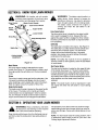
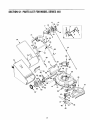
SECTION12: PARTSLISTFORMODELSERIES440
11
7
17
12
\
71
\
8
23
74
2O
14
26
21
28
22
73
53
52
"30
31
35
58
40
41
49
2O
ModelSeries440
Ref. No I
Part No.
Description
Ref.No !
I
1
2
3
4
5
6
7
8
9
10
11
12
13
14
15
16
17
18
19
20
21
22
23
24
731-1057
731-0620
731-1058
731-1059
710-1667A
746-0960
647-0058
749-1405
731-2532
1731-2533
1720-0428
1732-1171
1782-0156
1746-1141
1710-1256
1715-0168
1716-0209
1720-0279
1710-1205
1710-1174
1720-0314
1749-0928
1710-0501
1736-0451
25
26
27
1710-0324
1726-0240
1732-1172
28
29
3O
31
32
33
34
1711-1293
!631-0075B
1712-0271
1710-1008
1782-5004
1782-5003
1710-1017
35
36
37
38
39
J782-0080A
1782-5002
1712-0798
1736-0331
1710-0216
40
17510042824
Upper Drive Cover
Drive Lever
Lower Drive Cover
"_41
42
43
44
45
46
47
48
49
50
51
52
53
54
55
56
Mounting Cap
Screw #10-12:75
Drive Cable
Control Bail Lever
Upper Handle
Control Cover RH
Control Cover LH
Button
Compression
Lever
Spring
Control Cable 58.25" Lg.
Hi-Low Screw
Pin
Retention Ring
Knob
66
67
68
69
7O
71
72
73
74
75
J731-1937A
1754-0465
1712-0324
1756-1146A
/748-0411
1742-0741
1736-0452
1710-0606
1710-1257
1712-3005
1732-0677
1710-0192
1720-0275
1714-0104
1782-7000
682-0515A
/682-0516A
682-0511A
1682-0512A
1710-0896
14766
114765
1720-0190
1732-0417A
1738-0507B
1736-0105
734-1979
1734-1983
1738-0102
1731-1426
1732-0700
!731-1236
/732-0678
1720-0294
1782-5007A
/764-0457A
/764-0310
764-0311
-
737-0208
58
Eye Bolt 1/4-20
Carriage Bolt 5/16-18 x 2.0
Knob
Lower Handle
Hex Hd. Cap Screw
Saddle Washer
Hex Lock Nut 1/4-20
Cable Tie
59
60
61
62
63
64
65
Torsion Spring
Pin-Belt Keeper
Engine Spacer
Hex Nut 1/4-20 Thread
Tapp Screw w/Hex Lock Wash
Rear Baffle Right
Rear Baffle Left
Scr. AB: 1/4-14.625 Trust
Deck 21" RD
Front Baffle
Bell Washer .39 x 1.13 x .062
Hex Nut 3/.8-16
Hex Screw 3/8-16 x .75
Screw #12 x .457
21
Pad No.
Description
Front Drive Cover - Yellow
V-Belt
Hex Lock Nut 1/4-20
Drive Pulley
Blade Adapter
21" Mulching Blade w/star
Bell Washer ,396 I.D. x 1.140 O.D. x
Hex Screw 1/4-2 0x 1.50
Hex Screw 3/8-24 x 2.50
Hex Nut 3/8-16
Torsion Spring L,H.
Scr. Tr, Mach #10-24 x .380
Knob
Cotter Pin
Rear Discharge Door
Complete Handle Brkt Ass'y - LH
Complete Handle Brkt Ass'y - RH
Handle Brkt Ass'y - LH
Handle Brkt Ass'y - RH
Hex Screw w/wsh. 1/4-14 x .62
Pivot Bar - LH
Pivot Bar - RH
Knob
Spring Lever
Shldr Screw .500 Dia x .434 Long
Bell Washer ,380 x ,880 x .062
WhL Comp. 8 x 2 PI. (Rear)
Wh. Comp. 8 x 2 Fwd. (Front)
Shldr Screw .498 x 1.445
Hubcap: Radial Spoke Yellow
Wire
Rear Flap
Torsion Spring R.H.
Foam Grip (2 required)
Mulching Plug Baffle
Soft Top Grass Bag
Grass Catcher Frame (Rear)
Grass Catcher Frame (Front)
Bottle of Oil (not shown)
ModelSeries440
57
4O
37_
\
@
\
\13
46
I
I
J
J
J
2O
J
7
IMPORTANT:
For a proper working machine,
use]
Factory Approved Parts.
V-BELTS
are
specialty
designed
to engage
and]
disengage safety. A substitute (non OEM) V-Belt can be
dangerous
by not disengag ng compete
y.
/
53
52
._ /
4O
43
!
I
L
I
22
51
ModelSeries440
Bef. No
PaN No.
Bef. No
Description
PaN No.
Description
1.
712-3025
Hex Jam Nut 5/16-24
31.
741-0604
2.
736-0425
Bell Washer .325 x .930 x .045
32.
748-0355
Bearing Support
3.
756-1042
33.
736-0447
Wave Washer 1.5 x 1.0 x .029
4.
736-0425
Pulley, 3.82 x .313 x .68
Bell Washer .325 x .930 x .045
34.
782-0512B
RH Height Adj. Plate
5.
712-0896
Lock Nut 1/4-28
35.
782-0511A
LH Height Adj. Plate
6.
736-O4O6
Flat Washer .442 x 1.38 x .060
36.
682-0509
Pivot Plate Assembly
7.
782-7598
Belt Keeper
37.
732-0706
RH Front Lever
8.
741-0124
Ball Bearing
38.
732-0707
LH Front Lever
9.
721-0457
Oil Seal
39.
720-0190
Knob
10.
750-1050
Flange Spacer
40.
710-0216
Hex Cap Screw 3/8-16 x .75
11.
682-0028
Idler Bracket Assembly
41.
736-O474
Washer
12.
741-0682A
Bearing Sleeve
42.
716-0102
Snap Ring 1.0 dia.
13.
732-0849A
Flat Washer .504 x .700 x.030
43.
782-7551
Wheel Dust Cap
14.
710-0299
Hex Cap Screw 1/4-28 x 1.00
44.
717-1762
Gear 14T R.H.
15.
736-0570
Flat Washer .865 x 1.145 x .030
45.
717-1761
Gear 14T L.H.
16.
741-0699
Needle Bearing .438 x .625 x .500
46.
634-0021A
Wheel, 8x2 x 1.75
17.
721-0325
Plug 1/4 x .437
47.
731-1426
Hubcap: Yellow
18.
618-0300A
Upper Housing
48.
682-0512A
RH Height Adj. Complete
19.
721-0329
Oil Seal .500 x .687 x .094
49.
682-0511A
LH Height Adj. Complete
20.
741-0673
Flange Bearing
50.
682-0030
Cable Idler Bracket
21.
611-0105A
Output Shaft
51.
715-0221
Dowel Pin
22.
736-0520
Flat Washer .504 x .700 x .030
52.
736-3013
Flat Washer 1/2 x 1.00 x .063
23.
717-1492
Pinion Shaft 10T
53.
714-0101
Cotter Pin .08 x 1.42
24.
736-0314
Thrust Washer .375 x .70 x .030
54.
738-1002
Screw
25.
736-0569
Thrust Washer .388 x .625 x .062
55.
754-0465
Belt
26.
618-0299A
Lower Housing
56.
716-0865
Snap Ring
27.
741-0672
Flange Bearing .378 x .531 x .370
57.
750-1165
Slev. Spacer
28.
710-1276
Hex Screw w/Washer 1/4-20 x .750
58.
750-1166
Slev. Spacer
29.
618-0606
Transmission Assembly Comp.
(Includes Ref. # 1to Ref. #30)
59.
736-0331
Bell Washer
60.
712-0798
Hex Nut 3/8-16
30.
732-O7O8
Bearing Retainer
23
Bearing Sleeve .50 I.D.
DD 1.5" O.D.
MANUFACTURER'S
LIMITED WARRANTY
FOR:
YaRD-MaN_)/f
The limited warranty set forth below is given by MTD
PRODUCTS INC ("MTD") with respect to new merchandise purchased and used in the United States, its possessions and territories.
MTD warrants this product against defects in material and
workmanship for a period of two (2) years commencing on
the date of original purchase and will, at its option, repair or
replace, free of charge, any part found to be defective in
material or workmanship. This limited warranty shall only
apply if this product has been operated and maintained in
accordance with the Operator's Manual furnished with the
product, and has not been subject to misuse, abuse, commercial use, neglect, accident, improper maintenance,
alteration, vandalism, theft, fire, water or damage because
of other peril or natural disaster. Damage resulting from the
installation or use of any accessory or attachment not
approved by MTD Products Inc. for use with the product(s)
covered by this manual will void your warranty as to any
resulting damages.
Normal wear parts or components
thereof are subject to
separate terms as follows: All normal wear part or component failures will be covered on the product for a period of
c. Routine maintenance items such as lubricants, filters,
blade sharpening and tune-ups, or adjustments such
as brake adjustments, clutch adjustments or deck
adjustments; and normal deterioration of the exterior
finish due to use or exposure.
d,
MTD does not extend any warranty for products sold
or exported outside of the United States of America,
its possessions and territories, except those sold
through MTD's authorized channels of export distribution.
No implied warranty, including any implied warranty of
merchantability
or fitness for a particular purpose,
applies after the applicable period of express written
warranty above as to the parts as identified. No other
express warranty or guaranty, whether written or oral,
except as mentioned
above, given by any person or
entity, including a dealer or retailer, with respect to any
product shall bind MTD. During the period of the Warranty, the exclusive remedy is repair or replacement of
the product as set forth above. (Some states do not
allow limitations on how long an implied warranty lasts, so
the above limitation may not apply to you.)
The provisions
as set forth in this Warranty
provide
90 days regardless of cause. After 90 days, but within the
two year period, normal wear part failures will be covered
ONLY IF caused by defects in material or workmanship of
the sole and exclusive remedy arising from the sales.
OTHER component parts. Normal wear parts and components include, but are not limited to, belts, blades, blade
expenses
adapters, grass bags, rider deck wheels, seats, snow
thrower skid shoes, shave plates and tires. Batteries are
expenses,
or for rental expenses
to temporarily
replace a warranted product. (Some states do not allow
covered by a 90-day limited replacement warranty.
the exclusion or limitation of incidental or consequential
damages, so the above exclusion or limitation may not
apply to you.)
HOW TO OBTAIN SERVICE: Warranty service is available, WITH PROOF OF PURCHASE THROUGH YOUR
LOCAL AUTHORIZED SERVICE DEALER. To locate the
dealer in your area, please check for a listing in the Yellow
Pages or contact the Customer Service Department of
MTD shall not be liable for incidental or consequential
loss or damages
including,
without
limitation,
care
incurred for substitute or replacement
services,
for
transportation
or
for
lawn
related
In no event shall recovery of any kind be greater than the
amount of the purchase price of the product sold. Alteration
MTD PRODUCTS INC by calling 1-800-800-7310 or writing to P.O, Box 368022, Cleveland, Ohio 44136-9722.
of the safety features of the product shall void this Warranty. You assume the risk and liability for loss, damage, or
injury to you and your property and/or to others and their
This limited warranty does not provide coverage in the
property arising out of the use or misuse or inability to use
the product.
following cases:
a. The engine or component parts thereof. These items
carry a separate manufacturer's
warranty. Please
refer to the applicable manufacturer's
warranty on
these items.
b. Log splitter pumps, valves and cylinders have a separate one year warranty.
This limited warranty shall not extend to anyone other than
the original purchaser, original lessee or the person for
whom it was purchased as a gift.
How State Law Relates to this Warranty: This limited
warranty gives you specific legal rights, and you may also
have other rights which vary from state to state.