1
Solutions for Demanding Applications
VarTech Systems Inc.
Industrial CRT and Flat Panel Displays
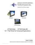
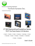
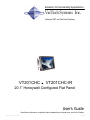
VT201CHC
.
VT201CHC-IR
20.1” Honeywell Configured Flat Panel
User’s Guide
Read these instructions completely before attempting to operate your new Color Display.
VT201CHC User Guide
150-060
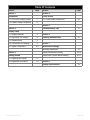
Table Of Contents
Section
Page
Section
Section 1
Section 4
Introduction
Touch screen
1.1 VT201CHC Display Family
1
1.2 Product Safety Precautions
2
4.1 Touch Screen Introduction
Page
10
Section 5
Section 2
Troubleshooting Tips
11
Display Setup
2.1 Display Features
3
Section 6
2.2 Unpacking The Display
4
Cleaning & Maintenance
2.3 Included Parts
4
2.4 Connecting Your Display
4
2.5 Signal Connections
4-5
12
Section 7
Mechanical Drawings
Mounting Instructions
13
Section 3
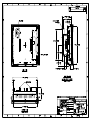
Display Mechanical Drawing
14-15
Getting Started
Display with Console Bezel Drawing
16-17
3.1 Adjusting the Display
6
3.2 Adjustment Procedure
7-9
Section 8
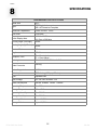
Display Specifications
VT201CHC User Guide
18
150-060
Section
1
1.1
INTRODUCTION
VT201CHC Display Family
The VT201CHC is part of a series of LCD replacement displays for the Honeywell "Z"
Style replacement furniture.
The VT201CHC display is an upgrade solution for US and UxS based systems. The
VT201CHC is compatible with EPDG, EPDG2, and TPDG video.
The VT201CHC-IR is a complete upgrade solution. The VT201CHC-IR is supplied with a
replacement console bezel and new flat IR touch frame which is compatible with the original
21” touch frame assembly being replaced.
1
VT201CHC User Guide
150-060
1.2
Product Safety Precautions
⇒
Ensure that sufficient space is available around the display to provide the circulation
necessary for cooling.
⇒
Ensure that the ambient air temperature will not exceed the specified maximum
temperature.
⇒
Do not attempt to service this display yourself. The rear chassis has a seal so that non
qualified personal will not expose themselves to dangerous voltages or other risks.
⇒
To protect from electrical shock, unplug the display power supply from the console before
moving.
⇒
Do not expose the display to excessive heat.
⇒
Do not use this display near water.
⇒
Unplug the power supply from the console or unit if one of the following conditions exists.
⇒ Power cord or plug is damaged or frayed
⇒ Liquid is spilled into the display or the display is exposed to rain or water.
⇒ The display does not operate normally when the operating instructions are
followed.
⇒ The display has been dropped or the enclosure has been damaged.
⇒ The display exhibits a distinct change in performance, indicating a need for
service.
2
VT201CHC User Guide
150-060
Section
DISPLAY SETUP
2
2.1 VT201CHC Display Features
⇒
Capable of displaying unlimited colors in a continuous spectrum. The high contrast LCD
enhances the image with no geometric distortion.
⇒
The VT201CHC comes with a HD15 Input Connector. The VT201CHC also includes an HD15
to DB9 Video Adapter Cable.
⇒
The VT201CHC is supplied with a remote membrane switch assembly that mounts to the front
of the console bezel for OSD controls.
⇒
The VT201CHC is supplied with an Anti-Reflective Screen.
⇒
The VT201CHC has an integrated 115/220VAC supply as standard.
3
VT201CHC User Guide
150-060
2.2 Unpacking and setting up your display
Your LCD monitor package will consist of the basic components listed below. Depending on the
display configuration, additional components are supplied.
2.3 What is included with your display
20.1” LCD Monitor
Video adapter cable (HD15 to DB9)
Accessory Kit: OSD Membrane Kit; Chassis Brackets; Power Cord; a HD15 to DB9 Video
Adapter Cable.
⇒ Users Guide (Printed or on CD)
⇒
⇒
⇒
2.4 Connecting the Display
1. Connect all cables to the station first. This would include the video adapter cable and the
original IR touch screen cable.
2. After connecting the cables between the LCD monitor and the station, plug the power cord
into the display.
3. Switch on the display power switch.
4. Reboot the station.
5. Your display should now operate showing the station video information.
Note: The displays are factory OSD adjusted for each configuration. However, additional OSD
adjustments may be required (See section 3).
2.5
Signal Connections
To avoid irregular operation and /or damage to the display, please insure correct video is being
supplied as shown on the following page.
4
VT201CHC User Guide
150-060
2.5
Signal Connections Cont.
Use the HD15 to DB9 video adapter cable to connect the flat panel display to the EPDG I/O
adapter board for EPDG and EPDG2 video. The HD15 to 5xBNC video adapter cable is supplied for non-standard configurations.
Note: The following figure is the view looking into the pin end of the male connector or solder
term end of the female connector.
HD15 Connector
The following table provides the pin numbers and corresponding
pin assignments for the HD-15 video connector.
Pin
Signal
1
Red Video
2
Green Video
3
Blue Video
4
Not Used
5
Not Used
6
Red Video Ground
7
Green Video Ground
8
Blue Video Ground
9
Not Used
10
Ground
11
Ground
12
Not Used
13
Horizontal Sync
14
Vertical Sync
15
Not Used
VT201CHC User Guide
HD15 Connector
Female
5
150-060
Section
GETTING STARTED
3
3.1
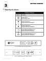
Adjusting the display
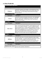
On Screen Display
Button
Description
Invokes OSD or
Next Function Level
Increase Contrast or
Increment Selected Parameter
Decrease Contrast or
Decrement Selected Parameter
Increase Backlight Brightness or
Increment Selected Parameter
Decrease Backlight Brightness or
Decrement Selected Parameter
For Use With VarTech Console Bezel
For Use With Honeywell Console Bezel
VT201CHC User Guide
6
150-060
3.3
User Controls
Direct Brightness Adjustment
OSD Agent
Description
Brightness
Controls the intensity of the backlight. After adjustment, the new
Brightness value is displayed on the screen until the OSD timeout
period expires. The new setting is then stored and the display
returns to normal.
Direct Contrast Adjustment
OSD Agent
Contrast
Description
Controls the contrast (video gain) of the picture. After adjustment,
the new contrast value is displayed on the screen until the OSD
timeout period expires. The new setting is then stored and the
display returns to normal.
Menu Select
OSD Agent
Description
Menu Select
Displays picture identification information together with a menu of
icons. To access lower-level functions, use the brightness up and
down or the contrast up and down buttons to toggle through the
menus available for the currently displayed signal type, then press
MENU again to select that function. The MENU button has a similar
function to the ENTER key on a computer keyboard. Exit from a
menu by selecting BACK which returns to the previous level.
When leaving the main menu you will be prompted to save any
changes, if you do not wish to save any changes select NO.
OSD Menu
OSD Agent
OSD Menu
Description
At the top of the menu is a line which identifies the type of signal
currently displayed. For computer signals the same section displays
the signal resolution, together with horizontal and vertical
frequencies. If its setup has been saved, the user number of the
signal is also displayed. (These figures are for guidance only).
Brightness and Contrast
OSD Agent
Brightness and Contrast
VT201CHC User Guide
Description
These perform the same functions as the direct brightness and direct
contrast button operations listed above.
7
150-060
3.3
Adjustment Procedure Cont.
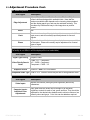
The Geometry Menu
OSD Agent
Edge Adjustment
Description
Adjusts Picture Size and Position Controls. The four “Edge”
controls shift each edge within available limits. Note that the
maximum available shift depends on the incoming video standard
and the display panel type, and may be restricted vertically. This
provides very flexible and easy to use image size an position
control.
Moire
N/A
Clock
Sets the total number of input pixels per line to correspond with the
input source, and will normally require adjustment for unusual
signals.
Phase
Adjusts the internal clock to sample each pixel as near as possible
to the centre. Phase will normally require adjustment for unusual
types of signal.
Input Select: Configures the preferred input selections.
(If a facility is not fitted, it will be displayed but not selectable.)
OSD Agent
Signal Type Priority
Video Priority Search
Order
Graphics Search
Description
Graphics-video
CVBS -Y/C - Component
Y/C - CVBS - Component
Component - CVBS - Y/C
RGB-DVI Note: DVI not available
Component Video Type RCB or YUV. Incorrect colors may be due to wrong selection here.
The Color Menu
OSD Agent
Description
Video Inputs
Adjusts the contrast (video gain) and brightness (black level)
parameters.
Computer InputsIndividual Color
Adjustments
VT201CHC User Guide
Red, green and blue levels can be thought of as individual
brightness controls for each of red, green and blue. They should be
adjusted for the desired color balance and to minimize noise on low
intensity colors and greys. Color tints can be added as required.
8
150-060
3.3
Adjustment Procedure Cont.
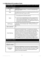
The System Menu: Contains functions which are more applicable to system operation
than to picture adjustment.
OSD Agent
Description
Esc
Returns to the last saved setup. It is useful if an adjustment has
been made in error.
Save
Saves all the user adjustments for the displayed signal type. The
new adjustments are stored in non-volatile memory and so are still
valid from a power down—power up cycle.
1) Restores the user adjustable parameters for the signal currently
being display back to the factory defaults.
Reset
OSD Timeout
OSD X and OSD Y
Auto Centering
2) Press the menu and brightness plus buttons simultaneously to
restore to factory default state all the user adjustments for the
signal currently being displayed. This is useful if a picture setup has become lost or confused. The Reset option can also be
accessed even if the OSD has been lost.
Controls the time after which the OSD display is cancelled. It can
be adjusted in 15-sec increments from 1 (=8 sec) to 4 (=90 sec)
approximately.
N/A
Yes/No. If an input signal changes, it is first measured and
compared with stored selections. If its parameters are already
stored, they are installed. If they are stored, the “Auto Centering”
selection is checked and if set to “No” the best fit is displayed. The
user can then center the picture using OSD auto setup. If Auto
Centering is set to “Yes”, centering is performed automatically,
which may take more than 15 seconds. This could cause a problem if using Windows, wherein a resolution change is displayed
only for 15 seconds and reverts to its previous selection if no
acknowledgement is entered. For this reason, the default state is
“No”. NOTE this control only configures Analog Graphics inputs.
The Miscellaneous Menu
OSD Agent
Image Flip Horizontal
Image Flip Vertical
Text Enhance /
Normal
VT201CHC User Guide
Description
N/A
N/A
Improves the appearance of fine text from a computer generated
analog input signal. Please note this function will only be effective if
the signal resolution is close to the resolution of the panel, no harm
will be done to the unit by trying the enhanced and normal text
options for other input resolutions.
9
150-060
Section
4
4.1
TOUCH SCREEN
Touch Screen Introduction
The VT201CHC-IR is supplied with a new flat IR touch frame which is compatible with the
original monitor IR touch frame.
Connect the DB9 cable connector of the original IR touch interface cable to the DB9
connector on the new IR touch frame.
It will be necessary to reboot the system for the new touch frame to be activated.
10
VT201CHC User Guide
150-060
Section
5
TROUBLESHOOTING
Troubleshooting Tips
Problem
Troubleshooting Tip
No image on display screen
1. Check that the power cord of the station has been connected to
the display.
2. Check that the power switch of the Display has been turned to
the on position.
3. Check that the Video (Signal) Cable from the Display has been
securely and correctly connected to the I/O adapter board.
4. Check that the Video Card and the I/O adapter card are firmly
seated in the card slots of the stations.
Abnormal image
1. Check that the correct display model is being used for the
station. VT181CHE for PDG, VT181CH for EPDG.
2. Check that the Video (Signal) Cable from the Display has been
securely and correctly connected to the connectors on the I/O
adapter board.
Colors of image on screen
are abnormal
1. Check that the Video (Signal) Cable from the display has been
securely and correctly connected to the I/O adapter board.
2. Adjust the OSD control for correct color balance.
Disturbances on Screen
1. OSD adjustment is incorrect. Please consult section 3 for OSD
screen adjustment procedures.
11
VT201CHC User Guide
150-060
Section
6
CLEANING AND MAINTANENCE
Cleaning
Occasionally clean the display panel and cabinet with a soft cloth dampened (not soaked) with a
mild (non-abrasive) glass cleaner. Keep turning a fresh side of the cloth toward the screen surface to
avoid scratching it with accumulated grit.
Note:
The solvent should be applied only to the cloth, and not directly on the monitor screen.
Do not use paper products as they may scratch the surface. To minimize the risk of abrasion, allow
the screen to stand dry.
Special care should be taken when cleaning a touch screen or polycarbonate shield that is installed
over the screen. Abrasive and certain chemical cleaners can easily damage the surface.
Never use alcoholic or ammoniac cleaners to clean the polycarbonate shield or a touch screen.
Note:
For best results cleaning a monitor with the optional antireflective tempered glass display shield, a
solution of denatured alcohol is recommended to thoroughly clean the display.
Other Maintenance
Qualified service personnel should perform all maintenance, except for the power cord replacement
described above.
VT201CHC User Guide
12
150-060
Section
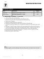
7
MOUNTING INSTRUCTIONS
Mechanical Drawings
Model
Description
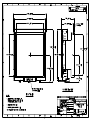
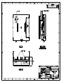
VT201CHC
Display only with original IR touch
14-15
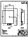
VT201CHC-IR
Display and replacement IR touch
16-17
7.1
Page(s)
Mounting Procedure - VT201CHC
1.
2.
3.
4.
5.
6.
7.
Remove the rear plastic console cabinet.
Disconnect the video cable, touch interface cable and power cord.
Remove the 4-6 screws that secure the display side mounting brackets.
Remove the CRT Display
Remove the original front plastic console bezel.
Install the new front replacement console bezel with the new IR touch frame.
Connect the membrane extension cable to the membrane tab that projects through the front console
bezel.
8. Mount the VT201CHC display and secure to the side mounting brackets with the provided screws.
9. Connect the membrane extension cable to the display where marked. Connect the video cable and
power cord to the display where marked. Set the display power switch to the ON position.
10. Connect the touch interface cable directly to the “D” connector on the new flat IR touch frame.
11. Make any OSD screen adjustments if required.
12. Install the rear plastic console cabinet.
Note:
For display upgrade only when replacing the flat screen Sony monitor, omit step 5, step 6, and step 7.
13
VT201CHC User Guide
150-060
14
TOUCH
OUTPUT
AC INPUT
100-220 VAC
50/60 Hz
0.75A
FAN TO HAVE 1.5"[38,1]
CLEAR AIR SPACE
CLEAN FILTER AS
REQUIRED
VGA
VIDEO
S
VIDEO
COMP
VIDEO
REMOTE
DISPLAY
CONTROLS
15
VarTech
Systems
16
TOUCH
OUTPUT
AC INPUT
100-220 VAC
50/60 Hz
0.75A
FAN TO HAVE 1.5"[38,1]
CLEAR AIR SPACE
CLEAN FILTER AS
REQUIRED
VGA
VIDEO
S
VIDEO
COMP
VIDEO
REMOTE
DISPLAY
CONTROLS
17
Section
8
SPECIFICATIONS
ENGINEERING SPECIFICATIONS
Panel Size
20.1”
Type
TFT Bright Active matrix
AR / AG Protective Faceplate
Resolution Capabilities
EPDG, EPDG2, TPDG
Pixel Pitch
0.3075mm
Active Display Area
16.21” x 12.20”
411.7mm x 309.8mm
Viewing Angle (Left/Right)
80/80º
Viewing Angle (Up/Down)
80/80º
Contrast Ratio
350:1
Brightness
250 Nits
Response Time
TR = 12ms typical
TF = 13ms typical
Back Lights
Cold Cathode 50,000 Hrs. Half Life
Video Connector
HD15(F)
Colors Supported
16.7M
Video Input
RGB Analog (0.7V p-p / 75ohm)
Sync
Separate H&V
Input Voltage
AC 100-240V 50/60Hz 1.0A
Power consumption
Normal: 55Watts DPMS: < 3Watts
Operating Temperature
0 to 50ºC
Storage Temperature
-20 to 60ºC
Operating Humidity
0 to 95%NC
Storage Humidity
0 to 95%NC
Operating Altitude
Up to 10,000 ft
Storage Altitude
Up to 40,000 ft
VT201CHC User Guide
18
150-060
VARTECH SYSTEMS
HEADQUARTERS
11529 Sun Belt Ct.
Baton Rouge, Louisiana 70809
Toll-Free: 800.223.8050
International Phone: 001.225.298.0300
Fax: 225.297.2440
E-mail: [email protected]
www.vartechsystems.com
150-060-001
12.28.04
VT201CHC User Guide
150-060