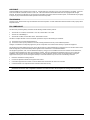
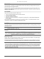
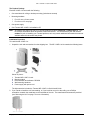
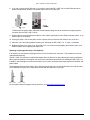
1
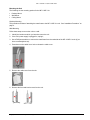
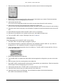
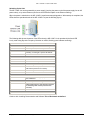
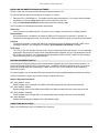
Part Number 69141
Tsunami MP.11 and MP.11a
Version 2.2
Quick Install Guide
COPYRIGHT
Copyright ©2005 Proxim Corporation, Sunnyvale, CA. All rights reserved. Covered by one or more of the following U.S. patents: 5,231,634;
5,875,179; 6,006,090; 5,809,060; 6,075,812; 5,077,753. This manual and the software described herein are copyrighted with all rights
reserved. No part of this publication may be reproduced, transmitted, transcribed, stored in a retrieval system, or translated into any language
in any form by any means without the written permission of Proxim Corporation.
TRADEMARKS
Tsunami, Proxim, and the Proxim logo are trademarks of Proxim Corporation. All other trademarks mentioned herein are the property of their
respective owners.
FCC COMPLIANCE
This document provides regulatory information for the following wireless outdoor products:
▪
▪
▪
Tsunami MP.11 2411 BSU, Tsunami MP.11 2411 SU, Tsunami MP.11 2411 RSU
Tsunami 2411 QuickBridge 11
Tsunami MP.11a BSU, Tsunami MP.11a SU, Tsunami MP.11a RSU
This device complies with Part 15 of the FCC Rules. Operation is subject to the following two conditions:
(1)
(2)
This device may not cause harmful interference
This device must accept any interference received, including interference that may cause undesired operation.
Changes or modifications not expressly approved by Proxim Corporation could void the user's authority to operate the equipment.
This equipment has been tested and found to comply with the limits for a Class B digital device, pursuant to Part 15 of the FCC Rules. These
limits are designed to provide reasonable protection against harmful interference in a residential installation.
This equipment generates, uses, and can radiate radio frequency energy and, if not installed and used in accordance with the instructions,
may cause harmful interference to radio communications. However, there is no guarantee that interference will not occur in a particular
installation. If this equipment does cause harmful interference to radio or television reception (which can be determined by turning the
equipment off and on), the user is encouraged to attempt to correct the interference by one or more of the following measures:
▪
▪
▪
▪
Reorient or relocate the receiving antenna.
Increase the separation between the equipment and receiver.
Connect the equipment into an outlet on a circuit different from that to which the receiver is connected.
Consult the dealer or an experienced radio or television technician for help.
This device must be professionally installed. Antennas used for the MP.11a product must be fix-mounted on
permanent structures with a separation distance of at least 2 meters from all persons during normal operation.
Copyright © 2004 Proxim Corporation. All rights reserved.
2
MP.11 and MP.11a Quick Install Guide
Introduction
The Tsunami MP.11 and MP.11a are flexible wireless outdoor routers that let you design solutions for point-topoint links and point-to-multipoint networks.
The Tsunami MP.11 and MP.11a product families comprise several products (such as the Tsunami MP.11 SU
and BSU). For simplification, all products that are part of the Tsunami MP.11 and MP.11a Product Families are
referred to as MP.11/MP.11a.
KEY FEATURES
Some of the key features of the MP.11/MP.11a are:
▪
▪
▪
▪
The use of a highly optimized protocol for outdoor situations
Routing and bridging capability
Asymmetric bandwidth management
Management through a Web Interface, a Command Line Interface (CLI), or Simple Network Management
Protocol (SNMP)
This document shows the basics of setting up the Tsunami MP.11/MP.11a. For detailed information, see the
Tsunami MP.11 and MP.11a Installation and Management Guide.
Installation
This chapter describes the steps required to install and mount the MP.11/MP.11a, including installing, mounting,
and aligning the radio.
Note:
The installation does not cover the mounting and connection of antennas. See the applicable Antenna
Installation Guide (MP.11 or MP.11a).
If you are already familiar with this type of product, you can use the Quick Install Guide for streamlined installation
procedures.
IMPORTANT!
Before installing this product, see Appendix C of the Installation and Management manual for important
regulatory compliance, safety, and telecom certification information.
INSTALLING THE UNIT
The MP.11/MP.11a supports two power methods⎯an AC power outlet and Active Ethernet. The power supply
accepts an input AC voltage in the range of 100-240 VAC.
The following installation procedure provides instructions for attaching both the power and Ethernet connectors.
In situations without an external antenna (for example, during a desk tryout), the antenna cable is not required.
WARNING!
For your own safety, use only the power cord supplied with the unit. The metal case of the unit must be
grounded through the ground connection that is provided on the metal case. The antenna grounding,
the surge arrestor, and the MP.11/MP.11a unit housing must be bonded together and grounded in one
location to avoid ground current loops.
Copyright © 2004 Proxim Corporation. All rights reserved.
3
MP.11 and MP.11a Quick Install Guide
The Product Package
Each MP.11/MP.11a comes with the following:
▪
One metal base for ceiling or desktop mounting (includes two screws)
▪
Mounting hardware
º
º
Four 3.5 mm x 40 mm screws
Four 6 mm x 35 mm plugs
▪
One power supply
▪
One Tsunami MP.11/MP.11a Installation CD
Note:
All software CDs that come with your Tsunami products include a readme.txt or readme.html file. This
file contains information about the software version and drivers. You are advised to print and read the
readme file prior to installing your Tsunami products, as it may contain additional information that was not
available when this document was printed.
Installation Procedure
To install the MP.11/MP.11a:
1. Unpack the unit and accessories from the shipping box. The MP.11/MP.11a kit contains the following items:
Shown in picture:
1
2
3
4
5
Tsunami MP.11/MP.11a unit
Mounting stand
Documentation and software CD-ROM
Wall mounting hardware
Power supply with power cord
The shipment also includes the Tsunami MP.11/MP.11a Quick Install Guide.
2. If you intend to install the unit free-standing, or if you intend to mount it to the ceiling, use a Phillips
screwdriver to attach the metal base to the underside of the unit. The metal base and screws are provided
(see “Mounting the Unit” on page 7 for more information).
Copyright © 2005 Proxim Corporation. All rights reserved.
4
MP.11 and MP.11a Quick Install Guide
3. Unlock the unit’s cable cover. To release the cable cover, press down on the cable cover lock located in the
front center of the unit.
4. Remove the cable cover.
5. Remove the front cover from the unit (the side with the LED indicators, shown in the figure on left); then
remove the back cover (figure on right).
6. Connect the grounding wire to the MP.11/MP.11a using the Faston plug on the metal case, next to the power
plug.
7. Connect one end of an Ethernet cable (not supplied) to the Ethernet port. The other end of the cable should
not be connected to another device until after installation is complete.
º
Use a straight-through Ethernet cable if you intend to connect the MP.11/MP.11a to a hub, switch, patch
panel, or Active Ethernet power injector.
º
Use a cross-over Ethernet cable if you intend to connect the MP.11/MP.11a to a single computer.
Copyright © 2005 Proxim Corporation. All rights reserved.
5
MP.11 and MP.11a Quick Install Guide
8. If you are not using Active Ethernet, or you want to connect the MP.11/MP.11a to Active Ethernet and AC
power simultaneously, attach the AC power cable to the unit’s power port.
To disconnect the power cable, slide back the black plastic fitting around the connector and gently pull the
connector from the MP.11/MP.11a unit.
9. Connect the free end of the Ethernet cable to a hub, switch, patch panel, Active Ethernet power injector, or an
Ethernet port on a computer.
10. If using AC power, connect the power cord to a power source (such as a wall outlet) to turn on the unit.
11. Place the unit in the final installation location (see “Mounting the MP.11/MP.11a” on page 7 for details).
12. Replace the back cover, front cover, and cable cover. Be careful to avoid trapping the antenna, power, and
Ethernet cables when replacing the cable cover.
Attaching a Kensington Security Lock (Optional)
If so desired, you can attach a Kensington lock to secure the cable cover into place. This protects the unit from
unauthorized tampering.
The MP.11/MP.11a enclosure includes a Kensington Security Slot for use with a Kensington locking mechanism.
When properly installed, a Kensington lock can prevent unauthorized personnel from stealing the MP.11/MP.11a.
In addition, the Kensington lock secures the cable cover in place, which prevents tampering with the Ethernet and
power cables.
The Kensington Security Slot is shown in the following figures (the figure on the left shows the slot with the cable
cover attached; the figure on the right shows the slot with the cable cover removed).
For information about Kensington security solutions, go to http://www.kensington.com .
Copyright © 2005 Proxim Corporation. All rights reserved.
6
MP.11 and MP.11a Quick Install Guide
Mounting the Unit
The following are the mounting options for the MP.11/MP.11a:
▪
▪
▪
Desktop Mount
Wall Mount
Ceiling Mount
Desktop Mounting
This procedure consists of attaching the metal base to the MP.11/MP.11a unit. See “Installation Procedure” on
page 4.
Wall Mounting
Follow these steps to mount the unit on a wall:
1. Identify the location at which you intend to mount the unit.
2. If the unit’s power supply is plugged in, unplug it,
3. Use a Phillips screwdriver to remove the metal base from the underside of the MP.11/MP.11a unit (if you
have not already done so).
4. Press down on the cable cover lock to release the cable cover .
5. Remove the cable cover from the unit.
6. Remove the front and back covers from the unit.
Copyright © 2005 Proxim Corporation. All rights reserved.
7
MP.11 and MP.11a Quick Install Guide
7. Place the back cover on the mounting location and mark the center of the three mounting holes.
8. Remove the cover from the wall and drill a hole at each of the locations you marked. Each hole should be
wide enough to hold a mounting plug (6 mm x 35 mm).
9. Insert a plug into each hole.
(Four 6 mm x 35 mm plugs are provided; you need to use only three of these for wall mounting.)
10. Insert a screw into each of the mounting holes molded into the back cover.
(Four 3.5 mm x 40 mm pan-head screws are provided; you need to use only three of these for wall mounting.)
11. Insert the screws into the wall plugs; use a screwdriver to tighten the screws and attach the back cover to the
wall.
12. Attach Ethernet and power cables to the MP.11/MP.11a unit, as necessary.
13. Snap the unit into the back cover, replace the front cover, and replace the cable cover.
14. Turn on the MP.11/MP.11a (see “Switching On the Unit” on page 9).
Ceiling Mounting
Follow these steps to mount the MP.11/MP.11a to a ceiling:
1. If the MP.11/MP.11a’s power supply is plugged in, unplug it.
2. Use a Phillips screwdriver to attach the metal base to the underside of the MP.11/MP.11a, if you have not
already done so. See “Installation Procedure” on page 4 for an illustration.
3. Feed a mounting screw through each of the four rubber feet. The MP.11/MP.11a comes with four 3.5 mm x
40 mm pan-head screws.
4. Remove the screws from the rubber feet.
5. Turn the MP.11/MP.11a upside down and position the base against the ceiling where you want to mount the
unit.
6. Mark the center of the four mounting holes in the rubber feet.
7. Set the MP.11/MP.11a aside and drill a hole at each of the locations you marked above. Each hole should be
wide enough to hold a mounting plug (6 mm x 35 mm).
8. Insert a plug into each hole. The MP.11/MP.11a comes with four 6 mm x 35 mm plugs.
9. Insert the screws into the holes you made previously in the rubber feet.
10. Insert the screws into the mounting plugs. Use a screwdriver to tighten the screws and attach the
MP.11/MP.11a’s metal base to the ceiling.
Copyright © 2005 Proxim Corporation. All rights reserved.
8
MP.11 and MP.11a Quick Install Guide
Switching On the Unit
The MP.11/MP.11a can be powered by a power supply (just plug the power cord of the power supply into an AC
power outlet), or by Active Ethernet (connect an Active Ethernet splitter to the Ethernet cabling).
When the power is switched on, the MP.11/MP.11a performs startup diagnostics. When startup is completed, the
LEDs show the operational state of the MP.11/MP.11a (see the following figure).
The following table shows the status of the LEDs when the MP.11/MP.11a is operational (the fourth LED
is only used during Dynamic Frequency Selection on a BSU; flashing green indicates scanning).
Power
OFF
Power is not present or is malfunctioning.
GREEN
Power is present; the unit is operational.
AMBER
The unit is initializing after reboot (less than two
minutes); it cannot get a dynamic IP address.
RED
A fatal error in the unit.
Ethernet Link
OFF
Not connected.
GREEN
Connected at 10 Mbps.
BLINKING GREEN
Data is being sent at 10 Mbps.
AMBER
Connected at 100 Mbps, or the unit is initializing
after reboot (less than two minutes).
BLINKING AMBER
Data is being sent at 100 Mbps.
RED
An error in data transfer.
Wireless Link
OFF
Wireless interface is up properly but no wireless
link established.
GREEN
Immediately after connecting a wireless link.
BLINKING GREEN
Data is being sent or the wireless interface
is initializing after reboot (less than two
minutes).
RED
There is a fatal error on the wireless interface.
* See “Forced Reload” Error! Bookmark not defined..
Continue with “Installing Documentation and Software” Error! Bookmark not defined..
Copyright © 2005 Proxim Corporation. All rights reserved.
9
MP.11 and MP.11a Quick Install Guide
INSTALLING DOCUMENTATION AND SOFTWARE
The MP.11/MP.11a also comes with documentation and software on a CD.
To install the documentation and software on a computer or network:
1. Place the CD in a CD-ROM drive. The installer normally starts automatically. You can also start the installer
manually by running the setup.exe program in the root directory of the CD.
2. Click the Install Help and Software button and perform the necessary steps.
The CD contains the following documentation and software:
Online help
This is the help for the Web Interface. It is stored on your computer or network so it is always available.
Documentation
Documentation also is available in an electronic (PDF) form, including the Tsunami MP.11 and MP.11a
Installation and Management Guide, Tsunami MP.11 Antenna Installation Guide, and this Quick Install Guide.
ScanTool
The ScanTool program is a utility with which you can obtain or set the IP address of the MP.11/MP.11a for
management access. See “Setting the IP Address” Error! Bookmark not defined. for details.
TFTP Server
The TFTP (Trivial File Transfer Protocol) server lets you transfer files across the network. You can download
configuration files, as well as image files for embedded software upgrades, and you can upload files from the
MP.11/MP.11a for backup. Here downloading means transferring files to the MP.11/MP.11a and uploading
means transferring files in the opposite direction.
ANTENNA ALIGNMENT DISPLAY
Antenna Alignment Display (AAD) provides a measurement of signal quality in an easy-to-interpret manner—a
numeric printed signal value at the CLI and serial ports. The SNR is numerically displayed on the CLI or serial
port by two decimal characters representing a number from 00 to 99. On the serial port, AAD is enabled by
default after booting.
To start the display, you must enable AAD and a wireless link must be established between the BSU and the SU.
Aiming is complete if moving in any direction results in a falling SNR value.
Antenna Alignment Commands
set aad enable local
Enables display of the local SNR. Local SNR is the SNR measured by the receiver at the near end.
set aad enable remote
Enables display of the remote SNR. Remote SNR is the SNR as measured by the receiver at the far end.
set aad enable average
Enables display of the average SNR. The average SNR is the average of the local and remote SNR.
set aad disable
Disables Antenna Alignment Display (Ctrl-C also disables AAD).
COMPLETING INSTALLATION
Make sure the waterproof cap is re-installed on the serial port.
Copyright © 2005 Proxim Corporation. All rights reserved.
10
MP.11 and MP.11a Quick Install Guide
ACCESSING THE WEB BROWSER
To access the MP.11/MP.11a with a Web browser:
1. Start a Web browser (such as Internet Explorer) and enter the MP.11/MP.11a’s IP address (for example,
http://10.0.0.1).
2. A login window is displayed. Do not fill in the User name; enter only the default password public.
If your MP.11/MP.11a is configured to obtain an IP address dynamically:
1. Install ScanTool, located on the Tsunami MP.11/MP.11a CD-ROM.
The MP.11/MP.11a must be on the same subnet as the PC on which ScanTool is installed; if necessary,
change the PC’s IP settings.
2. To find the IP address of the MP.11/MP.11a, run ScanTool by clicking Start Æ Programs Æ Proxim Æ
ScanTool.
Once you have learned the IP address of the MP.11/MP.11a you want to manage, enter that address in your Web
browser address field.
ACCESSING THE COMMAND LINE INTERFACE
The CLI is accessible through the Ethernet port connected through the network, or with a cross-over Ethernet
cable between the computer and the serial port of the MP.11/MP.11a.
Ethernet Port
To use the CLI through the Ethernet port, you must have a telnet program and know the IP address of the
MP.11/MP.11a.
To access the MP.11/MP.11a through Ethernet:
1. From the Windows Start menu, select Run; enter cmd.
2. In the DOS window displayed, enter the IP address (for example, telnet 10.0.0.1).
3. Click OK to start the telnet program; you are prompted for your password.
4. Enter the password (the default password is public).
Serial Port
In some cases, it may not be possible to retrieve the IP address of the MP.11/MP.11a. In this case, you can use
a serial cable to access the device.
Note:
Proxim recommends you switch off the MP.11/MP.11a and the computer before connecting or
disconnecting the serial cable.
To access the MP.11/MP.11a through the serial port:
1. Start your terminal program.
2. Set the following connection properties; then connect:
COM port:
Bits per second:
Data bits:
Stop bit:
Flow control:
Parity:
Line ends:
such as COM1 or COM2, to which the MP.11 serial port is connected
9600
8
1
none
none
carriage return with line feed
Copyright © 2005 Proxim Corporation. All rights reserved.
11
MP.11 and MP.11a Quick Install Guide
3. Press the RESET button on the indoor MP.11/MP.11a unit. After approximately 90 seconds you are
prompted for your password.
RESET
RELOAD
4. Enter the default password public.
Management
To view or change basic system information, click the Configure button on the left side of the Web interface
window, then click the System tab.
SELECTING A COUNTRY
The Tsunami MP.11/MP.11a provides a selectable Country field that automatically provides the allowed band
and frequencies for the selected country as well as, where applicable, Dynamic Frequency Selection (DFS) and
Transmit Power Control (TPC). A country selection with DFS enabled causes the MP.11a Base Station to come
up in scan mode. It scans the available frequencies and channels to avoid radar and select a channel with the
strongest signal.
By default, the Tsunami MP.11/MP.11a lets you transmit at the maximum output power for the country or
regulatory domain and frequency selected. However, with Transmit Power Control (TPC), you can adjust the
output power of the unit to a lower level in order to reduce interference from neighboring devices or to use a
higher gain antenna without violating the maximum radiated output power allowed for your country
MP.11/MP.11a kits sold in the United States are pre-configured to scan and display only the outdoor frequencies
permitted by the FCC. No other Country selections, channels, or frequencies may be configured.
MP.11/MP.11a kits sold outside of the United States and Canada support the selection of a Country by the
professional installer. Click the Configure button and the System tab; then select the appropriate country for your
regulatory domain.
Continue configuring settings as desired; then click the Commands button and the Reboot tab to save and
activate the settings.
CHANGING THE IP CONFIGURATION
To change the IP Configuration, click the Configure button and the Network tab; then click the IP Configuration
tab.
CONFIGURING INTERFACES
To configure the Ethernet and Wireless interfaces, click the Configure button and the Interfaces tab.
Copyright © 2005 Proxim Corporation. All rights reserved.
12
MP.11 and MP.11a Quick Install Guide
CHANGING THE SECURITY SETTINGS
Proxim highly recommends you change the Network Name and Shared Secret as soon as possible. To do so,
click the Configure button and the Interfaces tab; then click the Wireless sub-tab.
To change the passwords of the MP.11/MP.11a, click the Configure button, then the Telnet, HTTP, or SNMP
tab.
UPGRADING EMBEDDED SOFTWARE
The MP.11/MP.11a is equipped with embedded software. Updates of this software can be found on the Proxim
Internet site.
Not all software releases support all products in the Tsunami MP.11/MP.11a family. Proxim recommends that
you always refer to the Release Notes to determine whether the version of software to which you want to upgrade
is supported on your MP.11/MP.11a product.
To download files to the MP.11/MP.11a, click the Commands button and select the Download tab.
APPLYING CHANGES
To apply your changes to the MP.11/MP.11a, reboot the device. If you do not want to reboot immediately, issue
the CLI save command to ensure your changes are saved. When you do reboot, the MP.11/MP.11a is restarted
with the new settings.
In the Web interface, click the Commands button and the Reboot tab to issue the reboot command.
DEFAULT SETTINGS
The default settings for the MP.11/MP.11a are:
Must be set by the professional installer
Disabled
Full (-0dBm)
DHCP enabled or 10.0.0.1
DHCP enabled or
255.255.255.0
HTTP password:
public
Telnet password:
public
SNMP Read password:
public
SNMP Read/Write password:
public
Country:
DFS:
TPC:
IP address:
Subnet mask:
Copyright © 2005 Proxim Corporation. All rights reserved.
13
MP.11 and MP.11a Quick Install Guide
Support and Contacts
If you are having a problem using a Proxim WAN product and cannot resolve it with the information in the product
documentation, gather the following information and contact Proxim Technical Support:
▪
▪
▪
▪
What kind of network are you using?
What were you doing when the error occurred?
What error message did you see?
Can you reproduce the problem?
Be sure to obtain an RMA number before sending any equipment to Proxim for repair.
To receive E-mail technical support, please be sure to include the serial number of the product(s) in question. The
serial number should be on the product and conform to the following format: ##UT######## or ##R7########.
We will be unable to respond to your inquiry without this information.
USA & Canada Customers
Call Technical Support: WAN Toll Free
866-674-6626 or
408-542-5390
Hours: 6:00 AM to 5:00 PM M-F Pacific Time
LAN Toll Free
866-674-6626 Hours: 24x7
International Customers
Call Technical Support:
WAN 408-542-5390 Hours: 6:00 AM to 5:00 PM M-F Pacific Time
LAN 408-542-5390 Hours: 24x7
Latest software and documentation: http://support.proxim.com/
Search Knowledgebase:
http://support.proxim.com/
Copyright © 2005 Proxim Corporation. All rights reserved.
14