1
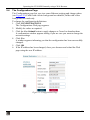
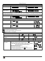
Kramer Protocol
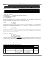
2nd byte
OUTPUT
1
O6
O5
O4
O3
O2
O1
O0
7
6
5
4
3
2
1
0
1
OVR
X
M4
M3
M2
M1
M0
7
6
5
4
3
2
1
0
3rd byte
MACHINE NUMBER
4th byte
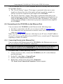
1st BYTE:
Bit 7 – Defined as 0.
D – “DESTINATION”:
0 - for sending information to the switchers (from the PC);
1 - for sending to the PC (from the switcher).
N5…N0 – “INSTRUCTION”
The function that is to be performed by the switcher(s) is defined by the INSTRUCTION (6 bits). Similarly, if a function is performed
via the machine’s keyboard, then these bits are set with the INSTRUCTION NO., which was performed. The instruction codes are
defined according to the table below (INSTRUCTION NO. is the value to be set for N5…N0).
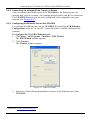
Bit 7 – Defined as 1.
2nd BYTE:
I6…I0 – “INPUT”.
When switching (ie. instruction codes 1 and 2), the INPUT (7 bits) is set as the input number which is to be switched. Similarly, if
switching is done via the machine’s front-panel, then these bits are set with the INPUT NUMBER which was switched. For other
operations, these bits are defined according to the table.
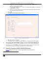
Bit 7 – Defined as 1.
3rd BYTE:
O6…O0 – “OUTPUT”.
When switching (ie. instruction codes 1 and 2), the OUTPUT (7 bits) is set as the output number which is to be switched. Similarly, if
switching is done via the machine’s front-panel, then these bits are set with the OUTPUT NUMBER which was switched. For other
operations, these bits are defined according to the table.
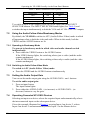
4th BYTE:
Bit 7 – Defined as 1.
Bit 5 – Don’t care.
OVR – Machine number override.
M4…M0 – MACHINE NUMBER.
Used to address machines in a system via their machine numbers. When several machines are controlled from a single serial port, they
are usually configured together with each machine having an individual machine number. If the OVR bit is set, then all machine
numbers will accept (implement) the command, and the addressed machine will reply.
For a single machine controlled via the serial port, always set M4…M0 = 1, and make sure that the machine itself is configured as
MACHINE NUMBER = 1.
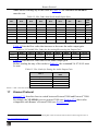
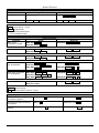
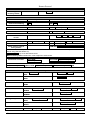
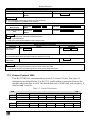
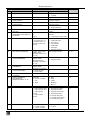
Table 18: Instruction Codes for Protocol 2000
Note: All values in the table are decimal, unless otherwise stated.
#
INSTRUCTION
DESCRIPTION
DEFINITION FOR SPECIFIC INSTRUCTION
INPUT
OUTPUT
NOTE
0
RESET VIDEO
0
0
1
1
SWITCH VIDEO
Set equal to video input
which is to be switched
(0 = disconnect)
Set equal to video output which
is to be switched
(0 = to all the outputs)
2
2
SWITCH AUDIO
Set equal to audio input
which is to be switched
(0 = disconnect)
Set equal to audio output
which is to be switched
(0 = to all the outputs)
2
42
KRAMER: SIMPLE CREATIVE TECHNOLOGY