1
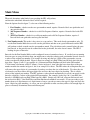
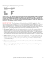
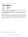
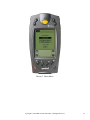
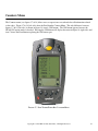
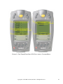
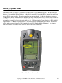
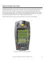
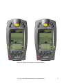
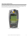
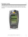
US AUTOMATION EP-1
BARCODE SCANNER
USER MANUAL
Table of Contents
Table of Contents.............................................................................................................................................. 2
Table of Figures ............................................................................................................................................... 3
Introduction ...................................................................................................................................................... 4
Getting Started.................................................................................................................................................. 4
TRG3000 Trigger Handle................................................................................................................................. 7
Installation/Setup of the EP1............................................................................................................................ 7
Options Button .............................................................................................................................................. 9
Mode Selection............................................................................................................................................ 10
Mode Menu ................................................................................................................................................. 11
Scanning 1-D Bar Codes with the EP1 ....................................................................................................... 16
Scanning PDF417 (2-D) Bar Codes with the EP1 ...................................................................................... 17
Pick Ticket Setup ........................................................................................................................................ 18
Pick Ticket Setup Menu .............................................................................................................................. 19
Parts Bin Setup ............................................................................................................................................ 20
Parts Bin Setup Menu.................................................................................................................................. 21
Counters Selection....................................................................................................................................... 22
Counters Menu ............................................................................................................................................ 23
Counter Explanations ..................................................................................................................................... 24
What Happens When an Operator Encounters an Error? ............................................................................. 27
History Options Menu .................................................................................................................................... 28
JSN History Menu........................................................................................................................................... 29
JSN History Display ....................................................................................................................................... 30
Alerts Options Menu....................................................................................................................................... 31
Alerts Menu................................................................................................................................................. 32
Edit Part Number Alert Menu ..................................................................................................................... 33
Alerts Setup Completed Menu .................................................................................................................... 35
Part Number Alert Box ............................................................................................................................... 36
Is Your EP1 Scanner Ready to Use? .............................................................................................................. 37
Scanning Barcodes for the First Time............................................................................................................ 37
Troubleshooting.............................................................................................................................................. 38
Index ............................................................................................................................................................... 41
Copyright © 1999-2002 US Automation Inc., All Rights Reserved.
2
Table of Figures
FIGURE 1. OVERVIEW OF YOUR NEW EP1................................................................................................................ 5
FIGURE 2. HOW TO CHARGE YOUR EP1. .................................................................................................................. 6
FIGURE 3. EP1 TRG3000 TRIGGER HANDLE.......................................................................................................... 7
FIGURE 4. EP1 APPLICATION STARTUP ................................................................................................................... 8
FIGURE 5. OPTIONS MENU ...................................................................................................................................... 9
FIGURE 6. MODE SELECTION................................................................................................................................. 10
FIGURE 7. MODE MENU ........................................................................................................................................ 14
FIGURE 8. PART # PICK TICKET BARCODE EXAMPLE ............................................................................................ 15
FIGURE 9. PART # PARTS BIN BARCODE EXAMPLE ............................................................................................... 15
FIGURE 10. HOW TO SCAN A 1-D BARCODE LABEL. ............................................................................................. 16
FIGURE 11. HOW TO SCAN A 2-D BARCODE LABEL. ............................................................................................. 17
FIGURE 12. PICK TICKET SETUP ............................................................................................................................ 18
FIGURE 13. PICK TICKET SETUP MENU ................................................................................................................. 19
FIGURE 14. PARTS BIN SETUP ............................................................................................................................... 20
FIGURE 15. PARTS BIN SETUP MENU .................................................................................................................... 21
FIGURE 16. COUNTERS SELECTION ....................................................................................................................... 22
FIGURE 17. PICK TICKET/PARTS BIN COUNTER MENU.......................................................................................... 23
FIGURE 18. PICK TICKET/PARTS BIN & JSN (DUAL OPTION) COUNTER MENUS................................................... 26
FIGURE 19. HISTORY OPTIONS MENU ................................................................................................................... 28
FIGURE 20. JSN HISTORY MENU .......................................................................................................................... 29
FIGURE 21. JSN HISTORY DISPLAY ...................................................................................................................... 30
FIGURE 22. ALERTS OPTIONS MENU ..................................................................................................................... 31
FIGURE 23. ALERTS MENU .................................................................................................................................... 32
FIGURE 24. EDIT PART NUMBER ALERT MENU ..................................................................................................... 33
FIGURE 25. KEYBOARD NUMBERS AND LETTERS MENUS ..................................................................................... 34
FIGURE 26. ALERTS SETUP COMPLETED MENU .................................................................................................... 35
FIGURE 27. PART NUMBER ALERT BOX ................................................................................................................ 36
Copyright © 1999-2002 US Automation Inc., All Rights Reserved.
3
Introduction
Congratulations on your purchase of the US Automation EP1 Barcode Scanner. This manual refers to your new
scanner as the EP1, which is based on Symbol’s SPT 1700 Series scanner with an integrated Palm OS
computer. This guide covers the installation/setup of the barcode scanner. All units are tested prior to being
shipped and can be used upon arrival; however, it is recommended that you read this manual before operating
the EP1 unit.
Getting Started
Before the US Automation EP1 scanner can begin error proofing at a job operation, you will need to do the
following:
1.) You should become familiar with:
A. All the different parts of your EP1 (see figure 1).
B. How to charge the battery on your EP1 (see figure 2). The unit must be fully charged before
beginning usage of it.
C. Using the trigger handle (if purchased).
2.) With the unit fully charged select and set a mode of operation for the EP1 (see page 8).
3.) Request new barcode labels be printed out at the operation where you want error proofing to be performed.
The new barcode label printed must match the mode that you have selected in step 2) above. This request is
made to your local IT or Flex printer support person. The EP1 works with all standard GM/EDS printers.
4.) When step 3) is complete and new barcode labels are being printed out at the operation, then you are ready
to run the “Pick ticket setup” and the “Parts bin setup” (see page 20).
Copyright © 1999-2002 US Automation Inc., All Rights Reserved.
4
FIGURE 1. OVERVIEW OF YOUR NEW EP1
Copyright © 1999-2002 US Automation Inc., All Rights Reserved.
5
FIGURE 2. HOW TO CHARGE YOUR EP1.
Copyright © 1999-2002 US Automation Inc., All Rights Reserved.
6
TRG3000 Trigger Handle
The TRG3000 Trigger Handle adds a pistol grip with a trigger to your EP1, increasing ergonomic comfort when
using the terminal in scan-intensive applications for extended periods of time.
To insert the EP1 into the trigger handle:
1. Slide the EP1 into the trigger handle until it locks into place (see figure 3).
To Remove the EP1 from the trigger handle:
2. To remove the EP1, press down the release spring and pull the EP1 forward (see figure 3).
FIGURE 3. EP1 TRG3000 TRIGGER HANDLE.
Installation/Setup of the EP1
Before using your new EP1 you must scan a sample of each of the barcodes that will be used in your
application. The EP1 will then build a rules set and know how to properly check the barcodes. In other words
by showing samples of the barcodes that you will be using at your operation to the EP1 while it is in setup
mode, you will be able teach your EP1 which type of barcodes to use when performing error proofing checks.
Start by getting samples of the barcodes that will be scanned.
The mode selected will determine how many and of which type of barcodes you need to scan.
1. Part Number mode – 2-barcode labels required (one pick ticket barcode and one parts bin label barcode).
2. Job Sequence Number mode – 1 Job Sequence Number barcode label required.
3. JSN/ Part Number mode – 2-barcode labels required (one pick ticket barcode and one parts bin label
barcode).
Copyright © 1999-2002 US Automation Inc., All Rights Reserved.
7
From the main desktop, start up the EP1 application (see figure 4, item 1).
Note: Your EP1 application may not be in the same location as the picture below, but the icon will look the
same.
FIGURE 4. EP1 APPLICATION STARTUP
Copyright © 1999-2002 US Automation Inc., All Rights Reserved.
8
Options Button
Then press the options button (Menu Icon) figure 5, item 1 shown below.
FIGURE 5. OPTIONS MENU
Copyright © 1999-2002 US Automation Inc., All Rights Reserved.
9
Mode Selection
From the Options listed, select Mode (figure 6, item 1 shown below).
FIGURE 6. MODE SELECTION
Copyright © 1999-2002 US Automation Inc., All Rights Reserved.
10
Mode Menu
The mode determines what kind of error proofing the EP1 will perform,
and therefore what kind of barcode labels will be required.
From the Options listed in figure 7, select one of the following modes:
1. Part Number – checks to make sure part numbers match, requires 2 barcode labels one pick ticket and
one parts bin label.
2. Job Sequence Number – checks for a valid Job Sequence Number, requires 1 barcode label with JSN
only.
3. JSN/ Part Number – checks for a valid part number and valid Job Sequence Number, requires 2
barcode labels one pick ticket and one parts bin label.
1.) Part Number mode: This mode is the easiest to set up and use. This mode checks part numbers only. To
use the Part Number Mode the user will scan the pick ticket and then scan a parts bin barcode and the EP1
will perform a check to make sure the part numbers match. The pick ticket can be scanned before the parts
bin barcode, or the parts bin can be scanned before the pick ticket, the order doesn’t matter. The EP1 is
looking for pairs of barcodes.
Barcodes for the Part Number Mode can be configured in any of a number of ways. If you find you are running
short on space on your pick tickets then you might want to consider reducing your part number barcode down to
a subset of the original part number. For example by using only the last 4 digits of the part number you can
reduce your barcode length by half. Figure 8 shows an example of a Pick Ticket barcode label where this has
been done. Figure 9, item 1 is an example of a 2-dimensional Parts Bin Barcode label in the GM standard
1724A format (also known as PD417 format). Notice in figure 9, item 2 that the lower four-digits of the part
number matches the number in figure 8; this is an example of a subset. The EP1 makes the assumption that you
will remove the upper digits of a part number if you have to reduce the size of the barcode. To reduce the size
of a barcode you must remove the upper digits first and leave the lower digits for checking. This is called a
subset of the original part number. The EP1 performs a subset check automatically for you if you supply it with
barcodes, which are a subset of the original full part number. For example, look at fig 8 & 9, your Parts bin
barcode is 10310099 and your Pick Ticket barcode is 0099. Simply strip 1031 off your parts bin barcode and
the end result is 0099. Your Pick Ticket and Parts Bin barcode numbers now match. So you can reduce a part
number from an 8-digit format to a 4-digit format as long as you always remove the upper 4 digits and leave the
lower 4 digits for parts matching. As a user you are responsible to make sure that you have left enough digits in
place to accurately discriminate between different parts.
Copyright © 1999-2002 US Automation Inc., All Rights Reserved.
11
The following are valid barcode formats for part numbers.
Parts Bin
10020099
10020099
0099
0099
10020099
10020099
Pick Ticket
10020099
0099
10020099
0099
20099
099
As long as there is some difference between the pick ticket and parts bin barcode format, the EP1 can determine
if the user has made mistakes like scanning 2 pick tickets in a row, or scanning 2 parts bins in a row, and will
report any such deviation as an error. In the example shown above there are two differences between the parts
bin and pick ticket barcode. One difference is that the length of the part number is not the same, and the other is
that one uses a 1D format and the other a 2D format.
IMPORTANT NOTE: When choosing parts bin barcodes, the parts bin label can be either a label
directly on the part from the supplier, or it can be the label on the parts bin itself. But once a barcode is
chosen for error proofing, then the operator must stick with that barcode unless a decision is made to
change which barcode to scan. If a decision is made to change the parts bin barcode, then the “Parts bin
setup” on page 20 would have to be performed again while scanning the proper barcode label.
2.) Job Sequence Number: These labels will contain numbers that are in order. It is recommended that this
mode be used mainly to double-check your work. An example would be to use the part number mode at
station 1 to check the parts loaded onto a rack. When the rack arrives at station 2, a second scanner would
be used to check each part for the correct Job Sequence Numbers (JSN) before shipping. A typical label
will resemble figure 8 and each number scanned after the first should be in sequence or an alarm will sound.
3.) JSN/Part Number: This mode generates the most thorough checking. A pick ticket will have both a job
sequence number and part number so two checks are performed at once. A pick ticket barcode label will
contain a dot (a period) separating the job sequence number and part number (ex. 1234567.12345678)
( JSN.PARTNUMBER).
4.) Each scan will then check for a part number that is different (unless you have checked the Dual JSN box)
and a correct sequence number.
When you request a pick ticket barcode be printed for this mode you must request the following format:
Job Sequence Number. Part Number
Copyright © 1999-2002 US Automation Inc., All Rights Reserved.
12
The following are valid barcode formats for JSN / Part number mode.
Parts Bin
10020099
10020099
0099
0099
10020099
10020099
Pick Ticket
10003001.10020099
3001.0099
10003001.10020099
10003001.0099
10003001.20099
03001.099
NOTE: It is required that you use at least 5 digits for the JSN portion of the barcode which would be
99999 jobs before a roll over of job sequence numbers occurs.
NOTE: When using the JSN mode or the JSN/Part number, remember that there will be a JSN Error on
your first scan because no previous numbers are on record. The error should not reappear unless the
JSN scanned is out of order.
*Dual JSN: Check this box if you have 2 (dual) Job Sequence Numbers (JSN). An example of a dual JSN
would be a left and right side part of a car, or a front and rear bumper. This mode cannot be used with the Part
Number mode. If you are error proofing Job Sequence Numbers and you have pairs of parts like a right and left
door, you must check the Dual JSN option. If you don’t check the Dual JSN option and scan two of the same
part numbers in a row, you will receive a Back to Back Parts Bin Error or a Back to Back Part Number Error,
depending on which barcode you scan.
* OPTIONAL, you should only select the item if you need it.
Copyright © 1999-2002 US Automation Inc., All Rights Reserved.
13
FIGURE 7. MODE MENU
Copyright © 1999-2002 US Automation Inc., All Rights Reserved.
14
FIGURE 8. PART # PICK TICKET BARCODE EXAMPLE
FIGURE 9. PART # PARTS BIN BARCODE EXAMPLE
Copyright © 1999-2002 US Automation Inc., All Rights Reserved.
15
Scanning 1-D Bar Codes with the EP1
The EP1 has an integrated laser bar code scanner that allows you to collect data by scanning bar codes.
To scan bar codes with the EP1:
1.) Start your scanning application.
2.) Aim the scanner at the bar code.
3.) Press either the right, left, center or trigger handle (if purchased) scan trigger. Make sure the red scan beam
covers the entire barcode. The green scan LED lights and a beep sounds to indicate a successful decode.
FIGURE 10. HOW TO SCAN A 1-D BARCODE LABEL.
Copyright © 1999-2002 US Automation Inc., All Rights Reserved.
16
Scanning PDF417 (2-D) Bar Codes with the EP1
The EP1 is capable of scanning 2-dimensional bar codes. To scan a 2-dimensional PDF417 bar code:
1.) Aim the scanner at the PDF bar code and press the trigger.
2.) Hold the trigger down and keep the scan line parallel to the rows of the symbol
3.) Manually raster the scan line by slowly moving the scanner up and down so it scans the entire barcode at a
rate of one inch per second.
The PDF decode feedback should be enabled upon arrival. With this feature, a clicking noise lets you know the
bar code is being decoded. If you do not hear the clicking noise when you’re scanning the bar code, it’s not
being scanned properly.
To improve PDF decoding:
• Check that PDF417 scanning is enabled.
• Make sure the scan line extends at least ½” past the left and right edges of the bar code.
• Hold the scanner closer for denser symbols, farther away for larger symbols.
• Make sure you scan the top and bottom rows of the symbols.
• Be patient – it may take a few swipes to decode the symbol.
The bar code has been completely decoded when you hear a tone, followed by a short high tone beep. The
green LED stays lit for two seconds or until the next trigger pull.
FIGURE 11. HOW TO SCAN A 2-D BARCODE LABEL.
Copyright © 1999-2002 US Automation Inc., All Rights Reserved.
17
Pick Ticket Setup
Press the Options button (Menu Icon, see figure 5, item 1).
Select the Pick Ticket Setup (figure 12, item 1 shown below).
FIGURE 12. PICK TICKET SETUP
Copyright © 1999-2002 US Automation Inc., All Rights Reserved.
18
Pick Ticket Setup Menu
Press the Clr All button (see figure 13, item 1 below).
Then scan a sample pick ticket barcode by pressing the barcode scan button (see figure 13, item 2 below),
and press the OK button (see figure 13, item 3 below).
Now the EP1 knows what kind of pick ticket barcode you are using.
FIGURE 13. PICK TICKET SETUP MENU
Copyright © 1999-2002 US Automation Inc., All Rights Reserved.
19
Parts Bin Setup
Press the Options button (Menu Icon, see figure 5, item 1).
From the Options listed select the Parts Bin Setup (see figure 14, item 1 below).
FIGURE 14. PARTS BIN SETUP
Copyright © 1999-2002 US Automation Inc., All Rights Reserved.
20
Parts Bin Setup Menu
Press the Clr All button (see figure 15, item 1 below).
Then scan a sample pick ticket barcode by pressing the barcode scan button (see figure 15, item 2 below),
and press the OK button (see figure 15, item 3 below).
Now the EP1 knows what kind of parts bin barcode you are using.
FIGURE 15. PARTS BIN SETUP MENU
Copyright © 1999-2002 US Automation Inc., All Rights Reserved.
21
Counters Selection
Press the Options button (Menu Icon, see figure 5, item 1).
From the Options listed select Counters (see figure 16, item 1 below).
FIGURE 16. COUNTERS SELECTION
Copyright © 1999-2002 US Automation Inc., All Rights Reserved.
22
Counters Menu
The Counters menu (see figures 17 & 18) allows users or supervisors to track and clear all information related
to bar codes. Figure 17 & 18 (left side) show the Part Number Counter Menu. The only difference between
figures 17 & 18 (left side) is shown in figure 18, item 4 (JSN button). The JSN button appears because the
DUAL JSN option mode is checked. Pressing the JSN button will display the menu in figure 18 (right side) and
item 7 shows the Parts Button replacing the JSN button spot.
FIGURE 17. PICK TICKET/PARTS BIN COUNTER MENU
Copyright © 1999-2002 US Automation Inc., All Rights Reserved.
23
Counter Explanations
Pick Ticket / Parts Bin Counter Menu
Correct Matches:
This counter will tell how many Pick Ticket and Parts Bin barcodes were
matched. This number should match real close to your actual jobs (see
figure 17 or 18, item 1). No error messages will appear.
Mismatches:
This counter will tell how many Pick Ticket and Parts Bin barcodes were
mismatched (see figure 17 or 18, left side). An error message is generated
for every count.
Back to Back Pick Tickets:
This counter will tell how many Pick Ticket barcodes were scanned in a
row (see figure 17 or 18, left side). An error message is generated for
every count.
Back to Back Parts Bins:
This counter will tell how many Parts Bin barcodes were scanned in a row
(see figure 17 or 18, left side). An error message is generated for every
count.
Bad Bar Codes:
This counter will tell how many Bad barcodes were scanned. This type
of error generates an alarm and can usually be traced back to the printer
that printed the barcode (see figure 17 or 18, item 2).
Bad Scans:
This counter will tell how many Bad scans have occured. This type
of error generates an alarm and can usually be traced back to the printer
that printed the barcode (see figure 17 or 18, item 3).
Unspecified Symbologies:
This counter will tell how many barcodes were successfully scanned and
the barcode format was unknown. This type of error generates an alarm
because the scan was successful, but the Pick Ticket and Parts Bin options
were not setup to scan the barcode that you scanned (see figure 17 or 18,
left side).
Copyright © 1999-2002 US Automation Inc., All Rights Reserved.
24
JSN Counter Menu
Correct Sequences:
This counter will tell how many barcodes were successfully scanned in the
correct sequence. This number should come real close to your actual
number of parts scanned (see figure 18, item 5).
Sequence Errors:
This counter will tell how many barcodes were scanned out of sequence.
This type of error will generate an error message (see figure 18, item 6).
Wrong Length:
This counter will tell how many barcodes of the wrong length were
scanned out of sequence. This type of error will generate an error message
and occurs when a barcode other than what was setup is scanned (see
figure 18, right side).
Not Numeric:
This counter will tell how many barcodes were scanned and found to be
not numeric. This type of error will generate an error message and occurs
when a barcode other than what was setup is scanned and contains letters
instead of numbers (see figure 18, right side).
Copyright © 1999-2002 US Automation Inc., All Rights Reserved.
25
FIGURE 18. PICK TICKET/PARTS BIN & JSN (DUAL OPTION) COUNTER MENUS
Copyright © 1999-2002 US Automation Inc., All Rights Reserved.
26
What Happens When an Operator Encounters an Error?
As everyone knows even the best operator will eventually make a mistake when picking parts. The EP1 will
detect an invalid part selection and report it as an error. When an error is detected by the EP1, the EP1 will
display a pop up box indicating the reason for the error while sounding an audible alarm. The scanner will then
be locked out from scanning (disabling any more scans) until the operator acknowledges the error by tapping on
the acknowledgement button showing on the display screen of the EP1.
Counter Errors
Possible Causes and remedies
Error:
Part Number Mismatch
Your pick ticket and parts bin barcodes are different,
rescan your barcodes & verify that the labels are not
defaced.
JSN Error:
Not Numeric
The barcode scanned contains letters and is not
numeric, rescan a different barcode.
JSN Error:
Incorrect JSN
This error will appear on your first scan because there is no
number to compare to, scan the next barcode.
Check and make sure the barcodes scanned were in
sequence (ex: 1000, 1001, 1002, etc.)
JSN Error:
Wrong Length
Verify that the label is not defaced.
Check and make sure that you are setup to scan this
particular label.
Wrong Symbology:
The scanned symbology is not
specified in the setup form
Pick ticket setup and/or Parts bin setup have not been
setup to scan the barcode in question.
Error Detected:
Back to back pick ticket barcodes
2 Pick ticket barcodes were scanned in a row, rescan one
pick ticket barcode and then scan the appropriate parts bin
barcode.
Error Detected:
Back to back Parts Bin barcodes
2 Parts bin barcodes were scanned in a row, rescan one
parts bin barcode and then scan the appropriate pick ticket
barcode.
Copyright © 1999-2002 US Automation Inc., All Rights Reserved.
27
History Options Menu
The History menu (see figure 19) allows users or supervisors to view the history records. The EP1 can keep a
history of scan results in its local database. A history of scans will be kept if the EP1 is operated in a mode that
uses a JSN for error proofing. Histories are not kept for parts mode only. At this time the history database is
32000 records in size. The database will automatically wrap around and write over the oldest records when it is
full. The number of days that the unit can hold will depend upon which error proofing mode is selected by the
user and by the number of production units built per day. Translated into days of production, the EP1 can hold
approximately 7 – 40 days of production data. The history records detail the date, time, the JSN, and what the
status of the scan was (scan error, JSN mismatch, No Scan, Part Number Match, JSN match). See Counter
Error Explanations or Counter Errors for more detail on the status of the scans.
FIGURE 19. HISTORY OPTIONS MENU
Copyright © 1999-2002 US Automation Inc., All Rights Reserved.
28
JSN History Menu
The JSN History menu (see figure 20) allows users or supervisors to view the history records. Press the Display
button (see item 1, Figure 20) to see a list of all the records. If you know the JSN number you want to see, use
the stylus and tap on the 0 in item 2 (figure 20), then tap item 4 (figure 20) and type the JSN number. Once you
see your JSN on the line in item 2, tap the Display button (item 1, figure 20). If you are finished in the History
menu and want to exit, tap the done button (item 3, figure 20).
FIGURE 20. JSN HISTORY MENU
Copyright © 1999-2002 US Automation Inc., All Rights Reserved.
29
JSN History Display
The JSN History Display (see figure 21) shows the history records. In the history window you will see the
Date, Time, and the JSN. When a record is highlighted, you will see what the status of that scan was (see item
1, figure 21). For example, you might see Scan Error, JSN mismatch, No Scan, Part Number Match, or JSN
Match. See Counter Error Explanations or Counter Errors for more detail on the status of the scans.
FIGURE 21. JSN HISTORY DISPLAY
Copyright © 1999-2002 US Automation Inc., All Rights Reserved.
30
Alerts Options Menu
The Alerts Options Menu (see figure 22) allows users or supervisors to setup one or more part numbers to alert
them via a pop-up window containing text to warn the user that a particular part has been scanned. This feature
enables users to get special notifications for part a number that requires extra attention. For example if a part
number is encountered where there is an option that is rarely used, then the alert message can notify the operator
to double check that part. The operation of the Alerts menu will be explained in more detail on the following
pages.
FIGURE 22. ALERTS OPTIONS MENU
Copyright © 1999-2002 US Automation Inc., All Rights Reserved.
31
Alerts Menu
The Alerts Menu screen(see figure 23) shows a list of alerts that have been setup. This menu also allows users
to edit alerts that have already been setup, or to add or delete alerts from the list (see Item 1, Figure 23). Figure
23 shows us that No Alerts have been setup. To set up your first alert, select the Add button with your stylus
(see Item 1, Figure 23).
FIGURE 23. ALERTS MENU
Copyright © 1999-2002 US Automation Inc., All Rights Reserved.
32
Edit Part Number Alert Menu
The Edit Part Number Alert screen (see figure 24) allows an alert to be entered or edited. First tap the line next
to the Part Number with your stylus (see item 1, figure 24). To enter the part number call up the numeric
keyboard as shown on item 4, Figure 25. When entering the Parts Bin Part Number NOTE: That you must
enter ALL digits of the part number. For example if it is an 8-digit part number, then enter all 8 digits. After
the parts bin part number has been entered, use your stylus to tap the line below Alert Text (see item 2, Figure
24) and then call up the text keyboard (see item 3, Figure 24) to enter the alert text.
When Part Number and Alert Text are entered correctly then use your stylus to tap the OK button.
FIGURE 24. EDIT PART NUMBER ALERT MENU
Copyright © 1999-2002 US Automation Inc., All Rights Reserved.
33
FIGURE 25. KEYBOARD NUMBERS AND LETTERS MENUS
Copyright © 1999-2002 US Automation Inc., All Rights Reserved.
34
Alerts Setup Completed Menu
The Alerts Setup Completed Menu (see Figure 26), shows 3 parts bin part numbers as being setup to display a
pop up box containing the text of your choice when these parts bin numbers are scanned (see Figure 27). The
user may edit, add, or delete part numbers from this menu (see item 1, Figure 26).
FIGURE 26. ALERTS SETUP COMPLETED MENU
Copyright © 1999-2002 US Automation Inc., All Rights Reserved.
35
Part Number Alert Box
The Part Number Alert Box (see item 1, Figure 27) appears when a parts bin part number has been set up as an
alert. When the number is scanned, the operator will see a box like this containing the text that was entered
when the alert was setup. The Operator MUST tap the OK button with their stylus to continue scanning
part numbers.
FIGURE 27. PART NUMBER ALERT BOX
Copyright © 1999-2002 US Automation Inc., All Rights Reserved.
36
Is Your EP1 Scanner Ready to Use?
Your EP1 scanner should be ready for use after the following checklist is complete:
1.) The unit is fully charged (see figure 2).
2.) A mode of operation has been selected and set (see page 11).
3.) The new barcode labels have been printed out and match the mode that you have selected.
4.) You have successfully taught your EP1which barcodes it will be error proofing by stepping through the
“ Pick Ticket Setup” (see page 18) and “ Parts Bin Setup” (see page 20) sections of this manual.
5.) You have checked and cleared out all counters if necessary (see page 22).
You are now ready to scan your first Pick Ticket and Parts bin (material label) barcodes. Remember that the
pick ticket can be scanned before the parts bin barcode, or the parts bin can be scanned before the pick ticket,
the order doesn’ t matter. The EP1 is looking for pairs of barcodes.
Scanning Barcodes for the First Time
The easiest way to scan barcode labels is to point the scanner at the barcode you wish to scan and hold one of
the 3 yellow scan buttons down (see figure 1, the optional pistol grip has a yellow scan (trigger) button on the
pistol grip). If you are scanning 2D barcodes remember to work the scanner from top to bottom or bottom to
top (it does not matter which way) covering 1 inch per second until you hear a beep and/or see a green light led
just above the middle yellow scan button. If you need to refresh your memory on how to scan labels refer to
figures 10 & 11.
Copyright © 1999-2002 US Automation Inc., All Rights Reserved.
37
Troubleshooting
Symptom
Possible Causes and remedies
EP1 terminal does not turn on:
Low battery warning after
Replacing the battery:
No sound:
EP1 terminal shuts itself off:
EP1 terminal doesn’t recognize
My handwriting:
•
•
•
Adjust the contrast control.
Make sure the battery is fully charged & installed properly.
Replace the battery. If your EP1 unit still does not turn on
try a soft reset (refer to your SPT 1700 Series Manual)
•
The battery warning message may appear immediately
after replacing the battery. In addition, if you check the
battery gauge in the Applications Launcher immediately
after replacing the battery, the gauge may start at “ empty”
and slowly rise to “ full.” This is normal. It takes a minute
for the battery gauge to accurately show the condition of
the battery.
•
Check the sound options in the General Preferences screen.
If the option is set to off, there will be no sound. See the
SPT 1700 Series Manual for more information.
•
Your EP1 terminal is designed to turn itself off after a
period of inactivity. This period can be set at one minute,
two minutes, or three minutes. Check the “ Auto-off after”
setting in the General Preferences screen, and change the
setting if you need a longer delay before the automatic
shutoff feature activates. See the SPT 1700 Series Manual
for more information. The terminal also turns itself off
when the battery power is extremely low.
•
For your EP1 to recognize handwriting input with the
stylus, you need to use the Graffiti character strokes. See
the SPT 1700 Series Manual for more information on how
to write Graffiti character strokes.
Make the Graffiti character strokes in the Graffiti writing
area, not on the display part of the screen.
•
Copyright © 1999-2002 US Automation Inc., All Rights Reserved.
38
EP1 terminal doesn’t recognize
My handwriting Continued:
•
•
Tapping the screen buttons or icons
does not activate the corresponding
feature:
Beamed data does not transmit:
When receiving beamed data an out of
Memory message appears:
Your EP1 unit does not read
A barcode:
Make sure you are writing the strokes for letters in the lefthand side, and the strokes for numbers in the right-hand
side of the Graffiti writing area.
Make sure that Graffiti is not shifted into extended or
punctuation modes. See the SPT 1700 Series Manual for
more information about shifting into and out of punctuation
modes.
•
Recalibrate the digitizer. Choose Digitizer from the
preferences application pick list and follow the directions
on the screen. See the SPT 1700 Series Manual for more
information on how to access the Preferences application.
•
Not all applications have menus. Try changing to a
different application.
•
Confirm that the EP1 terminals are 5” apart, the receiver
has its IrDA capability enabled, and that the path between
two devices is clear of obstacles.
Note: You cannot overwrite a .prc file via IrDA if it is
locked.
•
Your EP1 terminal requires at least twice the amount
of memory available as the data you are receiving. For
example, if you are receiving a 30k file, you must have at
least 60k free.
•
Is the EP1 having trouble reading only 1 or 2
barcode types? Check several labels.
Verify that the setup is correct.
•
Copyright © 1999-2002 US Automation Inc., All Rights Reserved.
39
Your EP1 unit does not read
A barcode continued:
•
•
•
•
•
•
Check to make sure the bar code label is not defaced.
If the problem is with a Pick Ticket label only, the most
common problem is the printer not printing the bars
correctly.
Be sure you are within proper scanning range
Be sure the unit is programmed to accept the type of
barcode you are scanning.
If you are expecting a beep on a good decode and don’ t
hear one, check to see that the application is set to generate
a beep on a good decode.
If the scanner stops emitting a laser beam when you press
the trigger, check your battery level. When the battery is
low, the scanner shuts off before the terminal notifies you
of the low battery condition.
Note: If, after performing these checks, the scanner is still
not reading symbols, contact your distributor or Symbol
Technololgies.
Copyright © 1999-2002 US Automation Inc., All Rights Reserved.
40
Index
A
M
Alerts Menu........................................................... 32
Alerts Options Menu ............................................. 31
Alerts Setup Completed Menu .............................. 35
Mode Menu ..................................................... 11, 14
Mode Selection...................................................... 10
C
Counter Errors .................................................... 27
Counter Explanations ............................................ 24
Counters Menu ...................................................... 23
Counters Selection................................................. 22
D
Dual JSN............................................................... 13
E
Edit Part Number Alert Menu ............................... 33
EP1 Application Startup.......................................... 8
G
Getting Started......................................................... 4
H
History Options Menu........................................... 28
How to charge your EP1 ......................................... 6
I
Installation/Setup of the EP1................................... 7
Introduction ............................................................. 4
Is Your EP1 Scanner Ready to Use?..................... 37
J
Job Sequence Number ........................................ 12
JSN Counter Menu ................................................ 25
JSN History Display.............................................. 30
JSN History Menu................................................. 29
JSN/Part Number................................................ 12
O
Options Button ........................................................ 9
Options Menu.......................................................... 9
Overview of your new EP1 ..................................... 5
P
Part # Parts Bin Barcode Example ........................ 15
Part # Pick Ticket Barcode Example..................... 15
Part Number Alert Box ......................................... 36
Part Number mode.............................................. 11
Parts Bin Setup ...................................................... 20
Parts Bin Setup Menu............................................ 21
Pick Ticket / Parts Bin Counter Menu .............. 24
Pick Ticket Setup .................................................. 18
Pick Ticket Setup Menu ........................................ 19
Pick Ticket/Parts Bin & JSN (Dual option) Counter
Menus................................................................. 26
Pick Ticket/Parts Bin Counter Menu .................... 23
S
scan a 1-D Barcode Label ..................................... 16
scan a 2-D Barcode Label ..................................... 17
Scanning 1-D Bar Codes with the EP1 ................. 16
Scanning Barcodes for the First Time................... 37
Scanning PDF417 (2-D) Bar Codes ...................... 17
T
Table of Contents .................................................... 2
Table of Figures ...................................................... 3
To insert the EP1 into the trigger handle............ 7
To Remove the EP1 from the trigger handle...... 7
TRG3000 Trigger Handle ....................................... 7
Troubleshooting .................................................... 38
Copyright © 1999-2002 US Automation Inc., All Rights Reserved.
41
Copyright © 1999-2002 US Automation Inc., All Rights Reserved.
42