1
1999
SPLIT-TYPE,HEAT PUMP AIR CONDITIONERS
No.OC190
TECHNICAL & SERVICE MANUAL
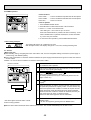
Series PKH Wall Mounted
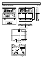
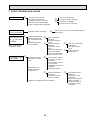
Indoor unit
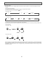
[Model names]
This manual does not cover the
following outdoor units. When servicing them, please refer to the
service manual No.OC150 and
this manual in a set.
[Service Ref.]
PKH-1.6FKA-E
PKH-2FKA-E
PKH-2.5FKA-E
PKH-3FKA-E
PKH-4FKSA-E
PKH-1.6FKA
PKH-2FKA
PKH-2.5FKA
PKH-3FKA
PKH-4FKSA
[Service Ref.]
PUH-1.6VKA3.UK
PUH-2VKA2.UK
PUH-2.5VKA2.UK
PUH-3VKA2.UK
PUH-3YKA2.UK
PUH-4YKSA2.UK
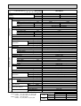
CONTENTS
INDOOR UNIT
FILTER
CHECK MODE
TEST RUN
REMOTE CONTROLLER
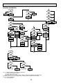
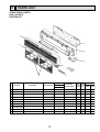
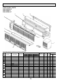
1. PART NAMES AND FUNCTIONS ········2
2. SPECIFICATIONS·································4
3. DATA ·····················································9
4. OUTLINES AND DIMENSIONS··········23
5. WIRING DIAGRAM·····························27
6. REFRIGERANT SYSTEM DIAGRAM ······29
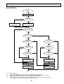
7. OPERATION FLOW-CHART ··············30
8. MICROPROCESSOR CONTROL·······34
9. TROUBLESHOOTING ························56
10. SYSTEM CONTROL ···························65
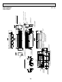
11. DISASSEMBLY PROCEDURE ···········70
12. PARTS LIST········································73
13. OPTIONAL PARTS ·····························79
The Slim Line.
From Mitsubishi Electric.
1
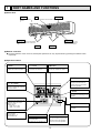
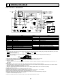
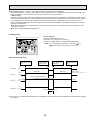
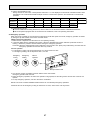
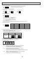
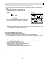
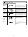
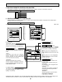
PART NAMES AND FUNCTIONS
● Indoor Unit
Air intake
Filter
room air is suctioned
in here.
Air intake grill
(Removes dust and dirt from the intake air.)
Guide vane
Swing louvers
Air flow can be changed to horizontally
by moving the Guide vane to the left or
right.
Disperses airflow up and
down as well as adjusts the
angle of air flow direction.
Air outlet
Air outlet
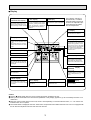
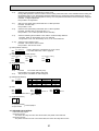
● Remote controller
● Once the operation of the unit is set, subsequent operations can only be performed by pressing the ON/OFF button
repeatedly.
● Operation buttons
w button
q button
l button
This switches between continuous
operation and the timer operation
This sets or switches the current
time, start time and stop time.
The sets the ventilation fan speed.
ON/OFF button
This switches between the operation
and stop modes each time it is
pressed. The lamp on this button
lights during operation.
a button
Press this button to switch the cooler
electronic dry (dehumidify), automatic and heater modes.
FILTER
CHECK MODE
TEST RUN
j button
This adjusts the vertical angle of the
ventilation.
i TEMP. button
This sets the room temperature. The
temperature setting can be performed in 1°C units.
Setting range :
Cooler 19°C to 30°C
Heater 17°C to 28°C
The model name of the remote controller is indicated.
PAR-JH241KA(2.5 ~ 4)
PAR-JH150KA(1.6/2)
241
FILTER button
This resets the filter service indication display
k button
This switches the horizontal fan
motion ON and OFF.
(This button does not operate in this
model.)
CHECK-TEST RUN button
Only press this button to perform an
inspection check or test operation.
Do not use it for normal operation
2
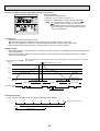
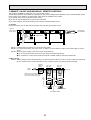
● Display
CENTRALLY
CONTROLLED display
r display
This indicates when the unit is controlled by optional features such as
central control type remote controller.
The current time , start time and stop
time can be displayed in ten second
intervals by pressing the time switch
button. The start time or stop time is
always displayed during the timer
operation.
l display
The selected fan speed is displayed.
In this display example on
the bottom left, a condition
where all display lamps light
is shown for explanation purposes although this differs
from actual operation.
j display
This indicates the air direction.
w display
88°C display
This indicates when the continuous
operation and time operation modes
are set.
It also display the time for the timer
operation at the same time as when
it is set.
FILTER
CHECK MODE
TEST RUN
OPERATION MODE display
The temperature of the suction air is
displayed during operation. The display range is 8° to 39°C. The display
flashes 8°C when the actual temperature is less than 8° and flashes
39°C when the actual temperature is
greater than 39°C.
This indicates the operation mode.
Operation lamp
STANDBY display
This lamp lights during operation,
goes off when the unit stops and
flashes when a malfunction occurs.
241
This indicates when the standby
mode is set from the time the sleep
operation starts until the heating air
is discharged.
CHECK MODE
DEFROST display
TEST RUN
This indicates when the defrost operation is performed.
display
This display lights in the check mode
or when a test operation is performed.
CHECK display
Display
88°C display
This indicates when a malfunction
has occurred in the unit which should
be checked.
This lamp lights when electricity is
supplied to the unit.
This displays the selected setting
temperature.
FILTER display
This display lights when the filter
need to be cleaned.
Caution
● Only the
display lights when the unit is stopped and power supplied to the unit.
● When power is turned ON for the first time the (CENTRAL CTRL) display appears to go off momentarily but this is not a
malfunction.
● When the central control remote control unit, which is sold separately, is used the ON-OFF button, a button and
i TEMP button do not operate.
● “NOT AVAILABLE” is displayed when the k button are pressed.This indicates that this room unit is not equipped with
the fan direction adjustment function and the louver function.
3
2
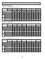
Item
Function
SPECIFICATIONS
Service Ref.
Capacity
PKH-1.6FKA-E
Cooling
4,500
15,350
1.51
W
Btu/h
kW
Total input
Service Ref.
Power supply(phase,cycle,voltage)
Input
kW
Running current
A
Starting current
A
External finish
Heat exchanger
Fan
Fan(drive) ✕ No.
Fan motor output
kW
Airflow(Low-High)
m3/X<CFM>
External static pressure
Pa(mmAq)
Booster heater
kW
Operation control & Thermostat
Noise level(Low-High)
>
Unit drain pipe O.D.
A(in.)
W
A(in.)
Dimensions
D
A(in.)
H
A(in.)
Weight
kg(lbs)
Service Ref.
Power supply (phase, cycle, voltage)
Input
kW
Running current
A
Starting current
A
External finish
Refrigerant control
Compressor
Model
Motor output
kW
Starter type
Protection devices
Heat exchanger
Fan
Fan(drive)✕No.
Fan motor output
kW
Airflow
m3/X<CFM>
Defrost method
Noise level
>
A(in.)
W
Dimensions
A(in.)
D
A(in.)
H
Weight
kg(lbs)
Refrigerant
Charge
kg(lbs)
Oil<Model>
L
Liquid
A(in.)
Pipe size O.D.
Gas
A(in.)
Indoor side
Connection method
Outdoor side
Height difference
Between the indoor & outdoor unit
Piping length
PKH-1.6FKA-E
Single, 50Hz, 220-240V
OUTDOOR UNIT
INDOOR UNIT
0.07
0.07
0.32
0.32
0.40
0.40
Munsell 3.4Y 7.7/0.8(White)
Plate fin coil
Line flow(direct) ✕ 1
0.030
10-13(353-459)
0(direct blow)
—
Remote controller & built-in
36-43
20(13/16)
1,250(49-3/16)
200(7-7/8)
300(11-13/16)
17(37)
PUH-1.6VKA3.UK
Single, 50Hz, 220-240V
1.44
1.41
6.74
6.60
33
Munsell 5Y 7/1
Capillary tube
Hermetic
RH247VFCT
1.2
Line start
Internal thermostat, HP switch
Plate fin coil
Propeller (direct) ✕ 1
0.065
45(1,590)
Reverse cycle
49
870(34-1/4)
295+24(11-5/8 add 1)
650(25-5/8)
53(117)
R-22
2.2(4.9)
0.57<MS-56>
9.52(3/8)
15.88(5/8)
Flared
Flared
Max. 40m
Max. 40m
REFRIGERANT PIPING
Note1. Rating Conditions (JIS B 8616)
Cooling : Indoor : 27°C (80°F) DB, 19°C (66°F) WB
Outdoor : 35°C (95°F) DB, 24°C (75°F) WB
Heating : Indoor : 20°C (68°F) DB
Outdoor : 7°C (45°F) DB, 6°C (43°F) WB
Heating
4,650
15,900
1.48
2. Guaranteed operating range
Cooling
Heating
4
Upper limit
Lower limit
Upper limit
Lower limit
Indoor
Outdoor
35: DB, 22.5: WB
46: DB
21: DB, 15.5: WB
-5: DB
27: DB
21: DB, 15.5: WB
20: DB
-8.5: DB, -9.5: WB
Item
Function
Service Ref.
Capacity
PKH-2FKA-E
Cooling
5,500
18,800
2.27
W
Btu/h
kW
Total input
Service Ref.
Power supply(phase,cycle,voltage)
Input
kW
Running current
A
Starting current
A
External finish
Heat exchanger
Fan
Fan(drive) ✕ No.
Fan motor output
kW
Airflow(Low-High)
m3/X<CFM>
External static pressure
Pa(mmAq)
Booster heater
kW
Operation control & Thermostat
Noise level(Low-High)
>
Unit drain pipe O.D.
A(in.)
W
A(in.)
Dimensions
D
A(in.)
H
A(in.)
Weight
kg(lbs)
Service Ref.
Power supply (phase, cycle, voltage)
Input
kW
Running current
A
Starting current
A
External finish
Refrigerant control
Compressor
Model
Motor output
kW
Starter type
Protection devices
Heat exchanger
Fan
Fan(drive)✕No.
Fan motor output
kW
Airflow
m3/X<CFM>
Defrost method
Noise level
>
A(in.)
W
Dimensions
A(in.)
D
A(in.)
H
Weight
kg(lbs)
Refrigerant
Charge
kg(lbs)
Oil<Model>
L
Liquid
A(in.)
Pipe size O.D.
Gas
A(in.)
Indoor side
Connection method
Outdoor side
Height difference
Between the indoor & outdoor unit
Piping length
PKH-2FKA-E
Single, 50Hz, 220-240V
OUTDOOR UNIT
INDOOR UNIT
0.07
0.07
0.32
0.32
0.40
0.40
Munsell 3.4Y 7.7/0.8(White)
Plate fin coil
Line flow(direct) ✕ 1
0.030
10-13(353-459)
0(direct blow)
—
Remote controller & built-in
36-43
20(13/16)
1,250(49-3/16)
200(7-7/8)
300(11-13/16)
17(37)
PUH-2VKA2.UK
Single, 50Hz, 220-240V
2.20
2.22
9.86
9.95
45
Munsell 5Y 7/1
Capillary tube
Hermetic
NH38VMDT
1.7
Line start
Internal thermostat, HP switch
Plate fin coil
Propeller (direct) ✕ 1
0.065
45(1,590)
Reverse cycle
49
870(34-1/4)
295+24(11-5/8 add 1)
650(25-5/8)
64(141)
R-22
2.2(4.9)
1.2<MS-32>
9.52(3/8)
15.88(5/8)
Flared
Flared
Max. 40m
Max. 40m
REFRIGERANT PIPING
Note1. Rating Conditions (JIS B 8616)
Cooling : Indoor : 27°C (80°F) DB, 19°C (66°F) WB
Outdoor : 35°C (95°F) DB, 24°C (75°F) WB
Heating : Indoor : 20°C (68°F) DB
Outdoor : 7°C (45°F) DB, 6°C (43°F) WB
Heating
6,250
21,300
2.29
2. Guaranteed operating range
Cooling
Heating
5
Upper limit
Lower limit
Upper limit
Lower limit
Indoor
Outdoor
35: DB, 22.5: WB
46: DB
21: DB, 15.5: WB
-5: DB
27: DB
21: DB, 15.5: WB
20: DB
-8.5: DB, -9.5: WB
Item
Function
Service Ref.
Capacity
PKH-2.5FKA-E
Cooling
6,500
22,200
2.56
W
Btu/h
kW
Total input
Service Ref.
Power supply(phase,cycle,voltage)
Input
kW
Running current
A
Starting current
A
External finish
Heat exchanger
Fan
Fan(drive) ✕ No.
Fan motor output
kW
Airflow(Low-High)
m3/X<CFM>
External static pressure
Pa(mmAq)
Booster heater
kW
Operation control & Thermostat
Noise level(Low-High)
>
Unit drain pipe O.D.
A(in.)
W
A(in.)
Dimensions
D
A(in.)
H
A(in.)
Weight
kg(lbs)
Service Ref.
Power supply (phase, cycle, voltage)
Input
kW
Running current
A
Starting current
A
External finish
Refrigerant control
Compressor
Model
Motor output
kW
Starter type
Protection devices
Heat exchanger
Fan
Fan(drive)✕No.
Fan motor output
kW
Airflow
m3/X<CFM>
Defrost method
Noise level
>
A(in.)
W
Dimensions
A(in.)
D
A(in.)
H
Weight
kg(lbs)
Refrigerant
Charge
kg(lbs)
Oil<Model>
L
Liquid
A(in.)
Pipe size O.D.
Gas
A(in.)
Indoor side
Connection method
Outdoor side
Height difference
Between the indoor & outdoor unit
Piping length
PKH-2.5FKA-E
Single, 50Hz, 220-240V
OUTDOOR UNIT
INDOOR UNIT
0.095
0.095
0.44
0.44
0.80
0.80
Munsell 3.4Y 7.7/0.8(White)
Plate fin coil
Line flow(direct) ✕ 2
0.040
15-20(530-706)
0(direct blow)
—
Remote controller & built-in
39-45
20(13/16)
1,400(55-1/8)
235(9-1/4)
340(13-3/8)
24(53)
PUH-2.5VKA2.UK
Single, 50Hz, 220-240V
2.46
2.23
10.68
9.78
52
Munsell 5Y 7/1
Capillary tube
Hermetic
NH41VMDT
2.0
Line start
Internal thermostat, HP switch
Plate fin coil
Propeller (direct) ✕ 1
0.085
50(1,764)
Reverse cycle
52
870(34-1/4)
295+24(11-5/8 add 1)
850(33-7/16)
64(150)
R-22
2.8(6.2)
1.2<MS-32>
9.52(3/8)
15.88(5/8)
Flared
Flared
Max. 50m
Max. 50m
REFRIGERANT PIPING
Note1. Rating Conditions (JIS B 8616)
Cooling : Indoor : 27°C (80°F) DB, 19°C (66°F) WB
Outdoor : 35°C (95°F) DB, 24°C (75°F) WB
Heating : Indoor : 20°C (68°F) DB
Outdoor : 7°C (45°F) DB, 6°C (43°F) WB
Heating
7,200
24,600
2.33
2. Guaranteed operating range
Cooling
Heating
6
Upper limit
Lower limit
Upper limit
Lower limit
Indoor
Outdoor
35: DB, 22.5: WB
46: DB
21: DB, 15.5: WB
-5: DB
27: DB
21: DB, 15.5: WB
20: DB
-8.5: DB, -9.5: WB
Item
Function
Service Ref.
Capacity
Cooling
7,900
27,000
3.25
W
Btu/h
kW
REFRIGERANT PIPING
OUTDOOR UNIT
INDOOR UNIT
Total input
Service Ref.
Power supply(phase,cycle,voltage)
Input
kW
Running current
A
Starting current
A
External finish
Heat exchanger
Fan
Fan(drive) ✕ No.
Fan motor output
kW
Airflow(Low-High)
m3/X<CFM>
External static pressure
Pa(mmAq)
Booster heater
kW
Operation control & Thermostat
Noise level(Low-High)
>
Unit drain pipe O.D.
A(in.)
W
A(in.)
Dimensions
D
A(in.)
H
A(in.)
Weight
kg(lbs)
Service Ref.
Power supply (phase, cycle, voltage)
Input
kW
Running current
A
Starting current
A
External finish
Refrigerant control
Compressor
Model
Motor output
kW
Starter type
Protection devices
Heat exchanger
Fan
Fan(drive)✕No.
Fan motor output
kW
Airflow
m3/X<CFM>
Defrost method
Noise level
>
A(in.)
W
Dimensions
A(in.)
D
A(in.)
H
Weight
kg(lbs)
Refrigerant
Charge
kg(lbs)
Oil<Model>
L
Liquid
A(in.)
Pipe size O.D.
Gas
A(in.)
Indoor side
Connection method
Outdoor side
Height difference
Between the indoor & outdoor unit
Piping length
Note1. Rating Conditions (JIS B 8616)
Cooling : Indoor : 27°C (80°F) DB, 19°C (66°F) WB
Outdoor : 35°C (95°F) DB, 24°C (75°F) WB
Heating : Indoor : 20°C (68°F) DB
Outdoor : 7°C (45°F) DB, 6°C (43°F) WB
PKH-3FKA-E
Heating
9,100
31,000
3.04
PKH-3FKA-E
Single, 50Hz, 220-240V
0.095
0.095
0.44
0.44
0.80
0.80
Munsell 3.4Y 7.7/0.8(White)
Plate fin coil
Line flow(direct) ✕ 2
0.040
15-20(530-706)
0(direct blow)
—
Remote controller & built-in
39-45
20(13/16)
1,400(55-1/8)
235(9-1/4)
340(13-3/8)
24(53)
PUH-3VKA2.UK / PUH-3YKA2.UK
Single, 50Hz, 220-240V/3, 50Hz, 380-415V(4wires)
3.15/3.15
2.94/2.94
13.82/5.16
12.89/4.81
58/37
Munsell 5Y 7/1
Capillary tube
Hermetic
NH52VNDT/NH52YDAT
2.2/2.4
Line start
Internal thermostat, HP switch/Thermal relay, thermal switch
Plate fin coil
Propeller (direct) ✕ 1
0.085
50(1,764)
Reverse cycle
52
870(34-1/4)
295+24(11-5/8 add 1)
850(33-7/16)
75(165)
R-22
3.2(7.1)
1.6<MS-32>
9.52(3/8)
15.88(5/8)
Flared
Flared
Max. 50m
Max. 50m
2. Guaranteed operating range
Cooling
Heating
7
Upper limit
Lower limit
Upper limit
Lower limit
Indoor
Outdoor
35: DB, 22.5: WB
46: DB
21: DB, 15.5: WB
-5: DB
27: DB
21: DB, 15.5: WB
20: DB
-8.5: DB, -9.5: WB
Item
Function
Service Ref.
Capacity
INDOOR UNIT
OUTDOOR UNIT
REFRIGERANT PIPING
Cooling
9,500
32,400
3.31
W
Btu/h
kW
Total input
Service Ref.
Power supply(phase,cycle,voltage)
kW
Input
A
Running current
A
Starting current
External finish
Heat exchanger
Fan
Fan(drive) ✕ No.
kW
Fan motor output
m3/X<CFM>
Airflow(Low-High)
Pa(mmAq)
External static pressure
kW
Booster heater
Operation control & Thermostat
>
Noise level(Low-High)
A(in.)
Unit drain pipe O.D.
A(in.)
W
A(in.)
Dimensions
D
A(in.)
H
kg(lbs)
Weight
Service Ref.
Power supply (phase, cycle, voltage)
kW
Input
A
Running current
A
Starting current
External finish
Refrigerant control
Compressor
Model
kW
Motor output
Starter type
Protection devices
Heat exchanger
Fan
Fan(drive)✕No.
kW
Fan motor output
m3/X<CFM>
Airflow
Defrost method
>
Noise level
A(in.)
W
A(in.)
Dimensions
D
A(in.)
H
kg(lbs)
Weight
Refrigerant
kg(lbs)
Charge
L
Oil<Model>
Liquid
A(in.)
Pipe size O.D.
Gas
A(in.)
Indoor side
Connection method
Outdoor side
Height difference
Between the indoor & outdoor unit
Piping length
Note1. Rating Conditions (JIS B 8616)
Cooling : Indoor : 27°C (80°F) DB, 19°C (66°F) WB
Outdoor : 35°C (95°F) DB, 24°C (75°F) WB
Heating : Indoor : 20°C (68°F) DB
Outdoor : 7°C (45°F) DB, 6°C (43°F) WB
PKH-4FKSA-E
Heating
10,700
36,500
3.30
PKH-4FKSA-E
Single, 50Hz, 220-240V
0.114
0.114
0.53
0.53
0.90
0.90
Munsell 3.4Y 7.7/0.8(White)
Plate fin coil
Line flow(direct) ✕ 2
0.070
22-28(777-989)
0(direct blow)
—
Remote controller & built-in
41-46
20(13/16)
1,680(66-1/8)
235(9-1/4)
340(13-3/8)
28(62)
PUH-4YKSA2.UK
3, 50Hz, 380-415V(4wires)
3.20
3.19
5.24
5.22
40
Munsell 5Y 7/1
Capillary tube
Hermetic
NH56YDAT
2.7
Line start
Thermal relay, thermal swich, HP switch, anti-phase protector
Plate fin coil
Propeller (direct) ✕ 2
0.065+0.065
95(3,350)
Reverse cycle
54
870(34-1/4)
295+24(11-5/8 add 1)
1,258(49-1/2)
94(207)
R-22
4.2(9.2)
1.6<MS-32>
9.52(3/8)
19.05(3/4)
Flared
Flared
Max. 50m
Max. 50m
2. Guaranteed operating range
Cooling
Heating
8
Upper limit
Lower limit
Upper limit
Lower limit
Indoor
Outdoor
35: DB, 22.5: WB
46: DB
21: DB, 15.5: WB
-5: DB
27: DB
21: DB, 15.5: WB
20: DB
-8.5: DB, -9.5: WB
3
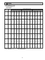
DATA
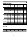
1. PERFORMANCE DATA
1) COOLING CAPACITY<1>
PKH-1.6FKA-E
Indoor
Indoor
Intake air Intake air
°C DB
°C WB
CA
20
SHC(W) SHF
P.C.
Outdoor intake air °C DB
25
CA SHC(W) SHF
P.C.
CA
30
SHC(W) SHF
P.C.
20
16
4540
3042
0.67
1.21
4415
2958
0.67
1.26
4253
2850
0.67
1.36
20
18
4834
2659
0.55
1.23
4706
2589
0.55
1.29
4535
2494
0.55
1.39
20
20
5131
2206
0.43
1.26
5010
2154
0.43
1.31
4831
2077
0.43
1.42
22
16
4540
3405
0.75
1.21
4415
3312
0.75
1.26
4253
3190
0.75
1.36
22
18
4834
3045
0.63
1.23
4706
2965
0.63
1.29
4535
2857
0.63
1.39
22
20
5131
2617
0.51
1.26
5010
2555
0.51
1.31
4831
2464
0.51
1.42
24
16
4540
3768
0.83
1.21
4415
3665
0.83
1.26
4253
3530
0.83
1.36
24
18
4834
3432
0.71
1.23
4706
3342
0.71
1.29
4535
3220
0.71
1.39
24
20
5131
3027
0.59
1.26
5010
2956
0.59
1.31
4831
2851
0.59
1.42
24
22
5431
2553
0.47
1.28
5327
2504
0.47
1.34
5142
2417
0.47
1.45
26
16
4540
4131
0.91
1.21
4415
4018
0.91
1.26
4253
3870
0.91
1.36
26
18
4834
3819
0.79
1.23
4706
3718
0.79
1.29
4535
3583
0.79
1.39
26
20
5131
3438
0.67
1.26
5010
3357
0.67
1.31
4831
3237
0.67
1.42
26
22
5431
2987
0.55
1.28
5327
2930
0.55
1.34
5142
2828
0.55
1.45
27
16
4540
4313
0.95
1.21
4415
4195
0.95
1.26
4253
4041
0.95
1.36
27
18
4834
4012
0.83
1.23
4706
3906
0.83
1.29
4535
3764
0.83
1.39
27
20
5131
3643
0.71
1.26
5010
3557
0.71
1.31
4831
3430
0.71
1.42
27
22
5431
3204
0.59
1.28
5327
3143
0.59
1.34
5142
3034
0.59
1.45
28
16
4540
4494
0.99
1.21
4415
4371
0.99
1.26
4253
4211
0.99
1.36
28
18
4834
4205
0.87
1.23
4706
4095
0.87
1.29
4535
3945
0.87
1.39
28
20
5131
3848
0.75
1.26
5010
3758
0.75
1.31
4831
3624
0.75
1.42
28
22
5431
3422
0.63
1.28
5327
3356
0.63
1.34
5142
3240
0.63
1.45
30
16
4540
4540
1.00
1.21
4415
4415
1.00
1.26
4253
4253
1.00
1.36
30
18
4834
4592
0.95
1.23
4706
4471
0.95
1.29
4535
4308
0.95
1.39
30
20
5131
4259
0.83
1.26
5010
4158
0.83
1.31
4831
4010
0.83
1.42
30
22
5431
3856
0.71
1.28
5327
3782
0.71
1.34
5142
3651
0.71
1.45
32
16
4540
4540
1.00
1.21
4415
4415
1.00
1.26
4253
4253
1.00
1.36
32
18
4834
4834
1.00
1.23
4706
4706
1.00
1.29
4535
4535
1.00
1.39
32
20
5131
4669
0.91
1.26
5010
4559
0.91
1.31
4831
4397
0.91
1.42
32
22
5431
4290
0.79
1.28
5327
4208
0.79
1.34
5142
4062
0.79
1.45
Notes CA : Capacity (W)
P.C. : Power consumption (kW)
SHC(W) : Sensible heat capacity
SHF : Sensible heat factor
9
COOLING CAPACITY<2>
PKH-1.6FKA-E
Indoor
Indoor
Intake air Intake air
°C DB
°C WB
CA
35
SHC(W) SHF
P.C.
Outdoor intake air °C DB
40
CA SHC(W) SHF
P.C.
CA
45
SHC(W) SHF
P.C.
20
16
4081
2734
0.67
1.46
3899
2612
0.67
1.55
3706
2483
0.67
1.65
20
18
4355
2395
0.55
1.49
4167
2292
0.55
1.59
3970
2183
0.55
1.70
20
20
4645
1997
0.43
1.53
4451
1914
0.43
1.64
4249
1827
0.43
1.75
22
16
4081
3061
0.75
1.46
3899
2924
0.75
1.55
3706
2780
0.75
1.65
22
18
4355
2744
0.63
1.49
4167
2625
0.63
1.59
3970
2501
0.63
1.70
22
20
4645
2369
0.51
1.53
4451
2270
0.51
1.64
4249
2167
0.51
1.75
24
16
4081
3387
0.83
1.46
3899
3236
0.83
1.55
3706
3076
0.83
1.65
24
18
4355
3092
0.71
1.49
4167
2958
0.71
1.59
3970
2819
0.71
1.70
24
20
4645
2740
0.59
1.53
4451
2626
0.59
1.64
4249
2507
0.59
1.75
24
22
4950
2327
0.47
1.56
4750
2233
0.47
1.68
4543
2135
0.47
1.81
26
16
4081
3714
0.91
1.46
3899
3548
0.91
1.55
3706
3373
0.91
1.65
26
18
4355
3441
0.79
1.49
4167
3292
0.79
1.59
3970
3136
0.79
1.70
26
20
4645
3112
0.67
1.53
4451
2982
0.67
1.64
4249
2847
0.67
1.75
26
22
4950
2723
0.55
1.56
4750
2613
0.55
1.68
4543
2499
0.55
1.81
27
16
4081
3877
0.95
1.46
3899
3704
0.95
1.55
3706
3521
0.95
1.65
27
18
4355
3615
0.83
1.49
4167
3458
0.83
1.59
3970
3295
0.83
1.70
27
20
4645
3298
0.71
1.53
4451
3160
0.71
1.64
4249
3017
0.71
1.75
27
22
4950
3921
0.59
1.56
4750
2803
0.59
1.68
4543
2680
0.59
1.81
28
16
4081
4040
0.99
1.46
3899
3860
0.99
1.55
3706
3669
0.99
1.65
28
18
4355
3789
0.87
1.49
4167
3625
0.87
1.59
3970
3454
0.87
1.70
28
20
4645
3484
0.75
1.53
4451
3338
0.75
1.64
4249
3187
0.75
1.75
28
22
4950
3119
0.63
1.56
4750
2993
0.63
1.68
4543
2862
0.63
1.81
30
16
4081
4081
1.00
1.46
3899
3899
1.00
1.55
3706
3706
1.00
1.65
30
18
4355
4137
0.95
1.49
4167
3958
0.95
1.59
3970
3771
0.95
1.70
30
20
4645
3855
0.83
1.53
4451
3694
0.83
1.64
4249
3527
0.83
1.75
30
22
4950
3515
0.71
1.56
4750
3373
0.71
1.68
4543
3225
0.71
1.81
32
16
4081
4081
1.00
1.46
3899
3899
1.00
1.55
3706
3706
1.00
1.65
32
18
4355
4355
1.00
1.49
4167
4167
1.00
1.59
3970
3970
1.00
1.70
32
20
4645
4227
0.91
1.53
4451
4050
0.91
1.64
4249
3866
0.91
1.75
32
22
4950
3911
0.79
1.56
4750
3753
0.79
1.68
4543
3589
0.79
1.81
Notes CA : Capacity (W)
P.C. : Power consumption (kW)
SHC(W) : Sensible heat capacity
SHF : Sensible heat factor
10
COOLING CAPACITY<3>
PKH-2FKA-E
Indoor
Indoor
Intake air Intake air
°C DB
°C WB
CA
20
SHC(W) SHF
P.C.
Outdoor intake air °C DB
25
CA SHC(W) SHF
P.C.
CA
30
SHC(W) SHF
P.C.
20
16
5549
3385
0.61
1.82
5397
3292
0.61
1.90
5198
3171
0.61
2.04
20
18
5908
2895
0.49
1.86
5752
2819
0.49
1.94
5543
2716
0.49
2.09
20
20
6271
2320
0.37
1.89
6124
2266
0.37
1.97
5905
2185
0.37
2.13
22
16
5549
3829
0.69
1.82
5397
3724
0.69
1.90
5198
3587
0.69
2.04
22
18
5908
3367
0.57
1.86
5752
3279
0.57
1.94
5543
3159
0.57
2.09
22
20
6271
2822
0.45
1.89
6124
2756
0.45
1.97
5905
2657
0.45
2.13
24
16
5549
4272
0.77
1.82
5397
4155
0.77
1.90
5198
4003
0.77
2.04
24
18
5908
3840
0.65
1.86
5752
3739
0.65
1.94
5543
3603
0.65
2.09
24
20
6271
3324
0.53
1.89
6124
3245
0.53
1.97
5905
3130
0.53
2.13
24
22
6638
2722
0.41
1.93
6511
2669
0.41
2.01
6285
2577
0.41
2.18
26
16
5549
4716
0.85
1.82
5397
4587
0.85
1.90
5198
4419
0.85
2.04
26
18
5908
4313
0.73
1.86
5752
4199
0.73
1.94
5543
4046
0.73
2.09
26
20
6271
3825
0.61
1.89
6124
3735
0.61
1.97
5905
3602
0.61
2.13
26
22
6638
3253
0.49
1.93
6511
3190
0.49
2.01
6285
3080
0.49
2.18
27
16
5549
4938
0.89
1.82
5397
4803
0.89
1.90
5198
4627
0.89
2.04
27
18
5908
4549
0.77
1.86
5752
4429
0.77
1.94
5543
4268
0.77
2.09
27
20
6271
4076
0.65
1.89
6124
3980
0.65
1.97
5905
3838
0.65
2.13
27
22
6638
3518
0.53
1.93
6511
3451
0.53
2.01
6285
3331
0.53
2.18
28
16
5549
5160
0.93
1.82
5397
5019
0.93
1.90
5198
4835
0.93
2.04
28
18
5908
4785
0.81
1.86
5752
4659
0.81
1.94
5543
4490
0.81
2.09
28
20
6271
4327
0.69
1.89
6124
4225
0.69
1.97
5905
4074
0.69
2.13
28
22
6638
3784
0.57
1.93
6511
3711
0.57
2.01
6285
3583
0.57
2.18
30
16
5549
5549
1.00
1.82
5397
5397
1.00
1.90
5198
5198
1.00
2.04
30
18
5908
5258
0.89
1.86
5752
5119
0.89
1.94
5543
4933
0.89
2.09
30
20
6271
4829
0.77
1.89
6124
4715
0.77
1.97
5905
4547
0.77
2.13
30
22
6638
4315
0.65
1.93
6511
4232
0.65
2.01
6285
4085
0.65
2.18
32
16
5549
5549
1.00
1.82
5397
5397
1.00
1.90
5198
5198
1.00
2.04
32
18
5908
5731
0.97
1.86
5752
5580
0.97
1.94
5543
5376
0.97
2.09
32
20
6271
5330
0.85
1.89
6124
5205
0.85
1.97
5905
5019
0.85
2.13
32
22
6638
4846
0.73
1.93
6511
4753
0.73
2.01
6285
4588
0.73
2.18
Notes CA : Capacity (W)
P.C. : Power consumption (kW)
SHC(W) : Sensible heat capacity
SHF : Sensible heat factor
11
COOLING CAPACITY<4>
PKH-2FKA-E
Indoor
Indoor
Intake air Intake air
°C DB
°C WB
CA
35
SHC(W) SHF
P.C.
Outdoor intake air °C DB
40
CA SHC(W) SHF
P.C.
CA
45
SHC(W) SHF
P.C.
20
16
4988
3043
0.61
2.19
4765
2907
0.61
2.34
4530
2763
0.61
2.49
20
18
5323
2608
0.49
2.24
5093
2495
0.49
2.40
4852
2378
0.49
2.55
20
20
5677
2101
0.37
2.30
5440
2013
0.37
2.46
5193
1921
0.37
2.63
22
16
4988
3442
0.69
2.19
4765
3288
0.69
2.34
4530
3125
0.69
2.49
22
18
5323
3034
0.57
2.24
5093
2903
0.57
2.40
4852
2766
0.57
2.55
22
20
5677
2555
0.45
2.30
5440
2448
0.45
2.46
5193
2337
0.45
2.63
24
16
4988
3841
0.77
2.19
4765
3669
0.77
2.34
4530
3488
0.77
2.49
24
18
5323
3460
0.65
2.24
5093
3310
0.65
2.40
4852
3154
0.65
2.55
24
20
5677
3009
0.53
2.30
5440
2883
0.53
2.46
5193
2752
0.53
2.63
24
22
6050
2481
0.41
2.35
5806
2380
0.41
2.53
5552
2276
0.41
2.71
26
16
4988
4240
0.85
2.19
4765
4050
0.85
2.34
4530
3850
0.85
2.49
26
18
5323
3886
0.73
2.24
5093
3718
0.73
2.40
4852
3542
0.73
2.55
26
20
5677
3463
0.61
2.30
5440
3318
0.61
2.46
5193
3168
0.61
2.63
26
22
6050
2965
0.49
2.35
5806
2845
0.49
2.53
5552
2721
0.49
2.71
27
16
4988
4439
0.89
2.19
4765
4241
0.89
2.34
4530
4031
0.89
2.49
27
18
5323
4099
0.77
2.24
5093
3921
0.77
2.40
4852
3736
0.77
2.55
27
20
5677
3690
0.65
2.30
5440
3536
0.65
2.46
5193
3376
0.65
2.63
27
22
6050
3207
0.53
2.35
5806
3077
0.53
2.53
5552
2943
0.53
2.71
28
16
4988
4639
0.93
2.19
4765
4431
0.93
2.34
4530
4213
0.93
2.49
28
18
5323
4312
0.81
2.24
5093
4125
0.81
2.40
4852
3930
0.81
2.55
28
20
5677
3917
0.69
2.30
5440
3753
0.69
2.46
5193
3583
0.69
2.63
28
22
6050
3449
0.57
2.35
5806
3309
0.57
2.53
5552
3165
0.57
2.71
30
16
4988
4988
1.00
2.19
4765
4765
1.00
2.34
4530
4560
1.00
2.49
30
18
5323
4737
0.89
2.24
5093
4533
0.89
2.40
4852
4318
0.89
2.55
30
20
5677
4371
0.77
2.30
5440
4189
0.77
2.46
5193
3999
0.77
2.63
30
22
6050
3933
0.65
2.35
5806
3774
0.65
2.53
5552
3609
0.65
2.71
32
16
4988
4988
1.00
2.19
4765
4765
1.00
2.34
4530
4530
1.00
2.49
32
18
5323
5163
0.97
2.24
5093
4940
0.97
2.40
4852
4707
0.97
2.55
32
20
5677
4826
0.85
2.30
5440
4624
0.85
2.46
5193
4414
0.85
2.63
32
22
6050
4417
0.73
2.35
5806
4238
0.73
2.53
5552
4053
0.73
2.71
Notes CA : Capacity (W)
P.C. : Power consumption (kW)
SHC(W) : Sensible heat capacity
SHF : Sensible heat factor
12
COOLING CAPACITY<5>
PKH-2.5FKA-E
Indoor
Indoor
Intake air Intake air
°C DB
°C WB
CA
20
SHC(W) SHF
P.C.
Outdoor intake air °C DB
25
CA SHC(W) SHF
P.C.
CA
30
SHC(W) SHF
P.C.
20
16
6557
4787
0.73
2.05
6378
4656
0.73
2.14
6144
4485
0.73
2.30
20
18
6982
4259
0.61
2.09
6798
4147
0.61
2.18
6551
3996
0.61
2.36
20
20
7411
3631
0.49
2.13
7237
3546
0.49
2.23
6979
3420
0.49
2.41
22
16
6557
5312
0.81
2.05
6378
5166
0.81
2.14
6144
4976
0.81
2.30
22
18
6982
4818
0.69
2.09
6798
4691
0.69
2.18
6551
4520
0.69
2.36
22
20
7411
4224
0.57
2.13
7237
4125
0.57
2.23
6979
3978
0.57
2.41
24
16
6557
5836
0.89
2.05
6378
5676
0.89
2.14
6144
5468
0.89
2.30
24
18
6982
5376
0.77
2.09
6798
5235
0.77
2.18
6551
5044
0.77
2.36
24
20
7411
4817
0.65
2.13
7237
4704
0.65
2.23
6979
4536
0.65
2.41
24
22
7845
4158
0.53
2.17
7694
4078
0.53
2.27
7428
3937
0.53
2.46
26
16
6557
6361
0.97
2.05
6378
6187
0.97
2.14
6144
5959
0.97
2.30
26
18
6982
5936
0.85
2.09
6798
5778
0.85
2.18
6551
5568
0.85
2.36
26
20
7411
5412
0.73
2.13
7237
5283
0.73
2.23
6979
5094
0.73
2.41
26
22
7845
4785
0.61
2.17
7694
4694
0.61
2.27
7428
4531
0.61
2.46
27
16
6557
6557
1.00
2.05
6378
6378
1.00
2.14
6144
6144
1.00
2.30
27
18
6982
6214
0.89
2.09
6798
6050
0.89
2.18
6551
5830
0.89
2.36
27
20
7411
5707
0.77
2.13
7237
5572
0.77
2.23
6979
5374
0.77
2.41
27
22
7845
5099
0.65
2.17
7694
5001
0.65
2.27
7428
4828
0.65
2.46
28
16
6557
6557
1.00
2.05
6378
6378
1.00
2.14
6144
6144
1.00
2.30
28
18
6982
6493
0.93
20.9
6798
6322
0.93
2.18
6551
6092
0.93
2.36
28
20
7411
6003
0.81
2.13
7237
5862
0.81
2.23
6979
5653
0.81
2.41
28
22
7845
5413
0.69
2.17
7694
5309
0.69
2.27
7428
5125
0.69
2.46
30
16
6557
6557
1.00
2.05
6378
6378
1.00
2.14
6144
6144
1.00
2.30
30
18
6982
6982
1.00
20.9
6798
6798
1.00
2.18
6551
6551
1.00
2.36
30
20
7411
6596
0.89
2.13
7237
6441
0.89
2.23
6979
6211
0.89
2.41
30
22
7845
6040
0.77
2.17
7694
5925
0.77
2.27
7428
5719
0.77
2.46
32
16
6557
6557
1.00
2.05
6378
6378
1.00
2.14
6144
6144
1.00
2.30
32
18
6982
6982
1.00
20.9
6798
6798
1.00
2.18
6551
6551
1.00
2.36
32
20
7411
7189
0.97
2.13
7237
7020
0.97
2.23
6979
6769
0.97
2.41
32
22
7845
6668
0.85
2.17
7694
6540
0.85
2.27
7428
6314
0.85
2.46
Notes CA : Capacity (W)
P.C. : Power consumption (kW)
SHC(W) : Sensible heat capacity
SHF : Sensible heat factor
13
COOLING CAPACITY<6>
PKH-2.5FKA-E
Indoor
Indoor
Intake air Intake air
°C DB
°C WB
CA
35
SHC(W) SHF
P.C.
Outdoor intake air °C DB
40
CA SHC(W) SHF
P.C.
CA
45
SHC(W) SHF
P.C.
20
16
5895
4303
0.73
2.47
5631
4111
0.73
2.64
5353
3908
0.73
2.80
20
18
6291
3837
0.61
2.53
6019
3671
0.61
2.70
5734
3498
0.61
2.88
20
20
6709
3288
0.49
2.59
6429
3150
0.49
2.78
6137
3007
0.49
2.96
22
16
5895
4775
0.81
2.47
5631
4561
0.81
2.64
5353
4336
0.81
2.80
22
18
6291
4341
0.69
2.53
6019
4153
0.69
2.70
5734
3957
0.69
2.88
22
20
6709
3824
0.57
2.59
6429
3664
0.57
2.78
6137
3498
0.57
2.96
24
16
5895
5246
0.89
2.47
5631
5012
0.89
2.64
5353
4764
0.89
2.80
24
18
6291
4844
0.77
2.53
6019
4634
0.77
2.70
5734
4415
0.77
2.88
24
20
6709
4361
0.65
2.59
6429
4179
0.65
2.78
6137
3989
0.65
2.96
24
22
7150
3790
0.53
2.65
6862
3637
0.53
2.85
6562
3478
0.53
3.06
26
16
5895
5718
0.97
2.47
5631
5462
0.97
2.64
5353
5193
0.97
2.80
26
18
6291
5347
0.85
2.53
6019
5116
0.85
2.70
5734
4874
0.85
2.88
26
20
6709
4898
0.73
2.59
6429
4693
0.73
2.78
6137
4480
0.73
2.96
26
22
7150
4362
0.61
2.65
6862
4186
0.61
2.85
6562
4003
0.61
3.06
27
16
5895
5895
1.00
2.47
5631
5631
1.00
2.64
5353
5353
1.00
2.80
27
18
6291
5599
0.89
2.53
6019
5357
0.89
2.70
5734
5104
0.89
2.88
27
20
6709
5166
0.77
2.59
6429
4950
0.77
2.78
6137
4726
0.77
2.96
27
22
7150
4648
0.65
2.65
6862
4460
0.65
2.85
6562
4265
0.65
3.06
28
16
5895
5895
1.00
2.47
5631
5631
1.00
2.64
5353
5353
1.00
2.80
28
18
6291
5850
0.93
2.53
6019
5597
0.93
2.70
5734
5333
0.93
2.88
28
20
6709
5435
0.81
2.59
6429
5207
0.81
2.78
6137
4971
0.81
2.96
28
22
7150
4934
0.69
2.65
6862
4735
0.69
2.85
6562
4528
0.69
3.06
30
16
5895
5895
1.00
2.47
5631
5631
1.00
2.64
5353
5353
1.00
2.80
30
18
6291
6291
1.00
2.53
6019
6019
1.00
2.70
5734
5734
1.00
2.88
30
20
6709
5971
0.89
2.59
6429
5722
0.89
2.78
6137
5462
0.89
2.96
30
22
7150
5506
0.77
2.65
6862
5283
0.77
2.85
6562
5053
0.77
3.06
32
16
5895
5895
1.00
2.47
5631
5631
1.00
2.64
5353
5353
1.00
2.80
32
18
6291
6291
1.00
2.53
6019
6019
1.00
2.70
5734
5734
1.00
2.88
32
20
6709
6508
0.97
2.59
6429
6236
0.97
2.78
6137
5953
0.97
2.96
32
22
7150
6078
0.85
2.65
6862
5832
0.85
2.85
6562
5578
0.85
3.06
Notes CA : Capacity (W)
P.C. : Power consumption (kW)
SHC(W) : Sensible heat capacity
SHF : Sensible heat factor
14
COOLING CAPACITY<7>
PKH-3FKA-E
Indoor
Indoor
Intake air Intake air
°C DB
°C WB
CA
20
SHC(W) SHF
P.C.
Outdoor intake air °C DB
25
CA SHC(W) SHF
P.C.
CA
30
SHC(W) SHF
P.C.
20
16
7970
5101
0.64
2.60
7752
4961
0.64
2.72
7467
4779
0.64
2.92
20
18
8486
4413
0.52
2.66
8262
4296
0.52
2.77
7961
4140
0.52
2.99
20
20
9007
3603
0.40
2.71
8796
3518
0.40
2.83
8482
3393
0.40
3.06
22
16
7970
5738
0.72
2.60
7752
5581
0.72
2.72
7467
5376
0.72
2.92
22
18
8486
5091
0.60
2.66
8262
4957
0.60
2.77
7961
4777
0.60
2.99
22
20
9007
4323
0.48
2.71
8796
4222
0.48
2.83
8482
4071
0.48
3.06
24
16
7970
6376
0.80
2.60
7752
6201
0.80
2.72
7467
5973
0.80
2.92
24
18
8486
5770
0.68
2.66
8262
5618
0.68
2.77
7961
5414
0.68
2.99
24
20
9007
5044
0.56
2.71
8796
4926
0.56
2.83
8482
4750
0.56
3.06
24
22
9534
4195
0.44
2.76
9352
4115
0.44
2.88
9028
3972
0.44
3.12
26
16
7970
7013
0.88
2.60
7752
6821
0.88
2.72
7467
6571
0.88
2.92
26
18
8486
6449
0.76
2.66
8262
6279
0.76
2.77
7961
6051
0.76
2.99
26
20
9007
5765
0.64
2.71
8796
5629
0.64
2.83
8482
5428
0.64
3.06
26
22
9534
4958
0.52
2.76
9352
4863
0.52
2.88
9028
4694
0.52
3.12
27
16
7970
7332
0.92
2.60
7752
7132
0.92
2.72
7467
6869
0.92
2.92
27
18
8486
6789
0.80
2.66
8262
6610
0.80
2.77
7961
6369
0.80
2.99
27
20
9007
6125
0.68
2.71
8796
5981
0.68
2.83
8482
5768
0.68
3.06
27
22
9534
5339
0.56
2.76
9352
5237
0.56
2.88
9028
5056
0.56
3.12
28
16
7970
7651
0.96
2.60
7752
7442
0.96
2.72
7467
7168
0.96
2.92
28
18
8486
7128
0.84
2.66
8262
6940
0.84
2.77
7961
6688
0.84
2.99
28
20
9007
6485
0.72
2.71
8796
6333
0.72
2.83
8482
6107
0.72
3.06
28
22
9534
5721
0.60
2.76
9352
5611
0.60
2.88
9028
5417
0.60
3.12
30
16
7970
7970
1.00
2.60
7752
7752
1.00
2.72
7467
7467
1.00
2.92
30
18
8486
7807
0.92
2.66
8262
7601
0.92
2.77
7961
7325
0.92
2.99
30
20
9007
7206
0.80
2.71
8796
7037
0.80
2.83
8482
6785
0.80
3.06
30
22
9534
6483
0.68
2.76
9352
6359
0.68
2.88
9028
6139
0.68
3.12
32
16
7970
7970
1.00
2.60
7752
7752
1.00
2.72
7467
7467
1.00
2.92
32
18
8486
8486
1.00
2.66
8262
8262
1.00
2.77
7961
7961
1.00
2.99
32
20
9007
7926
0.88
2.71
8796
7740
0.88
2.83
8482
7464
0.88
3.06
32
22
9534
7246
0.76
2.76
9352
7107
0.76
2.88
9028
6861
0.76
3.12
Notes CA : Capacity (W)
P.C. : Power consumption (kW)
SHC(W) : Sensible heat capacity
SHF : Sensible heat factor
15
COOLING CAPACITY<8>
PKH-3FKA-E
Indoor
Indoor
Intake air Intake air
°C DB
°C WB
CA
35
SHC(W) SHF
P.C.
Outdoor intake air °C DB
40
CA SHC(W) SHF
P.C.
CA
45
SHC(W) SHF
P.C.
20
16
7164
4585
0.64
3.13
6844
4380
0.64
3.35
6506
4164
0.64
3.56
20
18
7646
3976
0.52
3.21
7315
3804
0.52
3.43
6970
3624
0.52
3.65
20
20
8154
3262
0.40
3.29
7813
3125
0.40
3.52
7459
2984
0.40
3.76
22
16
7164
5158
0.72
3.13
6844
4928
0.72
3.35
6506
4685
0.72
3.56
22
18
7646
4587
0.60
3.21
7315
4389
0.60
3.43
6970
4182
0.60
3.65
22
20
8154
3914
0.48
3.29
7813
3750
0.48
3.52
7459
3580
0.48
3.76
24
16
7164
5731
0.80
3.13
6844
5475
0.80
3.35
6506
5205
0.80
3.56
24
18
7646
5199
0.68
3.21
7315
4974
0.68
3.43
6970
4739
0.68
3.65
24
20
8154
4566
0.56
3.29
7813
4376
0.56
3.52
7459
4177
0.56
3.76
24
22
8690
3824
0.44
3.37
8339
3669
0.44
3.62
7975
3509
0.44
3.89
26
16
7164
6305
0.88
3.13
6844
6023
0.88
3.35
6506
5726
0.88
3.56
26
18
7646
5811
0.76
3.21
7315
5559
0.76
3.43
6970
5297
0.76
3.65
26
20
8154
5219
0.64
3.29
7813
5001
0.64
3.52
7459
4774
0.64
3.76
26
22
8690
4519
0.52
3.37
8339
4337
0.52
3.62
7975
4147
0.52
3.89
27
16
7164
6591
0.92
3.13
6844
6297
0.92
3.35
6506
5986
0.92
3.56
27
18
7646
6117
0.80
3.21
7315
5852
0.80
3.43
6970
5576
0.80
3.65
27
20
8154
5545
0.68
3.29
7813
5313
0.68
3.52
7459
5072
0.68
3.76
27
22
8690
4867
0.56
3.37
8339
4670
0.56
3.62
7975
4466
0.56
3.89
28
16
7164
6878
0.96
3.13
6844
6570
0.96
3.35
6506
6246
0.96
3.56
28
18
7646
6422
0.84
3.21
7315
6145
0.84
3.43
6970
5854
0.84
3.65
28
20
8154
5871
0.72
3.29
7813
5626
0.72
3.52
7459
5371
0.72
3.76
28
22
8690
5214
0.60
3.37
8339
5004
0.60
3.62
7975
4785
0.60
3.89
30
16
7164
7164
1.00
3.13
6844
6844
1.00
3.35
6506
6506
1.00
3.56
30
18
7646
7034
0.92
3.21
7315
6730
0.92
3.43
6970
6412
0.92
3.65
30
20
8154
6523
0.80
3.29
7813
6251
0.80
3.52
7459
5967
0.80
3.76
30
22
8690
5909
0.68
3.37
8339
5671
0.68
3.62
7975
5423
0.68
3.89
32
16
7164
7164
1.00
3.13
6844
6844
1.00
3.35
6506
6506
1.00
3.56
32
18
7646
7646
1.00
3.21
7315
7315
1.00
3.43
6970
6970
1.00
3.65
32
20
8154
7176
0.88
3.29
7813
6876
0.88
3.52
7459
6564
0.88
3.76
32
22
8690
6605
0.76
3.37
8339
6338
0.76
3.62
7975
6061
0.76
3.89
Notes CA : Capacity (W)
P.C. : Power consumption (kW)
SHC(W) : Sensible heat capacity
SHF : Sensible heat factor
16
COOLING CAPACITY<9>
PKH-4FKSA-E
Indoor
Indoor
Intake air Intake air
°C DB
°C WB
CA
20
SHC(W) SHF
P.C.
Outdoor intake air °C DB
25
CA SHC(W) SHF
P.C.
CA
30
SHC(W) SHF
P.C.
20
16
9584
6709
0.70
2.65
9322
6525
0.70
2.77
8979
6285
0.70
2.98
20
18
10204
5919
0.58
2.71
9936
5763
0.58
2.82
9574
5553
0.58
3.05
20
20
10832
4983
0.46
2.76
10577
4865
0.46
2.88
10200
4692
0.46
3.11
22
16
9584
7476
0.78
2.65
9322
7271
0.78
2.77
8979
7004
0.78
2.98
22
18
10204
6735
0.66
2.71
9936
6558
0.66
2.82
9574
6319
0.66
3.05
22
20
10832
5849
0.54
2.76
10577
5712
0.54
2.88
10200
5508
0.54
3.11
24
16
9584
8242
0.86
2.65
9322
8017
0.86
2.77
8979
7722
0.86
2.98
24
18
10204
7551
0.74
2.71
9936
7352
0.74
2.82
9574
7085
0.74
3.05
24
20
10832
6716
0.62
2.76
10577
6558
0.62
2.88
10200
6324
0.62
3.11
24
22
11465
5733
0.50
2.81
11246
5623
0.50
2.94
10856
5428
0.50
3.18
26
16
9584
9009
0.94
2.65
9322
8762
0.94
2.77
8979
8440
0.94
2.98
26
18
10204
8368
0.82
2.71
9936
8147
0.82
2.82
9574
7851
0.82
3.05
26
20
10832
7582
0.70
2.76
10577
7404
0.70
2.88
10200
7140
0.70
3.11
26
22
11465
6650
0.58
2.81
11246
6522
0.58
2.94
10856
6297
0.58
3.18
27
16
9584
9392
0.98
2.65
9322
9135
0.98
2.77
8979
8800
0.98
2.98
27
18
10204
8776
0.86
2.71
9936
8545
0.86
2.82
9574
8234
0.86
3.05
27
20
10832
8015
0.74
2.76
10577
7827
0.74
2.88
10200
7548
0.74
3.11
27
22
11465
7109
0.62
2.81
11246
6972
0.62
2.94
10856
6731
0.62
3.18
28
16
9584
9584
1.00
2.65
9322
9322
1.00
2.77
8979
8979
1.00
2.98
28
18
10204
9184
0.90
2.71
9936
8942
0.90
2.82
9574
8616
0.90
3.05
28
20
10832
8449
0.78
2.76
10577
8250
0.78
2.88
10200
7959
0.78
3.11
28
22
11465
7567
0.66
2.81
11246
7422
0.66
2.94
10856
7165
0.66
3.18
30
16
9584
9584
1.00
2.65
9322
9322
1.00
2.77
8979
8979
1.00
2.98
30
18
10204
10000
0.98
2.71
9936
9737
0.98
2.82
9574
9382
0.98
3.05
30
20
10832
9315
0.86
2.76
10577
9096
0.86
2.88
10200
8772
0.86
3.11
30
22
11465
8484
0.74
2.81
11246
8322
0.74
2.94
10856
8034
0.74
3.18
32
16
9584
9584
1.00
2.65
9322
9322
1.00
2.77
8979
8979
1.00
2.98
32
18
10204
10204
1.00
2.71
9936
9936
1.00
2.82
9574
9574
1.00
3.05
32
20
10832
10182
0.94
2.76
10577
9942
0.94
2.88
10200
9588
0.94
3.11
32
22
11465
9402
0.82
2.81
11246
9221
0.82
2.94
10856
8902
0.82
3.18
Notes CA : Capacity (W)
P.C. : Power consumption (kW)
SHC(W) : Sensible heat capacity
SHF : Sensible heat factor
17
COOLING CAPACITY<10>
PKH-4FKSA-E
Indoor
Indoor
Intake air Intake air
°C DB
°C WB
CA
35
SHC(W) SHF
P.C.
Outdoor intake air °C DB
40
CA SHC(W) SHF
P.C.
CA
45
SHC(W) SHF
P.C.
20
16
8615
6031
0.70
3.19
8230
5761
0.70
3.41
7824
5477
0.70
3.62
20
18
9194
5333
0.58
3.27
8797
5102
0.58
3.49
8381
4861
0.58
3.72
20
20
9806
4511
0.46
3.35
9396
4322
0.46
3.59
8970
4126
0.46
3.83
22
16
8615
6720
0.78
3.19
8230
6420
0.78
3.41
7824
6103
0.78
3.62
22
18
9194
6068
0.66
3.27
8797
5806
0.66
3.49
8381
5532
0.66
3.72
22
20
9806
5295
0.54
3.35
9396
5074
0.54
3.59
8970
4844
0.54
3.83
24
16
8615
7409
0.86
3.19
8230
7078
0.86
3.41
7824
6729
0.86
3.62
24
18
9194
6804
0.74
3.27
8797
6509
0.74
3.49
8381
6202
0.74
3.72
24
20
9806
6080
0.62
3.35
9396
5825
0.62
3.59
8970
5561
0.62
3.83
24
22
10450
5225
0.50
3.43
10028
5014
0.50
3.69
9590
4795
0.50
3.96
26
16
8615
8098
0.94
3.19
8230
7736
0.94
3.41
7824
7355
0.94
3.62
26
18
9194
7539
0.82
3.27
8797
7213
0.82
3.49
8381
6872
0.82
3.72
26
20
9806
6864
0.70
3.35
9396
6577
0.70
3.59
8970
6279
0.70
3.83
26
22
10450
6061
0.58
3.43
10028
5817
0.58
3.69
9590
5562
0.58
3.96
27
16
8615
8443
0.98
3.19
8230
8066
0.98
3.41
7824
7668
0.98
3.62
27
18
9194
7907
0.86
3.27
8797
7565
0.86
3.49
8381
7208
0.86
3.72
27
20
9806
7256
0.74
3.35
9396
6953
0.74
3.59
8970
6638
0.74
3.83
27
22
10450
6479
0.62
3.43
10028
6218
0.62
3.69
9590
5946
0.62
3.96
28
16
8615
8615
1.00
3.19
8230
8230
1.00
3.41
7824
7824
1.00
3.62
28
18
9194
8275
0.90
3.27
8797
7917
0.90
3.49
8381
7543
0.90
3.72
28
20
9806
7649
0.78
3.35
9396
7329
0.78
3.59
8970
6997
0.78
3.83
28
22
10450
6897
0.66
3.43
10028
6619
0.66
3.69
9590
6330
0.66
3.96
30
16
8615
8615
1.00
3.19
8230
8230
1.00
3.41
7824
7824
1.00
3.62
30
18
9194
9010
0.98
3.27
8797
8621
0.98
3.49
8381
8213
0.98
3.72
30
20
9806
8433
0.86
3.35
9396
8081
0.86
3.59
8970
7714
0.86
3.83
30
22
10450
7733
0.74
3.43
10028
7421
0.74
3.69
9590
7097
0.74
3.96
32
16
8615
8615
1.00
3.19
8230
8230
1.00
3.41
7824
7824
1.00
3.62
32
18
9194
9194
1.00
3.27
8797
8797
1.00
3.49
8381
8381
1.00
3.72
32
20
9806
9217
0.94
3.35
9396
8832
0.94
3.59
8970
8432
0.94
3.83
32
22
10450
8569
0.82
3.43
10028
8223
0.82
3.69
9590
7864
0.82
3.96
Notes CA : Capacity (W)
P.C. : Power consumption (kW)
SHC(W) : Sensible heat capacity
SHF : Sensible heat factor
18
Cooling capacity correction factors
Refrigerant piping length(one way)
Service Ref.
5m
10m
15m
20m
25m
30m
35m
40m
45m
50m
PKH-1.6FKA-E
1.00
0.093
0.984
0.978
0.969
0.961
0.956
0.948
-
-
PKH-2FKA-E
1.00
0.992
0.983
0.978
0.966
0.959
0.950
0.945
-
-
PKH-2.5FKA-E
1.00
0.989
0.980
0.970
0.960
0.950
0.940
0.930
0.920
0.910
PKH-3FKA-E
1.00
0.981
0.968
0.952
0.940
0.925
0.913
0.900
0.886
0.874
PKH-4FKSA-E
1.00
0.989
0.980
0.970
0.960
0.950
0.940
0.930
0.920
0.910
2) HEATING CAPACITY
Service Ref.
PKH-1.6FKA-E
PKH-2FKA-E
PKH-2.5FKA-E
PKH-3FKA-E
PKH-4FKSA-E
Indoor
intake
air
˚C DB
CA
P.C.
CA
P.C.
CA
P.C.
CA
P.C.
CA
P.C.
CA
P.C.
15
3,184
1.01
3,650
1.12
4,160
1.23
4,714
1.35
5,312
1.48
5,952
1.61
20
3,049
1.09
3,506
1.20
4,003
1.32
4,538
1.45
5,112
1.59
5,724
1.73
25
2,930
1.15
3,364
1.28
3,844
1.42
4,370
1.56
4,942
1.70
5,560
1.86
15
4,280
1.56
4,905
1.73
5,591
1.90
6,336
2.09
7,139
2.28
8,000
2.49
20
4,098
1.68
4,713
1.86
5,380
2.05
6,100
2.25
6,871
2.46
7,693
2.68
25
3,939
1.79
4,521
1.98
5,167
2.19
5,874
2.41
6,643
2.64
7,473
2.87
15
4,931
1.59
5,651
1.76
6,441
1.93
7,229
2.12
8,225
2.32
9,216
2.53
20
4,721
1.71
5,429
1.89
6,198
2.09
7,027
2.29
7,916
2.50
8,863
2.73
25
4,537
1.82
5,209
2.02
5,952
2.23
6,767
2.45
7,653
2.68
8,609
2.92
15
6,232
2.07
7,142
2.29
8,141
2.52
9,225
2.77
10,395
3.03
11,648
3.30
20
5,967
2.23
6,862
2.47
7,834
2.72
8,881
2.99
10,004
3.26
11,201
3.56
25
5,735
2.37
6,583
2.63
7,523
2.91
8,553
3.20
9,672
3.50
10,881
3.82
15
7,328
2.25
8,398
2.49
9,572
2.74
10,847
3.01
12,223
3.29
13,696
3.59
20
7,016
2.43
8,068
2.68
9,211
2.95
10,443
3.24
11,763
3.54
13,171
3.86
25
6,743
2.58
7,741
2.86
8,845
3.16
10,056
3.47
11,373
3.80
12,794
4.14
Outdoor intake air ˚C WB
-10
-5
0
5
10
15
Note CA : Capacity (W)
P.C. : Power consumption (kW)
Heating capacity correction factors
Service Ref.
Refrigerant piping length(one way)
5m
10m
15m
20m
25m
30m
35m
40m
45m
50m
PKH-1.6FKA-E
1.00
1.00
1.00
1.00
1.00
1.00
0.998
0.995
-
-
PKH-2FKA-E
1.00
1.00
1.00
1.00
1.00
1.00
0.998
0.995
-
-
PKH-2.5FKA-E
1.00
1.00
1.00
1.00
1.00
1.00
0.998
0.995
0.993
0.990
PKH-3FKA-E
1.00
1.00
1.00
1.00
1.00
1.00
0.998
0.995
0.993
0.990
PKH-4FKSA-E
1.00
1.00
1.00
1.00
1.00
1.00
0.998
0.995
0.993
0.990
19
2. ELECTRICAL DATA
Indoor unit · · · · · 220V 50Hz 1phase
Outdoor unit · · · 220V 50Hz 1phase / 380V 50Hz 3phase
Indoor unit
Service Ref.
Outdoor unit
PKH-1.6FKA-E PKH-2FKA-E PKH-2.5FKA-E
PUH-1.6VKA3.UK PUH-2VKA2.UK PUH-2.5VKA2.UK PUH-3VKA2.UK PUH-3YKA2.UK PUH-4YKSA2.UK
Cool
Capacity(W)
4,400 4,550 5,400 6,150
6,400 7,100
Total Input(kW)
1.43
1.39
2.19
2.21
2.51
Input(kW)
0.07
0.07
0.07
0.07
0.095 0.095
Current(A)
0.32
0.32
0.32
0.32
0.44
0.44
0.44
0.44
Starting current(A)
0.40
0.40
0.40
0.40
0.70
0.70
0.70
0.70
Input(kW)
1.36
1.32
2.12
2.14
2.41
2.16
3.13
Current(A)
6.79
6.59
9.83
9.93
11.18
10.02
30
30
43
43
52
52
Outdoor
unit
Indoor
unit
Mode
Starting current(A)
PKH-4FKSA-E
PKH-3FKA-E
Heat
Cool
Heat
Cool
Heat
2.26
Cool
Heat
7,800 9,000
3.02
Cool
Heat
7,800 9,000
Cool
Heat
9,400 10,500
3.02
3.28
3.27
0.095 0.095
0.114
0.114
0.44
0.44
0.53
0.53
0.70
0.70
0.80
0.80
2.92
3.13
2.92
3.17
3.16
14.67 13.68
5.23
4.88
5.29
5.28
34
34
37
37
3.23
0.095 0.095
54
54
3.23
Indoor unit · · · · · 230V 50Hz 1phase
Outdoor unit· · · · 230V 50Hz 1phase / 400V 50Hz 3phase
Service Ref.
Indoor unit
Outdoor unit
PKH-1.6FKA-E PKH-2FKA-E PKH-2.5FKA-E
PUH-1.6VKA3.UK PUH-2VKA2.UK PUH-2.5VKA2.UK PUH-3VKA2.UK PUH-3YKA2.UK PUH-4YKSA2.UK
Cool
Capacity(W)
4,450 4,600 5,450 6,200
6,450 7,150
Total Input(kW)
1.47
1.43
2.23
2.25
2.54
Input(kW)
0.07
0.07
0.07
0.07
0.095 0.095
Current(A)
0.32
0.32
0.32
0.32
0.44
0.44
0.44
0.44
Starting current(A)
0.40
0.40
0.40
0.40
0.80
0.80
0.80
0.80
Input(kW)
1.40
1.36
2.16
2.18
2.44
2.20
3.14
Current(A)
6.76
6.57
9.78
9.87
10.94
9.86
32
32
44
44
52
52
Outdoor
unit
Indoor
unit
Mode
Starting current(A)
PKH-4FKSA-E
PKH-3FKA-E
Heat
Cool
Heat
Cool
Heat
2.30
Cool
Heat
7,850 9,050
3.03
Cool
Heat
7,850 9,050
Cool
Heat
9,450 10,600
3.03
3.30
3.29
0.095 0.095
0.114
0.114
0.44
0.44
0.53
0.53
0.80
0.80
0.90
0.90
2.93
3.14
2.93
3.19
3.18
14.22 13.27
5.21
4.86
5.23
5.22
36
36
39
39
3.24
0.095 0.095
56
56
3.24
Indoor unit · · · · · 240V 50Hz 1phase
Outdoor unit· · · · 240V 50Hz 1phase / 415V 50Hz 3phase
Service Ref.
Indoor unit
Outdoor unit
PKH-1.6FKA-E PKH-2FKA-E PKH-2.5FKA-E
PUH-1.6VKA3.UK PUH-2VKA2.UK PUH-2.5VKA2.UK PUH-3VKA2.UK PUH-3YKA2.UK PUH-4YKSA2.UK
Cool
Capacity(W)
4,500 4,650 5,500 6,250
6,500 7,200
Total Input(kW)
1.51
1.48
2.27
2.29
2.56
Input(kW)
0.07
0.07
0.07
0.07
0.095 0.095
Current(A)
0.32
0.32
0.32
0.32
0.44
0.44
0.44
0.44
Starting current(A)
0.40
0.40
0.40
0.40
0.80
0.80
0.80
Input(kW)
1.44
1.41
2.20
2.22
2.46
2.23
3.15
Current(A)
6.74
6.60
9.86
9.95
10.68
9.78
33
33
45
45
52
52
Outdoor
unit
Indoor
unit
Mode
Starting current(A)
PKH-4FKSA-E
PKH-3FKA-E
Heat
Cool
Heat
Cool
20
Heat
2.33
Cool
Heat
7,900 9,100
3.04
Cool
Heat
7,900 9,100
Cool
Heat
9,500 10,700
3.04
3.31
3.30
0.095 0.095
0.114
0.114
0.44
0.44
0.53
0.53
0.80
0.80
0.80
0.90
0.90
2.94
3.15
2.94
3.20
3.19
13.82 12.89
5.16
4.81
5.24
5.22
37
37
40
40
3.25
0.095 0.095
58
58
3.25
3. STANDARD OPERATION DATA
Service Ref.
PKH-1.6FKA-E PKH-2FKA-E PKH-2.5FKA-E
Total
Mode
PKH-3FKA-E
Cooling Heating Cooling Heating Cooling Heating Cooling Heating Cooling Heating Cooling Heating
Capacity
W
4,500 4,650
5,500 6,250
6,500 7,200
7,900 9,100
7,900 9,100
9,500 10,700
Input
kW
1.51
2.27
2.56
3.25
3.25
3.31
1.48
2.29
2.33
Electrical circuit
Indoor unit Service Ref. PKH-1.6FKA-E PKH-2FKA-E PKH-2.5FKA-E
3.04
3.30
PKH-3FKA-E
PKH-4FKSA-E
1,50
1,50
1,50
1,50
1,50
Volts
240
240
240
240
240
Amperes
0.32
0.32
0.32
0.32
0.44
0.44
0.44
0.44
0.44
0.44
0.53
0.53
Outdoor unit Service Ref. PUH-1.6VKA3.UK PUH-2VKA2.UK PUH-2.5VKA2.UK PUH-3VKA2.UK PUH-3YKA2.UK PUH-4YKSA2.UK
Phase,Hz
1,50
1,50
1,50
1,50
3,50
3,50
Volts
240
240
240
240
415
415
9.86
9.95 10.68 9.78 13.82 12.89 5.16
4.81
5.24
5.22
6.74
6.60
Mpa
1.74
1.72
1.87
1.99
2.00
1.62
2.07
1.96
2.07
1.96
1.80
1.69
(kg/cm2) (17.7) (17.5) (19.1) (20.3) (20.4) (16.5) (21.1) (20.0) (21.1) (20.0) (18.4) (17.2)
Mpa
0.41
0.42
0.36
0.52
0.36
0.45
0.37
0.45
0.35
0.51
0.37
0.52
(kg/cm2) (5.3) (4.18) (4.28) (3.67) (5.3) (3.67) (4.59) (3.77) (4.59) (3.57) (5.2) (3.77)
Discharge pressure
Refrigetrant circuit
3.04
Phase,Hz
Amperes
Suction pressure
Discahrge temperature
˚C
77
78
86
90
85
74
90
86
90
86
79
76
Condensing temperature
˚C
47
47
51
53
53
44
53
52
53
52
49
46
Suction temperature
˚C
8
1
2
-2
7
-3
6
-2
6
-2
8
-1
m
5
5
5
5
5
5
5
5
5
5
5
5
˚C DB
27
20
27
20
27
20
27
20
27
20
27
20
˚C WB
19
15
19
15
19
15
19
15
19
15
19
15
˚C DB
14.6
38.9
13.0
44.3
14.5
37.9
13.2
43.4
13.2
43.4
14.3
40.4
˚C DB
35
7
35
7
35
7
35
7
35
7
35
7
˚C WB
24
6
24
6
24
6
24
6
24
6
24
6
SHF
0.77
-
0.71
-
0.83
-
0.74
-
0.74
-
0.80
-
BF
0.17
-
0.15
-
0.11
-
0.12
-
0.12
-
0.11
-
Ref.pipe length
Outdoor
Indoor side
side
PKH-4FKSA-E
Intake air temperature
Discharge air temperature
Intake air temperature
The unit of pressure has been changed to Mpa on the international system of unit (SI unit system).
The converted score against the traditional unit system can be gotten according to the formula below.
F)
1(Mpa ) = 10.2(kg/F
4. OUTLET AIR SPEED AND COVERAGE RANGE
PKH-1.6FKA-E
PKH-2FKA-E
PKH-2.5FKA-E
PKH-3FKA-E
PKH-4FKSA-E
Air flow m3/min
13
13
20
20
28
Air speed m/sec
4.0
4.0
4.9
4.9
5.4
Coverage range m
9.1
9.1
12.4
12.4
15.3
The air coverage range is the value up to the position where the air speed is 0.25m/sec. when air is blown out horizontally from
the unit at the Hi notch position.
The coverage range should be used only as a general guideline since it varies according to the size of the room and the furniture inside the room.
21
SPL(db(A))
LINE
43
36
PKH-2.5FKA
PKH-3FKA
90
90
80
80
70
NC-70
60
NC-60
50
NC-50
40
NC-40
30
NC-30
20
APPROTIMATE
TERESHOLD OF
REARING FOR
CONTINUOUS
NOISE
OCTAVE BAND SOUND PRESSURE LEVEL, dB re 0.002 MICRO BAR
OCTAVE BAND SOUND PRESSURE LEVEL, dB re 0.002 MICRO BAR
5. NOISE CRITERION CURVES
NOTCH
PKH-1.6FKA
Hi
PKH-2FKA
Lo
SPL(db(A))
Hi
45
Lo
39
NC-70
60
NC-60
50
NC-50
40
NC-40
30
NC-30
20
APPROTIMATE
TERESHOLD OF
REARING FOR
CONTINUOUS
NOISE
NC-20
10
63
125
250
500
1000
2000
4000
8000
63
125
BAND CENTER FREQUENCIES, Hz
PKH-4FKSA
250
500
1000
2000
4000
BAND CENTER FREQUENCIES, Hz
NOTCH
SPL(db(A))
Hi
46
Lo
41
LINE
UNIT
90
OCTAVE BAND SOUND PRESSURE LEVEL, dB re 0.002 MICRO BAR
WALL
80
70
1m
NC-70
60
1m
NC-60
50
NC-50
MICROPHONE
40
NC-40
Ambient temperature 27:
30
NC-30
Test conditions are based on JIS Z8731
20
LINE
70
NC-20
10
NOTCH
APPROTIMATE
TERESHOLD OF
REARING FOR
CONTINUOUS
NOISE
NC-20
10
63
125
250
500
1000
2000
4000
8000
BAND CENTER FREQUENCIES, Hz
22
8000
Front
(Height ut unit)
68- 5
hole
53
491
476
450
405
Gas pipe position
Liquid pipe position
2 X5 - 2.9 hole
for tapping screw
Knock out hole for
left-rear piping
Tapping screw
277
300
0
45
85
80
5
2.
323
276
229
R5
179
150
330
5
35
150 or more
190
60
(100 for left-hand
side piping)
Ref.pipes & drain pipe
(Width of unit)
1250
215
Knock out hole for
left-hand side piping
60
24
0
Sleeve Through hole
90
90~ 100
Details of installation plate
1 Sleeves are available on
the market.
2 This size shows the lower
end of through hole.
2-unit hangers Unit cennter
50 or more
Service space required
around indoor unit
Gas pipe
Drain pipe O.D. 20
Lequid pipe
70
2.
R5
70
73
Knock out hole for
left-rear piping
447
(375)
(178)
300
286X 2
227
2
Bass pipe
1 Liquid pipe
Drainage
50
2 tapping screws
for installation plate
0
35
53
80
130
177
Rear piping hole
13- 14
hole
(Necessary clearance for
Unit installation)
130 or less
Right side
Left side
625
47
70
3/8F
5/8F
2
1
976
479 Air outlet
Knock out hole
for piping
1100
Drainage(Flexible hole: length 1200)
685
635
Terminal block & pipe position
Lower side
500
(manual)
236
227
553
A
26
200
190
60
Installation bolt position
Right side
15 or less
bolt
A
B
Knock out hole
for piping
70
20
8
Knock out hole for under-piping
(2:1)
60
8
(2:1)
Knock-out hole for
night-hand side piping
Knock out hole for right piping
B
Knock out hole for piping
Terminal block for control
170
200
Right side
Terminal block
Air intake
Terminal block for
power supply
222
143
173
223
Service panel for
power supply connection
449 Air intake
Auto vanes
Lower side
48
16 -louvers
479 Air outlet
449 Air intake
1250
168
968 Air intake
91
Front
213
4
Pipe position
Left side
150
174
224
8
80
271
20
25
318
65
30 or more
180 or more
374
405
450
476
486
23
9
1. INDOOR UNIT
PKH-1.6FKA-E
PKH-2FKA-E
8
70
4
OUTLINES AND DIMENSIONS
Unit : mm
37
74
A
30
32-ø12 hole for bolt
66-ø6 hole for
tapping screw
Wall fixture
100
4 39
225
18
39
990
180
12-ø6 hole for
tapping screw
240
on left-hand side
C
30
455
39
610
91
314
285
19
245
90
25
Drain hose for
left-hand side piping
Knock out hole for
left piping
Left side
Range for left rear piping opening
280
Drainage range
on right-hand side
37
74
Unit center
10 91=(910)
900
18 Drainage range
98 32
B
37
65
Knock out hole for piping
A
100
4
45
45
1400
Front
235
552 Air outlet
Liquid pipe
235
62.5
13
Rear piping opening
Refrigerant pipe. Drain pipe
Change vane (manual)
Under panel
Removable at left-hand
side piping
Knock out hole for under-piping
1120
Auto vane
Lower side
1110
45
Drain hose
1090 Air intake
235
552 Air outlet
235
183
240
235
Right side
Terminal block for control
197
B
Terminal block for power supply
Gas pipe
Terminal block for remote controller
Drain hose O.D. 20
Bolt
15
C
Knock out hole for right piping
Refrigerant pipe. Drain pipe
Liquid pipe 9.52(3/8F)
Gas pipe 15.88(5/8F)
(Liquid pipe)
55 (Gas pipe) 107
120
111
42
340
30
10
184
30
30
80
29
280
24
60
58
Top
PKH-2.5FKA-E
PKH-3FKA-E
Unit : mm
295
225
39
180
314
285
19
245
90
Range for left rear piping opening
280
750
Drainage range
91
on right-hand side
595
12-ø6 hole for tapping screw
240
25
Knock out hole for left piping
340
Drain hose for left-hand side piping
37
74
C
30
13 91=(1183)
900
1270
Drainage range
on left-hand side
18
Range for left rear piping opening
41-ø12 hole for bolt
18
37
65
Unit center
98 65
Wall fixture
39
B
100
4
Knock out hole for wiring
Unit out line
37
74
A
30
84-ø6 hole for
tapping screw
100
4 39
A
Rear piping opening
Auto vane
45
1680
Front
235
Drain hose
235
183
Refrigerant pipe. Drain pipe
Knock out hole for under-piping
235
Right side
240
(Liquid pipe)
B
55 (Gas pipe) 102
120
111
Terminal block for power supply
Gas pipe
C
Gas pipe 19.05(3/4F)
Liquid pipe 9.52(3/8F)
Drain hose O.D. 20
Bolt
Terminal block for control 15
Change vane (manual)
694 Air outlet
197
Terminal block for remote controller
Under panel
(Removable at left-hand side piping)
1400
Lower side
45
Knock out hole for right piping
235
Liquid pipe
1370 Air intake
45
1110 Drain hose
235
694 Air outlet
45
42
Left side
235
10
184
30
30
80
29
280
30
25
60
62.5
13
58
Top
PKH-4FKSA-E
Unit : mm
Unit : mm
2. REMOTE CONTROLLER
FILTER
CHECK MODE
TEST RUN
TEST RUN
120
FILTER
CHECK MODE
REMOTE CONTROLLER
PAR-JH241KA
18
130
83.5
Rear side wiring arrangement opening.
46
CAUTION
SW18
SW17
26
WIRING DIAGRAM
5
PKH-1.6FKA-E / PKH-2FKA-E
WHT
LS
RED
MF
GRN/YLW
11.1VAC
240V
TB2
230V
C
14.2VAC
ZNR
CN21
SW3
CN51
123
12
1 2 3 4 5 6 7 8 9 10
NAME
FAN MOTOR CAPACITOR
PROGRAM TIMER CONNECTOR
REMOTE SWITCH CONNECTOR
LOSSNAY CONNECTOR
CENTRALLY CONTROL CONNECTOR
EMERGENCY OPERATION CONNECTOR
FUSE (6.3A 250V)
INDOOR CONTROLLER BOARD
DC 12V POWER LED
DC 5V POWER LED
LIMIT SWITCH
FAN MOTOR
VANE MOTOR
REMOTE CONTROLLER BOARD
ROOM TEMPERATURE THERMISTOR
(0:/15".25:/5.4"DETECT)
SYMBOL
RT2
SW1 <I.B>
SW2 <I.B>
SW3 <I.B>
SW5.6 <I.B>
SW7 <I.B>
SW17 <R.B>
SW18 <R.B>
T
TB2
TB4
TB5
TB6
✕4 <I.B>
ZNR
R.B
SW18
TB6
OFF
ON
4321
SW17
2 1
1234
3 TB4
TO OUTDOOR UNIT
2
CONNECTING WIRES
1
DC12V
RT1
VANE
1234
BRN
ORN
YLW
RT2
CN23
123456
INTAKE
CN2L
SW1
CN20
LOSSNAY
SW6
CN24
SW5
HEATER
SW2
ON
OFF
PIPE
123
BLU
BLU
2 1
CENTRALLY
CONTROL
ON
OFF
2FKA
ON
OFF
ON
OFF
TRANSMISSION WIRES
2 TB5 DC12V
1
2 1
SW7
1 3 5
BRN
CN30
X4
CN22
CN40
LED1 12V
POWER
4 3 2 1
REMOCON
POWER
X4
TO
OUTDOOR
REMOCON
LED2 5V
POWER
1.6FKA
123
4 3 2 1 CN4T
TRANS
1 3 CNT
TRANS
F1
VANE
RED
BRN
RED
WHT
YLW
RED
BLU
CND 1 3
POWER
SW7
3 2 1
1 3
1 3 5
CN6V
FAN2
MODELS
2 1
FAN1
220V
T
RED
WHT
BLK
I.B
RED
YLW
ORN
MV
SYMBOL
C
CN1 <R.B>
CN2 <R.B>
CN2L <I.B>
CN51 <I.B>
FAN2
F1 <I.B>
I.B
LED1 <I.B>
LED2 <I.B>
LS
MF
MV
R.B
RT1
POWER SUPPLY
~(1 PHASE)
AC220-240V 50Hz
AC220V 60Hz
L
N
GRN/YLW
OFF
ON
87654321
A01 B02
CN1
5 4 3 2 1
CN2
3 2 1
NAME
INDOOR COIL THERMISTOR
(0:/15".25:/5.4"DETECT)
MODE SELECTOR
ADDRESS SELECTOR
EMERGENCY OPERATION SWITCH
MODEL SELECTOR
MODEL SELECTOR
ADDRESS SELECTOR
FUNCTION SELECTOR
TRANSFORMER
TERMINAL BLOCK (POWER SUPPLY)
TERMINAL BLOCK
(INDOOR/OUTDOOR CONNECTING WIRE)
TERMINAL BLOCK (REMOTE CONTROLLER)
LINE TRANSMISSION TERMINAL BLOCK
FAN MOTOR RELAY
VARISTOR
NOTES :
1. Since the indoor fan motor (MF) is connected with 230, 240V power. using 220V power will require a setting change of the dip switch (SW7<I.B>) on the indoor
controller board as shown in fig : w1.
ON
ON
fig w 1 Indoor fan motor (MF) for 220V.
SW7
OFF
OFF
123
123
2. Since the indoor transformer (T) is connected with 240V power if 220,230V power is used. Change the wiring connection showing fig : w 2.
fig w 2 When power supply is
240V YELLOW
230V ORANGE
230V
220V RED
220V
3. Since the outdoor side electric wiring may change be sure to check the outdoor unit electric wiring for servicing.
4. Indoor and outdoor connecting wires are made with polarities, make wiring matching terminal numbers.
5. Symbols used in wiring diagram above are,
: Connector, / : Terminal block.
6. Emergency operation
If remote controller or microcomputer fails but there is no other trouble, emergency operation is possible by setting dip switch (SW3<I.B>) on the indoor controller board.
[Check items]
(1)Make sure that no other trouble exist the outdoor unit. Trouble with the outdoor unit prevents emergency operation.
(If any trouble exists the outdoor unit error code “P8”will be displayed on the remote controller and the trouble position will be shown on the outdoor controller
board LED. See electric wiring diagram of the outdoor unit for details.)
(2)Make sure that there is no trouble with the indoor fan.
Emergency operation will be continuous operation mode due to power ON/OFF (ON/OFF with the remote controller is not possible).
[Emergency operation procedure]
(1)Switch the fan connector on the indoor controller board from FAN 1 to FAN 2.
(2)Set the dip switch (SW3<I.B>) on the indoor controller board to 1 on and 2 off for cooling and 1 - 2 on for heating.
(3)Turn on outdoor unit side circuit breaker, then indoor unit side circuit breaker.
(4)During emergency operation indoor fan runs at high speed but automatic vane remains stop.
(5)Thermostat will mot function. Cold air blows out for defrosting during heating thus do mot operate defrosting for along time.
(6)Emergency cooling should be limited to 10 hours maximum.
(The indoor unit heat exchanger may freeze).
(7)After every operation, switch the fan connector to FAN1, and set all dip switches (SW3<I.B>) to OFF.
27
PKH-2.5FKA-E / PKH-3FKA-E / PKH-4FKSA-E
L
N
POWER SUPPLY
~(1 PHASE)
AC220-240V 50Hz
AC220V 60Hz
GRN/YLW
10VAC
240V
MF
TB2
C
FAN1
220V
14.3VAC
6
BRN
RED
BRN
CN2L
NAME
FAN MOTOR CAPACITOR
PROGRAM TIMER CONNECTOR
REMOTE SWITCH CONNECTOR
LOSSNAY CONNECTOR
DRAIN LIFT-UP MECHANISM CONNECTOR
CENTRALLY CONTROL CONNECTOR
FUSE (6.3A 250V)
INDOOR CONTROLLER BOARD
MODE SELECTOR JUMPER RESISTORS
MODE SELECTOR JUMPER RESISTORS
MODE SELECTOR JUMPER RESISTORS
DC 12V POWER LED
DC 5V POWER LED
FAN MOTOR
VANE MOTOR
REMOTE CONTROLLER BOARD
SYMBOL
RT1
RT2
SW2 <I.B>
SW3 <I.B>
SW6 <I.B>
SW7 <I.B>
SW17 <R.B>
SW18 <R.B>
T
TB2
TB4
TB5
TB6
✕4 <I.B>
ZNR
2
1
TB4
3
2
1
RT1
LOSSNAY
4 5 6 7 8 9 10
BRN
ORN
YLW
TB5
RT2
2 1
1234
2 1
2
INTAKE
CN30
4
4 3 2 1
SYMBOL
C
CN1 <R.B>
CN2 <R.B>
CN2L <I.B>
CN27 <I.B>
CN51 <I.B>
F1.2 <I.B>
I.B
J1
J5
J9
LED1 <I.B>
LED2 <I.B>
MF
MV
R.B
2
PIPE
5 4 3 2 1
123456
DRAIN
J1
CN24
SW6
CN50
J9
12
ON
OFF
CN21
CN20
HEATER
J5
CN40
ON
OFF
1234
SW2
LED1 12V
SW3 POWER
CN51
CN27
D.U.M
SW7
CENTRALLY
CONTROL
ZNR
X4
REMOCON
POWER
LED2 5V
POWER
BLU
BLU
3 2 1
VANE
2 1
CN6V
F1
4FKSA
2.5,3FKA
ON
OFF
ON
OFF
1234
4 3 2 1 CN4T
TRANS
1
CN22
F2
1 3 CNT
TRANS
MV
SW7
TO
OUTDOOR
REMOCON
X4
RED
WHT
YLW
RED
BLU
CND 1 3
POWER
1 3 5
MODELS
6
T
RED
WHT
BLK
I.B
RED
YLW
ORN
230V
1234
TRANSMISSION WIRES
DC12V
TO OUTDOOR UNIT
CONNECTING WIRES
DC12V
R.B
SW18
TB6
OFF
ON
4321
SW17
OFF
ON
87654321
A01 B02
CN1
5 4 3 2 1
CN2
3 2 1
NAME
ROOM TEMPERATURE THERMISTOR
(0:/15".25:/5.4"DETECT)
INDOOR COIL THERMISTOR
(0:/15".25:/5.4"DETECT)
ADDRESS SELECTOR
EMERGENCY OPERATION SWITCH
MODEL SELECTOR
MODEL SELECTOR
ADDRESS SELECTOR
FUNCTION SELECTOR
TRANSFORMER
TERMINAL BLOCK (POWER SUPPLY)
TERMINAL BLOCK (INDOOR/OUTDOOR CONNECTING WIRE)
TERMINAL BLOCK (REMOTE CONTROLLER)
LINE TRANSMISSION TERMINAL BLOCK
FAN MOTOR RELAY
VARISTOR
NOTES:
1. Since the indoor fan motor (MF) is connected with 230, 240V power, using 220V power will require a setting change of the dip switch (SW7<I.B>) on the indoor
controller board as shown in fig : w 1.
ON
ON
fig w 1 Indoor fan motor (MF) for 220V.
SW7
OFF
OFF
SW 7
1234
1234
2. Since the indoor transformer (T) is connected with 240V power, if 220,230V power is used. Change the wiring connection showing fig : w 2.
fig w 2 When power supply is
240V YELLOW
230V ORANGE
230V
220V RED
220V
3. Since the outdoor side electric wiring may change be sure to check the outdoor unit electric wiring for servicing.
4. Indoor and outdoor connecting wires are made with polarities, make wiring matching terminal numbers.
5. Symbols used in wiring diagram above are,
: Connector, / : Terminal block.
6. Emergency operation
If remote controller of microcomputer fails but there is no other trouble, emergency operation is possible by setting dip switch (SW3<I.B>) on the indoor controller board.
[Check items]
(1) Make sure that no other trouble exist the outdoor unit. Trouble with the outdoor unit prevents emergency operation.
(If any trouble exists the outdoor unit error code “P8” will be displayed on the remote controller and the trouble position will be shown on the outdoor controller
board LED. See electric wiring diagram of the outdoor unit for details.)
(2)Make sure that there is no trouble with the indoor fan.
Emergency operation will be continuous operation mode due to power ON/OFF(ON/OFF with the remote controller is not possible).
[Emergency operation procedure]
(1)Set the dip switch (SW3<I.B>) on the indoor controller board to 1 on and 2 off for cooling and 1 - 2 on for heating.
(2)Turn on outdoor unit side circuit breaker, then indoor unit side circuit breaker.
(3)During emergency operation indoor fan runs at high speed but automatic vane remains stop.
(4)Thermostat will not function. Cold air blows out for defrosting during heating thus do not operate defrosting for along time.
(5)Emergency cooling should be limited to 10 hours maximum.
(The indoor unit heat exchanger may freeze).
(6)After every operation, switch the fan connector to FAN1, and set all dip switches (SW3<I.B>) to OFF.
28
6
REFRIGERANT SYSTEM DIAGRAM
Unit : mm
PKH-1.6FKA-E / PUH-1.6VKA3.UK
PKH-2FKA-E / PUH-2VKA2.UK
PKH-2.5FKA-E / PUH-2.5VKA2.UK
PKH-3FKA-E / PUH-3VKA2 .UK, 3YKA2 .UK
Oil separator
Refrigerant pipe
(option)
15.88mm( 5/8")
(with heat insulator)
Indoor unit
High pressure
control switch
Outdoor unit
Service
port
4-way valve
Ball valve
Strainer
High pressure
protect switch
Outdoor heat exchanger
Flexible tube
Indoor
heat
exchanger
Service
port
Strainer
Outdoor coil
thermistor
(TH)
Flared
connection
Bypass
valve
Accumulator
Indoor coil
thermistor
(RT2)
Compressor
Distributor
with
strainer
PKH-1.6 (O.D.3.2
PKH-2 (O.D.3.2
Capillary
tube
Restrictor
valve
Restrictor
valve
Capillary
tube
I.D.1.6 700)
I.D.1.6 300)
Strainer
Refrigerant pipe
Ball valve
(option)
(with Service port)
9.52mm( 3/8")
(with heat insulator)
PKH-2.5 (O.D.3.2
PKH-3 (O.D.4.0
I.D.1.8
I.D.2.0
PUH-1.6
PUH-2
PUH-2.5
PUH-3
430)
500)
(O.D.3.2
(O.D.4.0
(O.D.4.0
(O.D.4.0
I.D.1.8
I.D.2.0
I.D.2.4
I.D.2.4
400)
430)
1550)
1070)
PKH-4FKSA-E / PUH-4YKSA2.UK
Oil separator
Refrigerant pipe
(option)
19.05mm( 3/4")
(with heat insulator)
Indoor unit
High pressure
protect switch
Outdoor unit
Outdoor heat exchanger
Service
port
Flexible tube
Indoor
heat
exchanger
Outdoor coil
thermistor
(TH3)
Restrictor
valve
Service
port
(check)
Strainer
Indoor coil
thermistor
(RT1)
4-way valve
Ball valve
Strainer
High pressure
control switch
Flared
connection
Bypass
valve
Restrictor
valve
Accumulator
Distributor
with
strainer
Ball valve
Refrigerant pipe
(with Service port)
(option)
9.52mm( 3/8")
(with heat insulator)
Capillary
tube
PKH-4 (O.D.4.0
I.D.2.0
Capillary
tube
Compressor
Strainer
PUH-4 (O.D.3.2
I.D.2.0
820)
2pcs
400)
Refrigerant flow in cooling
Refrigerant flow in heating
R.V. coil
Heating:ON
Cooling:OFF
29
7
OPERATION FLOW-CHART
MAIN OPERATION
START
Power circuit
breaker
1
NO
YES
YES
Check SW
ON twice
NO
Operation SW
ON
w1
YES
NO
“OFF” timer
YES
NO
NO
Set time
complete
“ON” timer
NO
YES
YES
YES
Set time
complete
w2
NO
NO
Trouble
YES
STOP
Trouble STOP
PROTECTION DEVICE
SELF HOLD RELEASE
PROTECTION DEVICE
SELF HOLD
Remote controller
indicator lamp OFF
w3
Remote controller
trouble display
Remote controller
operation display
Operating mode
(COOL)
NO
Operating mode
(DRY)
NO
Operating mode
(HEAT)
Indoor side
NO
w4
w6
Fan STOP
Operating mode
(FAN)
NO
YES
COOL operation
YES
DRY operation
YES
HEAT operation
YES
w7
FAN operation
Auto COOL/HEAT
operation
Outdoor side
w5
Compressor OFF
Fan STOP
Four-way valve OFF
w 1 In addition, the centralized and remote control can be operated.
w 2 The modes which indicate the sources of trouble are listed below.
● EO=Signal transmitting/receiving error
● P1=Room temperature thermistor malfunction
● P2=Indoor coil thermistor malfunction
● P4=Drain sensor malfunction
● P5=Drain over flow
● P6=Coil frost/overheat protection
● P7=System error
● P8=Outdoor unit trouble
w 3 The CHECK switch will show if an error has occurred in the past.
w 4 Fan runs on low speed for 1 minute in order to remove overheat air.
w 5 The 3-minute (6 minutes … heating mode) time-delay functions after compressor stops.
w 6 FAN or AUTO mode is selected by the indoor dip switch setting.
w 7 In FAN mode, fan speed and vane operation depend on the remote controller setting. (Compressor is OFF.)
30
COOLING OPERATION
COOL operation
Four-way valve/OFF
NO
Initial
COOLING
w8
YES
Vane initial
setting
Vane
60 deg downward angle
70 deg downward angle
NO
NO
YES
Fan speed
LOW
YES
NO
Vane setting notch
Downward discharge
1 hour
Vane horizontal
airflow
NO
w9
Compressor
YES
thermostat
ON NO
Allowance
cancel
NO YES
3-minute
time delay
YES
NO
6-minute
time delay
NO
3-minute
compressor operation
YES
Allowance
period
NO
6 minute
time delay
NO
w10
Allowance set
YES
Coil frost
prevention
Coil frost protection
YES
NO
w11
NO
Cooling area
NO
YES
10-minute
compressor operation
NO
YES
YES
Allowance cancel
Coil frost
protection
FAN speed
LOW
YES
NO
NO
NO
Indoor coil
tempreature is
10°C or higher
YES
3-minute
time delay
16-minute
compressor operation
YES
Indoor pipe
temperature is
1°C or lower
NO
1 min continue
YES
Coil frost
prevention
FAN speed
LOW 5 min
elapse
NO
YES
Outdoor unit
trouble
Coil frost
prevention release
Compressor ON Compressor OFF
1
w 8 When operation stops or changes to cooling or dry mode, the auto vane turns to a horizontal angle. IF operation changes
during auto vane SWING, the auto vane will continue to swing.
w 9 When operating TEST RUN, the thermostat will be continuously ON.
w10 After 3 minute compressor operation, if the indoor coil thermistor reads -15°C or below for 3 minutes, the compressor will
stop for 6 minutes.
w11 Cooling area : Indoor coil temperature is more than 5 degrees above the room temperature.
Heating area : Indoor coil temperature is more than 5 degrees below the room temperature.
FAN area : Indoor coil temperature is within 5 degrees either way of the room temperature.
31
HEATING OPERATION
A
Heat operation
w11
w15
Initial
HEATING
NO
YES
Vane setting notch
PKH-FK
Type
YES
Heating area
NO
Vane initial setting
NO
2
YES
YES
Defrosting
3-minute
NO
Auxiliary heater
OFF
Defrost release
NO
Defrost
30 min. elapse
Indoor coil NO
thermstor is 60°C
or higher
Outdoor unit trouble
NO
Four-way valve ON
1
FAN speed
Low notti
YES
YES
Hor adjust
in process
Airflow 10% up
NO
YES
Compressor ON
YES
NO
NO
YES
Compressor
thermostat ON
w9
3 min.restart
prevention
10-minute
compressor
operation
YES
2
NO
6 min. restart
prevention
NO
Indoor piping
-15°C or lower
Hot adjust start
YES
Outdoor unit
trouble
FAN SPEED very low
FAN SPEED
Very low airflow
YES
FAN SPEED
Low
Indoor piping YES
55°C or lower
w11
Heating
area
YES
NO
A
NO
Auxiliary heater
ON
YES
NO Indoor piping
60°C or higher
w11
Ariflow area YES
20 min.elaspe
NO
Auxiliary heater
thermostat ON
YES
Auxiliary heater ON
Auxiliary heater OFF
YES
w10
Airflow area
Heating area
Outdoor unit
trouble
w11
Airflow area
Cooling area
NO
Overheat remote
START
NO
YES
Defrost operation
START
Indoor unit
70°C or higher
YES
Allowance NO
period
YES
6-minute restart
prevention
Overload protect
Four-way valve
OFF
Allowance set
1
Compressor OFF
Auto COOL/HEAT
operation
NO
1
w16
Initial mode
YES
w17
NO
>
T1 = T0
YES
COOL mode
COOL mode
NO
HEAT mode
NO
NO
T1 < (T0 - 2)
YES
After 15min.
T1<(T0-2)
After 15min.
T1>(T0 + 2)
YES
NO
NO
COOL operation
T1>(T0 + 2)
YES
YES
HEAT operation
1
HEAT operation
Cool mode
set
1
w15 (!) Until Low airflow is set while hot adjustment
(@) While defrosting (FAN STOP)
(#) When thermostat is OFF
In the case of(!), (@) and (#) above, airflow is horizontal regardless the VANE setting.
w16 When AUTO operation is started, COOL or HEAT mode is selected automatically.
w17 T1 : Room temperature.
To : Set temperature
32
FAN SPEED
Low 2 min.
elapse
YES
FAN SPEED
setting nitch
Hot adjust
release
YES
NO
Compressor OFF
B
HOT adjust NO
6 min. elapse
B
Allowance caccel
FAN STOP
Compressor ON
Indoor piping
35°C or higher
NO
Allowance cancel
YES
NO
NO
NO
FAN setting notch
DRY OPERATION
DRY
operation
Four-way valve / OFF
NO
Initial dry
operation
w8
YES
Vane
setting notch
Vane initial setting
YES
Room temperature is
18°C or lower
w 12
NO
NO
During
compressor ON
YES
3-minute
compressor
operation
NO
NO
YES
NO
YES
3-minute
time delay
w9
Compressor &
thermostat ON
YES
Compressor &
thermostat
ON
w9
NO
YES
NO
Compressor ON
time completes
10-minute
compressor
OFF
YES
YES
10-minute compressor
OFF timer start
Compressor OFF
W 14
Fan STOP
w 13
Compressor ON
time set
Compressor ON
W 14
Fan speed LOW
1
w 8 ~ 9 Refer to page 31.
w 12
When room temperature is 18°C or below, the compressor cannot operate.
When room temperature rises over 18°C, the compressor starts after a 3-minute time delay.
w 13
Compressor ON time is decided by room temperature. Refer to page 32.
w 14
In dry operation, compressor ON makes the fan speed LOW and compressor OFF stops the fan.
It is not possible to set the fan speed with the remote controller
33
NO
8
MICROPROCESSOR CONTROL
1. OUTLINE OF MICROPROCESSOR CON-
INPUT to remote controller
● OFF-ON switching.
● COOL/DRY-AUTO-HEAT selector switching.
● Thermostat setting.
● TIMER mode selector-switching and Timer
setting.
● HIGH-LOW fan speed switching.
● AUTO Vane selector (AIR DISCHARGE)
switching.
● TEST RUN switching.
● CHECK mode switching.
(Self diagnostic trouble shooting)
REMOTE CONTROLLER
● Processes and transmits
orders.
OUTPUT to remote controller
Remote controller
● LCD indicator
FILTER
CHECK MODE
TEST RUN
241
Non-polar, two-wire cable
maximum length 500 meters
12VDC
Indoor
unit
INPUT from indoor unit
● Room temperature thermistor (RT1)
● Indoor coil thermistor (RT2)
OUTPUT to indoor unit
Signal
INDOOR CONTROLLER BOARD
● Receives orders from remote controller and
temperature data from indoor unit.
● Processes orders and data.
● Controls indoor and outdoor operation.
● Self diagnostic function.
w System control operation.
w Emergency operation.
w Set by dip switch on indoor controller board.
● Transmits the power to remote controller.
● Auto vane’s angle setting.
● Emergency stop.
Polar three-wire cable
● Compressor protection
device working
● Defrosting
START-STOP
● Fan speed control.
● Crankcase heater control
ON-OFF.
● Self diagnostic function
Outdoor unit
12VDC
Independent Control of
Outdoor Unit
1
2
3
34
OUTPUT to outdoor unit
1 2 3
● Compressor and
outdoor fan : ONOFF
● Operation mode
change :COOLHEAT.
2. INDOOR UNIT CONTROL
2-1 COOL operation
<How to operate>
1 Press POWER ON/OFF button.
2 Press the a button to display “ f ”.
3 Press the i TEMP. button to set the desired temperature.
NOTE: The set temperature changes 1°C when the
or
button is press one time Cooling 19 to 30°C.
FILTER
CHECK MODE
TEST RUN
241
<COOL operation time chart>
Operation starts by
POWER button
ON.
Room temperature
becomes equal to
set temperature.
Room temperature
rises above set
temperature.
Operation stops by
POWER button
OFF.
ON
Thermostat
OFF
Indoor fan
LOW or HIGH
LOW or HIGH
ON
OFF
Initially 10 degrees
(Changeable by remote controller setting)
ON
Auto vane
OFF
Compressor
OFF
CLOSE
CLOSE
ON
Minimum 3 minutes w1
W1 Even if the room temperature rise above the set temperature during this period, the compressor will not start until this period has ended.
(1) Compressor control
1 3-minute time delay
To prevent overload, the compressor will not start within 3 minutes after stop.
2 The compressor runs when room temperature is higher than set temperature.
The compressor stops when room temperature is equal to or lower than the set temperature.
3 The compressor stops in check mode or during protective functions.
4 Coil frost prevention to prevent indoor coil frost, the compressor will stop when the indoor coil thermistor (RT2) reads 1°C or
below after the compressor has been continuously operated for at least 16 minutes or more. When the indoor coil temperature rises to 10°C or above, the compressor will start after a 3-minute time delay.
NOTE : By turning OFF the dip switch SW1-5, PKH-2.5/3/4 for J1-5 on indoor controller board, the start temperature of coil
frost prevention changes 1°C to -3°C.
5 Coil frost protection
When indoor coil temperature becomes -15°C or below, coil frost protection will proceed as follows.
<Start condition>
After the compressor has been continuously operated for 3 minutes or more,and the indoor coil temperature has been -15°C
or below for 3 minutes,the coil frost protection will start.
<Coil frost protection>
Compressor stops for 6 minutes, and then restarts.
If the start condition is satisfied again during the first 10 minutes of compressor operation, both the indoor and outdoor units
stop, displaying a check code of “P8” on the remote controller.
<Termination conditions>
Coil frost protection is released when the start condition is not satisfied again during the allowance, or when the COOL
mode stops or changes to another mode.
35
(2) Indoor fan control
Indoor fan speed LOW/HIGH depends on the remote controller setting.
However, if an outdoor unit abnormality is detected, the indoor fan speed will be LOW, regardless of the remote controller
setting.
When the outdoor unit abnormality detection is released and the fan speed returns to the set speed, the quiet cycle control
will work.
(a) Normal control
( i ) Fan speed LOW/HIGH depends on the remote controller setting regardless of the thermostat ON/OFF.
(ii) Fan speed will remain on LOW if an abnormality in outdoor unit is detected. (5 minutes)
When the abnormality detection is released, the fan speed returns to the set speed.
5 minutes
SET
1 Start-up of outdoor unit abnormality detection.
2 Release of outdoor unit abnormality detection.
3 Unit stop due to outdoor unit abnormality
with P8 indication.
5 minutes
SET
LOW
LOW
OFF
1
2
1
3
NOTE 1 : Fan stops immediately if the unit stops or the check mode is started.
36
(3) Auto vane control
Auto vane position is set to 10 degrees airflow at the start-up of COOL operation. It can then be changed by the remote
controller.
(a) Stop mode (fixed operation)
( i ) At start-up of COOL operation, the auto vane is set to 10 degrees airflow direction.
( ii ) Discharge direction can be changed with
button.
1 Fan speed : LOW
10°
60°
70°
(SWING)
60°
70°
(SWING)
2 Fan speed : HIGH
30°
10°
(b) SWING mode (Only PKH-2.5FKA-E / PKH-3FKA-E / PKH-4FKSA-E)
( i ) The vane motor turns ON when the SWING mode is selected.The vane motor is continuously ON during SWING mode.
<AUTO RETURN>
1 Fan speed : LOW
10°
60°
70°
AUTO
RETURN
AUTO
RETURN
60°
70°
2 Fan speed : HIGH
10°
30°
When 60 degrees or 70 degrees airflow is selected with the LOW fan speed in COOL operation, “Auto RETURN” will appear
below the temperature display. One hour later, the airflow direction returns to 10 degrees automatically and “AUTO RETURN”
will disappear. If the airflow direction is set to 10 degrees during “AUTO RETURN” indication, the time counting for AUTO
RETURN is cancelled.
37
<Auto vane drive> (PKH-1.6FKA-E / PKH-2FKA-E)
(a) The auto vane is driven by a 2.5 rpm motor.
1
10°
2
30°
3
60°
4
70°
(b) Vane motor drive time
Airflow direction change
50Hz
Downward C → Horizontal 4→1
Horizontal → Downward A 1→2
Rise 2.1
0.65
Downward A → Horizontal B 2→3
Horizontal B → Downward C 3→4
6.7
0.65
(c) Airflow direction is based on the horizontal position detected by the vane motor limit switch. When the horizontal position
can not be determined, the vane motor will remain ON until it is determined.
1 If the horizontal position still can not be detected, despite the 10minute detection, the vane motor will turn OFF
Remote controller indication continues.
2 After, if the vane motor receives the “auto vane ON” command again, it will restart detecting the horizontal position.
If the horizontal position still can not be determined, despite the 10-minute detection, the vane motor will turn OFF.
<Auto vane drive> (PKH-2.5FKA-E / PKH-3FKA-E / PKH-4FKSA-E)
(a) The vane is driven by DC12V motor.
(b) Airflow direction is selected depends on the number of pulse were sent.
(c) Before start driving the auto vane, detect the standard position first, output the number of pulse to each Airflow.
(d) The speed of the auto vane drive for both open and close are set at 200 pulse/sec.
(e) Method of driving the auto vane.
1 Detecting the standard position:
Output 1600 pulse to the opening direction.
Position
setting:Output the number of pulse indicated no below chart to the closing direction.
2
The number of pulse output after
detecting the standard position
Close
1600
Horizontal
680
Downward A
578
Downward B
283
Downward C
113
(4) Detecting abnormalities in the outdoor unit
After the compressor has been continuously operated for 3 minutes, if the difference between the indoor coil temperature
and room temperature is out of RANGE C for 1 minute, the indoor fan speed will turn to LOW. Five minutes later, if the difference is still out of
RANGE C,the outdoor unit is functioning abnormally. Thus, the compressor stops and check code “P8” appears on remote
controller.
RANGE A : Indoor coil temperature is more than 5 degrees above room temperature.
RANGE B : Indoor coil temperature is within 5 degrees either way of room temperature.
RANGE C : Indoor coil temperature is more than 5 degrees below room temperature.
Indoor coil temperature
minus room temperature
(degree)
+5
RANGE A
0
RANGE B
-5
RANGE C
38
(5) Drain pump control
(Option : Only PKH-2.5FKA-E / PKH-3FKA-E / PKH-4FKSA-E)
The drain pump works in COOL or DRY operation. When operation stops or changes to HEAT mode, the drain pump continues to operate for 3 more minutes. The drain pump does not work in check mode.
<Drain sensor>
When both the drain pump and unit are operating, the drain sensor detects the temperature. This temperature tells whether
the drain water level is above or under the drain sensor. If the drain water level rises above the drain sensor due to a drain
pump malfunction, the unit will stop operating in order to prevent drain from overflowing. The check code “P5” on the
remote controller will display this occurrence. When both of the following conditions are satisfied, the drain sensor is determined to be under water.
● Though the drain sensor has been heated by the drain sensor heater for more than 40 seconds, its temperature rise is
less than 20 degrees.
● The drain sensor temperature is below 63°C.
2-2 DRY operation
<How to operate>
1 Press POWER ON/OFF button.
2 Press the a button to display “ e ”.
3 Press the i TEMP. button to set the desired temperature.
NOTE: The set temperature changes 1°C when the
or
button is press one time DRY 19 to 30°C.
FILTER
CHECK MODE
TEST RUN
241
<DRY operation time chart>
Operation starts by
POWER button
ON.
Room temperature
becomes equal to
set temperature.
Room temperature
rises above set
temperature.
Operation stops by
POWER button
OFF.
ON
Thermostat
OFF
LOW speed
LOW speed
ON
Indoor fan
(PKH-2.5/3/4 )
wRefer to page 40 for P K H - 1 . 6 / 2
OFF
Initially 10 degrees discharge
(Changeable by remote controller setting)
Auto vane
ON CLOSE
CLOSE
OFF
ON
Compressor
OFF
Minimum 3 minutes w1
w1 Even if the room temperature rise above the set temperature during this period, the compressor will not start until this period
has ended.
39
(1) Compressor control
13-minute time delay
To prevent overload, the compressor will not start within 3 minutes after stop.
2The compressor runs when the room temperature is higher than the set temperature.
The compressor stops when the room temperature is equal to or lower than the set temperature.
3The compressor stops in check mode or during protective functions.
4The compressor will not start when the room temperature is below 18°C.
The compressor starts intermittent operation when the power is turned ON with room temperature above 18°C. The compressor ON/OFF time depends on the thermostat ON/OFF and the following room temperatures.After 3-minute compressor operation,
● If the room temperature thermistor reads above 28°C with thermostat ON, the compressor will operate for 6 more minutes and then stop for 3 minutes.
● If the room temperature thermistor reads 26°C—28°C with thermostat ON, the compressor will operate for 4 more minutes and then stop for 3 minutes.
● If the room temperature thermistor reads 24°C—26°C with thermostat ON, the compressor will operate for 2 more minutes and then stop for 3 minutes.
● If the room temperature thermistor reads below 24°C with thermostat ON, the compressor will stop for 3 minutes.
● If the thermostat is OFF regardless of room temperature, the compressor will stop for 10 minutes.
5Coil frost protection
Coil frost protection in DRY operation is the same as in COOL operation.
6Coil frost prevention
Coil frost prevention does not operate in DRY operation.
(2) Indoor fan control
<PKH-2.5FKA-E / PKH-3FKA-E / PKH-4FKSA-E>
The indoor fan runs on LOW speed during compressor operation. The fan speed cannot be changed with the remote controller. Also, the indoor fan does not run during compressor OFF.
<PKH-1.6FKA-E / PKH-2FKA-E>
(a)During compressor OFF
● When the indoor coil temperature is 6°C or above, the indoor fan will stop.
● When the indoor coil temperature is below 6°C, the indoor fan will run in DRY mode.
(b)During compressor ON
● The indoor fan runs on EXTRA-LOW speed for the first 1 minute after the compressor is turned on.
● After, the indoor fan runs in DRY mode.
<Dry mode>
The fan notch is controlled by the indoor coil temperature every 30 seconds.
Indoor coil temperature
Below -10°C
Fan operation
LOW speed
-10 to 0°C
EXTRA-LOW speed
Above 0°C
Dry mode
During compressor OFF, when the indoor coil temperature becomes 6°C or above, the indoor fan turns OFF immediately.
(3) Auto vane & drain pump controls
Same as in COOL operation
(4) Detecting abnormalities in the outdoor unit
An abnormality in the outdoor unit can not be detected in DRY operation.
40
2-3 HEAT operation
<How to operate>
1 Press POWER ON/OFF button.
2 Press the a button to display “ g ”.
3 Press the i TEMP. button to set the desired temperature.
NOTE: The set temperature changes 1°C when the
or
button is press one time Heating 17 to 28°C.
<Display in HEAT operation>
FILTER
CHECK MODE
TEST RUN
[ DEFROST ]
The [ DEFROST ] symbol is only displayed during the defrost operation.
[ STANDBY ]
241
The [ STANDBY ] symbol is displayed from the time the heating operation starts until the heated air begins to blow.
<HEAT operation time chart>
Operation starts by
POWER button
ON.
Room temperature
falls below set temperature.
Room temperature
becomes equal to
set temperature.
Operation stops by
POWER button
OFF.
ON
Thermostat
OFF
Extra LOW w1
ON
Indoor fan
Extra LOW w1
LOW or HIGH
w1 Changeable by indoor
dipswitch SW1- 7
and SW1- 8.
(PKH-2 . 5 / 3 / 4 for
J1- 7 , J 1 - 8 )
LOW or HIGH
OFF
Depends on remote
controller setting
ON
Auto vane
LOW
OFF
Depends on remote
controller setting
10°
Close
Close
ON
Compressor
OFF
Minimum 3 minutes w2
ON
Power ON lamp
OFF
ON
STAND BY lamp
From POWER ON until
warm begins to blow
OFF
w2 Even if the room temperature rise above the set temperature during this period, the compressor will not start until this period has ended.
(1) Compressor control
13-minute time delay
To prevent overload, the compressor will not start within 3, minutes after stop.
2The compressor runs when the room temperature is lower than the set temperature.
The compressor stops when the room temperature is equal to or higher than the set temperature.
3The compressor stops in check mode or during protective functions.
4Overheat protection
<Start condition>
When the indoor coil thermistor reads 70°C or above, the overheat protection will start.
<Overheat protection>
The compressor stops for 6 minutes, and then restarts.
If the start condition is satisfied again within 10 minutes of compressor operation, both the indoor and outdoor units stop,
displaying a check code of “P6” on the remote controller.
<Termination conditions>
Overheat protection is terminated when the start condition is not satisfied again during the allowance (10-minute compressor operation), when operation mode changes to other mode, or when thermostat turns OFF.
41
(2) Indoor fan control
(a) Normal control
(!)The indoor fan runs on EXTRA-LOW speed during the thermostat OFF.
EXTRA-LOW speed can be changed to LOW or HIGH speed by setting the dip switch SW1-7 and SW1-8,(PKH2.5/3/4 for J1-7, J1-8) If the indoor coil temperature becomes more than 5 degrees below the room temperature during the thermostat OFF, the indoor fan will stop. After, when the indoor coil temperature becomes within 5 degrees of
room temperature, the indoor fan will run on EXTRA-LOW speed.
(@)Hot adjustment is a warm-up for HEAT operation
<Start conditions>
The hot adjustment works under any of the following conditions.
● HEAT operation starts.
● Defrosting ends.
● Thermostat turns ON.[Hot adjustment]
Initially, the indoor fan runs on EXTRA-LOW speed. When 5 minutes have passed or the indoor coil temperature
exceeds 35°C, the fan speed changes to LOW. Two minutes later, the hot adjustment ends. Then, the fan speed
depends on the remote controller setting.
(#)The indoor fan stops when the indoor coil temperature is within 5 degrees either way of room temperature.
($)To eliminate the remaining heat, the indoor fan runs for the first 1 minute after the booster heater is turned OFF.
(3) Auto vane control
(a) STOP mode (fixed operation)
(!) The airflow direction at the start-up of HEAT operation is the same as that of the previous operation.
(@) The airflow direction can be charged by the remote controller setting.
10°
30°
60°
70°
(Only for PKH-2.5FKA-E / PKH-3FKA-E / PKH-4FKSA-E)
(SWING)
In the following cases, airflow direction becomes 10° regardless of the remote controller setting.
1 During the hot adjustment with fan speed at EXTRA-LOW
2 During defrosting with indoor fan OFF
3 During the thermostat OFF
(b) SWING mode (Only for PKH-2.5FKA-E / PKH-3FKA-E / PKH-4FKSA-E)
(!) The vane motor turns ON when the SWING mode is selected.
The vane motor is continuously ON during SWING mode.
(@) In the following cases, the discharge direction is 10° regardless of the remote controller setting.
1 During the hot adjustment with fan speed at EXTRA-LOW
2 During defrosting with indoor fan OFF
3 During thermostat OFF
42
(4) Detecting abnormalities in the outdoor unit
When the outdoor unit is determined to be abnormal by the following causes, the compressor will stop and the check code “
P8 ” will appear on the remote controller display.
1 During compressor ON after hot adjustment
[1] If the difference between the indoor coil temperature and room temperature is in the RANGE B, the indoor fan will
w1 (See the next page.)
stop.
[2] Within 20 minutes after entering RANGE B (except for the first 10 seconds),
a) If the temperature difference enters RANGE A, the hot adjustment starts,
b) If the temperature difference is still in RANGE B, the outdoor unit is deemed abnormal.
c) If the temperature difference enters RANGE C, defrosting starts.
Within 30 minutes after entering RANGE C,
●If the temperature difference does not return to RANGE B,the outdoor unit is deemed abnormal.
●If the temperature difference returns to RANGE B, the next 20 minutes is an allowance period. If the difference enter
RANGE A during the allowance, defrosting ends and the hot adjustment starts. If the difference does not enter
RANGE A during the allowance, the outdoor unit is deemed abnormal.
2 During compressor ON in hot adjustment
After 30 minutes of defrosting in hot adjustment, if the temperature difference is still in RANGE C, the outdoor unit is
determined to be abnormal.
3 During compressor OFF
After 20 minutes of thermostat OFF, if the indoor coil thermistor reads -25°C or below, the outdoor unit is determined to
be abnormal.
(5) Indoor coil thermistor abnormality detection
An abnormality can be detected during compressor ON, except for the following.
●For the first 30 minutes after the temperature difference between the indoor coil temperature and room temperature
enters the RANGE C.
●When the temperature difference enters the RANGE C until it moves to the RANGE B.
(6) Defrosting operation
After the outdoor unit starts the defrosting operation, when the temperature difference between the indoor coil temperature
and room temperature gets out of RANGE A and into RANGE B, the indoor unit starts the defrosting mode. After the outdoor unit stops the defrosting operation, when the temperature difference returns to the RANGE A, the indoor unit stops the
defrosting mode. While the indoor unit is in the defrosting mode, the indoor fan and the booster heater stop.
w1 RANGE A : Indoor coil temperature is more than 5 degrees above room temperature.
RANGE B : Indoor coil temperature is within 5 degrees either way of room temperature.
RANGE C : Indoor coil temperature is more than 5 below room temperature.
Indoor coil temperature
minus room temperature
(degree)
+5
RANGE A
0
RANGE B
-5
RANGE C
43
2-4 AUTO operation (Automatic COOL/HEAT change over operation)
<How to operate>
1 Press POWER ON/OFF button.
2 Press the a button to display “ h ”.
3 Press the i TEMP. button to set the desired temperature.
NOTE: The set temperature changes 1°C when the
or
button is press one time Auto 19 to 28°C.
●“AUTOMATIC” works to change by itself the operation mode either to cooling or heating according to
the room temperature.
FILTER
CHECK MODE
TEST RUN
241
(1) Initial mode
1 When AUTO operation starts after unit OFF.
● If the room temperature is higher than the set temperature, operation starts in COOL mode.
● If the room temperature is equal to or lower than the set temperature, operation starts HEAT mode.
2 When AUTO operation starts after COOL or HEAT operation, the previous mode continues.
(2) Mode change
1 HEAT mode changes to cool mode when 15 minutes have passed since the room temperature became 2 degrees above
the set temperature.
2 COOL mode changes to HEAT mode when 15 minutes have passed since the room temperature became 2 degrees
below the set temperature.
To:Set temperature (19
(degree)
28
When room temperature becomes2degrees above the set temperature,the operation mode can not be changed
for 15 minutes.
)
Mode change (HEAT
COOL)
To + 2
To + 1
To
To - 1
To - 2
15 minutes
Start
15 minutes
COOL mode
HEAT mode
Compressor
Mode change
(COOL HEAT)
HEAT mode
ON
OFF
Mininum 3 minutes
(3) Temperature range
AUTO operation is available under the outside air temperatures as follows.
-9
0
10
20
30
-5
-8.5
Cooling range
Heating range
44
40
46
(Outside air temperature)
2-5 Auto vane control
<How to operate>
To change the airflow direction, press
button.
FILTER
CHECK MODE
TEST RUN
241
10˚
Available in COOL operation with fan speed on HIGH or
in HEAT operation.
Unavailable in DRY operation.
If fan speed changes from LOW to HIGH during 30°
downward airflow in COOL mode, the direction automatically changes to 10°.
30˚
60˚
70˚
Swing
Changes by pressing
the
button.
(1) COOL/DRY operation
At the start-up of COOL or DRY operation, the airflow direction in automatically set to 10°. After, it can be changed to
another direction with
button on the remote controller.
<Auto return>
When 60° or 70° airflow is set with fan speed on LOW, “AUTO RETURN” appears below the room temperature display.
One hour later the direction changes to 10°, automatically and “AUTO RETURN” disappears.
(2) HEAT operation
At the start-up of HEAT operation, discharge direction depends on the setting of the last operation.
After, it can be changed to another direction with
button. The discharge direction shifts to 10° regardless of the remote
controller settings under any of the following conditions.
● Thermostat OFF
● Defrosting
● Indoor fan speed EXTRA-LOW in hot adjustment
45
2-6 TIMER operation
<Timer function>
AUTO STOP ·········The air conditioner stops after the set time lapses.
AUTO START ········The air conditioner starts after the set time lapses.
FILTER
CHECK MODE
AUTO OFF ············Timer is not active.
TEST RUN
<How to operate>
1. Press POWER ON/OFF button.
2. Press w button to select AUTO STOP or AUTO START.
3. Press q button to set desired time.
241
Time setting is in 1 hour units for up to 24 hours.
Each time HOURS button is pressed, set time increases by 1 hour.
When HOURS button is pressed and held, the set time increases
by 1 hour every 0.5 seconds.
4. To cancel the timer operation, press POWER ON/OFF button.
<Timer setting example>
OFF
This setting will stop the air conditioner in 8 hours.
With the lapse of time, time display changes in 1 hour units, showing remaining time.
2-7 Test run
<Before test run>
● After installing, wiring, and piping the indoor and outdoor units, check for refrigerant leakage, looseness in power supply or
control wiring, and mistaken polarity.
● Use a 500-volt measure to check the resistance between the power supply terminal block and ground to make sure that it is
at least 1.0MΩ.
Attention : Do not use the air conditioner if resistance is less than 1.0MΩ.
Remote controller
1
Turn on main switch.12 hours before proceeding to step 2 to allow
for crankcase heater operation.
2
Push the TEST RUN button twice and indication of TEST RUN will
be shown on the liquid crystal display.
3
Press the
button to display
,COOL/DRY(or HEAT)to
confirm that cool (or warm)air is blown out.
(At heating operation,there may be a short delay before warm air
begins to blow out.)
4
Push
properly.
5
Check the operation of outdoor unit fans.This unit controls the rotation speed and performance capacity of fans. In some cases,it may
rotate at low speed as the condition of outside air requires and the
speed will be kept unless the performance has become deficient.
Therefore,when the condition of outside air demands,there may be
such cases as the fan stops or rotates reversely.
Please note that these symptoms are not mulfunction.
6
After the check is finished leave the test run mode,push the power
ON/OFF button.
It can also be stopped by pushing the timer MODE button.
TEST RUN
241
TEST RUN button
TEST RUN Display
*The above figure shows the state of TEST
RUN at cooling operation.
button LOW/HIGH to check that the fan speed changes
●When a TEST RUN is started,the timer shall be set to 2 hours. The unit will automatically turn off after 2 hours.
46
(1) Indoor coil temperature code
During the test run, the indoor coil temperature code from 1 to 15 is displayed on the remote controller instead of room
temperature. The code should fall with the lapse of time in normal COOL operation, and should rise in normal HEAT
operation.
Code
1
2
3
4
5
6
7
8
Indoor coil
temperature
-40~1˚C
~10˚C
~15˚C
~20˚C
~25˚C
~30˚C
~35˚C
~40˚C
Code
9
10
11
12
13
14
15
Indoor coil
temperature
~45˚C
~50˚C
~55˚C
~60˚C
~70˚C
~90˚C
Thermistor
abnormality
(2) Trouble during test run
● If the unit malfunctions during the test run, refer to section 10 in this manual entitled “TROUBLESHOOTING.”
● When the optional program timer is connected to the conditioner, refer to its operating instructions.
2-8 Emergency operation
When the remote controller or microprocessor malfunctions but all other parts are normal, emergency operation is started
by setting the dip switch SW3 on the indoor controller board.
<Before emergency operation>
1. Make sure the compressor and the indoor fan are operating normally.
2. Locate the defect with the self-diagnostic function. When the self-diagnostic function indicates “protective function is
working”, release the protective function before starting the emergency operation.
CAUTION: When the self-diagnostic function indicates a check code of “P5” (drain pump malfunction), DO NOT start the
emergency operation because the drain may overflow.
<How to operate>
1. For emergency cooling, set the dip switch SW3-1 to ON and SW3-2 to OFF.
For emergency heating, set the dip switch SW3-1,2 to ON.
Emergency
cooling
1
1 ON
2
Emergency
heating
1
2
1.2 ON
Normal
operation
1
2
1-2 OFF
Microprocessor board
2. Turn ON the outdoor unit breaker and then ON the indoor unit breaker.
Emergency operation will now start.
3. During emergency operation, the indoor fan operates on high speed, but the swing louvers and the auto vanes do not
operate.
4. To stop emergency operation, turn OFF the indoor unit breaker.
NOTE: The remote controller POWER ON/OFF button can not start/stop emergency operations.
CAUTION: Do not use emergency cooling for more than 10 hours, as the indoor coil may freeze.
47
2-9 Interlock with ventilation system (LOSSNAY)
Mr. SLIM/LOSSNAY interlock operation is available by using the optional parts listed below.
(1) System organization
Relay box (PZ-12RB-E)
Relay box
Mr. SLIM
LOSSNAY
LOSSNAY
Power supply
Mr. SLIM
Power
supply
Remote
controller
Remote display
adapter
(PAC-SA88HA-E)
LOSSNAY control switch (PZ-05SLB2-E)
Remote
controller
LOSSNAY control switch
(PZ-05SLB2-E)
(2) LOSSNAY models connectable to Mr. SLIM are:
LGH-15RS-E, LGH-50RS-E
LGH-25RS-E, LGH-80RS-E
LGH-35RS-E, LGH-100RS-E
(3) Required parts are:
● Relay box (PZ-12RB-E)…Contact capacity 10A
● Remote display adapter (PAC-SA88HA-E)…An optional part for Mr. SLIM
● LOSSNAY control switch (PZ-05SLB-2-E)…For LOSSNAY individual operation
(4) Operation
1LOSSNAY turns ON/OFF according to Mr. SLIM ON/OFF
2While Mr. SLIM is OFF, LOSSNAY individual operation is available by using the LOSSNAY control switch.
When Mr. SLIM turns OFF with the LOSSNAY control switch at ON, LOSSNAY will continue to operate.
(5) Wiring.
1When the LOSSNAY control switch is used:
2When the LOSSNAY control switch is not used:
Mr. SLIM
Indoor controller
board
Remote
controller
Relay box
(PZ-12RB-E)
Power supply
for Mr. SLIM
220 240V AC
LOSSNAY
Terminal block
Terminal block
A
B
L
N
HIGH
N
Connector
CN51
ORN
GRN
YLW
ORN
RED
BRN
LOW
RED
HIGH
10m
Insulation
is needed
Relay box
(PZ-12RB-E)
A
B
Connecting wire
0.13mm 2 or over
Connecting wire
solid wire,
1.6 or 2.0
(field supplied)
YLW
L
RED
N
WHT
HIGH
RED
WHT
N
L
7
6
2
5
Circuit
breaker
N
RED
DAMPER
8
ORN
WHT
Mr.SLIM
CN51
12V DC
4
N
Power supply
220 240V AC
ORN
DAMPER
WHT
3
1
Circuit breaker
(field supplied)
L
Power
supply
N
50Hz
220 240V
LOSSNAY
Terminal
block
N
L
ORN
LOW
LOW
PL
HIGH
N HIGH
N
DAMPER
DAMPER
DAMPER
LOSSNAY control switch
(PZ-05SLB 2-E)
RED
WHT
RED
ORN
WHT
NOTE: For further information, refer to the
LOSSNAY technical & service manual.
Junction box
(field supplied)
48
2-10 Dip switch and jumper connector functions
Each figure shows the initial factory setting.
[1] On remote controller board
(1) SW17(Address selector)
8 7654321
OFF
ON
SW17-1 ~ 6) For address setting
SW17-7) When two remote controllers are used, this switch sets the controller function.
OFF: The remote controller is set as a main controller.
ON: The remote controller is set as a sub controller.
SW17-8) Switch for system back-up
OFF: Without back-up
ON: With back-up
(2) SW18 (Function selector)
4 321
OFF
ON
SW18-1) Switch for timer
OFF: single day
ON: timer every day
SW18-2) Switch for filter sign
OFF: filter sign absent
ON: filter sign present
SW18-3) Switch for filter sign time setting.
OFF: 100 Hr
ON: 2500 Hr
SW18-4) Not yet used
[2] On indoor controller board
For PKH-1.6FKA-E / PKH-2FKA-E
(1) SW1 (Mode selector)
1 2 3 4 5 6 7 8 9 10
ON
OFF
SW1-1) Switch that changes between FAN mode and AUTO mode.
OFF: Fan mode for models with heat pump.
ON: AUTO mode for models with heat pump.
SW1-2) Not for use
SW1-3) Switch for auto vanes.
OFF: Unit without auto vanes.
ON: Unit with auto vanes.
SW1-4) Not for use
SW1-5) Switch to change the temperature to start coil frost prevention.
OFF: -3°C(For previous special models)
ON: 1°C(For all current models)
SW1-6) Switch for set temperature adjustment in HEAT mode.
During HEAT operation, warm air collects near the ceiling. When the indoor unit is installed near the ceiling, the
temperature read by room temperature thermistor differs from the actual living-space temperature by about 4
degrees. Therefore, the room temperature read by room temperature thermistor must be lowered by 4 degrees.
OFF: 4-degree adjustment
ON: No adjustment
SW1-7) Switch for fan speed during thermostat OFF in HEAT operation.
OFF: EXTRA LOW
ON: LOW
SW1-8) Switch for fan speed during thermostat OFF in HEAT operation.
OFF: EXTRA LOW or LOW (set with SW1-6)
ON: LOW or HIGH (set with remote controller)
SW1-9) Switch for detecting abnormalities in the outdoor unit abnormality detection.
OFF: When an abnormality occurs, it is detected.
ON: Even if an abnormality occurs, it can not be detected.
SW1-10) Switch for auto restart function.
OFF: This function does not work.
ON: This function works.
49
(2) SW2 (Address selector)
Used in setting the unit-address for group control.
123456
ON
For further information, refer to page 68.
OFF
(3) SW3 (Emergency operation switch)
Normal operation
For emergency cooling
1 2
For emergency heating
1 2
ON
OFF
1 2
ON
OFF
ON
OFF
(4) SW5 (Model selector)
1 2 3 4
ON
OFF
SW5-1) Power supply
:230V/240V
( ON
)
OFF:220V
SW5-2) OFF:For models with heat pump.
ON:For models without heat pump.
SW5-3) Not for use
SW5-4) This switch is unavailable for PKH-FK(S)A-E. Keep this switch at OFF.
(5) SW6 (Model selector)
1 2 3 4
Single control
ON
OFF
Twin control
Triple control
SW6-1
OFF
ON(Twin NO.1) ON(Triple NO.1)
SW6-2
OFF
ON(Twin NO.2) ON(Triple NO.2)
SW6-3
OFF
OFF
ON(Triple NO.3)
SW6-4
OFF
OFF
ON
(6) SW7 (Model selector)
Switch to set the output of phase-controlled indoor fan motor.
Address setting is available at any time.
The initial factory setting by is based on each capacity.
Service Ref.
PKH-1.6FKA-E
PKH-2FKA-E
1 2 3
ON
OFF
SW7
1 2 3
ON
OFF
[3] On indoor controller board
For PKH-2.5FKA-E / PKH-3FKA-E / PKH-4FKSA-E
(1) J1 (Mode selector)
1
4
5
6
7
8
9
10
J1-1)
Switch that changes between FAN mode and AUTO mode.
Provided: Fan mode for models with heat pump.
Not provided: AUTO mode for models with heat pump.
J1-4)
Switch for drain pump (For optional parts)
Provided: The drain pump works in only COOL operation.
Not provided: The drain pump works in both COOL and HEAT operation.
J1-5)
Switch to change the temperature to start coil frost prevention.
Provided : 1°C (For all current models)
Not provided: -3°C (For previous special models)
50
J1-6)
Switch for set temperature adjustment in HEAT mode
During HEAT operation, warm air collects near the ceiling. When the indoor unit is installed near the ceiling, the
temperature read by room temperature thermistor differs from the actual living-space temperature by about 4
degrees. Therefore, the room temperature read by room temperature thermistor must be lowered by 4 degrees.
Provided : 4-degree adjustment
Not provided : No adjustment
J1-7)
Switch for fan speed during thermostat OFF in HEAT operation.
Provided : EXTRA LOW
Not provided : LOW
J1-8)
Switch for fan speed during thermostat OFF in HEAT operation.
Provided : EXTRA LOW or LOW (set with J1-7)
Not provided : Low or HIGH (set with remote controller)
J1-9)
Switch for detecting abnormalities in the outdoor unit abnormality detection.
Provided : When an abnormality occurs, it is detected.
Not provided : Even if an abnormality occurs, it can not be detected.
J1-10)
Switch for auto restart function.
Provided : This function does not work.
Not provided : This function works.
(2) SW2 (Address selector)
Used in setting the unit-address for group control.
123456
ON
For further information, refer to page 66.
OFF
(3) SW3 (Emergency operation switch)
Normal operation
For emergency cooling
12
For emergency heating
12
ON
OFF
12
ON
OFF
ON
OFF
(4) J5 (Model selector)
2 4
J5-2)
J5-4)
Provided
:For models with heat pump.
Not Provided :For models without heat pump.
This jumper is unavailable for PKH-FK(S)A-E.
(5) SW6 (Model selector)
1234
ON
OFF
SW6-1
SW6-2
SW6-3
SW6-4
Single control
OFF
OFF
OFF
OFF
Twin control
ON(Twin No.1)
ON(Twin No.2)
OFF
OFF
Triple control
ON(Triple No.1)
ON(Triple No.2)
ON(Triple No.3)
ON
(6) SW7
1234
1234
ON
PKH-2.5 / 3
OFF
SW7-2) POWER SUPPLY OFF: 220V
ON : 240V
(7) J9 (Model selector)
ON
OFF
(
1 2
J9-1) Not provided
J9-2) Provided
1234
ON
OFF
PKH-4
)
} PKH-FK(S)A-E
2-11 INDOOR FAN CONTROL
Indoor fan relay output.
(a) During fan ON
The indoor fan relay turns ON. One second later, the phase control will start.
(b) During fan OFF
The phase control turns OFF. One second later, the indoor fan relay will turn OFF.
51
3. OUTDOOR UNIT CONTROL
3-1 Outdoor fan control
The rotational frequency of outdoor fan is phase-controlled according to the outdoor coil temperature. This control allows the
cooling operation even with the low outside-air temperature and the heating operation even with the high outside-air temperature.
3-2 Outdoor unit control
The outdoor unit turns ON/OFF the cooling/heating operation according to orders given from the indoor unit.
3-3 Protective functions
1 If an reversed-phase, an open phase, or an indoor controller abnormality is detected, the outdoor unit will stop operation and
the check mode will start. (For the check mode details, see page 57.)
2 If a protective function works, the compressor will stop running. Three minutes later, the compressor will restart. If the protective function works again, the compressor will stop running and the check mode will start.
3 The protective function is memorized.
4 The memory is cleared when the POWER ON/OFF button on the remote controller is turned OFF. However, the check mode
display continues until the outdoor unit receives the “operation ON” command from the indoor unit.
3-4 COOL/HEAT operation time chart
Operation starts by
P O W E R b u t t o n ON.
Room temperature
becomes equal to set
temperature.
Room temperature
becomes different from
set temperature.
Operation stops by
POWER but t on OFF.
ON
Thermostat
OFF
ON
Compressor
OFF
60 minutes
Crankcase heater
(with jumper wire
J3)
Crankcase heater
(without jumper
wire J3)
4-way valve
(COOL)
4-way valve
(HEAT)
ON
OFF
ON
60 minutes 60 minutes 60 minutes 60 minutes 60 minutes Repeats 60-minute
ON/OFF
OFF
ON
OFF
10 minutes
10 minutes w1
3 minutes
3 minutes
ON
OFF
ON
Bypass valve
OFF
ON
Outdoor fan
60 minutes
OFF
w1 If compressor restarts within 10 minutes, 4-way valve remains ON.
52
3-5 Defrosting in HEAT mode
<Defrosting time chart>
Defrosting
starts.
Indoor unit
Defrosting
stops.
ON
Indoor fan
OFF
Auto vane
10 degrees discharge direction.
ON
OFF
CLOSE
(Remote controller still displays set direction.)
CLOSE
Outdoor unit
ON
4-way valve
OFF
Bypass valve
ON
OFF
Outdoor fan
ON
OFF
Compressor
ON
OFF
(1) Start conditions
A. When all of the following conditions are satisfied, defrosting will start. However, when the bypass valve turns OFF,
defrosting starts 10 minutes later.
(a) More than seven minutes have passed since the compressor start-up.
(b) The outdoor coil thermistor reads -5°C or below.
(c) The outdoor fan motor output step is 100%
(d) Total time of compressor operation exceeds 30 minutes, and the outdoor coil temperature has fallen by 8 degrees or
more in comparison with that of 10 minutes after the compressor start-up.
NOTE: The outdoor coil temperature of 10 minutes after the compressor start-up is memorized until the defrosting
operation has ended.
B. When all of the following conditions are satisfied, defrosting will start.
(a) ~ (c) The same as above (a) ~ (c) in item A
(d) Total time of compressor operation exceeds “defrost interval”.
Further information on the defrost interval is described in (3).
C. After the total time of compressor operation exceeds the defrost interval, the thermostat repeats ON/OFF three times.
Two minutes after the fourth “ON” of the thermostat, if the outdoor coil thermistor reads -5°C or below and the fan output
output is 100%, defrosting will start.
NOTE: The count of the thermostat ON/OFF is cleared by the compressor-OFF command or defrosting start-up.
(2) During defrosting
● Even if the thermostat turns OFF, defrosting continues.
● The 4-way valve, bypass valve, outdoor fan, and indoor fan are OFF.
53
(3) Defrost interval
The defrost interval time is determined as follows.
● Initial defrost interval is 50 minutes.
● The defrost interval after defrosting depends on the preceding defrosting time as shown below.
Defrosting operation time
3 minutes or below
Next defrost interval
120 minutes
3 to 7 minutes
80 minutes
7 to 10 minutes
60 minutes
10 to 15 minutes
40 minutes
15 minutes (Maximum)
30 minutes
NOTE1:If the unit stops during defrosting , the next defrost interval will be 50 minutes.
NOTE2:If a protection function works for the first time during defrosting, the compressor will stop.
After a 3-minute time delay, defrosting will restart. In this case, a 3-minute time delay is included with the defrosting
time.
If the protection function works for the second time, the unit stops operation and displays the check code.
The next defrost interval will be 30 minutes.
NOTE3:When the defrosting has ended, the total time of the compressor operation is cleared off.
(4) Termination conditions
Defrosting finishes when any of the following conditions are satisfied.
1Defrosting has continued for 15 minutes.
2Outdoor coil thermistor reads 22°C or above for the first 75 seconds after defrosting start-up.
3Outdoor coil thermistor reads 8°C or above after the 75-second defrosting.
4Power ON/OFF button is turned OFF during defrosting.
3-6 Actuators
(1) Bypass valve control
<Cooling mode>
1When the unit stops due to the coil frost prevention, the bypass valve turns ON. When one hour has passed since the
compressor stopped, the bypass valve returns to OFF.
2When the compressor operates with the bypass valve at ON for more than 30 minutes, the bypass valve turns OFF.
3When the compressor stops with the bypass valve at OFF, the bypass valve turns ON and remains ON for three minutes.
<Heating mode>
1When the unit starts for the first time after the circuit breaker has been turned ON, or when it starts after the compressor
OFF of 30 minutes or more, if the outdoor coil thermistor reads 12°C or more, the bypass valve turns ON.
2When the high pressure switch (63H1) works, the bypass valve turns ON.
3When the bypass has been ON for 30 minutes:
● If the high pressure switch has already returned, the bypass valve turns to OFF.
● If not, the fan output step keeps 70 for three minutes. Meanwhile, if the high pressure switch returns, the bypass valve
turns OFF. Otherwise the normal fan control starts.
4When the operation mode changes or stops, the bypass valve turns ON and remains ON for three minutes.
<Defrosting operation>
1The bypass valve is OFF.
(2) Crankcase heater control
1With jumper wire J3
The crankcase heater is ON from when the power is turned ON until the compressor starts, and then turns ON one hour
after the compressor stops.
2Without jumper wire J3
The crankcase heater is ON from when the power is turned ON until the compressor starts, and repeats 1-hour ON and
1-hour OFF.
54
3-7 Service functions
(1) Compulsory defrosting
1When all of the following conditions are satisfied, pressing SW2 starts the compulsory defrosting.
● During HEAT mode
● The compressor is ON.
● The outdoor coil temperature is being displayed by LED. (Outdoor controller board dip switch SW3-1 : OFF, SW3-2 :
ON)
● The outdoor coil thermistor reads 8°C or below.
2The operation state and the termination conditions of the compulsory defrosting are the same as those of the normal
defrosting. As an exception, the defrost interval after the defrosting completion is 50 minutes.
(2) Fixed fan-output
While the compressor is operating (except during defrosting) and the fan output step is indicated by LED, pressing SW2
fixes the fan output. The fixed fan-output can be released when any of the following conditions are satisfied.
1SW2 is pressed again.
2SW3 setting is changed.
3The compressor stops.
4Defrosting operation starts.
(3) Function of switches on the outdoor controller board
SW1: Clears the check code memory (push-button switch)
SW2: Switches the output state indication and the check code display (push-button switch)
SW3-1,2: Switches the output state indication items (dip switch)
For further information, refer to page 59.
(4) 100% fan output
Fan output is fixed to 100% by shorting the connector CN22. However, the fan stops during compressor OFF or defrosting.
Open-circuit of CN22 restarts the normal fan control.
(5) Time shortening
Short circuit of the connector CN21 shortens the time as follows
1Fan control period: 30 seconds → 3 seconds
2Three-minutes time delay function : 3 minutes → 3 seconds
3Max. time of defrosting : 15 minutes → 15 seconds
4Defrost interval : 30 ~ 120 minutes → 3 ~ 12 seconds
5Compressor ON/OFF time for bypass valve ON/OFF : 30 minutes → 3 seconds
6Compressor ON time to start other functions : x minutes → x seconds
7Crankcase heater operation : 1 hour → 6 seconds
55
9
TROUBLESHOOTING
1.TROUBLE IN TEST RUN
Symptom
Cause
Check points
The display “CENTRALLY
CONTROLLED” on remote
controller dose not disappear.
1) Wrong address setting of remote controller/indoor controller board.
2) Timer adapter is connected to the
remote controller.
3) Signal transmission error between
indoor unit and remote controller.
1) Check the address setting of remote controller
and indoor controller.
2) Make sure the timer adapter is used correctly.
3) 1 Turn another remote controller’s DIP SW177 ON to make it sub controller.
2 Connect the sub controller to the unit, and
turn circuit breaker ON.
● If the display “centrally controlled” disappears, replace the original remote controller.
● If the display remains the same, replace the
indoor controller board.
When remote controller
POWER button is turned
ON, the check code
“EO”appears.
1) Signal transmission error between
indoor unit and remote controller
1) 1 Connect a sub remote controller.
2 Turn circuit breaker ON.
If the display “centrally controlled” remains,
replace the indoor controller board.
3 If the display disappears, turn the remote
controller POWER button ON and check as
follows.
Remote controller
Sub remote controller
1 Operating Display
EO Display
2 Operating Display
Operating Display
3 No Display
EO Display
4 No Display
Operating Display
Malfunction
Malfunction of
indoor Unit
Malfunction of
Remote controller
Malfunction of
indoor Unit and
Remote Controller
Malfunction of
Remote controller
When remote controller
POWER button is turned
ON, operating display
appears, but disappears
soon.
1) Short circuit of indoor/outdoor connecting wire
2) Short circuit of transmission wire.
3) Short circuit of drain sensor heater circuit.
4) Wrong operation of remote controller
due to noise wave emitted by other
appliances.
1), 2) Check the wire
3) Measure the resistance of the drain sensor
connector CN50 1 - 3. Normal resistance
should be 82Ω.
4) Turn the circuit breaker OFF, and then turn
ON.
If the remote controller remains abnormal,
despite the above measures, replace the indoor
controller board.
Despite turning POWER
button ON, the remote
controller display does not
appear.
1)
2)
3)
4)
5)
6)
7)
8)
1) Measure the voltage between terminals of
remote controller. If no voltage, remove the
terminals and measure the voltage between
wires. If the voltage is between 6VDC and
12VDC, replace the remote controller.
2) ~ 8) Check each point.
If it is not defective, replace the indoor
controller board.
Damaged remote controller.
Short circuit of transmission wire.
Bad contact of indoor CN40.
CN40 is attached to a sub unit.
Damaged transformer.
Bad contact of CN4T.
Blown fuse.
Circuit breaker OFF.
56
2. SELF DIAGNOSTIC FUNCTION WITH REMOTE CONTROLLER
2-1 When malfunction occurs during operation
When a malfunction occurs, the indoor and outdoor units stop and the malfunction is displayed on the LCD of the remote
controller.
(A) ON the set temperature display part, “CHECK” appears, and
the unit address and the check code are displayed alternately
at one-second intervals. (Check mode)
Example
CHECK mode
Check
Unit
code
address
(2) When one remote controller controls several units in the group control,
the LCD shows the unit address and check code of the first malfunctioning unit.
(3) To cancel the check mode, press the [ON/OFF button. In remote
ON/OFF control, press the remote [ON/OFF switch. In centralized
control, turn OFF the [ON/OFF button of centralized controller.
CHECK button
NOTE: The latest check code is memorized, even if the check mode is cancelled by the way mentioned above. It takes
60 seconds maximum to display the memorized check code.
2-2 How to use the self diagnostic function for service
A. For normal control with one unit and one remote controller
(1) Pressing the
CHECK button on the remote controller twice starts the self diagnostic function.
(2) During the self diagnostic function, “CHECK” appears at two positions on the remote controller display. Then, at least 10
seconds later, the unit address and the check code is alternately displayed at one-second intervals.
(3) Check and repair the unit according to the check code. (Refer to the next page.)
2-3 For group control using one remote controller
(1) Press the
TEMP. button or
TEMP. button on the remote controller to advance or go back to the unit
address. Each time
TEMP. button is pressed, the unit address advances by one. Each time
TEMP.
button is pressed, the unit address goes back by one.
The check code and the unit address, appear alternately.
(2) The check code “U8” means no malfunction has occurred since installation.
The check code “EO” means the following conditions:
● The unit address displayed on the remote controller does not apply to any unit.
● Power is not supplied to the unit.
● Signal transmitting / receiving circuit is abnormal.
(3) Check and repair the unit according to the check code. (Refer to the next page.)
57
Check
Diagnosis of malfunction
Cause
Check points
code
Signal transmitting/receiving During individual unit control
1) Check the transmission wire.
EO
error
1) Bad contact of transmission
2) Check with another remote controller. If “EO” is
(Indoor controller does not
wire
still indicated, replace the indoor controller
respond to remote controller 2) Signal transmitting/receiving cirboard.
signal.)
cuit is abnormal.
If other check code appears. replace the original remote controller.
P1
Abnormality of room temper- 1) Bad contact of thermistor
ature thermistor (RT1)
2) Damaged thermistor
P2
Abnormality of indoor coil
thermistor (RT2)
P3
Signal transmission error
(Remote controller does not
respond to indoor controller
signal.)
1) Bad contact of transmission
1) Check the transmission wire.
wire
2) Check with another remote controller.
2) Signal transmitting/receiving cirIf “P3” is still indicated, replace the indoor
cuit is abnormal.
board.
3) Wrong operation due to noise
If other check code appears, replace the origiwave emitted by other applinal remote controller.
ances
3) Short-circuit between ① and ➁ of CN40 and
attach CN40 to the following units.
● Second unit in twin control
● Second and third units in triple control
● Sub units in group control
P4
Abnormality of drain sensor
1) Bad contact of transmission
wire
2) Damaged thermistor
1) Check the connector.
2) Measure the resistance of the thermistor ➃ - ➄.
As for the normal resistance, refer to the case
of P1.
If the resistance is normal, replace the indoor controller board.
P5
Malfunction of drain pump
1) Malfunction of drain pump
2) Damaged drain sensor
1) Check the drain pump.
2) ● Check the drain sensor.
● Check the drain sensor heater. Normal resistance should be 82Ω.
If the resistance is normal, replace the indoor controller board.
P6
Coil frost protection is working.
1) Short cycle of air cycle
2) Dirty air filter
3) Damaged fan
4) Abnormal refrigerant
1)
2)
3)
4)
P7
System error
1) Wrong address-setting
1)
2) Signal transmitting/receiving cir- 2)
cuit of remote controller is
abnormal.
3) Wrong SW6-setting
3)
Check the address-setting.
Check with another remote controller. If check
code other than “P7” appears, replace the original remote controller.
Check SW6 setting.
P8
Abnormality in outdoor unit
1) Wrong wiring of indoor/outdoor
connecting wire
2) Reversed phase
3) Protection device is working
4) Damaged outdoor coil thermistor
Check the indoor/outdoor connecting wire.
Change the connection of electric wiring.
Check the protection device.
Measure the resistance of the outdoor coil thermistor. If the resistance is normal, replace the
outdoor controller board.
58
1) Check the thermistor.
2) Measure the resistance of the thermistor.
Normal resistance should be as follows.
0°C ···15kΩ
30°C ····4.3kΩ
10°C ·····9.6kΩ 40°C·····3.0kΩ
20°C ·····6.3kΩ
If the resistance is normal, replace the indoor
controller board.
1)
2)
3)
4)
Clear obstructions from the air cycle.
Clean the air filter
Check the fan.
Check the refrigerant temperature.
3. SERVICE DATA INDICATION BY SWITCHES ON OUTDOOR CONTROLLER BOARD
Setting dip switches SW2 and SW3 on the outdoor controller board enables LED to show the output state and check code.
Output state is shown by LED lighting, and check code by blinking.
SW1 : Turning SW1 ON clears the check code. If SW1 is turned ON while the check code is blinking , the indication changes
to output state indication.
NOTE : SW1 is usually available independent of SW3 setting. As an exception, when the check code shows a
reversed phase or an open phase during the power-on-reset state, SW1 is not available.
SW2 : SW2 is turned ON by pressing, and OFF by releasing.
When SW3-1 and SW3-2 are OFF, pressing SW2 changes indication between output state and check code alternately.
When SW2 is turned On with SW3-1 OFF and SW3-2 ON, the compulsory defrosting starts.
SW3 : Output state indication items depend on the combination of SW3-1 ON/OFF and SW3-2 ON/OFF.
Changed alternately by pressing SW2.
Check code
Output state
Outdoor coil
temperature
(bit)
Fan output
step
(bit)
Total time of
compressor
operation(Hr)
SW3-1
OFF
OFF
OFF
ON
ON
SW3-2
OFF
OFF
ON
OFF
ON
1
1
256
2
2
512
Lighting
LED
Blinking
LD1
Reversed phase
LD2
Open phase
LD3
Outdoor coil thermistor is
abnormal
During 63H1 function
4
4
1024
LD4
63H2 function
Compressor ON
8
8
2048
LD5
51C function
Outdoor fan ON
16
16
4096
LD6
26C function
4-way valve ON
32
32
8192
LD7
Overheat protection
Bypass valve ON
64
64
16384
LD8
Input circuit on controller
board is abnormal
Crankcase heater ON
128
128
32768
Compressor ON command
from indoor controller
Heating operation command
from indoor controller
59
3-1 Outdoor coil temperature
To obtain data on the outdoor coil temperature, add the number of bits of lighting LED, and see the graph below to find the
temperature.
C
100
(Short
(Short 38
238bits)
bits)
80
60
Temperature
40
20
0
-20
-40
(Open
(Open219
8 bits)
bits)
0
50
100
150
200
255
Number of bits
3-2 Fan output step
To obtain data on the fan output step, add the number of bits of lighting LED, and see the graph below to find the fan rotational frequency.
1PUH-1.6/2VKA
PUH-4YKSA
2PUH-2.5VKA
PUH-3VKA/3YKA
<50HZ>
<50HZ>
Type
Fan rotational frequency (rpm)
Fan rotational frequency (rpm)
Type
800
600
400
200
0
50
100
150
200
250
Fan output step (bit)
800
600
400
200
0
50
100
150
200
250
Fan output step (bit)
3-3 Total time of compressor operation
Compressor operation time is indicated in 256 hour units. To obtain the compressor operation time, add the hours of lighting LED. During the compressor operation time indication, SW2 is not available.
3-4 Inspection code indication
When the inspection code is displayed twice during the normal operation, the operation changes to INSPECTION mode
automatically.
(On the first display of the inspection code, the mode changes to Restarting Protection Mode for 3 minutes and the operation restarts after 3 minutes.)
W1) When the mode changes to INSPECTION by pressing the SW2 ¨ON¨, the operation will be continued if during operation.
W2) When pressing except for the SW3-1 OFF and SW3-2 OFF, the mode changes to INSPECTION but the indication
code is not displayed.
W3) During the INSPECTION when the indoor controller operates OFF → ON of the compressor, output is displayed.
3-5 SW1 operation
The inspection code is deleted by operating the SW1 ¨ON¨ and also self-preservation is released, if during self-preservation.
Or if while the inspection code is blinking, it changes output display.
Note) SW1 has no connection with the Dip SW3 setting and is available at any time. However, when the inspection code is
displayed initially (anti-phase, phase interruption), SW1 will be unavailable.
60
4. TROUBLESHOOTING ACCORDING TO CHECK CODE
Blinking
Diagnosis of malfunction
LED
LD1 Reversed phase
Cause
Check point
Phases L1, L2, and L3 are con- Check the power supply connection.
nected improperly.
LD2
Open phase
LD3
Outdoor coil thermistor is
● Outdoor coil thermistor is
abnormal. (Open circuit or short
broken.
circuit)
● Thermistor was connected
incorrectly.
LD4
High pressure switch (63H2)
function
● 62H2 was badly connected.
● 63H2 was working.
● Check 63H2 and the outdoor fan motor.
● Check if refrigerant supply is low.
● Check if air cycle is short-cycled.
LD5
Thermal relay (51C) function
● 51C was connected incorrectly.
● 51C was working.
● Check 51C, the compressor, and power supply.
LD6
Thermal switch (26C) function.
● 26C was connected incorrectly.
● 26C is working.
● Check 26C.
● Check if refrigerant supply is low.
● Check if the capillary tube is clogged.
LD7
Over heat protection
● The thermistor is broken.
● Coil temperature is over
67°C.
● Measure the resistance of the thermistor.
● Check the outdoor fan motor.
● Check if air cycle is short-cycled.
LD8
Input circuit of outdoor controller board is abnormal.
● Pulse input is abnormal.
● Replace the outdoor controller board.
● Phase L2 is open.
● Check the power supply.
● Contact of protector, such as ● Check each protector.
thermal switch, opened when
power was turned on.
● Measure the resistance of the thermistor.
● Check the thermistor. If normal, replace the outdoor controller board.
5.WHEN OUTDOOR UNIT DOES NOT WORK
Cause
1) Indoor/outdoor connecting wires are poorly connected.
(Refer to next page.)
2) Power supply is poorly connected.
3) Connector or transformer is broken.
4) Fuse (6A) in the outdoor controller board is blown.
Check points
1) Check the connecting wires.
2) Check the power supply.
3) Check connectors and transformers.
4) Check the fuse.
61
6. WRONG WIRING ON SITE
6-1 Between remote controller and indoor unit
If the wire is disconnected between the remote controller and the indoor unit, nothing is displayed on the remote controller
when the POWER button is pressed. The beep sound will also not be heard.
6-2 Phenomenon due to wrong wiring between indoor and outdoor units
Wrong wiring
Mode
Thermostat
OFF
Indoor
Outdoor
1
1
2
2
3
3
COOL
ON
OFF
HEAT
Indoor
Outdoor
1
1
2
2
3
3
Outdoor
1
1
2
2
3
3
Outdoor
1
1
2
2
3
3
OFF
Outdoor unit stops.
ON
Operation stops. 9 minutes later, check code “P8” appears on
remote controller display.
OFF
Operation stops.
ON
Operation stops. 27 minutes later, check code “P8” appears on
remote controller display.
OFF
Outdoor unit stops.
ON
Operation stops. 9 minutes later, check code “P8” appears on
remote controller display.
OFF
Operation stops.
ON
Operation stops. 27 minutes later, check code “P8” appears on
remote controller display.
OFF
Outdoor unit stops.
ON
Operation stops. 9 minutes later, check code “P8” appears on
remote controller display.
OFF
Operation stops.
ON
Operation stops, 27 minutes later, check code “P8” appears on
remote controller display.
OFF
Outdoor unit stops.
ON
Operation stops. 9 minutes later, check code “P8” appears on
remote controller display.
OFF
Operation stops.
ON
Operation stops. 27 minutes later, check code “P8” appears on
remote controller display.
OFF
Operation stops.
ON
Operation stops. 9 minutes later, check code “P8” appears on
remote controller display.
OFF
Operation stops. 4-way valve turns OFF.
ON
27 minutes later, check code “P8” appears on remote controller
display.
COOL
COOL
COOL
HEAT
Indoor
Outdoor
1
1
2
2
3
3
COOL
HEAT
Disconnection between 1 and 1 or 2
and 2.
COOL
HEAT
Disconnection between 3 and 3.
COOL
4-Way valve turns ON. 9 minutes later, check code “P8” appears
on remote controller display.
Cooling operation. Several minutes later, check code “P8” appears
on remote controller display.
Normal operation.
HEAT
Indoor
Operation stops.
ON
HEAT
Indoor
Phenomenon
–
Normal operation.
OFF
Operation stops. 4-way valve turns ON.
ON
Operation stops. 27 minutes later, check code “P8” appears on
remote controller display.
HEAT
62
7. OTHER TROUBLES AND CAUSES
Vanes do not work.
t
Unit stops after 5 to
20 seconds operation
Protection function is working.
t
Airflow display is OFF
and
button does
not operate.
In this case, remote
controller is normal.
Power ON/OFF button
is not available.
Vane motor does not work.
Limit switch does not work.
Connector is poorly connected.
Vane motor is poorly assembled.
Indoor controller board is damaged.
t
Indoor controller board
deems the auto vanes
are not attached to the
unit.
Horizontal angle can
not be detected.
Beep sound is heard,
but display is turned
OFF.
Beep sound is not
heard, and display
remains OFF.
t
t
t
t
t
Vane motor is damaged.
Vane motor relay is damaged.
Limit switch is damaged.
The size of the cam is wrong.
Refer to check code on remote controller display.
See page 58.
Indoor controller is
damaged.
Dip switch setting is
wrong.
Indoor controller is
damaged.
Vane motor is damaged.
Vane motor limit switch
is poorly connected.
Auto vane is wired after
power is turned to ON.
t
Indoor/outdoor connecting wire is connected
incorrectly.
Indoor/outdoor connecting wire shorts.
Compressor protector is
damaged.
Defroster is broken.
t
Remote controller is
damaged.
Transmission wire is
poorly connected
“CENTRALLY CONTROLLED” is displayed.
63
t
t
t
Vane motor limit switch
is damaged.
Vane motor is damaged.
Poorly connected
Disconnected
Transmission wire is
damaged.
Connector is poorly
connected.
Indoor terminal block is
poorly connected.
Remote controller terminal block is poorly
connected.
8.MR. SLIM/LOSSNAY INTERLOCK OPERATION
<Symptoms that are not malfunctions>
If any of the following symptoms occur, they are not malfunctions.
Symptom
Cause
LOSSNAY control switch does not work.
LOSSNAY control switch can not work during interlock operation.
LOSSNAY control switch is effective only while Mr. SLIM is not
operating.
LOSSNAY air speed can not be controlled in interlock operation.
LOSSNAY fan speed is fixed to HIGH during interlock operation.
LOSSNAY fan speed LOW/HIGH can be switched only during
LOSSNAY individual operation with the LOSSNAY control
switch.
For LOSSNAY, troubleshooting refer to the LOSSNAY technical & service manual.
64
10
SYSTEM CONTROL
1. VARIETY OF SYSTEM CONTROL FUNCTIONS
1 Group control with
a single remote
controller
(See page 66.)
Unit
Unit
Many units, installed at different locations, can be started
and controlled with a single remote controller. The remote
controller can be mounted in a different location using a
non-polar two-wire cable, which can be extended up to
500m. A maximum of 50 units can be controlled with a
single remote controller. All units operate in the same
mode.
Unit
Remote
controller
2 Both remote
ON/OFF and individual controls
(See page 67.)
w Timer adapter
(PAC-SA89TA-E)
is needed.
Optional
adapter
Relay box
Unit
Remote
ON/OFF
switch
3 Individual control
by grouping
remote controllers
(See page 68.)
Remote
controller
Unit
Unit
Unit
All units can be turned on or off simultaneously using a
remote ON/OFF switch. Also, each unit can be controlled
individually by each remote controller. During remote
ON/OFF control, a message of “CENTRALLY CONTROLLED” is displayed on the LCD of the remote controller.
This is available for both one unit control and several units
control.
By grouping the remote controllers in one place, several
units installed at different locations can be controlled individually, and operation conditions of all units are visible
without a special control board. The control method is the
same as that of the single unit with a single remote controller.
Remote
controller
4 Multiple remote
control display
(See page 69.)
w Multiple display
adapter
(PAC-SA88HA-E)
is needed.
5 Auto restart function
(See page 69.)
Unit
Remote controll
display board
Unit
Unit
Several units can be controlled with a remote control display board. Operation conditions of all the units are visible with the remote control display board.
Individual control by each remote controller is also possible.
Remote
controller
A unit can be started or stopped with the circuit breaker
on or off.
Remote controller is also available.
With this function, when the power is restored after power
failure, the unit will restart automatically. (However, when
the remote controller POWER ON/OFF button is OFF, the
unit will not start.)
Circuit breaker
Remote
controller
65
2. GROUP CONTROL WITH A SINGLE REMOTE CONTROLLER
A maximum of 50 units can be started in order according to the dip switch settings
2-1 How to wire
(1) Connect the remote controller to the double terminal block
on the indoor controller board of the master unit (No.0 unit).
(See Figure 1.)
(2) Connect the double terminal block of the master unit to the
double terminal block of No.1 unit.
(3) Connect the double terminal block of No.1 unit to the double
terminal block of No.2 unit.
(4) Continue the process until all the units are connected with
two-wire cables. (See Figure 2.)
(5) Remove the connector CN40 from the indoor controller
board of each unit except the master unit. (See Figure 3.)
(6) Set the unit-address of each unit with SW2 on the indoor
controller board following the instructions below.
Figure 1
To remote
controller
To next
unit
1 2 3
1 2 3
Master unit
electrical box
To next unit
The last unit
dose not have
this wire.
L N
L N
Next unit
electrical box
Figure 2
2-2 How to set unit-address
The unit-address also serves as a successive-start timer which
starts each unit at intervals of 1 second. If two or more units
have the same unit-address in a group control, operation stops
due to system error. Be sure to set SW2 correctly following the
instructions below.
(1) Each lever of SW2 shows the number as follows.
SW2-1 : 1
SW2-4 : 8
SW2-2 : 2
SW2-5 : 16
SW2-3 : 4
SW2-6 : 32
(2) Total number of levers turned to ON shows the address of
the unit.
For example, to set No.3 unit, turn ON SW2-1 and SW2-2.
(3) In this way, set from the. master unit to the last unit.
Do not forget to set the master (No. 0) unit.
Master
unit
No.1 unit
No.2 unit
Last unit
2-wire cable
Figure 3
Indoor controller board ▼
Should be removed from
all units other than unit
No.0:(Master Unit)
CN40
SW2
1
2
3
4
5
6
Setting examples
Master (No. 0) unit
No. 1 unit
No. 2 unit
No. 4 unit
No. 8 unit
No. 16 unit
No. 32 unit
ALL OFF
1 ON
2 ON
3 ON
4 ON
5 ON
6 ON
SW2
1
Unit address & start
delay in seconds.
2
3
4
5
6
1
0
2
3
4
5
6
1
1
2
3
4
5
6
1
2
2
3
4
5
6
1
4
2
3
4
5
6
1
8
2
3
4
5
6
1
16
2
3
4
32
2-3 Unit control
The remote controller can control all units ON/OFF, temperature,air flow, and swing louver. However, the thermostat in
each unit turns ON or OFF individually to adjust to the room temperature.
66
5
6
3. REMOTE ON-OFF AND INDIVIDUAL REMOTE CONTROLS
This method is available to control one unit or any number of units.
The following operations are available by connecting a relay, a timer adapter (PAC-SA89TA-E), and a remote ON/OFF switch
to the system. Timer adapter is an optional part. Other parts are available on the market.
(A) To start all units in order by remote ON-OFF switch
(B) To stop all units simultaneously by remote ON-OFF switch
(C) To switch between the remote ON-OFF control and the individual remote control
3-1 System
Figure 6 shows the case of three units.The same is the case with any number of units.
Figure 6
Timer adapter
PAC-SA89TA-E
power supply of
control circuit
Remote
ON/OFF
switch
Relay box
2-wire
remote
Timer adapter cables
controller
cable
Remote
controller
NOTE1 : Install the relay box where you can be serviced it easily.
NOTE2 : For control circuit wiring, use a wire of No. 14 AWG or a control cable according to the power supply of control
circuit.
NOTE3 : When the power supply of the control circuit is 220/240V AC,
● Do not connect the control circuit wire to the remote controller cable directly.
● Do not place the control circuit wire and the remote controller cable into the same conduit tube.
3-2 Basic wiring
Caution : Before starting all units simultaneously by the remote ON-OFF switch, be sure to connect a sequence-start timer
into the remote ON-OFF circuit. Otherwise, a rush of starting current may damage the power supply.
Remote
ON/OFF
switch
Power
supply
No.1 unit
relay box
No.2 unit
relay box
SW1
Next unit
SW2
Glow switch or pilot lamp can be
combined to easily identify the
on-off mode of SW1 and SW2.
To
No.1
unit
T
T
X2
X2
T
X2
To
No.2
unit
T
X2
Remote controller
Timer adapter cables
67
3-3 Switch function of remote ON-OFF switch
SW1
(Switches between
remote ON and OFF.)
ON
(Start)
OFF
(Stop)
SW2
(Switches between remote ON-OFF and individual control)
ON
OFF
(Remote ON-OFF control)
(Individual control)
All units start together.
w1
Each unit can be controlled by each
Individual control is not available.
remote controller.
All units stop together.
w2
Remote ON-OFF switch is not available.
Individual control is not available.
w1 After all units start together, if SW2 is turned OFF, each unit can be individually stopped by each remote controller.
w2 After all units stop together, if SW2 is turned OFF, each unit can be individually started by each remote controller.
4. INDIVIDUAL CONTROL BY GROUPING THE REMOTE CONTROLLERS
Grouping the remote controllers allows individual control and centralized monitoring of units installed in different places without a special
control board.
Remote control cables are extendable up to 500m. When the cable
length exceeds 12m, use the double-insulated two-care cable such as
Belden 9407. Also, the cable thickness must be No. 22 AWG or above.
When gathering the power ON/OFF switches of air conditioners near
the remote controllers, you should also install the power ON/OFF
switch near each unit to prevent electric trouble during servicing.
68
Remote
controller cable (2-core)
Remote controller
Indoor controller board
5. MULTIPLE REMOTE CONTROL DISPLAY
You can control several units with a multiple remote control display,by
wiring an optional multiple display adapter (PAC-SA88HA-E) with relays
and lamps on the market.
5-1 How to wire
(1) Connect the multiple display adapter to the connector CN51 on the
indoor controller board.
(2) Wire three of the five wires from the multiple display adapter as shown
in the figure below.
<Wiring >
X1
GREEN
5
CN51
YELLOW
X2
ORANGE
RED
Electrical insulation is needed.
BROWN
1
connector(5P)
RL
X1
Optional multiple display
adapter
X2
GL
Power
supply
CN51
Wiring at the actual place
The maximumdistance between
indoor board and relay is 10m.
<System>
[Notes on Signs]
X1:Relay (for check lamp)
X2:Relay (for operation lamp)
RL:Check Lamp
GL:Operation Lamp
[Field supplied parts]
Relays:12V DC with rated coil power consumption below 0.9W.
Lamps:Matching to power supply voltage.
3wires
3wires
3wires
Power
supply
2wires
No.1 unit
No.2 unit
Relay box
(Field supply)
Remote
controller
cable
Muitiple remote control
ON-OFF display
(Field supply)
Remote
controller
No.3 unit
Remote
controller
Remote
controller
(Operation check)
<Wiring diagram>
Power
supply
RL-1
X1-1
GL-1
X2-1
RL-2
X1-2
GL-2
X2-2
RL-3
X1-3
GL-3
X2-3
X1
X2
1
Multiple remote
controller adapter
5
No.1 unit
1
X1
No.2 unit
X2
5
1
X1
X2
Multiple Remote Control Display
5
No.3 unit
connect to
the connector CN51
Relay box
6. AUTO RESTART FUNCTION
By setting the dip switch SW1-10 to ON, the air conditioner can be started/stopped by power supply ON/OFF.
If the air conditioner is OFF before the power failure, it will not start operation by power restore.
<Wiring>
A : An optional timer adapter
B : A single-throw switch
A
A
B
B
Brown
Red
Orange
Remote controller
Brown
Red
Orange
Remote controller
For remote control, connect the optional timer adapter (PAC-SA89TA-E)
69
11
DISASSEMBLY PROCEDURE
PKH-3FKA-E
OPERATING PROCEDURE
PHOTOS&ILLUSTRATION
1. Removing the lower side of the indoor unit from the installation plate
(1) Remove the 2 screws.
Hang the indoor unit hangers to the catches on the installation plate.
Figure 1
Hanger of indoor unit
Catch of installation plate
Metal fixture
Screws
2. Removing the right side panel
(1) Remove the 2 screws of the right side panel:one on the
bottom and the other on the upper right-hand side.
(2) Disconnect the connector from the adapter case.
(3) Sliding the right side panel to the right, pull it out toward
you.
Figure 2
Connector
Indoor controller
board
Right side panel
Terminal cover
Connector
Electrical parts box cover
3. Removing the indoor controller board
(1) Remove the right side panel.
(2) Remove the screw of the electrical parts box cover, and
remove the cover.
(3) Disconnect the connectors on the indoor controller board.
(4) To unhook the catches on the right-hand side of the indoor
controller board, pull the left-hand side toward you and lift
up the cover to the right. Then the indoor controller board
can be removed.
4. Removing the electrical parts box
(1) Remove the right side panel.
(2) Remove the screw of the electrical parts box cover, and
remove the cover.
(3) Remove the room temperature thermistor and the indoor
coil thermistor.
(4) Disconnect the vane motor connector on the indoor controller board.
(5) Remove the 2 screws of the electrical parts box.
(6) Disconnect the connector of the heater lead wire connector.
(7) Disconnect the connector of the fan motor lead wire.
(8) Remove the electrical parts box.
Photo 1
Indoor controller
board
Electrical parts
box cover
Catches
Photo 2
Room temperature thermistor
Indoor coil thermistor
Screws
Electrical parts
box
70
OPERATING PROCEDURE
PHOTOS&ILLUSTRATION
(9) Remove the screws of the indoor controller board case,
and pull out the indoor controller board case.
Then the transformer and the capacitor and relay can be
serviced.
Photo 3
Relay
Transformer
Capacitor
Indoor controller
board case
5. Removing the vane motor
(1) Remove the right side panel.
(2) Remove the screw of the electrical parts box cover, and
remove the cover.
(3) Remove the 2 screws of the vane motor, and remove the
motor from the shaft.
(4) Disconnect the vane motor connector on the indoor controller board.
Photo 4
Electrical parts box
Screws
Vane motor
Indoor controller board
6. Removing the intake grills
(1) Remove the right side panel.
(2) To remove the left side panel, remove the screw on the
bottom and the screw on the upper left-hand side. (See
Figure 3.)
1. Press up this side of the left side panel to unhook the
catch on the panel from the catch on the unit.
2. Slide the left side panel to the left to remove the panel.
Note: Fix the unit to the metal fixture securely
(3) Remove the air filters.
(4) Hold and press the centre cover to remove.
(5) Remove the screws of the grills.
(6) Pull the lower side of the grill toward you and slide the
upper to the right to remove the grills.
Figure 3
Catch on the left side panel
Catch on
the unit
Photo 5
Left side panel
Slide to the
right
Grills
Screws for grills
7. Removing the drain pan
(1) Remove the left and right side panels.
(2) Remove the grills.
(3) Remove the electrical parts box cover.
(4) Loosen the drain hose band to remove.
(5) Remove the 3 screws of the drain pan, and slide the drain
pan toward you to remove.
Photo 6
Drain pan
Drain hose
band
Screws
Drain hose
71
OPERATING PROCEDURE
PHOTOS
8. Removing the lineflow fan and the fan motor
(1) Remove the left and right side panels.
(2) Remove the grills.
(3) Remove the electrical parts box.
(4) Remove the drain pan.
(5) Loosen the screw that fixes the lineflow fan to the fan
motor. (See Photo 7. )
(6) Remove the 4 screws of the motor fixture, and remove the
fan motor and the motor fixture at a time (See Photo 8.)
(7) Remove the screws of the left and right motor supports,
and remove the motor supports and the fan motor. (See
Photo 9.)
(8) Remove the 2 screws on the left and right sides of the heat
exchanger, and pull the bearing support toward you. (See
Photo 11.)
(9) Remove the screw of the centre support, and remove the
support. (See Photo 10. )
(10) Pull the left-hand side of the heat exchanger toward you,
and remove the lineflow fan.
Photo 7
Screw
Lineflow fan
Fan motor
Photo 8
Screw
Fan motor
Motor fixture
Photo 11
Photo 9
Fan motor
Screw
Screw
Heat exchanger
Bearing support
Motor support
Motor
support
Photo 10
Lineflow fan
Lineflow fan
Centre support
72
Screw
12
PARTS LIST
STRUCTURAL PARTS
PKH-1.6FKA -E
PKH-2FKA -E
1
7
3
9
6
8
3
9
5
3
10
2
4
,
Q ty/set
No.
Part No.
Part Name
Specification
PKH-1.6/2
Remarks
(Drawing No.)
FKA-E
1
1 R01 KV5 651 FRONT PANEL
2 R01 47J 500 AIR FILTER
2
3 R01 KV5 096 SCREW CAP
4
4 T7W 580 058 SERVICE PANEL
1
5 R01 KV5 658 CORNER COVER
1
6 R01 KV5 635 BOX ASSEMBLY
1
7 R01 KV5 808 BACK PLATE
1
8 R01 KV5 623 UNDER COVER
1
9
—
CATCH HOLDER
2
(BC25R572H06)
10
—
PANEL CATCH
2
(BC25G057H07)
73
Wiring RecomDiagram mended
,
Symbol Q ty
Price
Unit Amount
ELECTRICAL PARTS
PKH-1.6FKA -E
PKH-2FKA -E
2
5
21
4
22
FILTER
CHECK MODE
TEST RUN
36
6
34
11
18
38
35
19
20
30
24
8
3
1
25
9
7
13 29 14 15 16 17
26
37
31
10
28
27
12
33
32
,
Q ty/set
PKH-1.6
PKH-2
FKA-E
FKA-E
1
1
2 R01 KV5 114 LINEFLOW FAN
1
1
3 R01 KV5 105 RUBBER MOUNT
2
2
4 R01 KV5 106 BEARING SUPPORT
1
1
5 R01 566 103 SLEEVE BEARING
1
1
6 R01 KV5 102 BEALING MOUNT
1
1
7 R01 KV5 130 MOTOR SUPPORT
1
1
8 R01 93W 530 NOZZLE ASSEMBLY
1
1
No.
Part No.
Part Name
1 T7W 570 762 FAN MOTOR
Specification
PK4V30KA
Price
Wiring RecomRemarks
Diagram mended
(Drawing No.) Symbol Q,ty Unit Amount
MF
9 R01 KW1 002 LEFT ROTARY VANE
1
1
10 R01 KW2 002 RIGHT ROTARY VANE
1
1
11 R01 KV5 223 VANE MOTOR
1
1
12 R01 KV5 527 DRAIN HOSE
1
1
13 T7W 70J 310 INDOOR CONTROLLER BOARD
1
1
I.B
MV
14 T7W 520 239 FUSE
250V 6.3A
1
1
F1<I.B>
15 T7W 514 716 TERMINAL BLOCK
3P(L/N/;)
1
1
TB2
74
Part number that is circled is not shown in the figure.
,
Q ty/set
Price
Wiring RecomRemarks
Diagram mended
(Drawing No.) Symbol Q,ty Unit Amount
PKH-1.6
PKH-2
FKA-E
1
FKA-E
1
1
1
TB4
18 R01 588 255 FAN MOTOR CAPACITOR 2.0µF 440V
1
1
C
19 R01 J07 202 INDOOR COIL THERMISTOR
1
1
RT2
20 T7W 53J 799 TRANSFORMER
1
1
T
No.
Part Name
Part No.
Specification
16 T7W 512 716 TERMINAL BLOCK
2P(1/2)
17 T7W 517 716 TERMINAL BLOCK
3P(1/2/3)
21
T7W 53J 480 HEAT EXCHANGER
TB5
1
T7W 54J 480 HEAT EXCHANGER
1
R.B
22 T7W 54J 200 REMOTE CONTROLLER BOARD
1
1
23 R01 12G 523 DRAIN SOCKET
1
1
24 R01 KV5 135 MOTOR COVER
1
1
25 R01 KV5 038 GUIDE VANE
16
16
26 R01 KV5 059 ARM
2
2
27 R01 KV5 092 VANE SLEEVE
1
1
28 R01 KV5 048 CENTER SUPPORT
1
1
29
—
CONTROLLER CASE
1
1
(BG25B573H05)
30
—
WATER SHIELD
1
1
(BG25B846H11)
31
—
CONTROL BOX COVER
1
1
(BG02A326G06)
32
—
TERMINAL COVER
1
1
(BG02B718H05)
33 T7W 556 305 REMOTE CONTROLLER CABLE 12m
1
1
34 T7W 52J 675 FAN GUARD (LEFT)
1
1
35 T7W 51J 675 FAN GUARD (RIGHT)
1
1
36 R01 08K 049 REMOTE CONTROLLER COVER
1
1
37 R01 07Y 092 VANE SLEEVE
1
1
38 T7W E03 202 ROOM TEMPERTURE THERMISTOR
1
1
75
RT1
ELECTRICAL PARTS
PKH-2.5FKA -E
PKH-3FKA -E
PKH-4FKSA -E
8
37·38
34
10
FILTER
CHECK MODE
TEST RUN
39
5
7
11
9
22
12
14
13
6
1
4
16
2
19
3
31
35
28
27
20
18
17
25
32 33
16
26
29
21
15
36
30
23 24
,
Q ty/set
No.
1
2
Part No.
Part Name
Price
Wiring RecomRemarks
Diagram mended
Specification PKH-2.5 PKH-3 PKH-4
(Drawing No.) Symbol Q,ty Unit Amount
FKA-E FKA-E FKSA-E
R01 12G 220 FAN MOTOR
T7W 571 762 FAN MOTOR
R01 12G 105 RUBBER MOUNT
1
1
D10A4P70MS
1
2
1
1
1
(BG02H065H01)
1
(BG02H178H01)
R01 16G 105 RUBBER MOUNT
2
—
MOTOR BAND
4
—
MOTOR BAND
1
1
—
MOTOR LEG
1
1
—
MOTOR LEG
6
7
R01 13G 115 RIGHT LINEFLOW FAN
(BG02A534H16)
1
1
1
R01 17G 115 RIGHT LINEFLOW FAN
R01 13G 114 LEFT LINEFLOW FAN
MF
2
3
5
MF
1
1
1
1
R01 17G 114 LEFT LINEFLOW FAN
8 R01 005 103 SLEEVE BEARING
1
1
1
9 R01 12G 103 SLEEVE BEARING
1
1
1
76
(BG02A534H17)
,
Q ty/set
No.
Part Name
Part No.
Specification PKH-2.5
FKA-E
PKH-3
PKH-4
FKA-E FKSA-E
10 R01 Z61 102 BEARING MOUNT
1
1
1
11 R01 KV5 102 BEARING MOUNT
Price
Wiring RecomRemarks
Diagram mended
(Drawing No.) Symbol Q,ty
Unit Amount
1
1
1
12
—
BEARING BAND
1
1
1
(BG02L462H02)
13
—
CENTER SUPPORT
1
1
1
(BG25A543H07)
1
1
1
1
1
(BG25J821H02)
14
R01 12G 529 DRAIN PAN
1
R01 16G 529 DRAIN PAN
15 R01 12G 223 VANE MOTOR
16
17
18
MV
—
GUIDE VANE
20
20
26
—
GUIDE VANE(WITH HANDLE)
4
4
4
(BG25J821H02)
—
ARM
3
3
4
(BG25H301H02)
2
2
R01 12G 002 AUTO VANE
2
R01 16G 002 AUTO VANE
19 R01 12G 621 CENTER COVER
1
1
1
20 R01 12G 063 JOINT SHAFT
1
1
1
21 R01 KV5 527 DRAIN HOSE
1
1
1
1
T7W 585 480 HEAT EXCHANGER
1
22 T7W 587 480 HEAT EXCHANGER
1
T7W 589 480 HEAT EXCHANGER
23 T7W 71J 310 INDOOR CONTROLLER BOARD
24 T7W 520 239 FUSE
250V 6.3A
1
1
1
2
2
2
I.B
F1.2<I.B>
25
—
CONTROLLER CASE
1
1
1
(BG25B573H05)
26
—
CONTROLLER COVER
1
1
1
(BG02A648G01)
27 T7W 509 716 TERMINAL BLOCK
3P(L/N/;)
1
1
1
TB2
28 T7W 517 716 TERMINAL BLOCK
3P(1/2/3)
1
1
1
TB4
TERMINAL COVER
1
1
1
R01 588 255 FAN MOTOR CAPACITOR 2.0µF 440V
1
1
1
C
31 T7W 50J 799 TRANSFORMER
1
1
1
T
32 R01 06A 202 ROOM TEMPERATURE THERMISTOR
1
1
1
RT1
33 R01 22A 202 INDOOR COIL THERMISTOR
1
1
1
RT2
1
1
1
R.B
1
1
1
TB5
36 T7W 556 305 REMOTE CONTROLLER CABLE 12m
1
1
1
37 T7W 53J 675 FAN GUARD
2
2
29
30
—
R01 576 255 FAN MOTOR CAPACITOR 3.0µF 440V
34 T7W 53J 200 REMOTE CONTROLLER BOARD
35 R01 512 716 TERMINAL BLOCK
2P(1/2)
C
2
38 T7W 71J 675 FAN GUARD
39 R01 08K 049 REMOTE CONTROLLER COVER
1
77
1
(BG02J608H05)
1
STRUCTURAL PARTS
PKH-2.5FKA -E
PKH-3FKA -E
PKH-4FKSA -E
11
8
10
2
7
6
3
1
5
Part number that are circled are not shown in the figure.
,
Q ty/set
Price
PKH-2.5
PKH-3
PKH-4
FKA-E
FKA-E
FKSA-E
1 R01 12G 661 RIGHT SIDE PANEL
1
1
1
2 R01 12G 662 LEFT SIDE PANEL
1
1
1
3 R01 12G 691 INTAKE GRILLE
2
2
2
4
4
1
1
1
1
1
1
1
1
1
1
1
1
No.
Part No.
Part Name
Specification
1
4 R01 16G 692 INTAKE GRILLE
5 R01 A17 500 AIR FILTER
6
7
8
R01 12G 811 NOSE
11
1
T7W E01 641 TOP PLATE
9 R01 12G 523 DRAIN SOKET
10
1
T7W E00 812 UNDER PLATE
T7W E00 641 TOP PLATE
R01 12G 808 BACK PLATE
—
—
BOX ASSEMBLY
1
1
R01 16G 808 BACK PLATE
BOX ASSEMBLY
5
1
R01 16G 811 NOSE
T7W E01 812 UNDER PLATE
Remarks
(Drawing No.)
(BG00A593GM3)
1
78
(BG00A593GM4)
Wiring RecomDiagram mended
,
Symbol
Q ty
Unit
Amount
13
OPTIONAL PARTS
1. REFRIGERANT PIPES
Service Ref. : PKH-1.6FKA-E/PKH-2FKA-E/PKH-2.5FKA-E/PKH-3FKA-E
Part No
Pipe length
Pipe size O.D.
Connection method
PAC-05FFS-E
5C
PAC-07FFS-E
7C
Liquid:{9.52
Indoor unit:Flared
PAC-10FFS-E
10C
Gas:{15.88
Outdoor unit:Flared
PAC-15FFS-E
15C
PAC-SC51PI-E
5C
PAC-SC52PI-E
7C
Liquid:{9.52
Indoor unit:Flared
PAC-SC53PI-E
10C
Gas:{19.05
Outdoor unit:Flared
PAC-SC54PI-E
15C
Service Ref. : PKH-4FKSA-E
Part No
Pipe length
Pipe size O.D.
Connection method
Note 1. How to connect refrigerant pipes.
Factory supplied optional refrigerant pipings contain refrigerant at the above atmospheric pressures. As long as the
connection takes no more than 5 minutes, no air will enter, and there will be no need for air purging. Remove the blind
caps and make the connections within 5 minutes. After the connections for the indoor and outdoor units are made,
open the stop valve on the outdoor unit to allow refrigerant gas to flow.
If piping length exceeds 5m,an additional charge of refrigerant is needed.
Note 2. The following main parts are contained in the optional refrigerant piping kit.
Heat insulating cover, vinyl tapes, nipples, sleeve and flange (for wall hole).
2. TIMER
When using a program timer, PAC-SK65PT, a program timer adapter (PAC-825AD) is also needed.
Service Ref.
Part No
Model Name
PKH-1.6/2FKA-E, PKH-2.5/3FKA-E, PKH-4FKSA-E
PAC-SC32PTA(with set back function)
Program timer
2-1 Program timer specifications
Service Ref.
Part name
Part No.
Exterior dimensions (inch)
Installation
Type of clock
Clock accuracy
Display-Time
-Week
-Timer setting unit
Program cycle
Timer setting unit
No.of set points
Power rating
Set back function
PKH-1.6/2FKA-E, PKH-2.5/3FKA-E, PKH-4FKSA-E
Program timer
PAC-SC32PTA
5-4/32 ✕ 4-23/32 ✕ 23/32(130✕120✕18A)
Wall mount
Quartz
±50seconds/month at25:
Liquid crystal display
Liquid crystal display
Liquid crystal display
24 hours
30minutes
48/day
5V DC ±5%(Supplyed by Remote Controller)
Provided
2-2 Feature of program timer
(1) Daily timer function
Daily timer can be set in 30 minutes units for up to 24 hours.
Each unit can be set for unit ON, unit OFF, or setback operation.
(2) Setback operation (PAC-SK65PT)
Set back operation is useful for reducing running costs
e.g. At a hotel with a 24-hour system
8:00~23:00 Cooling operation with set temperature at 26°C
23:00~8:00 Setback operation with 2 degrees of setback
As shown in the chart on the right, the set temperature rises 2 degrees
automatically during the setback operation. When the setback operation
ends, normal operation will begin.
(3) Weekly timer function
Daily timer function can apply to each day of the week.
79
28˚C
26˚C
8:00
Normal
operation
23:00
Setback
operation
8:00
Normal
operation
2-3. How to connect program timer
(1) Install the program timer next to the remote controller the same way as the remote controller is installed.
(2) Connect the program timer and the remote controller with a 6-wire cable as shown in the figure below
2-wire cable
NOTE:While the program timer is connected to the remote controller, the 24hour
ON/OFF timer on the remote controller will not operate.
To indoor unit
SET
FILTER
SET
MONITOR
BACK
S M T W T F S
0
3
6
12
12
15
18
21
15
CHECK MODE
TEST RUN
SET/MONITOR
TODAY
WEEKLY
SETTING
SET BACK
ON
CLOCK
OFF
24
DAILY
SETTING
ON
SET BACK
DAILY TIMER
OFF
PROERAN TIMER
PAC-SC32PTA
4
Connector CN1
5-wire cable
Connector CN1
2-4 Names and functions
<PAC-SC32PTA>
WEEKLY TIMER SETTING DISPLAY
Used for selection of if or not the day operation pattern set by PATTERN SETTING is to
be applied in weekly day unit, setting.
CURRENT TIME DISPLAY
During MONITOR status,current
time is display.
During Daily timer setting, a
time desire for timer setting is
displayed.
SET BACK DISPLAY
DAILY TIMER SETTING DISPLAY
Indicates the setting set
back range.
24 hours is divided into 48 blocks and each
block express 30 minutes.
The block display consists of 3 pattern.
Set back can be done in the range of 1,2,4,6
and 8°C.
SET BACK SETTING SW
SET
SET/MONITOR DISPLAY
SET
MONITOR
During SET is display, clock adjustment,
change of weekly day, daily and weekly timer
setting can be performed.
During MONITOR is display, all switches
except SET/MONITOR SW are invalidated.
This is normal status.
SET/MONITOR
BACK
S M T W T F S
TODAY
WEEKLY
SETTING
0
3
6
12
15
12
15
18
21
24
SET BACK
ON
ON
DAILY
SETTING
Used for set back setting.
ON/SET BACK/OFF SW
SET BACK
Used to specify the time setting pattern.
CLOCK
OFF
DAILY TIMER
OFF
PROERAN TIMER
PAC-SC32PTA
WEEK DAY SETTING SW
DAILY TIMER SW
Used for week day setting.
Used for timer setting in 30 minutes unit.
MODE SELECTOR SW
CROCK ADJUSTMENT SW
WEEKLY TIMER SW
Using this switch select “MONITOR” or “SET”
Mode.
Used for adjustment of the current time.
Used for setting timer in day of week unit.
Push
SW to advance the time. Each time the button is
pushed the time advance by 1 minute, pushing continuously
advances by 1 minute at 0.5 second interval, and when the
lower digit of minute becomes 0 indication advances in 10 minutes unit.
SW is used for reversing the time. Each time the button is
pushed the time reverses by 1 minute, pushing continuously
reverses the time by 1 minute at 0.5 second interval, and when
the lower digit of minute becomes 0 indication reverses in 10
minutes unit.
Pushing
SW moves the week day light
display in order of
S→M→T→W…
“MONITOR” :Indicates the current timer setting. All switch expect MODE
SELECTOR SW are invalidated
then.This is the normal status.
“SET”: Set to “SET” mode for clock adjustment, charge of week day, daily and
weekly timer setting.
enabling to set the week day.
3. TIMER ADAPTER
This adapter is needed for system control and for operation via external contacts. Adapter connection is described on page
59.
Part No.
PAC-SA89TA-E
ORN
1
BRN
2
RED
3
80
4. MULTIPLE REMOTE CONTROLLER ADAPTER
This adapter is needed for remote indication (operation/check). Adapter connection is described on page 84.
Part No.
PAC-SA88HA-E
BRN
RED
ORN
YLW
GRN
1
2
3
4
5
5. CENTRALIZED REMOTE CONTROLLER
Allows individual or combined control of up to 16 units. When using the PAC-805RC, the program timer adapter (PAC825AD)is also needed. See page ##.
Part No.
PAC-805RC
5-1. Dimensions
Unit : mm
113
56.3
12
23.5
POWER
ON/OFF
ENGAGED
11
POWER
ON/OFF
ENGAGED
GROUP
DUAL CENTRAL
CONTROLLER
OPERATION
AHEAD
ACTIVE
BYPASS
1 2 3 4 5 6 7 8 9 10
DUAL
CENTRAL
GROUP
SELECTION
ACTIVE BYPASS
PROGRAM
TIMER
DUAL CENTRAL
CONTROLLER
OPERATION
BACK
AHEAD
ACTIVE
BYPASS
113
ACTIVE BYPASS
PROGRAM
TIMER
BACK
8
GROUP
SELECTION
117
1 2 3 4 5 6 7 8 9 10
GROUP
DUAL
CENTRAL
MITSUBISHI ELECTRIC
10 9 8 7 6 5 4 3 2 1
117
5-2. Functions
POWER ON/OFF switch
Operation ON/OFF switch.
"ENGAGED" indicator
When this indicator is lit, transmission is in
progress and all switches are inoperative.
DUAL/CENTRAL switch
This change-over switch governing the
operation of the accessory remote controller.
"DUAL"
Instructions from both the accessory
remote controller and the centralized
remote controller are valid. (Priority given
to the last instruction received.)
▲BACK ▼AHEAD buttons
These buttons are used to designate
the attached unit(s). (They designate
the unit that is centrally controlled.)
POWER
ON/OFF
ENGAGED
GROUP
1 2 3 4 5 6 7 8 9 10
GROUP
SELECTION
ACTIVE BYPASS
PROGRAM
TIMER
DUAL CENTRAL
CONTROLLER
OPERATION
BACK
AHEAD
ACTIVE
BYPASS
DUAL
CENTRAL
MITSUBISHI ELECTRIC
"CENTRAL"
ON/OFF switching by the accessory
remote controller is invalidated. Control is
by the centralized remote controller only.
Initial setting is "DUAL".
LCD Matrix Display
This display indicates the operational status of all connected units either by steady
lighting or by flashing.
●When group “00” is designated; collective ON/OFF instruction is sent to all
units.
●When group “01”-“16“ is designated;
ON/OFF instruction is sent to the designated units only.
ACTIVE/BYPASS switch
This is a change-over switch for the
program timer.
(It selects timer operation on the program timer.)
Use “BYPASS” when a program timer
is not connected.
“ACTIVE”
The switch turns ON/OFF operational
instructions from the program timer
automatically.
“BYPASS”
ON/OFF Operation is by the centralized remote controller only.
Initial setting is “BYPASS”.
Independent “DUAL / CENTRAL” and “ACTIVE / BYPASS” setting of all the groups is possible. When the power supply to the
centralized remote controller is cut due to power failure, all settings will return to original “DUAL” and “BYPASS”.
81
5-3 Connection method
(1) Connections in the power supply cord.
1. Connect the power supply cord to the power supply terminal-block and fix it in-place with a tie-wrap.
Connect a single phase 200V AV (220, 230, 240V) to A N.
As E is the GND terminal, be sure to ground the earth wire.
2. Connect the transmission line to the transmission terminal-block and fix it in-place with a tie-wrap. Use a Ø1.6
(AWG 14) or above two-wire cable for the transmission line.
CAUTION : Never connect the power supply cord to the transmission terminal-block.
TERMINAL-BLOCK
FOR TRANSMISSION
TERMINAL-BLOCK
OF POWER SUPPLY
Transmission
A
T
N
240
(Y)
(O)
230
Tie-wrap
(R)
220
200
E
(W) (BR)
5A
TRANSFORMER
A
Fuse(5A)
POWER
SUPPLY
N
Tie-wrap
E
Wiring has to be changed when
a 200,230 or 240V power is used.
(2) Connection method of centralized remote controller and power supply board.
1. Connect the centralized remote controller and power supply board with a non-polar, two-wire cable.
Power supply board box
To adaptor's
terminal-block
POWER
ON/OFF
ENGAGED
GROUP
1 2 3 4 5 6 7 8 9 10
GROUP
SELECTION
ACTIVE BYPASS
PROGRAM
TIMER
DUAL CENTRAL
CONTROLLER
OPERATION
BACK
AHEAD
ACTIVE
BYPASS
DUAL
CENTRAL
10 9 8 7 6 5 4 3 2 1
Centralized remote
controller
To adaptor's
terminal-block
Non-polar,
two-wire cable
3. Be sure to set the maximum address number with the
dip switch SW17 on the centralized remote controller.
2. Wiring diagram
POWER
ON/OFF
ENGAGED
GROUP
1 2 3 4 5 6 7 8 9 10
Centralized
remote controller
GROUP
SELECTION
ACTIVE BYPASS
PROGRAM
TIMER
DUAL CENTRAL
CONTROLLER
OPERATION
BACK
AHEAD
ACTIVE
BYPASS
DUAL
CENTRAL
Power supply
board
10 9 8 7 6 5 4 3 2 1
82
Dip switch
SW17
6. PROGRAM TIMER ADAPTER
This adapter is needed when a program timer(PAC-SC32PTA)or a centralized remote controller(PAC-805RC)is used.
Part No.
PAC-825AD
6-1 Parts included
1 ADAPTER··························1P
2 3-core cable ···························1P
3 3-core cable ···························1P
Length : 2m (6' 7")
Length : 2m (6' 7")
4 4-core cable ···························1P
5 5-core cable ···························1P
Length : 2m (6' 7")
Length : 2m (6' 7")
6-2 Connection method
Connection and wiring methods differ with the type of the indoor unit used. Confirm the type before carrying out the work.
(1) Connections in the adapter box
1. Connect the power supply cord to the terminal-block and fix it in-place with a tie-wrap.
Connect a single phase 200V (220, 230, 240V) AV to A N.
As E is the GND terminal, be sure to ground the earth wire.
2. Connect the transmission line to the transmission terminal-block and fix it in-place with a tie-wrap (when a
centralized remote controller is being used).
CAUTION : Never connect the power supply cord to the transmission terminal-block
Fig-1
CN22
Dip switch
(AG)
CN1 CN21 CN51 CN30 CN42 CN50 CN40
A
N
Tie-wrap
TERMINAL-BLOCK
(W)
FOR POWER
SUPPLY
Terminal block for
E
Tie-wrap
Transmission cord
SW1
TRANS
Fuse(5A)
tr ans m i s s i on to
program timer or
centralized remote
controller
T
(B)
(Y)
220
240
TRANS
SW1
200
CN22
TERMINAL-BLOCK
FOR
TRANSMISSION
Fig-2
5A
A
POWER
SUPPLY
N
E
POWER SUPPLY CORD
TRANSFORMER
Wiring has to be changed when 200V power supply is used.
(2) When the centralized remote controller is used, set the address number with the dip switch SW1 of the program timer adapter.
83
7. DRAIN PUMP
Part No.
(Only for PKH-2.5FKA-E / PKH-3FKA-E / PKH-4FKSA-E).
PAC-SE89DM-E
HEAD OFFICE MITSUBISHI DENKI BLDG.MARUNOUCHI TOKYO100-8310 TELEX J24532 CABLE MELCO TOKYO
cCopyright 1999 MITSUBISHI ELECTRIC ENGINEERING CO.,LTD
Issued in Sep. 1999. NO.OC190 541
Printed in Japan
New publication, effective Sep. 1999.
Specifications subject to change without notice