1
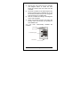
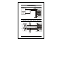
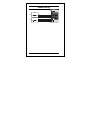
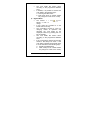
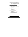
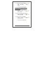
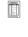
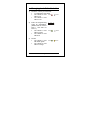
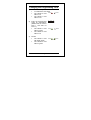
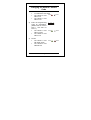
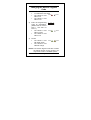
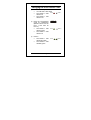
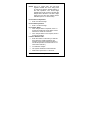
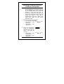
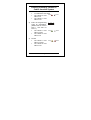
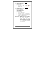
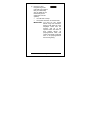
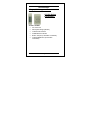
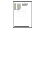
DOOR 2
DOOR 1
1
2
3
4
5
6
7
8
9
0
#
AC-020
Hardware Installation and User’s Guide
03/02
AC-020
Page 2
03/02
Hardware Installation
and User’s Guide for the AC-020
Access Control System
DOOR 2
DOOR 1
AC-020
1
2
3
4
5
6
7
8
9
0
#
Page 3
03/02
Copyright
Information in this document, including URL and
other Internet Web site references, is subject to
change without notice. Unless otherwise noted,
the example companies, organizations, products,
people and events depicted herein are fictitious
and no association with any real company,
organization, product, person or event is intended
or should be inferred.
© Copyright 2000 Rosslare. All rights
reserved.
Rosslare, the Rosslare logo, and the Rosslare
products referred to herein are either the
trademarks or registered to the trademarks of
Rosslare, All other trademarks are the property of
their respective owners.
Software License Agreement.
ROSSLARE IS WILLING TO LICENSE THE
ENCLOSED SOFTWARE ONLY ON THE
CONDITION THAT YOU ACCEPT ALL OF THE
TERMS CONTAINED IN THIS LICENCE
AGREEMENT. This is a legal agreement
between you (either the individual or the end-user
or an entity) and Rosslare. By opening this
software package, you are agreeing to be bound
by the terms and conditions of this Agreement. If
you do not agree to the terms of this Agreement,
promptly return the software package and other
items that are part of this product in their original
AC-020
Page 4
03/02
package with your payment receipt to your point
of purchase for a full refund. Grant of License.
Rosslare and its suppliers grant you a
nonexclusive license to use one copy of the
enclosed software program (”Software”) on one
computer with the Rosslare product you have
purchased. No other rights are granted. The
software is in use if it is loaded on the computer’s
permanent or temporary memory. For backup
purposes only you may make one copy of the
Software. You must include on the backup copy
all copyright and other notices included on the
Software as supplied by Rosslare. Installation on
a Network server for the sole purpose of your
internal distribution of the Software is permitted
only if you have purchased an individual software
package for each networked computer to which
the software is distributed. Restrictions. Rosslare
and its suppliers retain ownership of the
Software. You may not decompile, disassemble,
reverse engineer, or modify the Software in any
way. You may not transmit the software over a
network (except as expressly permitted above),
by telephone, or electrically using any means.
You may not transfer the Software except upon a
permanent transfer of the enclosed Rosslare
product provided that all software updates are
included in the transfer, you do not retain a copy
of the Software, and the transferee agrees to be
bound by the terms and conditions of this license.
Upon any violation of any of the provisions of this
AC-020
Page 5
03/02
Agreement, rights to use the Software shall
automatically terminate and the Software must be
returned to Rosslare or all copies of the Software
destroyed. Limited Product Warranty. Rosslare
warrants
that
any
hardware
products
accompanying this documentation shall be free
from significant defects in material and
workmanship for a period of one year from the
date of purchase. Rosslare also warrants that the
Software accompanying this documentation will
perform substantially in accordance with the
documentation for a period of 90 days from
purchase. Rosslare’s hardware and software
warranty is nontransferable and is limited to the
original purchaser. Product Remedies. Rosslare’s
entire liability and the licensees exclusive remedy
for any breech of warranty, shall be, at Rosslare’s
sole option, either a) return the price paid or b)
repair or replacement of hardware or software,
provided that the hardware is returned to the
point of purchase, with a copy of the sales
receipt. Any replacement hardware and software
will be warranted for the remainder of the original
warrantee period or 30 days for the hardware and
30 days for the software, whichever is longer.
The remedies are void if failure of the software or
hardware has resulted from abuse, accident or
misapplication.
Limitation of Liability.
THE WARRANTIES SET FORTH IN THIS
AGREEMENT
REPLACE
ALL
OTHER
AC-020
Page 6
03/02
WARRANTIES.
ROSSLARE
EXPRESSLY
DISCLAIMS ALL OTHER WARRANTIES,
INCLUDING BUT NOT LIMITED TO, THE
IMPLIED
WARRANTIES
OF
MERCHANTABILITY AND FITNESS FOR A
PARTICULAR
PURPOSE
AND
NONINFRINGEMENT OF THIRD PARTY RIGHTS
WITH RESPECT TO THE DOCUMENTATION,
SOFTWARE,
AND
HARDWARE.
NO
ROSSLARE DEALER, AGENT, OR EMPLOYEE
IS
AUTHORISED
TO
MAKE
ANY
MODIFICATION, EXTENSION, OR ADDITION
TO THIS WARRANTY. IN NO EVENT WILL
ROSSLARE OR IT”S SUPPLIERS BE LIABLE
FOR ANY COSTS OF PROCUREMENT OF
SUBSTITUTE PRODUCTS OR SERVICES,
LOST PROFITS, LOSS OF INFORMATION OR
DATA, OR ANY OTHER SPECIAL DIRECT OR
INDIRECT,
CONSEQUENTIAL,
OR
INCIDENTAL DAMAGES ARISING IN ANYWAY
OUT OF THE SALE, OF, USE OF, OR
INABILITY TO USE ANY ROSSLARE PRODUCT
OR SERVICE, EVEN IF ROSSLARE HAS BEEN
ADVISED OF THE POSSIBILITY OF SUCH
DAMAGES. IN NO CASE SHALL ROSSLARE’S
LIABILITY EXCEED THE ACTUAL MONEY PAID
FOR THE PRODUCTS AT ISSUE. Because
some
jurisdictions
do
not
allow
the
implementation of limited warranties or liability for
incidental, consequential, special, or indirect
damages, the above limitation may not always
AC-020
Page 7
03/02
apply. The above limitations will not apply in case
of personal injury where and to the extent that
applicable law requires such liability.
U.S. Government Restricted Rights.
The software is provided to the U.S. Government
only with restricted rights and limited rights of
use, duplication or disclosure by the U.S.
Government is subject to restrictions set forth in
48 C.F.R 2.101 (Oct 1995) consisting of
“Commercial
Computer
Software”
and
“Commercial Computer Software Documentation”
as such terms are used in 48 C.F.R. 12.212
(September 1995), and in FAR Sections 52-22714 and 52-227-19 or DFARS Section 52.2277013 (C) (ii), or their successors, as applicable.
Consistent with 48. C.F.R. 12.212 and 48 C.F.R.
227.7202-1 through 227.7204-1 (June 1995), or
any successor regulations, this software is
provided to the terms and conditions herein.
Contractor/ Manufacturer Rosslare Enterprises
Ltd. 12 Wang Tai Road, Hong Kong.
AC-020
Page 8
03/02
Contents
Introduction .....................................................11
Key Features .................................................13
Technical Specifications ................................14
Installation .......................................................16
Mounting the Controller .................................16
Power Wiring .................................................19
Typical Lock and Option Wiring .....................19
Reader Wiring................................................20
Features and Concepts...................................21
Modes of Operation .......................................21
Changing the Modes of Operation.................25
Events and Event Actions..............................28
AC-020 Programming Instructions ................31
Programming Menu Quick Reference Guide .31
Replacing a Lost Programming Code ...........58
Replacing a Lost Normal / Secure Code .......59
Accessories .....................................................60
Technical Support...........................................67
AC-020
Page 9
03/02
AC-020
Page 10
03/02
Introduction
The AC-020 is an advanced two door controller,
which allows you to add or delete employees
from the system, change system mode status
and change system authorization codes.
The AC-020 provides a higher level of security as
the programmer is normally placed in a secure
location while the reader sensors are remotely
located outside the controlled premises. Should a
remote sensor be attacked, entry cannot be
gained as the remote sensor only provides data
to the programmer, not authorization to release
the controlled door.
The AC-020 accepts up to 500 employees for
each door via the use of proximity cards
(provided separately) or PIN. Each employee is
issued a unique proximity card or PIN code.
Employees designated 01 to 10 are Master users
and can operate the system in both the Normal
and Secure modes of operation. Employees 11 to
500, when entered from the external reader
sensor may only operate the Controller in the
Normal and Bypass modes of operation.
It is very important to keep an accurate record of
the slot number and its assignment to each
employee. This is to enable you to add additional
employees at a later time or to delete a Prox. or
PIN code if one is lost or stolen. A record form is
AC-020
Page 11
03/02
enclosed for your reference to assist you with
your record keeping.
The AC-020 is capable of learning both PIN
codes (keyboard based codes - 4 digits code)
and Prox. Codes (codes received from proximity
card reader). The Controller has two reader
inputs, one for Door 1 and one for Door 2. These
readers are to be located outside the restricted
area. Readers need to be Wiegand 26 bits
interface type, and may be a Proximity card
reader (for Prox. Codes), Keyboard (for PIN type
codes) or combined PIN/PROX reader. Please
refer to Accessories – page 60.
The PIN reader can be used for programming the
system, in addition to its regular duty of codes
entry. During normal use, PIN codes that are
employee codes can be entered only from reader
sensor, while Special Codes may be entered
either from AC-020 or from the reader.
Topics in this section:
•
Key Features
•
Technical Specifications
AC-020
Page 12
03/02
Key Features
Here are some of the AC-020 system key
features:
• Supports two 26-Bit Wiegand compatible
Readers
•
•
Three Modes of Operation
Normal Mode
Bypass Mode
Secure Mode
Lock Strike Relay Output
•
Request to Exit (REX) button
•
Internal Siren
•
Comes with security screw and security tool
•
Two Status / Programming Interface LED’s
•
Built-in Programming Keypad
•
Battery Charger
•
Bell, Chime, & Strobe annunciator
•
Programmable Lock Strike release time.
•
Built-in Lock Strike suppressor diode.
•
Comes with mounting template for easier
installation.
•
Built-in Reader Power Supply
•
Built-in Lock Strike Power Supply
AC-020
Page 13
03/02
Technical Specifications
Electrical Characteristics
Main Unit
Operating Voltage:
16V AC (1.5A, 25VA)
From a transformer
Maximum Input
Current:
(Not including attached
devices)
Standby: 65mA
Maximum: 120mA
Battery Charger:
12V DC Lead Acid
Battery
Up to 7AH
recommended
Outputs
Lock Strike Relay
Output:
5A Relay
Lock Strike Power
Supply:
12V DC constant
voltage
1.2 A current limit
Reader Power
Supply:
Voltage: 12V DC
Max Current: 300mA
AC-020
Page 14
03/02
Inputs
Request to Exit
(REX):
N.O. Dry Contact
Reader Input:
26-Bit Wiegand
Compatible
Indicators & Annunciators
Visual:
Two Tri-Colored LEDs
Audio:
Built in Sounder (Bell,
Chime & Siren)
Piezoelectric Buzzer
Environmental Characteristics
Operating
Temperature:
-25°F to 145°F (-31°C
to 63°C)
Operating Humidity:
0 to 95% (NonCondensing)
Mechanical Characteristics
Dimensions:
5.3” (134mm) L x 3.4”
(85mm)
W x 1.2” (30mm) D
(Fits US Gang Box)
Weight:
0.5 lbs (220g)
AC-020
Page 15
03/02
Installation
The AC-020 has been designed for easy
installation. Only a few steps are required to
install the controller.
In this section you will learn how to mount the
controller in your desired location.
You will learn how to wire the controller to its
power source, which includes attaching the
controller to a rechargeable Lead Acid battery.
Wiring diagrams are also provided for attaching
the controller to the REX button and External 26Bit Wiegand Compatible readers.
Topics in this section:
•
Mounting the Controller
•
Power Wiring
•
Typical Lock and Option Wiring
•
Reader Wiring
AC-020
Page 16
03/02
Mounting the Controller
1)
2)
3)
Before starting, select the location for
mounting the AC-020 controller. The
controller should be installed indoors and
within the premises to be secured. It is
recommended that the controller be installed
where it cannot be seen for increased
security, but still close enough to the doors
so that the controller’s annunciator (Door
Bell, Chime & Siren) can be heard.
Find the mounting template label that is
provided in your AC-020 packaging, and
place it at the location that you wish to install
the controller. The template is designed to
assist you through the mounting procedure,
showing you where you drill holes in the wall
to pass the wiring through and where the
wall must be drilled to insert the controllers
mounting screws.
(Skip this step when attaching the AC-020 to
a US Gang Box)
Drill a hole for cables as indicated on the
wiring template. Two hole sizes are shown to
allow for the amount of cables needed,
depending on installation requirements or
adding a backup battery. Drill two screw
holes for mounting the AC-020 to the wall.
AC-020
Page 17
03/02
4)
Remove the case screw from the controller
(see diagram below to locate the case
screw) and remove the front case from the
controller.
5) Mount the controller to the wall using the two
screws provided in the Installation Kit or use
the screws provided with your US Gang Box
when mounting to a US Gang Box.
6) Wire the controller according to the diagrams
on the next few pages.
7) Return and secure the front case using the
security screw and security tool provided in
the Installation Kit.
You now have mechanically installed the
controller.
Door 2 LED
Door 1 LED
DOOR 1
3 x 4 Matrix Keypad
DOOR 2
1
2
4
5
3
6
7
8
9
0
#
Case Screw
AC-020
Page 18
03/02
Power Wiring
POWER SUPPLY
FROM
TRANSFORMER
(+)
(-)
16V AC (1.5A, 25VA)
1
12V DC LEAD ACID
BATTERY
UP TO 7 AH
DOOR 2
DOOR 1
(+)
(-)
RECOMMENDED
2
3
4
5
6
7
8
9
0
#
Typical Lock and Option Wiring
N.O.
REX 1
(-)
DOOR 1
N.O.
REX 2
(-)
DOOR 2
AC-020
Page 19
DOOR 1
DOOR 2
1
2
3
4
5
6
7
8
9
0
#
03/02
Reader Wiring
DOOR 1
READER
(-)
DOOR 1
12V DC, Max. 300mA
READER
DOOR 2
12V DC, Max. 300mA
AC-020
(-)
+12V
DO
D1
+12V
DO
D1
(-)
+12V
DO
D1
(-)
+12V
DO
D1
Page 20
DOOR 2
1
2
4
5
6
7
8
9
0
#
3
03/02
Features and Concepts
Now that you have installed your AC-020
controller, it is time to become familiar with its
features and concepts.
In this section you will learn about all the features
that are programmable. They are the basic
features of the AC-020 and can be programmed
directly from the controller’s programming
keypad.
You will learn about the controller’s various
modes of operation, how to switch between the
Modes of Operation, Special Codes, Events and
Event Actions.
Topics in this section:
•
Modes of Operation
•
Changing the Modes of Operation
•
Events and Event Actions
AC-020
Page 21
03/02
Modes of Operation
IMPORTANT NOTE:
• In all of the following operations, in order to
select DOOR 1 press the * key. In order to
select DOOR 2 press the # key.
•
In the following operations, if the operation
is done from an external reader, always
press the # key on the external keyboard.
•
The following examples show the LED
status of Door 1 but are applicable to Door
2 as well.
The AC-020 has three modes of operation
Normal, Bypass, and Secure Mode. The three
modes provide different levels of security.
1) Normal Mode
•
•
•
AC-020
DOOR 2
The DOOR 1 /
GREEN
DOOR 2 LED is
green
In this mode the Controller is in the
normal level of security. Only those
codes that the Controller recognizes will
activate the Lock Strike.
The controller’s keypad is used for
programming, changing modes of
operation, and activating the Lock Strike
using the employee codes.
Page 22
03/02
•
2)
The Lock Strike will remain active
according to the programmed Release
Time.
•
In addition, it is possible to activate the
Lock Strike in the following ways:
a. Pressing the REX button
b. Valid Code (from an outside reader
only using Prox. Code or Pin. Code)
Bypass Mode
•
•
•
•
•
AC-020
DOOR 2
1
The DOOR 1 / DOORORANGE
DOOR 2 LED is
orange
In this mode the Controller is in the
lowest level of security.
The Controller’s keypad is used for
changing modes of operation and
activating the Lock Strike by the
employee codes or by pressing the “*/#”
key accordingly.
The Lock Strike will remain active
according to the programmed Release
Time.
If the Lock Strike is defined as Normally
Closed it will always be active. If the
Lock Strike is defined as Normally Open
it can be activated in the following ways:
a. Pressing the REX button
b. Valid Code (from an outside reader
only using Prox. Code or Pin. Code)
Page 23
03/02
3)
Secure Mode
•
•
•
•
•
AC-020
DOOR 2
The DOOR 1 / DOOR 1 RED
DOOR 2 LED is red
In this mode the Controller is in the
highest level of security.
The Controller’s keypad is used for
changing modes of operation and
activating the Lock Strike by the
employee codes.
The Lock Strike will remain active
according to the programmed Release
Time.
In addition, it is possible to activate the
Lock Strike in the following ways:
a. Pressing the REX button
b. Master Codes (from an outside
reader only using Prox. Code or
Pin. Code)
Page 24
03/02
Changing the Modes of Operation
NOTE: Changing the modes of operation can be
done by entering the correct code into the
Controller’s Programming keypad or the
external reader’s keypad.
Changing from Normal Mode to
Secure Mode
1)
The controller is in Normal Mode
•
2)
DOOR 2
GREEN
Enter your Normal / Secure PIN Code
•
3)
DOOR 1 / DOOR 2
LED is green
DOOR 1 / DOOR 2
LED will flash red
DOOR 2
DOOR 1
RED
Press the “*/#” key, respectively.
•
DOOR 1 / DOOR 2
LED will turn red
•
You are now in Secure Mode
AC-020
Page 25
DOOR 1
DOOR 2
RED
03/02
Changing from Secure Mode to
Normal Mode
1)
The controller is in Secure Mode
•
2)
DOOR 1
DOOR 2
RED
Enter your Normal / Secure PIN Code
•
3)
DOOR 1 / DOOR 2
LED is red
DOOR 1 / DOOR 2
LED will flash green
DOOR 1
DOOR 2
GREEN
Press the “*/#” key, respectively.
•
DOOR 1 / DOOR 2
LED will turn green
•
You are now in Normal Mode
DOOR 1
DOOR 2
GREEN
Changing from Normal Mode to
Bypass Mode
1)
The controller is in Normal Mode
•
2)
DOOR 1 / DOOR 2
LED is green
DOOR 1
DOOR 2
GREEN
Enter your Normal / Bypass PIN Code
•
AC-020
DOOR 1 / DOOR 2
LED
will
flash
orange
Page 26
DOOR 1
DOOR 2
ORANGE
03/02
3)
Press the “*/#” key, respectively.
•
DOOR 1 / DOOR 2
LED
will
turn
orange
•
You are now in Bypass Mode
DOOR 1
DOOR 2
ORANGE
Changing from Bypass Mode to
Normal Mode
1)
The controller is in Bypass Mode
•
2)
DOOR 1
DOOR 2
ORANGE
Enter your Normal / Bypass PIN Code
•
3)
DOOR 1 / DOOR 2
LED is orange
DOOR 1 / DOOR 2
LED will flash green
DOOR 1
DOOR 2
GREEN
Press the “*/#” key, respectively.
•
DOOR 1 / DOOR 2
LED will turn green
•
You are now in Normal Mode
AC-020
Page 27
DOOR 1
DOOR 2
GREEN
03/02
Events and Event Actions
Tamper Event
A Tamper Event is triggered if the controller
detects that a reader has been disconnected or
loses power, and can also be triggered if the case
of the reader is removed.
Possible Tamper Event Actions
Reader sensor wire is disconnected from the AC020 DOOR 1 / DOOR 2 reader input terminal
Tamper data signal is received from DOOR 1 /
DOOR 2 reader sensor
To clear a Tamper Event enter a valid code or
Lock Strike code which will open the door locker
output of the Door that caused the tamper event.
For example, tamper condition at Door 2 during
Secure status, entering Door 2 Lock Strike Code
1 (default 0852) from external reader will not
clear tamper because it is not permitted to open
the door during this operation mode. However,
applying the same code from the AC-020
keyboard will clear tamper output as well as
opening Door 2 Lock Strike and stopping the
siren (assuming no Door 1 tamper).
AC-020
Page 28
03/02
Request to Exit (REX) Button
The REX button must be located inside the
premises to be secured and is used to open the
door without the use of a proximity card or PIN
code, it is usually located in a convenient
location, e.g. Inside the door or at a receptionist’s
desk. The function of the REX button depends on
whether the Lock Strike Relay is programmed for
Fail Safe Operation or Fail Secure Operation.
The door chime in the BLD40 does not sound
when the REX button is used to open the door.
1) Fail Secure Operation: From the moment
the REX button is pressed, the door will be
unlocked until the ”Lock Strike Release
Time” has passed. After this time, the door
will be locked even if the REX button has not
been released.
2) Fail Safe Operation: From the moment the
REX button is pressed, the door will be
unlocked until the REX button is released,
plus the ”Lock Strike Release Time.” In this
case the ”Lock Strike Relay” only begins its
count down once the REX button has been
released.
AC-020
Page 29
03/02
Siren Sound
Siren sound triggered by Door 1 or Door 2 tamper
is generally stopped by clearing the tamper of
that door. However, if the tamper condition at the
other door exists, one is required to clear that
tamper event as well, in order to stop the siren.
Either way, the siren may stop on its own if the
pre-programmed siren time has elapsed.
AC-020
Page 30
03/02
Programming Instructions
After reading Features and Concepts – page 21,
you should already have an understanding of the
AC-020’s features.
Most of these features can be programmed via
the AC-020’s programming keypad. The following
pages describe how to program the AC-020 using
the programming keypad.
Topics in this section:
•
Programming Menu Quick Reference
Guide
•
Programming the AC-020
AC-020
Page 31
03/02
Programming Menu Quick
Reference Guide
Menu
Number
1
2
3
4
5
6
7
8
0
AC-020
Menu
Description
Changing Lock Strike
Code 1
Changing Lock Strike
Code 2
Changing Program Code
Changing Normal/Secure
Code
Changing Normal/Bypass
Code
Changing Door Release
Time
Choosing Fail
Secure/Fail Safe
Operation
Enrolling Proximity Cards
or Keyboard Codes
Deleting Proximity Cards
or Keyboard Codes
Returning to Default
Factory Setting
Page 32
Page
Number
38
40
42
44
46
49
50
51
54
56
03/02
Programming the AC-020
FOR DOOR 1 PROGRAM:
Menu
Number
1
2
3
4
5
6
7
8
0
AC-020
Function
Changing Lock Strike
Code 1
Changing Lock Strike
Code 2
Changing Program Code
Changing
Normal/Secure Code
Changing
Normal/Bypass Code
Changing Door Release
Time
Choosing Fail
Secure/Fail Safe
Operation
Initial
Setting
2580
0000*
1234
3838
0000*
0004
(4
seconds)
Fail
Secure
Enrolling Proximity
Cards or Keyboard
Codes
Deleting Proximity Cards
or Keyboard Codes
Returning to Default
Factory Setting
Page 33
03/02
FOR DOOR 2 PROGRAM:
Menu
Number
1
2
3
4
5
6
Function
Changing Lock Strike
Code 1
Changing Lock Strike
Code 2
Changing Program Code
Changing
Normal/Secure Code
Changing
Normal/Bypass Code
Changing Door Release
Time
Choosing Fail
Secure/Fail Safe
Operation
Initial
Setting
0852
0000*
4321
8383
0000*
0004
(4
seconds)
Fail
Secure
7
Enrolling Proximity
Cards or Keyboard
Codes
8
Deleting Proximity Cards
or Keyboard Codes
0
Returning to Default
Factory Setting
*0000 deletes a function
AC-020
Page 34
03/02
NOTE: You must be in NORMAL mode to
program the AC-020. DOOR 1 / DOOR 2
LED will be green.
Wrong or timed out entries will reset the
controller to the NORMAL mode
condition.
To exit programming, press the “*/#” key
for two seconds. Three beeps are
generated and the system will return to
NORMAL mode. A short press on the
“*/#” key will also return the system to
NORMAL mode, and a long beep will be
heard. This aborts the programming, but
in some cases, such as Program
Function #7, data may have already
been programmed.
Wrong entries during programming may
also abort programming, along with long
beep generation.
All programming operations are done
either from the on-board keyboard or
from the reader. Programming the
PROX. employee codes requires using
proximity reader and proximity cards.
AC-020
Page 35
03/02
Entering Programming Mode
To begin programming the controller’s settings,
the AC-020 must first place into Programming
Mode. You may only enter Programming mode
from Normal mode, the controller does not permit
entry to Programming Mode if the controller is in
Bypass and Secure Mode.
1) Press the “*/#” key for 2 seconds
•
2)
The DOOR 1 LED
will turn red
DOOR 1
DOOR 2
RED
Enter the Programming Code. The factory
default Programming Code is 1234 for Door
1 and 4321 for Door 2.
If the Programming Code is valid the
controller will be in Programming Mode.
•
The DOOR 1 LED
will turn green
DOOR 1
DOOR 2
GREEN
If the Programming Code is NOT valid the
controller will emit a loud beep and will NOT
enter Programming Mode.
AC-020
Page 36
03/02
Exiting Programming Mode
1)
2)
3)
4)
To exit Programming Mode at any time:
Press the “*” or “#” key for 2 seconds. You
will hear 3 beeps and the controller will
return to Normal Operating Mode.
Wrong entries may reset the controller back
to Normal Operating Mode.
While in Programming Mode if no key is
pressed for 30 seconds the AC-020 will emit
a long beep and return to Normal Operating
Mode.
A short press on the “*” or “#” key may also
return the controller to Normal Operating
Mode, accompanied by a long beep.
AC-020
Page 37
03/02
Changing Lock Strike Code 1
1)
Press the “*/#” key for 2 seconds
•
•
•
2)
Enter the Programming
Code for confirmation.
(Default code is 1234 for
Door 1 and 4321 for
Door 2.)
•
•
3)
You will hear a short beep
The DOOR 2 LED DOOR 1 RED
will turn off
The DOOR 1 LED
will turn red
The DOOR 1 LED
will turn green
The DOOR 2 LED
will be off
DOOR 2
? ? ? ?
DOOR 1
DOOR 2
GREEN
Press 1
•
•
AC-020
The DOOR 1 LED
will remain green
The DOOR 2 LED
will turn red
Page 38
DOOR 2
DOOR 1
GREEN
RED
03/02
4)
Enter the new 4-digit
code you wish to set as
Lock Strike Code 1.
•
•
•
AC-020
? ? ? ?
You will hear 3 beeps
The system will return to NORMAL
mode
The default Lock Strike Code 1 is 2580
for Door 1 and 0852 for Door 2
Page 39
03/02
Changing Lock Strike Code 2
1)
Press the “*/#” key for 2 seconds
•
•
•
2)
Enter the Programming
Code for confirmation.
(Default code is 1234 for
Door 1 and 4321 for
Door 2.)
•
•
3)
You will hear a short beep
The DOOR 2 LED DOOR 1 RED
will turn off
The DOOR 1 LED
will turn red
The DOOR 1 LED
will turn green
The DOOR 2 LED
will be off
DOOR 2
? ? ? ?
DOOR 1
DOOR 2
GREEN
Press 2
•
•
AC-020
The DOOR 1 LED
will remain green
The DOOR 2 LED
will turn orange
Page 40
DOOR 1
DOOR 2
GREEN
03/02
4)
Enter the new 4-digit
code you wish to set as
the new Programming
Code.
•
•
? ? ? ?
You will hear 3 beeps
The system will return to Normal mode
NOTE: There is no default code for Lock Strike
Code 2.
AC-020
Page 41
03/02
Changing the Programming Code
1)
Press the “*/#” key for 2 seconds
•
•
•
2)
Enter the Programming
Code for confirmation.
(Default code is 1234 for
Door 1 and 4321 for
Door 2.)
•
•
3)
You will hear a short beep
The DOOR 2 LED DOOR 1 RED
will turn off
The DOOR 1 LED
will turn red
The DOOR 1 LED
will turn green
The DOOR 2 LED
will turn off
DOOR 2
? ? ? ?
DOOR 1
DOOR 2
GREEN
Press 3
•
•
AC-020
The DOOR 1 LED
will remain green
The DOOR 2 LED
will turn green
Page 42
DOOR 1
DOOR 2
GREEN GREEN
03/02
4)
Enter the new 4-digit
code you wish to set as
the new Programming
Code
? ? ? ?
NOTE: Programming Code cannot be erased.
When trying to program code 0000, you
will hear a long beep and the system will
return to Normal operating mode.
AC-020
Page 43
03/02
Changing the Normal / Secure
Code
1)
Press the “*/#” key for 2 seconds
•
•
•
2)
Enter the Programming
Code for confirmation.
(Default code is 1234 for
Door 1 and 4321 for
Door 2.)
•
•
3)
You will hear a short beep
The DOOR 2 LED DOOR 1 RED
will turn off
The DOOR 1 LED
will turn red
The DOOR 1 LED
will turn green
The DOOR 2 LED
will turn off
DOOR 2
? ? ? ?
DOOR 1
DOOR 2
GREEN
Press 4
•
•
AC-020
The DOOR 1 LED
will remain green
The DOOR 2 LED
will flash red
Page 44
DOOR 1
GREEN
DOOR 2
RED
03/02
4)
Enter the new 4-digit
code you wish to set as
the new Normal/Secure
change code.
•
•
AC-020
? ? ? ?
You will hear 3 beeps
The system will return to Normal mode
(Default Secure code is 3838 for Door 1
and 8383 for Door 2.)
Page 45
03/02
Changing the Normal / Bypass
Code
1)
Press the “*/#” key for 2 seconds
•
•
•
2)
Enter the Programming
Code for confirmation.
(Default code is 1234 for
Door 1 and 4321 for
Door 2.)
•
•
3)
You will hear a short beep
The DOOR 2 LED DOOR 1 RED
will turn off
The DOOR 1 LED
will turn red
The DOOR 1 LED
will turn green
The DOOR 2 LED
will turn off
DOOR 2
? ? ? ?
DOOR 1
DOOR 2
GREEN
Press 5
•
•
The DOOR 1 LED
will remain green
The DOOR 2 LED
will flash orange
DOOR 1
DOOR 2
GREEN ORANGE
NOTE: The Normal / Bypass Code also controls
the Chime function for the AC-020. You
may set the code to 4 available options.
AC-020
Page 46
03/02
Option 1: Disabling Bypass Mode - Disabling
the Chime
• Enter 0000. The Bypass Mode and the
Chime function are disabled.
•
You will hear 3 beeps
•
The system will return to Normal mode
Option 2: Disabling Bypass Mode - Enabling
the Chime
• Enter 0001. The Bypass Mode is disabled
and the Chime function is enabled for
Normal mode.
•
You will hear 3 beeps
•
The system will return to Normal mode
Option 3: Enabling Bypass Mode - Disabling
the Chime
• Enter a 4-digit code ending with the digit 0.
The Bypass mode is enabled and the
Chime function is disabled.
•
You will hear 3 beeps
•
The system will return to Normal mode
AC-020
Page 47
03/02
Option 4: Enabling Bypass Mode - Enabling
the Chime
• Enter a 4-digit code ending with any digit
except 0. The Bypass mode and the Chime
function are enabled for both Normal mode
and Bypass mode.
•
You will hear 3 beeps
•
The system will return to Normal mode
NOTE: No default Bypass code exists.
AC-020
Page 48
03/02
Changing the Door Release Time
1)
Press the “*/#” key for 2 seconds
•
•
•
2)
Enter the Programming
Code for confirmation.
(Default code is 1234 for
Door 1 and 4321 for
Door 2.)
•
•
3)
You will hear a short beep
The DOOR 2 LED DOOR 1 RED
will turn off
The DOOR 1 LED
will turn red
The DOOR 1 LED
will turn green
The DOOR 2 LED
will turn off
DOOR 2
? ? ? ?
DOOR 1
DOOR 2
GREEN
Press 6
•
•
AC-020
The DOOR 1 LED
will remain green
The DOOR 2 LED
will flash green
Page 49
DOOR 1
DOOR 2
GREEN GREEN
03/02
NOTE: This is a 4-digit code. The first digit
signifies whether the unit is being used
for fail secure (factory default setting) or
fail safe operation. The second digit
signifies the length of time in minutes the
tamper alarm will sound. The last 2 digits
signify the time the door release will be
activated (from 01 to 99 seconds).
For Fail Secure Operation:
• Enter 0 for the first digit
For Fail Safe Operation:
• Enter 1 for the first digit
For Tamper Alarm:
• If the Tamper Alarm is required, enter 1-9
as the second digit to set the alarm sound
time from a minute to 9 minutes.
•
If the Tamper Alarm is not required, enter 0
as the second digit.
For Door Release Time:
• Enter the number of seconds you wish the
door release to remain activated. (For
example, 0512 means fail secure with a 5minute tamper alarm sound time and a 12
second door release.)
•
You will hear 3 beeps.
•
The system will return to Normal mode.
•
Default door open time is 4 seconds.
AC-020
Page 50
03/02
Enrolling Proximity Cards/Pin
Codes into the System
NOTE: Each proximity card is unique and can
only be assigned to one slot at a time. If
an unassigned proximity card is enrolled
at an occupied slot, the AC-020 will
generate a long beep and wait for
another slot number to be entered. The
card at the current slot location must be
erased first, before a new code is
programmed on that slot number. The
same rules apply for PIN based
employee codes.
1) Press the “*/#” key for 2 seconds
•
You will hear a short beep
DOOR 2
•
The DOOR 2 LED DOOR 1 RED
will turn off
•
The DOOR 1 LED
will turn red
2)
Enter the Programming
Code for confirmation.
(Default code is 1234 for
Door 1 and 4321 for
Door 2.)
•
The DOOR 1 LED
will turn green
•
The DOOR 2 LED
will turn off
AC-020
Page 51
? ? ? ?
DOOR 1
DOOR 2
GREEN
03/02
3)
Press 7
•
•
4)
Enter the 3-digit slot
code you wish to assign
to the employee (for
example,
003
represents slot “3”).
•
•
5)
The DOOR 2 LED
will turn green
The DOOR 1 LED
will turn orange
The DOOR 1 LED
will remain orange
The DOOR 2 LED
will flash green
DOOR 1
DOOR 2
ORANGE GREEN
? ? ? ?
DOOR 1
DOOR 2
ORANGE GREEN
Enroll the proximity card designated for this
slot number to the reader.
•
The DOOR 2 LED will stop flashing
OR,
•
6)
Enter the 4-digit PIN code designated
for this slot number
•
The DOOR 2 LED will stop flashing
To enroll another card, enter the 3-digit slot
code you wish to assign to the next
employee.
•
The DOOR 2 LED will start flashing
AC-020
Page 52
03/02
7)
8)
Present the proximity card designated for
this slot number to the reader.
•
The DOOR 2 LED will stop flashing
OR,
•
Enter the 4-digit keyboard based
employee code designated for this slot
number to the reader
•
The DOOR 2 LED will stop flashing
Continue enrolling cards or entering
keyboard employee codes in this manner
until all employee codes are entered.
NOTE: The AC-020 programmer will not
accept employee codes that are
already allocated to a slot. The AC020 will signal this with a long beep
and the DOOR 2 LED will continue
to flash green.
When finished enrolling the employee codes,
press the “*” or “#” key.
•
You will hear a long beep
•
The AC-020 will return to Normal mode
NOTE: If the programming period times out
before you press the “*” or “#” key,
the controller will emit a long beep
and return to Normal mode.
However, any enrolled employee
codes in this period will remain valid.
AC-020
Page 53
03/02
Deleting Proximity Cards/Pin
Codes from the System
1)
Press the “*/#” key for 2 seconds
•
•
•
2)
Enter the Programming
Code for confirmation.
(Default code is 1234 for
Door 1 and 4321 for
Door 2.)
•
•
3)
You will hear a short beep
The DOOR 2 LED DOOR 1 RED
will turn off
The DOOR 1 LED
will turn red
The DOOR 1 LED
will turn green
The DOOR 2 LED
will turn off
DOOR 2
? ? ? ?
DOOR 1
DOOR 2
GREEN
Press 8
•
•
AC-020
The DOOR 1 LED
will turn orange
The DOOR 2 LED
will turn red
Page 54
DOOR 2
DOOR 1
ORANGE
RED
03/02
4)
Enter the 3-digit slot
code you wish to delete
from the system
•
5)
The DOOR 2 LED
will flash red
Enter the 4-digit
Programming Code (this
last step confirms that
you intentionally want to
delete an employee
from the system).
•
•
•
DOOR 1
ORANGE
DOOR 2
RED
? ? ? ?
You will hear 3 beeps
The system will return to Normal mode
If additional employee codes need to be
deleted, then repeat steps 1-5.
IMPORTANT:
AC-020
? ? ?
Ensure that your record of
employees and their assigned
slot numbers are stored in a
secure location. Then, if you
wish to delete a lost or stolen
employee code from the system,
you can identify the card number
from your record.
Page 55
03/02
Return to Factory Default Settings
1)
Press the “*/#” key for 2 seconds
•
•
•
2)
Enter the Programming
Code for confirmation.
(Default code is 1234 for
Door 1 and 4321 for
Door 2.)
•
•
3)
You will hear a short beep
The DOOR 2 LED DOOR 1 RED
will turn off
The DOOR 1 LED
will turn red
The DOOR 1 LED
will turn green
The DOOR 2 LED
will turn off
DOOR 2
? ? ? ?
DOOR 1
DOOR 2
GREEN
Press 0
•
•
AC-020
The DOOR 1 LED
will flash red
The DOOR 2 LED
will flash red
Page 56
DOOR 2
DOOR 1
RED
RED
03/02
4)
Enter the 4-digit
Programming Code.
(This last step confirms
that you intentionally
want to delete all your
initial settings and
employees from the
system!)
•
•
? ? ? ?
You will hear 3 beeps
The system will return to Normal mode
IMPORTANT: You must be very careful
before using this command.
Doing so will erase all of the
employee codes from the
memory and all of the
special codes will return to
their default values. All
preprogrammed cards, PIN
codes and special codes will
have to be preprogrammed
from the beginning.
AC-020
Page 57
03/02
Replacing a Lost Programming
Code
In the event that your Programming Code is lost,
complete the following procedure to enter
Programming Mode so that you may create a
new Programming Code.
The AC-020 must be in Normal Mode otherwise
this will not work.
Make sure that the DOOR 1 / DOOR 2 LED is
green before proceeding.
1) Disconnect power from the AC-020
2) Press the appropriate REX button
3) Reconnect power to the unit with the REX
button pressed
4) Release the REX button
You now have 20 seconds to program a new
Programming Code into the controller using the
initial default code, 1234 for Door 1 or 4321 for
Door 2, before the controller reverts to the
existing code.
AC-020
Page 58
03/02
Replacing a Lost Normal / Secure
Code
In the event that your Normal / Secure Code is
lost and you are locked in Secure Mode,
complete the following procedure to re-enter
Normal Mode so that you may program a new
Normal / Secure Code.
The AC-020 must be in Secure Mode otherwise
this will not work.
Make sure that the DOOR 1 / DOOR 2 LED is red
before proceeding.
1) Disconnect power from the AC-020
2) Press the appropriate REX button
3) Reconnect power to the unit with the REX
button pressed
4) Release the REX button
You now have 20 seconds to enter the default
Secure Code, 3838 for Door 1 or 8383 for Door 2,
to re-enter into Normal Mode.
AC-020
Page 59
03/02
Accessories
Wiegand 26 Integrated Door
Controllers
AY-X09 Series
PIN Readers
AY-C09 / AY-D09
• For indoor use
•
Slim Stylish Design (Mullion)
•
Includes LED Indicator
•
Audible Buzzer Indicator
•
Built in Tamper (w/ Rosslare Controllers)
•
Includes Bell Button (w/ Rosslare
Controllers)
AC-020
Page 60
03/02
AY-X11 Series
Prox Readers
w/ Bell
AY-C11 / AY-D11
• Reading Distance: 8 to 10cm
•
RF Modulation: ASK at 125 kHz
•
For indoor use
•
Slim Stylish Design (USA Gang Box)
•
Bi-Color Light Indicator
•
Audible Buzzer Indicator
•
Built in Tamper (w/ Rosslare Controllers)
•
Includes Bell Button (w/ Rosslare
Controllers)
AC-020
Page 61
03/02
AY-X12 Series
Prox Readers
AY-C11 / AY-D11
• Reading Distance: 8 to 10cm
•
RF Modulation: ASK at 125 kHz
•
For indoor use
•
Slim Stylish Design (USA Gang Box)
•
Bi-Color Light Indicator
•
Audible Buzzer Indicator (w/ Rosslare
Controllers)
•
Built in Tamper (w/ Rosslare Controllers)
AC-020
Page 62
03/02
AY-X12
Series
Prox
Readers
AY-H12 / AY-J12 / AY-K12 / AY-L12 / AY-M12
• Reading Distance: 7 to 12cm
•
RF Modulation: ASK at 125 kHz
•
For outdoor use
•
Slim Stylish Design (UK or USA Gang Box,
Mullion)
•
Bi-Color Light Indicator
•
Includes LED Control Input
•
Audible Buzzer Indicator
•
Built in Tamper Output
AC-020
Page 63
03/02
AY-X19 Series
Pin & Prox
Readers
AY-C19 / AY-D19
• Reading Distance: 8 to 10cm
•
RF Modulation: ASK at 125 kHz
•
For indoor use
•
Slim Stylish Design (USA Gang Box)
•
Bi-Color Light Indicator
•
Audible Buzzer Indicator
•
Built in Tamper (w/ Rosslare Controllers)
•
Includes Bell Button (w/ Rossalare
Controllers)
AC-020
Page 64
03/02
AY-L23 RF
Reader
AY-L23
• Read Range: 70 meters (200 feet)
•
For Outdoor Use (Water Proof)
•
Frequency: 433MHz
•
Slim Stylish Design (Mullion)
•
Bi-Color LED Indicator
•
LED Control
•
Audible Buzzer Indicator
•
Size: 145mm x 43mm x 20mm
•
Used with SA-26 Wireless Remote
AC-020
Page 65
03/02
AC-020
Page 66
03/02
Technical Support
International Web Site:
http:///www.rosslare.com.hk/support/
Asia, Australia, & South America:
Rosslare Enterprises Ltd.
905-912 Wing Fat Industrial Bldg.,
12 Wang Tai Road, Kowloon Bay
Hong Kong
Tel:
(852) 2795 5630
Fax:
(852) 2795 1508
E-mail:
[email protected]
Europe, Russia, Middle East, Africa:
Rosslare Security Products S.r.l
Via F.lli Gabba 5, 20121 Milano, Italy
Tel:
(39) 0382 24800
Fax:
(39) 0382 24800
E-mail:
[email protected]
[email protected]
United States and Canada:
Rosslare NAPDC
200 East Howard Street, Suite 238,
Des Plaines, IL 60018
USA
Tel:
(847) 827 6330
Fax:
(847) 827 6433
E-mail:
[email protected]
AC-020
Page 67
03/02
9J-IDR-029 / 0706-0820029-00
www.rosslare.com.hk