1
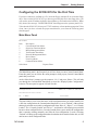
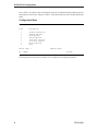
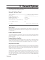
SCON-3074
Configuration
P/N
707112-001
ISSUE/REVISION SCHEDULE
Comments
Initial Release
ii
Rev. No.
Date
707112-001
5/15/2006
707112-001
Where to go for the information you seek.
Several books make up the SCON and LINCS library, and include information to install,
customize, operate, and maintain the SCON-3074 products. Following is a list and
description of these manuals.
SCON-25L/28L/3074 Console Concentrator
1174-25S Communications Server Hardware Reference
The Hardware Description manual provides a description of the hardware found in the
SCON-3074 and other hardware platforms. This manual includes installation planning
considerations and front panel operations.
LINCS Features
The LINCS Feature manual provides a much more detailed description of many of the
LINCS features, including many features not supported on the SCON-3074. Among those
features described in detail are APPN Network Node, SNA PU Gateway support, IPX
Routing, Host Connectivity, 3270 Server capabilities (IPX and TN3270), CUT Device
features including Windowing, Keystroke Record/Playback, Entry Assist and Calculator,
IP routing, IP Channel Bridge, ASCII Device and ASCII Host support, and NetView features.
SCON-3074 Configuration
A Description of the SCON-3074 Configuration process, as well as details of the configuration
panels used to customize the SCON-3074 software can be found in this manual.
LINCS Central Control
This manual contains information about the online Central Control panels. The Central
Control mode provides a means to manage the LINCS software and the SCON-3074
hardware. A detailed description of their use is included in the manual.
LINCS Problem Determination
The LINCS Problem Determination manual aids the LINCS administrator by providing
useful information about error codes and how to interpret them. Information is also included
for running offline utilities.
SCON-20L/22L/25L/28L/3074 Console Concentrator
Planning and Installation Guide
This manual contains information and worksheets to help in the planning for your
installation. Additional information on the configuration, installation, and bring-up of your
SCON is also provided.
707112-001
iii
Table of Contents
1. Getting Started ............................................................................................... 1
Configuring From a Telnet Client............................................................... 1
Using Central Control Mode ...................................................................... 3
Boards in the System .................................................................................. 4
Keys for Configuration ............................................................................... 5
Configuring the SCON-3074 for the First Time ......................................... 5
2. General Options ............................................................................................. 7
General Options Panel ................................................................................ 7
3270 LU Number Display .......................................................................... 8
3. Line Options ................................................................................................... 9
Line Options/ESX Panel ............................................................................. 9
Line Options, TCP/IP Options Panel .......................................................... 12
TCP/IP Options Panel ................................................................................. 14
4. Host Circuits ................................................................................................... 17
3270 Host Circuit Panel .............................................................................. 17
3270 Host Classes Panel ............................................................................. 18
5. TN3270 Client Definition Panel ..................................................................... 21
TN3270 Client Definition Panel ................................................................. 22
The Nickname File ..................................................................................... 26
6. Device Options ............................................................................................... 29
Device Options/General Panel .................................................................... 29
7. Configuration Complete ................................................................................. 31
Configuration Complete Panel ................................................................... 31
Apply Configuration Changes Panel .......................................................... 31
TN3270 Client Definitions ......................................................................... 32
TN3270 Password ...................................................................................... 32
IML Time Panel .......................................................................................... 32
What to do if Your Configuration Will Not Boot ....................................... 33
8. Configuration Backups ................................................................................... 35
Creating a Backup Using the Configuration Utility ................................... 35
Creating a Configuration Backup Using Media Management ................... 35
Creating a Configuration Backup Using FTP ............................................. 36
Creating a Configuration Backup Using eManager ................................... 36
Appendix A. RPQs ............................................................................................. 37
RPQs Panel ................................................................................................. 37
707112-001
v
1. Getting Started
The SCON-3074 provides mainframe console support for up to 96 LPARs and 256 sessions.
Mainframe attachment is by way of one or two ESCON interfaces, each providing support
for up to 48 LPARs and 128 sessions each. Client connections are handled by two 10/100
Mbps Ethernet interfaces. Client traffic may be split across the two Ethernet interfaces in
any way desired.
Although the LINCS operating system has been pre-installed on the hard drive of your
SCON-3074, it must be configured for your environment before you can operate it for the
first time. The initial configuration, as well as subsequent changes, are made through a Telnet
client connection. Configuration changes generally take affect following an IML (Initial
Microcode Load) of the SCON-3074. IMLs can be done immediately after making the changes,
or scheduled to occur at a later time.
For security reasons, it is recommended that you configure a Supervisor Password initially to
disallow unauthorized access to the configuration process.
This section explains some basic concepts about the LINCS operating system and Central Control
mode that will help you in configuring the SCON-3074; how to use Central Control mode, how
to identify the boards in your SCON-3074, and presents the Product Definition Panel.
Once you have completed a working configuration, it is important to back your configuration
up for disaster recovery purposes.
Configuring From a Telnet Client
To configure the SCON-3074 from a Telnet client you must initially have a configured network
interface. Information needed to configure the Telnet interface may be entered through an
ASCII text file ‘acc$data.sys’, loaded into the floppy drive. The SCON-3074 will look for the
existence of this file at IML time searching first the floppy drive, then the hard drive. A
default acc$data.sys file ships on the hard drive and contains the following data:
Lineid=FET1
IP=192.168.0.74
TCP=23
Router=
Subnet=255.255.255.0
Mac=
Password=
You may force your own values by creating your own file and placing it in the floppy drive.
During the boot, information from the acc$data.sys file will be used to configure the Telnet interface.
After initially booting up, you can make changes to this file directly through use of FTP (to
the hard drive) or by inserting a new file into the floppy drive, and copying it to the hard drive.
The information is contained in the file in the form of parameter equates. Not all parameters
are required. You must however, include the LINEID, IP, and TCP parameters as a minimum.
The LINEID parameter refers to the name of the network interface card used in the SCON-3074,
707112-001
1
SCON-3074 Configuration
and may reference either ‘FET1’ or ‘FET2’. Looking from the back of the SCON-3074,
FET1 is always the leftmost of the two Ethernet cards.
The IP parameter of course refers to the IP address that is being assigned to the SCON. The
SCON does not make use of DHCP, and must therefore be assigned a real IP address.
The TCP parameter refers to the TCP port to be used for the Telnet connection. Although you
can use the default TCP port for Telnet (not recommended for security reasons), you must
define which port you intend to use (port 23 is not assumed). The port number that you select
for use by the Telnet client can not be the same port used to support any TN3270 clients that
may be configured.
The router parameter is not needed if your client is to be located on the same subnet as the
SCON, and represents the IP address of the default router (or gateway) that is to be used to
provide network access from other subnets. The router address used must be on the same
subnet as the address assigned to the SCON-3074.
You do not need the subnet parameter unless other than default subnet masking is being used.
LINCS assumes the default subnet mask if the parameter is not coded, but will update itself
from information provided by a configured router through an ICMP exchange.
You can omit the mac parameter if the default (burned in hardware) MAC address is being
used (recommended). If the value of the MAC address is changed and put into affect through
an IML, you may have to purge the cache of the default router/switch so that it will ‘forget’
the IP/MAC mapping it may have already cached.
The password parameter is provided for security purposes.
Furthermore, the order of the parameters is not important in the file. The file is not case
sensitive. Parameters that are not used can be omitted. Do not leave any white space in the file
(spaces or blank lines). White space will be interpreted as the end of the file.
If the information is to be entered from floppy, the file should be placed on a floppy and
inserted into the floppy drive, prior to booting the SCON-2XL.
You may use the VT3270 client provided on the CD shipped with the SCON-3074 to connect
to the Telnet interface, or you may use another Telnet client if desired. The VT3270 client
provides a good 3270 terminal emulation, eliminating the need to map most 3270 functions.
If you elect to use a VT100 emulation instead (such as the one that is included in Windows),
some keyboard mapping is used by the SCON-3074 to provide 3270 key functionality. Among
the more commonly used key definitions supported by VT100 and most Telnet terminal
emulations are:
PF1-PF9 = <ESC><1> - <ESC><9>
PF10 = <ESC><0>
PF11 = <ESC> <->
PF12 = <ESC> <=>
Keyboard Reset = <CTRL><R>
Test Mode Toggle = <ESC> <t>
Toggle between status row and 24th row (for most Telnet emulations) = <ESC><?>
You may find a complete listing of Telnet emulations supported by the SCON-3074, in the
LINCS Features manual.
2
707112-001
Chapter 1. Getting Started
Using Central Control Mode
There are three types of panels you will see throughout Central Control. They are:
• Menu Panels - The menu and submenu panels allow you to select which options to
customize, either by menu selection or direct path selection. Some menu selections may
also accept an optional update parameter.
• Data Entry Panels - Data entry panels are used to select specific options. Some fields
require you to enter data, while others allow you to press the Enter key to toggle forward
through a set of choices, or to press Alt + Enter to toggle backward through the choices.
• Information Panels - Information panels display instructions, status information, or
warnings. Messages about the status of the configuration, for example, are displayed on
information panels.
You may use PF keys to move from panel to panel. To find out what the PF keys do, see the
descriptions of PF keys for that series of panels (usually displayed in the 24th row of the
display). The 24th row may not automatically display with some telnet emulations. It does
with VT3270.
Please remember that this document often represent the panels as closely as possible. But the
actual content of the panel and flow between panels is not always the same as the panels
content and panel flow you would see during configuration, particularly if you are running a
code version other than the one represented in the panel.
Menu selection
When any Central Control mode menu is displayed, enter the desired item number at the
‘Select item:’ prompt , then press the Enter key. If an item has input parameters (refer to
individual item descriptions), these are entered following the item select character, using a
comma to separate item parameters.
Direct Path Selection
Some items display submenus that provide further item selections. If submenu selections are
known, direct pathing may be used to execute the item. All items are separated by a forward
slash ( / ) with a comma following the final item selection to separate any input parameters.
All item parameters are separated by commas.
For example, entering “Select Item: 6/4,u” displays the device connections panel, and allows
updates.
If the first character input at the Select Item prompt is a slash ( / ), input will be parsed as if the
Main menu is being displayed. For example, if the Vital Product Data menu is being displayed
on the screen, /6/2 can be entered at the Select Item prompt (Select Item: /6/2) to select the
Display Device Status item from the Main menu.
Optional Update Parameter
Some menu items allow an optional update, denoted by ‘,u’ after the item number on the
menu. Updates require the supervisory password, so after entering ‘item,u’, the password
prompt (Enter Password: ) will be displayed above the Select Item: prompt. Entering the
correct password and pressing Enter will execute the selected item.
707112-001
3
SCON-3074 Configuration
For example, from the Central Control menu, ‘6/4,u’ can be entered to take you into the
device connections panel, and allow you to disconnect a client. If the test input is specified as
6/4 the password prompt will not be displayed and no forced disconnection will be allowed.
If an incorrect password is entered, “ X-f “ is displayed in the input inhibit area of the status
row. After pressing the Reset key, the password may be re-entered, and a new menu item may
be selected.
If no supervisory password was established during configuration, the password prompt will
not be displayed, and updates may be performed without the password.
The supervisory password is defined and set on the General Options panel of Configuration.
Boards in the System
The SCON-3074 supports boards that provide host and client connections. Boards supported
by the 2XL are:
• ESX – ESCON Host Interface
• FET – Fast Ethernet 100/10 Mbps
Board Number and Connector Numbering
Since it is possible to support multiple boards of the same type, the following format was
devised to identify specific connections to the SCON-3074:
brd#.con where:
brd represents the 3 character board mnemonic (FET or ESX) described above.
# represents a number 1-2, identifying the instance of the board that you are referring to.
Examples:
ESX1
FET2
(first ESCON interface card)
(second FET board)
Keys for Configuration
The following PF key descriptions apply to most of the Configuration panels. Some panels
have special keys which will be described in the section for that panel.
• PF1 - Menu – This PF key moves configuration processing back to the previous menu.
This key is available on all configuration panels, and may be used to back out.
• PF7 - Back – Pressing PF7 moves you to the previously displayed panel.
• PF8 - Forw – Pressing PF8 moves you to the next panel.
• PF9 - Default – Assign default values to the fields in the current panel.
• PF10 - Done – This signals the end of the configuration process. It will bring you to the
Configuration Complete panel.
• Enter – These keys toggle through available options, when the cursor is on a field with
multiple options.
4
707112-001
Chapter 1. Getting Started
Configuring the SCON-3074 for the First Time
If you have created an ‘acc$data.sys’ file, insert the floppy with this file on it into the floppy
drive. Power on the SCON-3074. If you have not provided this file in the floppy drive, you
will need to use the IP address defined in the acc$data.sys file found on the hard drive. When
fully booted, the message ‘CONFIGURATION’ should appear on the operator panel LCD.
Telnet into the SCON-3074 from your VT3270 emulator, or from another appropriate Telnet
client. Once you have selected the proper emulation for your client the following panel
should appear.
Main Menu Panel
Main Menu
Item
1
2
3
4
5
6
7
8
Description
Customization Data Menu
Supervisor Functions Menu
Media Management Menu
Vital Product Data Menu
Network Management Menu
Device Menu
Event Log Menu
Communications Menu
Select Item:
Depress Enter
The Main Menu panel is the first panel you will see when you enter Central Control Mode.
From this panel you can follow the menu prompts to bring up any Central Control Mode
panel that you need to.
At the “Select Item:” prompt, type the sequence “1/1,u” and press <Enter>. This will take
you through the Customization Data Menu to select the “Display/Update Configuration”
selection. The next panel to appear will look like this:
Configuration
Customization Data Source:
PF:
1-Menu
LINCS C8.2 Central Control
Default
10-Process
This panel allows you to select the source of the configuration that you wish to modify. For
a first time configuration, the Customization Data Source is set to “Default”. Other options
that may be selected are to read in a configuration file from “Drive A”, “Drive C”, or “Currently
Loaded”. The “Currently Loaded” and “Drive C” would not be valid offerings on a unit that
has never been configured before. Currently Loaded allows you to modify the configuration
that is currently running (normally used after the first configuration is saved). Selecting
“Default” will bring up the configuration based on the hardware installed in the unit, as if the
unit has never been configured before.
707112-001
5
SCON-3074 Configuration
Press <PF10> to continue into configuration. From the Configuration Menu (Submenu List)
shown below select item 1 and press <Enter>. This should take you to the Product Definition
panel.
Configuration Menu
Configuration Menu
Item
1
2
3
4
5
6
7
8
Description
Product Definition
General Options
Line Options
TCP/IP Options
3270 Host Circuits
3270 Host Classes
Device Options
RPQs
Select Item: 1
PF: 1-Menu
LINCS C8.2 Central Control
Depress Enter
10-Done
Selecting the first item in the list allows you to configure all configuration panels.
6
707112-001
2. General Options
Proceeding forward through the configuration panels from the Product Description panels,
you next encounter the General Options panels.
General Options Panel
General Options
Node Name:
Product Assistance Data:
Unique Machine Identifier:
Supervisor Password:
Machine Check Options:
LCD Message when all Comm Links Okay:
LINCS C8.2 Central Control
________________________
__________________________________
_______
PASSWORD
Dump and IML
3074-001
3270 LU Number Display:
Hex
PF: 1-Menu
7-Back 8-Forw 9-Default 10-Done
Node Name
This field defines a unique name for this LINCS node. (Note that this is not the node name
information returned by SNMP. That information is configured on the TCP/IP Options panel
as ‘System Name’.)
Product Assistance Data
This field may contain up to 48 characters. You can use it to record the name and telephone
number of the person to contact for Customer Service. (Note that this information is not
provided to SNMP.)
Unique Machine Identifier
It is recommended that you use the hardware model’s serial number as the unique machine
identifier. If the serial number is not available or you prefer not to use it, you may enter your
own unique 7 character machine identifier. Valid characters include A-Z, 0-9, or spaces.
Supervisor Password
This field contains up to eight alphanumeric characters. It is used for supervisor functions in
LINCS Central Control, such as executing the Configuration Utility and performing Media
Management functions. This password is also used as the FTP password if any of the network
interfaces are configured for IP protocol.
When the SCON-3074 has been IMLed with a default configuration (such as the first time
the SCON-3074 is IMLed, or if the Config key is pressed at state 500), there will not be a
supervisor password defined. You may also choose not to define a password. If no password
is in effect, ANY user may enter the password-protected utilities. Using a password is
strongly recommended.
707112-001
7
SCON-3074 Configuration
If the Configuration utility is entered for display purposes only (i.e., not entered for update),
then the supervisor password will not be displayed. If entered in update mode, then the password
will be displayed, and can be updated.
Machine Check Options
This field determines what LINCS will do if a machine check condition occurs. Options are:
• Dump and No IML (default) - Dump data will be written to the disk, but LINCS will
not re-IML.
• Dump and IML - Dump data will be written to the disk, and then LINCS will re-IML.
• No Dump and No IML - LINCS takes no action.
• No Dump and IML - LINCS simply re-IMLs.
It is recommended that you select the Dump and IML option in most cases.
The LINCS Operating System will dump to the hard drive C. Up to 8 dumps may reside on
the hard drive at on time, each in a separate dump directory. You can copy the dump files to
diskette(s) using the Copy Data Objects utility on the Media Management menu in Central
Control Mode, or FTP the dumps off through the network interface.
LCD Message When All Comm Links Okay
This message displays when the SCON-3074 is powered up and all configured communications
interfaces are communicating as they should. You may change this message to display some
other message. Up to 16 characters may be entered. Example: ‘SCON-3074 OK’
3270 LU Number Display
This field has the following toggle options:
• Hex - This is the default option. If selected, 3270 LU numbers will be displayed in
hexadecimal format throughout all Central Control Utilities. This option is recommended
when configuring the SCON-3074 platform.
• Decimal - 3270 LU numbers will be displayed in decimal format throughout all Central
Control Utilities.
8
707112-001
3. Line Options
A Line Options panel is displayed for each communication board assigned on the Product
Description panel. During configuration, you must enable the protocol for each line on a
particular board. The board types and the protocols they support are listed below:
• ESX - ESCON/Non-SNA Console
• FET - TCP/IP
Line Options/ESX Panel
The Line Options/ESX panel is used to define the connections to the host CPU(s). One such
panel is defined for each CNTLUNIT macro (to each LPAR that it covers) assigned to this
SCON-3074.
Line Options/ESX1
CU Index:
Protocol:
Device Low (Lowest IODEVICE UNITADD):
Device High (Highest IODEVICE UNITADD):
CHANNEL PATH FILTER
LPAR Number (Partition Number):
Source Link Address:
CU Number (CUADD):
LINCS C8.2 Central Control
0
Non-SNA with Channel Path Filter
A0
AF
0
FF
0
(Hot Session 00 corresponds
to Device Low)
HOT SESSION SELECTION MATRIX
0
1
2
3
01234567890123456789012345678901
---------------------------------
Hot Sessions:
Shared Sessions:
00000000000000000000000000000000
00000000000000000000000000000000
PF: 1-Menu
4-Add 5-Delete
7-Back 8-Forw 9-Default 10-Done
The following options are configurable for the ESX board.
CU Index
This option identifies which of the 48 (00-4F) Control Unit Images supported by the ESX are
being configured for this interface. By default, CU 0 is offered. You can change the interface
number by toggling the value of “0”. You can enable additional images by pressing the <PF4>
key. Each CU image must be dedicated to a single LPAR on the host. The maximum number of
CU definitions supported by the SCON-3074 is determined by the number of ESCON interfaces.
The SCON-3074 comes standard with support for up to 48 CU through each ESX interface.
Protocol
The only supported protocol on the SCON-3074 for the ESX card is Non-SNA with Channel
Path Filtering. For support of SNA, APPN, or IP over the ESCON interface, other Visara
Communication Servers may be used (1174 Product Series). If you leave the selection to
707112-001
9
SCON-3074 Configuration
None, the SCON-2XL will treat the interface as if it does not exist.
Device Low and Device High
The value for the Device Low and Device High parameters identify the low end and high end
for a range of addresses supported by this CU. The value of the Device Low number is given
in hex, and can be anywhere in the range of 00-FF. The Device High number must be within
hex 1F of the value of the Device Low parameter and must be equal to or larger than the
Device Low value. The range defined by the Device Low and Device High parameters may
define up to 32 consecutive addresses, and must fall in the range of addresses defined by the
‘UNITADD’ parameter in the ‘CNTLUNIT’ macro of the corresponding Host GEN. To support
more than 32 addresses, make additional CU definitions.
Only configure the SCON-3074 for addresses that have been defined by IO Device Statements
in the GEN on the host. Configuring addresses that have not been defined or that have been
defined for use by another controller may result in serious performance degradation or errors.
LPAR Number
The LPAR Number parameter corresponds to the LPAR number assigned in the PARTITION
parameter of the RESOURCE macro, associated with this connection, in the host’s IOCDS
definition.
Source Link Address
The Source Link Address refers to the ESCON Director port number (2 digit hex) that is
connected back to the mainframe. If an ESCON Director is not used (the SCON-3074 is
directly connected to a port on the mainframe), leave the default value of FF, or assign the
value as 01.
CU Number
This must correspond to the value of the CUADD parameter of the CNTLUNIT macro of the
host’s IOCDS definition, corresponding to this configuration.
Hot Sessions
Hot Console Sessions give you the ability to create a console session that will appear to be
powered on to the LPAR for as long as the SCON-3074 is online. This may be convenient for
situations where it is desired to have a console session that can be accessed across a network
connection by either one person or by multiple persons. Since the console device always
appears to be powered on, it should not be necessary to vary the console active when
establishing a new connection to the session, as long as the SCON-3074 was active when the
LPAR came up. It should be understood that a hot session will not roll to a backup as long as
the SCON-3074 is communicating.
Each of the 32 sessions that may be associated with a single CU definition, can be configured
to be hot. Hot sessions are identified as such, by changing the value from ‘0’ in the appropriate
column. Definitions for the values to enter are:
0 = Not defined to be a hot session
1 = Hot Session (Mod 2 with Extended Data Stream Support)
2 = Hot Session (Mod 2 with Extended Data Stream Support)
10
707112-001
Chapter 3. Line Options
3 = Hot Session (Mod 3 with Extended Data Stream Support)
4 = Hot Session (Mod 4 with Extended Data Stream Support)
5 = Hot Session (Mod 5 with Extended Data Stream Support)
6 = Hot Session (Mod 2 with No Extended Data Stream Support)
7 = Hot Session (Mod 3 with No Extended Data Stream Support)
8 = Hot Session (Mod 4 with No Extended Data Steam Support)
9 = Hot Session (Mod 5 with No Extended Data Stream Support)
The leftmost column corresponds to the Device Low address, defined above. All device
addressing on subsequent panels are referenced from this offset of ‘00’.
Note that only the console sessions should be configured as hot (not the normal VTAM
sessions).
Shared Sessions
Shared Sessions allows two or more TN3270 clients to share the same console session. Up to
twenty-four TN3270 users can be configured to share the same session. Coax and Telnet
clients are not allowed to share the session. Only console sessions can be shared. VTAM
applications will not function correctly when configured as shared. All TN3270 clients sharing
the same session should be configured for the same MOD size and should have the same
Color and Extended Attribute support (the first user to connect sets the standard for the session).
For shared sessions that are also hot, the MOD size will be defined by the hot session
configuration unless a TN3270 client is connected when the LPAR powers up. To designate a
session to be shared, change the 0 value to a 1 for that session.
Line Options/FET Panel
Line Options/FET1
LINCS C8.2 Central Control
LAN Address:
Media Type
Duplex Mode:
0200 2201 1010
Auto Negotiate
Auto
TCP/IP:
Enable
PF: 1-Menu
7-Back
8-Forw
9-Default
10-Done
A description of the parameters for the FET board follows:
LAN Address
This field contains the Ethernet node hardware address of the LINCS node. It is a 12-character
hexadecimal address, and can be any hex value you wish, but must be unique on the network.
Within the most significant byte, the lowest bit specifies a group address and the next bit
specifies a locally administered address. Ethernet addresses configured by LINCS must be
arranged in IEEE format where the most significant bit is on the right of each byte.
You may use the unique burned-in address of the Ethernet card by entering a value of “0000
0000 0000” for the LAN Address field.
707112-001
11
SCON-3074 Configuration
Media Type
Through the media type option, you can allow the SCON-3074 to auto negotiate the link
speed between 100 Mbps and 10 Mbps. You can also predefine the connection to either value.
Duplex Mode
You can define whether the FET card is to run in full duplex mode or auto detect whether it
is to run in full duplex or half duplex mode.
TCP/IP
This toggle field must be enabled to configure any connections or circuits to this card.
Options are: DISABLE or ENABLE.
Line Options, TCP/IP Options Panel
Line Options/FET1
LINCS C8.2 Central Control
IP Address:
Subnet Mask:
TCP/IP OPTIONS
195 195 195 001
255 255 255 000
TN3270 Client Connections:
0000
BSD 4.2 IP Broadcast:
Expanded IP Addressing:
TCP Quiet Time (sec):
Default Router Address:
DNS Primary Name Server:
DNS Secondary Name Server:
DNS/Ping Response Time:
DNS Default Domain:
SNMP Trap IP Address:
SNMP Read Authentication String:
SNMP Write Authentication String:
Disable
Disable
0000
___ ___ ___ ___
___ ___ ___ ___
___ ___ ___ ___
0000
_______________________________________
___ ___ ___ ___
_____________________
_____________________
PF: 1-Menu
7-Back
8-Forw
9-Default
10-Done
When TCP/IP is enabled as the protocol for the FET (Ethernet) board, the Line Options,
TCP/IP Options panel will appear. The minimum configuration for this panel requires that
you fill in an IP address and the number of TN3270 clients you wish to support through it. In
most cases however, you will also need to fill in the Default Router address, and you may also
want to fill in the Subnet Mask field. Below you will find descriptions for all of the options on
this panel.
IP Address
This is the IP address for the line. It should follow the rules for IP addresses, which your
system administrator can give you. If this address is connected to the Internet as controlled by
the NIC, bear in mind that users can connect to LINCS by the IP address you give it. Design
your host’s connection to the Internet with this in mind.
12
707112-001
Chapter 3. Line Options
Subnet Mask
This is the subnet mask that LINCS will use for the IP address entered. If no subnet mask is
entered, but a default router is defined, LINCS will automatically attempt to obtain the subnet
mask from the router. If no subnet mask and no default router are defined, LINCS will assume
the default subnet mask based on the class of the IP address being used.
TN3270 Client Connections
You must indicate the number of concurrent connections that are to be supported through this
interface. Remember that when session sharing is being used, you may have more than one
connection made for each shared session. Each FET card can support up to 1024 connections,
although there is a maximum of 128 sessions per ESX.
BSD 4.2 IP Broadcast
If this option is enabled, LINCS will send two broadcasts. One is 4.2 compatible, and the
other is the standard broadcast address.
Note:
BSD 4.2 broadcasts use all 0s as the destination address. Other implementations
as well as BSD 4.3 use all 1s as the destination address. If this option is
disabled, LINCS will send the standard broadcast address only.
Expanded IP Addressing
This is a special customer request feature that allows using IP addresses that are illegal for the
worldwide Internet.
For example, 192.000.000.xxx would normally be reserved, but with this field enabled, an
address of that type can be entered.
TCP Quiet Time
TCP requires 4.5 minutes of recovery time after a device crashes or for a reboot, but LINCS’
IML time varies according to configuration and hardware installed. This field allows you to
define extra time beyond the normal boot time before TCP connections can be attempted.
Default value is 0. (As soon as LINCS has IMLed, TCP can attempt connections.)
Default Router Address
Enter the address of the router on the network, that the SCON-3074 is to direct traffic to that
is not destined for the same subnet. Obtain this value from the system administrator. This
router address must be on the same physical subnet as the IP address assigned to this interface.
DNS Primary Name Server
This option allows you to configure the IP address of a Domain Name Server to forward DNS
requests to. On the SCON-3074, the only time this occurs is when you attempt to PING a
DNS name. The name server resolves the address of the remote machine, by using its domain
name database, and the databases on other name servers. Enter zeros into this field (or leave
it blank) to disable the feature.
707112-001
13
SCON-3074 Configuration
DNS Secondary Name Server
Enter a value if you want to enable a secondary Domain Name Server to function as a backup to
the primary domain name server. If the user makes two queries to the primary server and they
are not answered, LINCS will direct up to two queries to the secondary Domain Name Server.
DNS/Ping Response Time
This timer, given in tenths of seconds, determines the amount of time that is allowed for a
DNS or a Ping request to be answered before determining that a timeout has occurred.
DNS Default Domain
Use this field to specify an optional default Domain Name system label. The label must not
exceed 63 characters. The starting and end characters must be alphanumeric, and the remaining
characters must be alphanumeric characters or hyphens. The default domain will be appended
to any queries that are not fully expressed. For example, sulu is translated to sulu.visara.com,
if visara.com is the default domain.
SNMP Trap IP Address
This Destination IP Address defines where to send SNMP traps generated by LINCS. If the
IP Address is undefined, or defined as all 0’s, traps are not generated. If non-zero, traps are
generated for link up, link down, cold start, and authentication errors.
SNMP Read Authentication String
This 16-character string is required by the Network Management Station (the SNMP client)
to access MIB variables in LINCS. If not configured, the default value of ‘public’ is used.
SNMP Write Authentication String
This 16-character string is required by the Network Management Station (the SNMP client)
to modify MIB variables in LINCS. If left blank, LINCS will default the string to ‘public’.
TCP/IP Options Panel
TCP/IP Options
System Location:
System Contact:
System Name:
LINCS C8.2 Central Control
SNMP OPTIONS
___________________________
___________________________
_________________________________
_________________________________
TN3270 SERVER OPTIONS
TN3270E:
Enable
ATTN Key: Disable
SYSREQ Key: Disable
Keepalive/Timeout Method:
Keepalive using Telnet NOP
Keepalive/Inactivity Timer (min): 05
PF: 1-Menu
14
7-Back
8-Forw
9-Default
10-Done
707112-001
Chapter 3. Line Options
SNMP System Location
This 64-character field can be used to describe the physical location of the LINCS node, and
will be provided to an SNMP manager, if a proper request is received.
Valid characters are: alphanumeric, space, dollar, period, hyphen, and underscore. This
information is returned as part of the LINCS MIB.
SNMP System Contact
This 48-character field can be used to define the name of the individual who is the contact
person for this LINCS node. Valid characters are: alphanumeric, space, dollar, period, hyphen,
and underscore. This information is returned as part of the LINCS MIB.
SNMP System Name
This 48-character field can be used to define the administratively-assigned name for this
managed LINCS node. By convention, the System Name is the fully qualified domain name.
Valid characters are: alphanumeric, space, dollar, period, hyphen, and underscore. This
information is returned as part of the LINCS MIB.
TN3270E
Enable this option if TN3270E clients are to be used. You must enable this to support Visara
NCT and UCT clients as consoles using TN3270E. It is recommended that this option is
enabled unless you are using only standard TN3270 clients that do not support the connection
to a TN3270 Server that supports TN3270E negotiation.
ATTN and SYSREQ
These options apply to TN3270 clients only (not TN3270E). Configuring these options require
that the corresponding options on the TN3270 clients be configured to use the same TELNET
commands.
Keep Alive Method
Enabling one of the Keep Alive methods allows the 2XL to detect when a client disconnects.
This is recommended for most TN3270 environments, especially if any sessions are to use
pooled (non-specific) resources.
Keep Alive Timer
The Keep Alive Timer determines how often Keep Alive messages will be sent to the client,
and how soon the 2XL will recognize that a client is no longer communicating. The default
value of 5 minutes works well for most scenarios. It is strongly recommended that a Keep
Alive method be used.
707112-001
15
4. Host Circuits
3270 Host Circuit Panel
3270 Host Circuit 00
Line:
Host Identifier:
CU Index:
LINCS C8.2 Central Control
ESX1
LPAR0__________________
00
Reminder: Press PF4 for an additional 3270 Host Circuit
PF: 1-Menu
3-Def_Dflt
4-Add
5-Delete
7-Back
8-Forw
9-Default
10-Done
The Host Circuit panel is used to associate a Control Unit definition to the LINCS resources
assigned to it (sessions). One Host Circuit panel must be defined, for each Control Unit
definition on the host. Later in the configuration, device sessions will be assigned to this Host
Circuit. A description of the fields found on the Host Circuit panel can be found below.
Line
Toggle this field to indicate the ESX card, through which your host circuit will attach. If you
are using more than one ESX card in the SCON-3074, you must toggle to indicate which card
(for example: ESX1 or ESX2).
Host Identifier
This is an optional 16 byte field which can be used to identify the host circuit for configuration
purposes. If no Host Identifier is defined, the host circuit characters, 00-5F, will appear on the
panels which display host circuits. Valid characters for the Host Identifier are alphanumeric,
. (period), - (dash), and _ (underscore).
CU Index
The CU Index parameter identifies which (ESCON) Control Unit image this Host Circuit is
to be associated with. The CU Index must have been previously defined on the Line Options
panel for the ESX card.
707112-001
17
SCON-3074 Configuration
3270 Host Classes Panel
3270 Host Classes
LINCS C8.2 Central Control
Hex LU Ranges
Class
——--01
02
03
04
05
06
07
08
09
10
11
12
13
14
15
16
Host
——-LPAR0
LPAR1
None
None
None
None
None
None
None
None
None
None
None
None
None
None
PF: 1-Menu
Lo Hi
——-——
00 04
00 04
__ __
__ __
__ __
__ __
__ __
__ __
__ __
__ __
__ __
__ __
__ __
__ __
__ __
__ __
Lo Hi
——-——
__ __
__ __
__ __
__ __
__ __
__ __
__ __
__ __
__ __
__ __
__ __
__ __
__ __
__ __
__ __
__ __
4-Add 5-Delete
Lo Hi
——-——
__ __
__ __
__ __
__ __
__ __
__ __
__ __
__ __
__ __
__ __
__ __
__ __
__ __
__ __
__ __
__ __
7-Back
Lo Hi
——-——
__ __
__ __
__ __
__ __
__ __
__ __
__ __
__ __
__ __
__ __
__ __
__ __
__ __
__ __
__ __
__ __
8-Forw
Class Name
—————----LPAR0_SESSIONS
LPAR1_SESSIONS__
________________
________________
________________
________________
________________
________________
________________
________________
________________
________________
________________
________________
________________
________________
9-Default
10-Done
Entries on the 3270 Host Classes panel are optional. It would normally be configured only if
you wanted to pool the sessions to a particular LPAR so that several users would have access
to a limited number of sessions. (For example, TSO programmers.) Classes defined on this
panel will appear on the connect panel when a connect panel is configured to display to a
client (as defined on the TN3270 Client Definition Panel). A description of the fields found
on this panel follows.
Class
This is an index number, and will appear on the connect panel.
Host
This is a toggle field indicating which 3270 host circuit is assigned to the class. To disable a
class, toggle to NONE. A Host Character (00-5F) will be shown if you have not specified a
Host Identifier on the Host Circuit panel for that host. Otherwise, the Host Identifiers will be
shown. To define a class to span more than one host circuit, create extra class definitions
using the same class name.
LU Ranges
You may specify either a single LU, by entering an address in only the LO column, or a range.
Obtain the LU values from your systems programmer. The range for Non-SNA consoles is
limited to 00-1F hex or 00-31 decimal. These ranges use relative addressing, rather than
actual addressing. For example, if the range of addresses assigned to ESCON CU 0 were
from 14 to 27, the first address of CU 0 would still be referred to as address 00 on this panel.
18
707112-001
Chapter 4. Gateway Circuits
Likewise address 15 would be referred to as address 01 on this panel. The entire range would
be relative addresses 00-13, representing the CU defined address range of 14-27. A setting on
the General Options panel determines whether the values are displayed in decimal or
hexadecimal.
Class Name
This field allows you to assign a 16 character name to the class. This name may be used to
connect to the class on the 3270 Connect Screen, and will appear as a toggle option on the
TN3270 Client Definition panel. Note that Class Names are always saved as uppercase.
707112-001
19
5. TN3270 Client Definition Panel
The TN3270 Client Definition panel is used to map LINCS 3270 host resources to TN3270
clients. Through configuration of this panel, it is possible to assign specific LUs to a client, or
give LUs from a pool (3270 Host Class), or display a connection menu to the client. It is also
possible to determine whether a password is required by a client to gain access.
Specific LUs can be assigned using four different methods:
1. You can have a separate entry on this panel for each client, using the client’s IP
address to determine which resource is assigned to them. (This of course will not
work in DHCP environments.)
2. You can use a different TCP port for each client, so that depending on which
port is used to connect to the SCON-3074, only a specific session assignment is
given out.
3. The client can request the SCON-3074 resource at connection time using the format
“00,06” to request session “06” on host circuit “00”. This method can be prohibited
by enabling one of the RPQ options.
4. A nickname file can be set up to associate a requested resource name to a specific
SCON-3074 resource.
TN3287 clients typically request their own LU at connection time as an extension of the
Device Type field. As an example, the client would request the following device type
IBM-3287-1@01,16 where the device type is IBM-3287-1 and the extension @01,16 indicates
that host circuit 01, LU 16 (hex) is desired. When requesting specific LUs in this fashion, no
specific entry in the TN3270 Client Definition Panel is required. The LU requested, however
should be defined as part of a 3270 Host Class, set aside for specific LUs that will be requested
by TN3270 clients.
If a client requests a specific LU at connection time, the request takes precedence over what
is configured, unless one of the RPQ options is enabled to limit connections to those configured,
or to ignore all LU requests.
Requests that include invalid information such as a host or class that does not exist will result
in a failed connection attempt.
When attempting to match a resource to a client connection request, the SCON-3074 will
search the configured options based on the order in which they are defined on this panel.
Therefore, if the first entry for a user connecting on port 23 happens to be to get a session
from a pool, then it does not matter that a specific LU assignment was defined further down
the panel, they would get the pooled session instead. For this reason, it is good practice to
define specific LU assignments earlier in the table than pooled resource assignments.
Likewise, when using a nickname file to assign resources the nickname file is searched from
the beginning until the first match is found.
Note that you can have more TN3270 Client Definitions than the number of TN3270 Sessions
specified on the TCP/IP Line Options panel for a specific network interface. The number
configured for a specific line however, will limit the number of concurrent connections.
707112-001
21
SCON-3074 Configuration
TN3270 Client Definition Panel
TN3270 Client Definition Panel 000
Line Port
FET1
FET1
FET1
FET1
FET1
FET1
FET1
FET1
FET1
FET1
FET1
FET1
FET1
FET1
FET1
FET1
00983
01067
01187
00224
00225
00227
01191
02120
02121
02122
_____
_____
_____
_____
_____
_____
PF: 1-Menu
IP Address
207
207
207
___
207
207
___
___
___
207
___
___
___
___
___
___
015
015
015
___
016
015
___
___
___
015
___
___
___
___
___
___
182
182
182
___
182
182
___
___
___
182
___
___
___
___
___
___
3-Auto 4-Add
LINCS C8.2 Central Control
Type
113
117
119
___
000
121
___
___
___
137
___
___
___
___
___
___
VisaraNCT
VisaraNCT
Client PW
VisaraNCT
Subnet
VisaraNCT
Client ID
Client+CC
Client+CC
Client+CC
Client
Client
Client
Client
Client
Client
3270 Host
PW
ID
PW
PW
ID
LU
OS390_prod4
06
VMESA_prod3
06
OS390_prod4
07
3270 Class: TN3270E_CLIENTS __
3270 Class: TN3270E_TEST
__
Disable
__
3270 Class: ZOS_PROGRAMMERS __
OS390_prod4
03
OS390_prod4
04
VMESA_prod3
02
Disable
__
Disable
__
Disable
__
Disable
__
Disable
__
Disable
__
5-Delete 7-Back 8-Forw 9-Default 10-Done
A summary of the options for the above panel can be found below. Afterwards there is a
discussion of the specific example shown.
Line
This field toggles through all Ethernet boards that have TCP/IP enabled and TN3270
Clients defined.
Port
This is a five digit decimal number that defines the TCP Port that the server will listen on for
a TN3270 connection. This number must not be the same as one used in the acc$data.sys file
described in Chapter 1. Ports are loaded only at IML time. When making configuration changes
on the TN3270 Client Definition panel with the intent of putting the changes into effect
immediately, you should not attempt to implement a new TCP port. The definition using the
new TCP port will not take affect until the SCON-3074 is re-IMLed.
IP Address
The IP address field is optional. If an address is entered, a TN3270 client connecting on that
TCP Port must reside at that IP address. If another entry contains the same resource, such as
in a 3270 Host Class, and a user requests a session from that class, the LU will be given out
to the requester.
22
707112-001
Chapter 5. TN3270 Client Definitions
Type
This field determines how the IP address is to be interpreted, whether passwords are required,
and what type of client is allowed to connect. The options are:
• Client: A TN3270, TN3270E, or TN3287 client may attempt to connect. If an address
has been configured, only a client using that address will be allowed the connection.
LINCS handles any command chaining data streams for the client.
• Client PW: This is handled the same as a client request, except that the client will be
challenged for a password. Do not use this definition for a TN3287 client.
• VisaraNCT: This definition is only to be used with Visara 1783 and 1683 clients running
IL47 microcode or higher, or Visara 1883 clients. The TN3270 client function of a
downstream LINCS platform also uses this definition. No other device will successfully
negotiate the special command chaining option that this definition implies.
• VisaraNCT PW: This is handled the same as a console request, except that the client
will be challenged for a password.
• Subnet: When set for “Subnet” the address configured for this entry will be treated as
a subnet address, and only users connecting from that subnet will be permitted a
connection. If no address is configured, the entry will be ignored.
• Client ID: This entry requires the user to provide a User ID and Password to make the
connection. The User ID and Passwords are defined in the ‘nickname.sys’ file described
later. LINCS provides all Command Chaining sequence handling for the client, when
the session is a console session.
• Client+CC: This configuration requires the client to provide its own Command Chaining
datastream handling.
• Client+CC PW: Configuring this option requires the client to provide its own Command
Chaining datastream handling, and challenges the client for the configured Telnet
password (as configured in the LINCS configuration).
• Client+CC ID: When this entry is used, the client must provide its own Command
Chaining datastream handling, and the user must provide a valid User ID and password,
as described in the following section on the ‘nickname.sys’ file.
• VisaraNCT ID: This definition is restricted to TN3270 clients running on Visara NCTs
and other LINCS platforms. In this instance, the user must provide a valid User ID and
password when establishing their connection.
• Console: This configuration can be used if the session that is being assigned is always
to be a console session. The LINCS software will not attempt to determine the session
type, but will assume it to be a console session.
• Console PW: This configuration is the same as Console, but will challenge the client
for the configured password.
• Console ID: This configuration is the same as Console, but will challenge the user for
a User ID, followed by a Password prompt. The User ID and Password will be compared
to entries in the nickname file for validation.
• Nonconsole: This configuration can be used if the definition is for a VTAM application
session, and never as a console. The LINCS software will not attempt to determine the
session type, but will assume that it is not a console session.
707112-001
23
SCON-3074 Configuration
• Nonconsol PW: This configuration is the same as Console, but will challenge the
client for the configured password.
• Nonconsol ID: This configuration is the same as Console, but will challenge the user
for a User ID, followed by a Password prompt. The User ID and Password will be
compared to entries in the nickname file for validation.
3270 Host
This optional field toggles to DISABLE and through all 3270 Hosts and 3270 Host Classes.
If this field is set to DISABLE and a TCP port number has been defined for this entry, the user
will be prompted at connect time for a host or host class using Telnet NVT ASCII data. A
menu of all available configured host class resources will be painted on the client’s screen.
LU
The 3270 LU field is required if the 3270 Host field contains a 3270 Host entry. If the 3270
Host field is DISABLE, then this field is ignored.
Example Entries (from previous panel)
Entry 1
Line
——
FET1
Port
——
00983
IP Address
—————
207 015 182 113
Type
——
VisaraNCT PW
3270 Host
————
OS390_prod4
LU
—
06
This entry provides a session (address 06 for host “OS390_prod4” to a 1683/1783/
1883/500LX/UCT device or LINCS platform (1174) with an address of 207.15.182.113 only.
The client must connect to the SCON-3074 on incoming port 983. The client will be challenged
for the password.
Entry 2
Line
——
FET1
Port
——
01067
IP Address
—————
207 015 182 117
Type
——
VisaraNCT PW
3270 Host
————
VMESA_prod3
LU
—
06
This entry provides a session (address 06 for host “VMESA_prod3” to a 1683/1783/
1883/500LX/UCT or LINCS device with an address of 207.15.182.117 only. The client
must connect to the SCON-3074 on incoming port 1067. The client will be challenged for
the password.
Entry 3
Line
——
FET1
Port
——
01187
IP Address
—————
207 015 182 119
Type
——
Client PW
3270 Host
————
OS390_prod4
LU
—
07
This entry provides address 07 on host circuit “OS390_prod4” to an incoming client that has
IP address 207.15.182.119. The client is a PC, and the session is either a VTAM session or the
client will be required to handle the command chaining operations. The client will be challenged
for a password when connecting.
24
707112-001
Chapter 5. TN3270 Client Definitions
Entry 4
Line
——
FET1
Port
——
00224
IP Address
—————
___ ___ ___ ___
Type
——
VisaraNCT
PW
3270 Host
LU
————
—
3270 Class: TN3270E_CLIENTS
The fourth entry is for a 1783/1683/1883/500LX/UCT or LINCS type of device connecting
in on port 224. Since no IP address is specified, any user connecting to port 224 will be
accepted. The user will be given a session out of the 3270 Host Class “TN3270E_CLIENTS”.
Entry 5
Line
——
FET1
Port
——
00225
IP Address
—————
207 016 182 000
Type
——
Subnet
3270 Host
LU
————
—
3270 Class: TN3270E_TEST
The fifth entry allows any user located on subnet 207.16.182.0, and connecting in on port 225
to get a session out of the 3270 Host Class “TN3270E_TEST”. There will be no challenge for
a password, and the clients will be required to handle command chaining if GEN’ed to be a
console. This type of entry might be used for VTAM users.
Entry 6
Line
——
FET1
Port
——
00227
IP Address
—————
207 015 182 121
Type
——
VisaraNCT PW
3270 Host
————
Disable
LU
—
__
This entry allows a 1783/1683/1883/500LX/UCT or LINCS user, connecting to port 227 to
get a menu of selections. The user must be connecting from the IP address 207.15.182.121
and will be challenged for a password when they connect.
Entry 7
Line
——
FET1
Port
——
01191
IP Address
—————
___ ___ ___ ___
Type
——
Client ID
3270 Host
LU
————
—
3270 Class: ZOS_PROGRAMMERS
This entry requires the user connecting in on port 1191 to enter a valid User ID and password.
If a valid User ID and password is given, then a session from the 3270 Host Class called
‘ZOS_PROGRAMMERS’ will be given. Multiple users can connect through this same
definition, each using the same or different User ID and passwords, as long as they are valid.
Entry 8
Line
——
FET1
Port
——
02120
IP Address
—————
___ ___ ___ ___
Type
——
Client+CC PW
3270 Host
————
OS390_prod4
LU
—
03
This entry supports only TN3270 clients that provide their own handling of Command Chaining
sequences, if this entry is to connect the user to a console session. The user will be challenged
for the configured LINCS Telnet password when they connect to port 2120.
Entry 9
Line
——
FET1
Port
——
02121
IP Address
—————
___ ___ ___ ___
Type
——
Client+CC ID
3270 Host
————
OS390_prod4
LU
—
04
This entry also supports only TN3270 clients that provide their own handling of Command
Chaining sequences for console sessions. In this case the user must provide a valid User ID
and password and connect to port 2121.
707112-001
25
SCON-3074 Configuration
Entry 10
Line
——
FET1
Port
——
02122
IP Address
—————
___ ___ ___ ___
Type
——
Client+CC
3270 Host
————
VMESA_prod3
LU
—
02
Similar to the previous two entries, only TN3270 clients that provide their own handling of
Command Chaining sequences for console sessions should attempt to use this entry. In this
case the user must connect to port 2122, and must be using the configured IP address of
207.15.182.137.
The Nickname File
Optionally, a nickname file may be used to assign sessions to users and to help provide
password security. Differently formatted entries may be used to provide resource assignment,
User ID/password security, and resource security.
The nickname file (nickname.sys) is an ASCII text file, and can be created on a PC using any
text editor. The Visara eManager product also may be used to create, manage, and distribute
the nickname.sys file. The name of the file must be nickname.sys, and no other file name will
be recognized by LINCS. The file must be present in the system directory on the LINCS hard
drive, or on a floppy present in the floppy drive at boot time. The file is read only at boot time,
or when the utility /3/5 is run. Note that you can only run the /3/5 utility if the file already
exists, and the new file should not exceed the original file size (read at boot time) by more
than 20%.
File entries may be of the following types:
Name=resource
Where the name can be any alphanumeric name, 12 characters or less, and the resource is a
LINCS SCON-3074 resource. LINCS resources that are valid include the name of a 3270
Host Class, or a host designator followed by a comma and the two hex character address of
the desired session. Here is an example:
Console003=05,03
In this example, the resource name ‘console003’ would be configured in the TN3270E client
(LU Name field), and would be requested by the client emulator at connection time. The
resource that the SCON-3074 will give to the client is session 03 from Host Circuit 05.
Name=resource password
This entry is exactly the same as the previous entry except that a password is added to the end
of the entry, separated from the rest of the entry with a space. In this instance, to receive the
requested resource, the user must enter the correct password. A corresponding example is
shown below:
Console003=05,03 pituitary
The password can be a combination of alphanumeric characters.
UserID-password
This type of entry is used to validate a user at connect time. It is used with all client types
defined on the TN3270 Client Definition panel that have the letters ‘ID’ included (‘Client
26
707112-001
Chapter 5. TN3270 Client Definitions
ID’, ‘VisaraNCT ID’, ‘Client+CC ID’). These client types will prompt the user for a User ID,
and if a valid User ID is given as found in the nickname.sys list, then the corresponding
password must be given to establish the connection. An example entry might appear like this:
Virgil-Bonita671
Notes:
1. No white space is permitted between the name, the equal sign, and the resource,
nor within the resource notation itself, except to permit the inclusion of a password.
2. Even though a Host ID may have been assigned to the Host Circuit, the only
notation that may be used in this definition can be the character representing the
Host Circuit.
3. The address portion of the notation is a two digit hex value, and is offset from 00,
regardless of what the actual addresses are, being used on the channel. (For example
if the address range of A0-A7 is being defined on the host, the SCON-3074 will
refer to the range as 00-07 when assigning resources.)
4. The resource listed can be the name of a 3270 Host Class.
5. Entries are separated by a CR/NL in the file. A blank line will be interpreted as the
end of the file.
6. At least one valid port must be defined for use on the TN3270 client definition
panel. LINCS will only listen on TCP ports defined on the TN3270 Client Definition
panel for connecting TN3270 clients.
7. The nickname file is not associated with any particular network adapter.
8. By including the line ‘sensitive=yes’ as the first line of the nickname file, the
remaining entries are treated as case sensitive.
707112-001
27
6. Device Options
The Device Options/General panel can be used to define a platform-wide password for the
TN3270 clients. This password is required of the users at connect time, if the entry on the
TN3270 Client Definition panel indicates its requirement. An example of the Device Options/
General panel is shown below.
Device Options/General Panel
Device Options/General
LINCS C8.2 Central Control
PASSWORD OPTIONS (must use PF4 to save date changes)
TELNET/TN3270 Password:
________
Number of days password is valid:
000
Password Beginning Date:
__ __ ____
Password expires on:
__ __ ____
PF: 1-Menu
4-Update Password 7-Back
8-Forw
9-Default
10-Done
A description of the options found on the Device Options/General panel is found below.
TN3270 Password
This password is used by TN3270 clients. The password can be up to eight alphanumeric
characters and is case sensitive. The password is required for TN3270 clients only if the
password option has been configured on the TN3270 client definition panel. (Types ending
with the letters ‘PW’.)
Number of Days Password is Valid
The value in this field determines the total number of days that the password is good, beginning
with the day that the password was last updated.
Note 1: You must press <PF4> after entering the new password and the number of days it is
to be valid. The ‘Password Last Updated’ and ‘Password Expires On’ field will
automatically be updated.
Note 2: If the password expires, a user can still connect by using the configured supervisor
password.
Note 3: You can change the TELNET/TN3270 password without requiring an IML. The
procedure would consist of making the necessary changes to this panel and
performing the <PF4>, then perform a <PF10> to indicate that the changes are
complete. Save your configuration changes. On the resulting ‘Apply Configuration
Changes’ panel you can select the TELNET/TN3270 password change to take place
immediately.
707112-001
29
SCON-3074 Configuration
Password Beginning Date
This field automatically fills in with the correct information when you press the <PF4>
key (twice).
Password Expires On
This field automatically fills in with the correct information when you press the <PF4>
key (twice).
30
707112-001
7. Configuration Complete
When configuring in Central Control mode, pressing PF10-Save on the Configuration Complete
panel causes all Configuration data to be examined for inconsistencies. If any inconsistencies
are present, a message will be displayed to direct you to the panel containing the error. Upon
paging to the panel in error, the specific warning message will be displayed. Configuration
data may NOT be saved as long as any inconsistencies exist.
Configuration Complete Panel
Configuration Complete
System Disk Drive:
LINCS C8.2 Central Control
Drive C
No Errors or Conflicts detected!
PF: 1-Menu
7-Back
9-Default
10-Save
Once the Configuration Data has been validated and saved, the Apply Configuration Changes
panel will be displayed.
System Disk Drive
This is a toggle field which indicates which disk to write the Configuration data to. The initial
value will be the drive which the data was read from. The field may be toggled to any drive
which contains a System disk. You must save the configuration to drive C to use the new
configuration for subsequent IMLs.
Apply Configuration Changes Panel
Apply Configuration Changes
LINCS C8.2 Central Control
IML Option:
IML Now
Supervisor Password:
TN3270 Client Definitions:
TELNET/TN3270 Password:
After IML
After IML
After IML
PF: 1-Menu
10-Process
This panel selects when to IML, and when to apply the recently saved configuration changes.
PF10-Process causes all ‘Immediate’ changes to be applied. Once all immediate changes
have been applied, the IML options field will be processed.
PF1-Menu will take you back to the Configuration Main Menu.
707112-001
31
SCON-3074 Configuration
IML Option
This field toggles between:
None - No IML is performed. If any of the options have been toggled to ‘immediate’ and the
<PF10> key is pressed, the indicated changes will take effect.
IML Now - If <PF10> is pressed the SCON-3074 will reboot.
IML Later - Pressing <PF10> results in the IML Time Panel being displayed.
Supervisor Password
This field specifies when the new supervisor password will take.
Options are After IML (default) and Immediate.
TN3270 Client Definitions
Changes made to the TN3270 Client Definition Panel may be put into immediate affect by
selecting ‘Immediate’. Note that new TCP port definitions (a port number not already defined
elsewhere) will not take affect until after the next IML. TCP ports that are to be listened to by
LINCS are only activated at IML time.
TN3270 Password
This field specifies when the new password used by TN3270 clients will take affect. Options
are After IML (default) and Immediate.
IML Time Panel
IML Time
LINCS C8.2 Central Control
Time: HH
16
PF: 1-Menu
MM
03
SS
00
Date:
9-Refresh
MM
03
DD
28
YYYY
2000
10-Process
If you select to “IML Later” on the Apply Configuration Changes and process it, the IML
Time panel will appear. On this panel you may enter the time and the date when you want the
SCON-3074 to IML. The time set for IML can be cancelled later if needed by going into the
IML panel under the Supervisor Menu in Central Control Mode.
32
707112-001
Chapter 7. Configuration Complete
What to do if Your Configuration Will Not Boot
One possible cause for this type of problem would be the result of removing one of the cards
prior to the IML.
A procedure to correct the problem is as follows.
Press the IML button on the front panel, to initiate a fresh IML. When the unit reaches IML
state 500, a pause of about 5-10 seconds will occur. During this pause press the <Config>
button on the front panel. This will cause the SCON-3074 to boot on the factory default
configuration, based on the actual hardware installed in the unit. You should see the
Configuration indicator on the front panel light when the IML continues beyond state 500,
and remain on until the IML is complete. When fully booted, the SCON-3074 will display the
word ‘CONFIGURATION’ on the front panel LCD.
Connect to the SCON-3074 with your Telnet client. You have a couple of choices as you enter
the utility. If you select to use the “Default” data source, you can configure the SCON-3074
from scratch, the same as when you first received it. You can also select “Drive C” as the
source, which will bring up the last saved configuration (the one with the problem) and allow
you to attempt to change the configuration to one that will work.
707112-001
33
8. Configuration Backups
Once you have created a working configuration, you will probably want to back the
configuration up for disaster recovery purposes. There are 4 ways that you can back up your
configuration.
1. Create the backup from the configuration utility.
2. Copy the configuration data object using Media Management.
3. Copy the configuration files using FTP.
4. Retrieve a copy of the configuration with the Visara eManager product.
Creating a Backup Using the Configuration Utility
This procedure assumes that you have already booted onto the new configuration and verified
that it works.
Enter the Configuration Utility (Utility 1/1,u) from Central Control Mode as described in
Chapter 1. Select to use the ‘Currently Loaded’ version this time, and proceed forward into
the configuration. From the Configuration Menu (Submenu_List) panel, press the <PF10>
key to take you to the Configuration Complete panel. Toggle the ‘System Disk Drive’ option
until it says ‘Drive A’.
Insert an appropriate floppy disk into Drive A (as described below), and press the <PF10>
key to save the configuration. The Configuration Utility should save the configuration onto
the floppy drive. Remove the floppy disk and place it into a safe location.
The LINCS Configuration Utility expects to write the configuration file onto the System 1
diskette. You can use a real System 1 diskette that is at the same integration level as the
LINCS operating system. If you do not have a real System 1 disk handy, you can use a blank
formatted floppy with a volume label of ‘@@D@@@@@174’. When using a blank formatted
floppy with the System 1 label on it, you will get an error message ‘Disk Error 000A while
Reading CAT$SYS.LOA on drive A’. This is not a problem for backup purposes. You should
however test the backup by going into configuration one more time, but use the backup (Drive
A) as the source. If you can open the configuration file, it should be good.
Creating a Configuration Backup Using Media
Management
You can use Media Management to back up your configuration, by using the Copy Data
Object utility (3/3). For more complete detail on the Media Management utilities, refer to the
LINCS Central Control Mode manual. In brief, you must toggle the fields (if necessary) until
they indicate Disk Type: System, Source Disk Drive: Drive C, and Destination Disk Drive:
Drive A. Next press <PF10>. From the resulting menu, select the MCUST data object that
includes ‘CFG’ as part of the name, and proceed to make the copy. If the diskette being used
does not already have the System 1 label on it, LINCS will automatically reformat the floppy
and write the label when you press <PF10>.
707112-001
35
SCON-3074 Configuration
Creating a Configuration Backup Using FTP
Using an FTP client of your choice, connect into the SCON through the FET interface (interface
must be configured for network access) using the User ID of ‘system’, and give the configured
Supervisor Password, for your password. Next copy off the following two files:
FIG$DATA.LOA and DOD$CFG.LOA. Make sure that you transfer the files in binary mode
(not text mode). These files make up and are equivalent to the Configuration Data Object. In
order to read them into a SCON through the floppy drive, you must put them on a System 1
disk or at least a floppy with the volume label of ‘@@D@@@@@174’.
Creating a Configuration Backup Using eManager
If you have a copy of the Visara management software, eManager, you can make a backup of
the configuration of your SCON-3074. Select the node corresponding to the SCON-3074 that
you wish to backup, right-mouse-click to bring up the menu, and select ‘Backups/Create
Backup’. Please reference the eManager documentation for more details on this procedure.
36
707112-001
Appendix A. RPQs
Many RPQs are proprietary features that have been developed based upon particular customer
needs. Other RPQs are options that are not included on the standard configuration panels due
to their sensitive nature. The RPQ Panel lists all RPQs available to the SCON-3074.
RPQs Panel
RPQs
LINCS C8.2 Central Control
DESCRIPTION
STATUS
Sungard ESCON Identification Scheme
Pass Write Structured Fields to LU3 TN3287 Clients
Prevent TN3270 Connect Panel if Host is Disabled
Restrict TN3270 LU requests to those configured
Support Wollongong Pathway TN3270 Client
Enhanced Supervisor Password Protection
Ignore all LU requests from TN3270 clients
Maximize TN3287 response timer
TN3270 clients MUST specify an LUNAME
Ignore ICMP Redirect
Assume all TN3270 clients support extended attributes
Immediately Disconnect NonSNA Client
Send TN3270 connection confirmation to device
Suppress the automatic CLEAR key when connecting to a Shared Session
During TN3270E negotiation, always tell client what LU was assigned
Disable
Disable
Disable
Disable
Disable
Disable
Disable
Disable
Disable
Disable
Disable
Disable
Disable
Disable
Disable
PF: 1-Menu
7-Back
8-Forw
9-Default
10-Done
Sungard ESCON Identification Scheme
When enabled, information taken from the ‘Unique Machine Identifier’ field in configuration
will be inserted into the Node Identifier frame that is exchanged during the link initialization
process. This information can be displayed from the host side. If disabled, LINCS defaults
the information in this field.
Pass Write Structured Fields to LU3 TN3287 Clients
This RPQ will allow Write Structured Fields to pass to a TN3287 client, even though it did
not indicate support for them during negotiation.
Prevent TN3270 Connect Panel if Host is Disabled
Enabling this RPQ prevents LINCS from painting a Connect Panel of configured 3270 Host
Classes when the TCP port is configured with a valid port number and the Host column
indicates ‘Disabled’ on the TN3270 Client Definition Panel. Normally, defining a port number
without enabling a Host setting will result in the 3270 Host Connection panel being presented.
Restrict TN3270 LU Requests to Those Configured
With this option enabled, only clients that have an entry in the TN3270 Client Definition
panel (IP Address is specified), will be matched to an entry and be allowed to connect.
707112-001
37
LINCS Configuration
Support Wollongong Pathway TN3270 Client
Enabling this RPQ allows LINCS to handle special packet sequencing idiosyncrasies of the
Wollongong Pathway product.
Enhanced Supervisor Password Protection
If this option has been enabled, the Supervisor Password will not be displayed during the
configuration of the unit. Normally, the Supervisor Password is displayed during the
configuration process, when viewing the General Options panel.
Ignore all LU requests from TN3270 clients
The normal value for this option (‘Disabled’), results in LINCS attempt to honor any request
for a specific host, address combination from the TN3270 client at connection time, as long
as the format of the request is valid. This attempt overrides what has been configured for that
device.
Enabling this option will cause LINCS to ignore all such requests from the clients and only
permit what has been configured to be assigned.
Maximize TN3287 response timer
This RPQ increases by ten-fold the amount of time allowed a TN3287 printer to indicate that
it has completed the print job. This was created to allow more time for someone to correct a
paper out condition on printers that are not monitored very closely.
TN3270 clients MUST specify an LUNAME
Only clients that negotiate an LUNAME, are allowed to connect, and only if there is a LINCS
entry corresponding to that.
Ignore ICMP Redirect
When enabled, the internal routing table will not cache ICMP Redirect requests. This will
cause LINCS to attempt to send packets through the configured default router each time.
Assume all TN3270 clients support extended attributes
When enabled, LINCS will assume that the device supports Extended Attributes (such as
IBM 3278-2E device type) even if the client negotiates a device type that implies that it does
not support them (such as IBM 3278-2 device type). This is to accommodate some emulators
that negotiate that they do not support Extended Attributes, but they really do.
Immediately Disconnect NonSNA Client
When enabled, LINCS sends to the host an Attention - Unit Check, when a client indicates
power down. Normally LINCS sends the Attention, and when the host attempts to select the
device, LINCS responds with Unit Check. This was required for some clients because the
console function does not roll soon enough.
38
707112-001
Appendix A. RPQs
Send TN3270 connection confirmation to device
When enabled, LINCS sends a NVT message to the client once they have successfully
negotiated a TN3270 session with us, to acknowledge success. Not all clients are capable of
displaying a NVT message once they have negotiated TN3270 options. In most cases the host
will almost immediately write to the device, so the message normally will be display most
briefly if at all. Only if the host does not write to the screen and if the device is capable of
displaying NVT messages once in binary mode, does this RPQ provide useful information.
Suppress the automatic CLEAR key when connecting to a
Shared Session
Normally, a CLEAR key is automatically generated to refresh the console screen to a user
when connecting to a Hot Session, but when the session is also to be shared this may not be
desirable. This RPQ allows you to suppress the automatic CLEAR key.
During TN3270E negotiation, always tell client what LU
was assigned
Normally, LINCS only tells the client which resource was assigned, only if the client requests
a specific resource. With this RPQ enabled, LINCS will always tell the client which resource
was assigned. (This is required to make the Passport client work correctly.)
707112-001
39