1
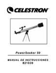
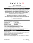
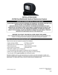
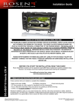
6 Installer setup menu To enter the installer setup menu you must have the system on & opened. Using the remote or CPM, press these buttons in this sequence Eject-Enter-1,1,2,0. If this is done correctly the picture below should pop up on the OSD (On Screen Display). Installation Guide Z-Series DVD Entertainment System AUDIO SETUP Internal FMT: To use the Internal FMT once the install is complete. Press the Speaker button on the remote or the FMM button on the unit’s control panel. The OSD should read “Speaker Sound on FM __ _._ “ at this time the station adjustments should be made by either using the left & right arrows keys on the remote or by using the left or right arrow keys on the units control panel. External FMM (Optional): To enable the EXT FMM (External FM Modulator) use the FMM On switch located on top of the unit Note: By enabling the EXT FMM this will automatically disable the Internal FMT. NOTICE OF INTENDED INSTALLATION AND USE ROSEN ENTERTAINMENT SYSTEMS VIDEO PRODUCTS ARE NOT INTENDED FOR VIEWING BY THE DRIVER, AND ARE TO BE INSTALLED ONLY TO BE VIEWED BY REAR-SEAT OCCUPANTS. IMPROPER INSTALLATION COULD DISTRACT THE DRIVER OR INTERFERE WITH SAFE OPERATION OF THE VEHICLE, WHICH COULD RESULT IN SERIOUS INJURY OR DEATH, AND COULD ALSO VIOLATE STATE LAW. ROSEN ENTERTAINMENT SYSTEMS DISCLAIMS ANY LIABILITY FOR ANY BODILY INJURY OR PROPERTY DAMAGE THAT MAY RESULT FROM ANY IMPROPER OR UNINTENDED INSTALLATION AND/OR USE. BEFORE YOU START THE INSTALLATION, READ THIS GUIDE! Rosen “all-in-one” systems are the easiest-to-install DVD entertainment systems available today. However, we strongly recommend reading this guide before starting the installation! 7 Initial test, reassembly, and pre-delivery re-test You will need to fully test the system to ensure it is working and connected to the vehicle properly. The following steps will guide you through this process. STEP 1: INITIAL TEST (Do this BEFORE you reassemble any Trim Panels) a. Reconnect the vehicle battery if needed b. Install batteries into the remote control and headphones c. Start the vehicle (ensure that it is safe to do so, i.e. there are no tools or people under the hood) d. Perform the following steps, to ensure proper operation: • Close and reopen the unit several times with the Remote Control and control panel buttons • With the display open insert a DVD (in good condition) and select play • Check the audio on the IR headphones • Select the Speaker Button and adjust the vehicle radio as needed to check the audio • Check the video quality and adjust the display settings, if needed • Eject the disc and reinsert it several times • Turn Off the vehicle and wait for the unit to turn off • Test the dome lights for proper operation with the vehicle doors, if applicable STEP 2: REINSTALL all trim panels removed during the installation using care not to damage any harnesses STEP 3: PRE-DELIVERY AND RE-TEST a. Start the vehicle (ensure that it is safe to do so, i.e. there are no tools or people under the hood) b. Perform the following steps • Open the unit using the Remote Control • With the display open insert a DVD (in good condition) and select play • Re-check IR headphones and FMM Audio • Eject the disc • Remove the protective films and clean the unit as needed c. Place the Owners Information package in the Glove Compartment d. Place the IR headphones and remote control in a convenient location For vehicle specific technical tips, please see www.rosendealercentral.com 1 Make sure you have the tools and components you’ll need These common hand tools are needed in almost every installation: Phillips #2 screwdriver Knife and blades Digital multimeter (DMM) 1/4” drive sockets are often needed for dashboard and trim disassembly. Check if Torx or Allen-drive bolts are used on any panels you will be removing. You will need a DVD in good condition when testing the system. Wire cutters, strippers, and a crimping tool Panel-removing tools Marking pen or chalk, masking tape and cleaning cloths Standard installation parts you will need include wire, wire ties, wire crimp connectors or solder, and electrical insulating tape. Installation of aftermarket automotive electronics also often requires access to special parts. It is a good idea to have a source for these common installation parts. 2 Check out the vehicle and plan your work ! IMPORTANT! The vehicle’s roof beam (above the headliner) must support the weight of the overhead console. The supplied mounting bracket must be firmly attached to the roof beam. Determine if this is possible and that the vehicle is suitable for the installation. CHECK THE BATTERY Test the battery voltage to make sure it’s fully charged and inspect battery terminals for tightness and any corrosion. This takes 30 seconds and can save hours of troubleshooting later. DECIDE ON A LOCATION FOR THE MAIN UNIT Location of the main unit varies by vehicle, but is typically on the center line of the vehicle and is always behind of the front seats. Often, the main unit’s dome lights replace the factory dome light. Securely attach the mounting bracket to the existing roof beam(s). Z Series Installation Manual Revision A RES PN AP1025 Copyright 2007 Rosen Entertainment Systems 866-Go Rosen www.rosenentertainment.com Rosen Z-Series Installation Guide 4 Rosen Z-Series Installation Guide 1 3 4 Cutting the headliner and mounting the bracket ! IMPORTANT! Do NOT start this step until you have inspected the headliner, roof beam, and all other essential areas to verify the installation can be successfully completed. It is your responsibility to ensure the installation is safe, secure and appropriate for the vehicle. CAUTION! STOP You will need to cut the headliner to create a path for the cables and mounting bracket. The following steps will guide you through this process STEP 1: LOCATE THE MOUNTING POSITION Using masking tape or chalk, mark the side-to-side centerline of the headliner. Next, mark forward-to-aft position, which locates the display as far forward as possible, but rearward of the front seats. Cutouts for connectors STEP 2: CHECK THE CONTOURS Using the Cutout template located in the mounting position from Step 1, check the headliner for contours. Contours in the headliner will require modifications to an optional trim ring. For extreme contours, you may need to use an optional tall trim ring. Modifing the trim ring to follow the contours is required to avoid problems ranging from no disc eject to poor latch retention. STEP 3: CUT THE HEADLINER Once you are satisfied with the location, using the Cutout template, cut the openings for the cables and four mounting screws. You may also need to cut an opening to slide the mounting bracket through the headliner. ! Cutouts for mounting screws IMPORTANT! Do NOT cut away too much of the headliner. This creates a direct heat path, which can lead to overheating the system during very hot days. CAUTION! STOP Routing the harnesses and making the wiring connections It is the installer’s responsibility to ensure that the safety equipment in the vehicle is NOT adversely affected by installation of this system. Ensure that the routing of the harnesses does NOT obstruct side-curtain airbags, SRS or other safety devices. You will need to route the harnesses above the headliner from the system to your selected connection points. The following steps will guide you through this process. STEP 1: LOCATE POWER CONNECTION POINTS This system requires a minimum of 12V (+) ACC Switched and Ground to operate. The 12V (+) ACC Switched circuit must be capable of supplying 3 Amps minimum. Use a Vehicle Chassis Ground point whenever possible. If the Map Light function is to be enabled, it requires 12V (+) Constant connection point. STEP 2: ROUTE THE HARNESSES Starting at the headliner cutout, route the harnesses to the predetermined locations. Be sure to leave about six inches of cable hanging through the cutout to allow for working room. . STEP 3: PROTECT THE HARNESSES To prevent harness failures, be sure to avoid sharp edges in the vehicle which could cut or damage the harnesses. When ever possible, tape the harnesses in place to avoid vibration noises and long-term wear, which could result in failure. STEP 4: CONNECTING THE POWER HARNESS When connecting the Power Harness, Rosen recommends that all connections are soldered to prevent future failures. However, if T-Taps are being used, be sure to select the proper gage T-Tap for the connection. Failure to do so, will result in intermittent connections and potential product failures in the future. IMPORTANT! NEVER connect the ACC (Red) Power Harness wire to a constant 12V (+) power point, this will cause the systems to remain powered on, after the car is turned off – resulting in premature battery drain. ! Make sure that the screws you use to mount the bracket and/or the main unit are NOT too long! If the screws you select are too long, you will damage the roof of the vehicle. Take great care when planning this part of your installation. 5 Connecting to the domelight wiring in the vehicle ! IMPORTANT! Many vehicles have dome light delay timers which keep the lights on after doors are closed, or shut off the dome light after it has been on for too long. Make sure these timers don’t defeat your testing - occasionally turn the ignition key on and off, and open and close all the doors. Remove the existing vehicle dome light and make the wire connections at the vehicle harness where the dome light was removed as shown below. STEP 1: CONNECTING THE DOME LIGHT FUNCTION Connect the two dome light wires to where the “ends of the lamp” were previously connected, polarity of the wires do not matter. STEP 2: CONNECTING THE MAP LIGHT FUNCTION If a map light feature is desired, connect the yellow wire in the main harness to a TIMED 12V (+) source. If no timed 12V (+) is available, then connection to a constant 12V (+) may be made. However please note that there is no time-out circuit in the Z-Series system itself, thus if the map light is left on, it will drain the battery. Rosen Z-Series Installation Guide 2 Rosen Z-Series Installation Guide 3 Frequently Asked Questions Resetting the System If the system locks up for any reason, reset the unit. Solution: To RESET the system, press and hold the RESET Button for 3 or more seconds. The RESET Button is located in the Display Pocket. Power Harness AP1009 Finding the best power point Avoid connection to wires which supply the following: fan/seat/mirror motors power, excessively large sized wires, glow plug power lines, radio power lines, defroster power lines, etc. Solution: Open power points can be located in the fuse box, which are designed for accessory equipment – when in doubt, check Dealer Central for Tech Tips at www.rosenentertainment.com. The DVD restarts when the vehicle is started Normally the DVD should restart at the point it was when the vehicle was turned off. However, if the voltage falls below approximately 10VDC when starting the vehicle, the system will restart at the beginning of the DVD. Solution: Check the battery to be sure it is fully charged, new vehicles rarely have a fully charged battery. Solution: Older batteries can not provide the necessary voltage during a engine cranking, replace the battery. Solution: Extreme climate conditions (cold or hot) will reduce the efficiency of the battery, be sure the battery is fully charged and in good condition. Replace the battery if needed. Solution: Relocate the 12VDC (+) power point to a more stable location The System shuts down or locks up after a few minutes of operation The System is designed to turn off at low voltages. If the voltage falls below approximately 10VDC the system may shut down to preserve the battery. Solution: Check the battery to be sure it is fully charged, new vehicles rarely have a fully charged battery. Solution: Move the 12V ACC to a new location, the current location may be a timed circuit. Solution: Move the 12V ACC to a new location, the current location may not provide enough current (3 AMPS min). The System stays on and never shuts off The System is designed to shut down when the key is turned off. If the ACC (Red) wire is connected to a constant 12VDC (+) power point the system will system will stay on until the battery dies. Solution: Check the ACC connection point to be sure it is switched with the key, and relocate as needed. Reducing Vibration Noise Loose harnesses and mounting brackets can cause vibration noises in the vehicle. Solution: Place Duct Tape between the Mounting Bracket and the vehicle attachment point to dampen any noises Solution: Tape all wiring harnesses in place to the headliner and vehicle before re-installing the vehicle trim. Discs that Will Not Eject Discs that will not eject are typically the result of too much pressure on the DVD Guide or an improper format disk type. Solution: Try loosening the mounting screws and/or matching the trim ring to the headliner contours. Solution: To EJECT an improper format disc, RESET the system, and then press EJECT repeatedly as the system restarts, the disc will eject. Service and Optional Parts List Part Number Description Part Number Description AP1043 AP1040 AP1009 AC3614 AC3323 AC3196 Remote Control AP1038 AUX In/Out Harness FMM Harness AP1039 Dome Light Harness Power Harness IR Single Channel Headphones Wireless FM Transmiter - Available Frequencies: 87.7, 87.9, 88.1, 88.3, 88.5, 88.7, 88.9 7 Channel FM Modulator - Available Frequencies: 87.7, 87.9, 88.1, 88.3, 88.5, 88.7, 88.9 Specifications Supply Voltage Current Consumption Video Signal Audio Signal IR Audio Signal Discs Played Operating temp : 12VDC negative ground system, 11-16VDC operating range : Less than 3A operational Approximately 0mA, ACC Off : Compositive video 1.0Vp-p 75 , NTSC/PAL : Audio Output : 2Vrms, line output : Channel A= 2.3 MHZ / 2.8 MHZ : (1) 5” (12cm) DVD-VIDEO Disc (2) Compact Disc (CD-DA/CD-R/CD-RW/MP3) : 0 C to +60 C No Headphone Audio The Headphone audio should be preset at all times, unless the MUTE is set to on, or a DVD Setting has been changed in the DVD Settings Menu. Solution: Press the MUTE Button to enable the audio and turn the MUTE OFF. Solution: Confirm that the Headphones have fresh batteries, are turned on, and the ON LED Indicator is Illuminated. Solution: Check the DVD Setting and restore them to FACTORY SETTINGS if needed (see the Owners Manual). Reducing Audio or Video Noise Audio or video noise may be induced into the system from sources ranging from harness location, power point to poor grounding. Solution: Reroute the wire harnesses to avoid passing over other harnesses or near electrical motors. Solution: Check the Power Point by selecting a different 12VDC (+) power point or running a wire directly to the battery. Solution: Check the ground point selected, by moving the ground point to a new location. Solution: In some cases, inline audio filters may be required. Contact Rosen for support on selection of a filter. Checking Firmware Versions Periodically the Firmware may be updated to improve performance. Solution: Verify Firmware load as follows Mpeg: Press EJECT-ENTER-1-2-3-4-5 System: Press EJECT-ENTER-1-1-2-0 Note: Specifications and designs are subject to modification, without notice. Rosen Z-Series Installation Guide Rosen Z-Series Installation Guide