1
MOTION CONTROLLER(SV13/22) (REAL MODE) Programming Manual, type A173UHCP,A273UHCPU
MOTION CONTROLLER
(SV22)
(VIRTUAL MODE)
Programming Manual
type A173UHCPU, A273UHCPU
INTORODUCTION
Thank you for purchasing the Mitsubishi Motion Controller.
This instruction manual describes the handing and precautions of this unit. Incorrect handling will lead to
unforeseen events, so we ask that you please read this manual thoroughly and use the unit correctly.
Please make sure that this manual is delivered to the final user of the unit and that it is stored for future
reference.
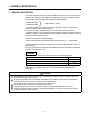
Precautions for Safety
Please read this instruction manual and enclosed documents before starting installation,
operation, maintenance or inspections to ensure correct usage. Thoroughly understand the
machine, safety information and precautions before starting operation.
The safety precautions are ranked as "Warning" and "Caution" in this instruction manual.
WARNING
When a dangerous situation may occur if handling is mistaken
leading to fatal or major injuries.
CAUTION
When a dangerous situation may occur if handling is mistaken
leading to medium or minor injuries, or physical damage.
Note that some items described as cautions may lead to major results depending on the
situation. In any case, important information that must be observed is described.
−I−
For Safe Operations
1. Prevention of electric shocks
WARNING
Never open the front case or terminal covers while the power is ON or the unit is running, as
this may lead to electric shocks.
Never run the unit with the front case or terminal cover removed. The high voltage terminal
and charged sections will be exposed and may lead to electric shocks.
Never open the front case or terminal cover at times other than wiring work or periodic
inspections even if the power is OFF.
The insides of the control unit and servo amplifier are charged and may lead to electric
shocks.
When performing wiring work or inspections, turn the power OFF, wait at least ten minutes,
and then check the voltage with a tester, etc. Failing to do so may lead to electric shocks.
Always ground the control unit, servo amplifier and servomotor with Class 3 grounding.
Do not ground commonly with other devices.
The wiring work and inspections must be done by a qualified technician.
Wire the units after installing the control unit, servo amplifier and servomotor. Failing to do
so may lead to electric shocks or damage.
Never operate the switches with wet hands, as this may lead to electric shocks.
Do not damage, apply excessive stress, place heavy things on or sandwich the cables, as
this may lead to electric shocks.
Do not touch the control unit, servo amplifier or servomotor terminal blocks while the power
is ON, as this may lead to electric shocks.
Do not touch the internal power supply, internal grounding or signal wires of the control unit
and servo amplifier, as this may lead to electric shocks.
2. For fire prevention
CAUTION
Install the control unit, servo amplifier, servomotor and regenerative resistor on inflammable
material. Direct installation on flammable material or near flammable material may lead to
fires.
If a fault occurs in the control unit or servo amplifier, shut the power OFF at the servo
amplifier’s power source. If a large current continues to flow, fires may occur.
When using a regenerative resistor, shut the power OFF with an error signal. The
regenerative resistor may abnormally overheat due to a fault in the regenerative transistor,
etc., and may lead to fires.
Always take heat measures such as flame proofing for the inside of the control panel where
the servo amplifier or regenerative resistor is installed and for the wires used. Failing to do
so may lead to fires.
− II −
3. For injury prevention
CAUTION
Do not apply a voltage other than that specified in user's manual or the instruction manual
for the product you are using on any terminal. Doing so may lead to destruction or damage.
Do not mistake the terminal connections, as this may lead to destruction or damage.
Do not mistake the polarity (+/−), as this may lead to destruction or damage.
The servo amplifier's heat radiating fins, regenerative resistor and servo amplifier, etc., will
be hot while the power is ON and for a short time after the power is turned OFF. Do not
touch these parts as doing so may lead to burns.
Always turn the power OFF before touching the servomotor shaft or coupled machines, as
these parts may lead to injuries.
Do not go near the machine during test operations or during operations such as teaching.
Doing so may lead to injuries.
4. Various precautions
Strictly observe the following precautions.
Mistaken handling of the unit may lead to faults, injuries or electric shocks.
(1) System structure
CAUTION
Always install a leakage breaker on the control unit and servo amplifier power source.
If installation of a magnetic contactor for power shut off during an error, etc., is specified in
the instruction manual for the servo amplifier, etc., always install the magnetic contactor.
Install an external emergency stop circuit so that the operation can be stopped immediately
and the power shut off.
Use the control unit, servo amplifier, servomotor and regenerative resistor with the
combinations listed in user's manual or the instruction manual for the product you are using.
Other combinations may lead to fires or faults.
If safety standards (ex., robot safety rules, etc.,) apply to the system using the control unit,
servo amplifier and servomotor, make sure that the safety standards are satisfied.
If the operation during a control unit or servo amplifier error and the safety direction
operation of the control unit differ, construct a countermeasure circuit externally of the
control unit and servo amplifier.
In systems where coasting of the servomotor will be a problem during emergency stop,
servo OFF or when the power is shut OFF, use dynamic brakes.
Make sure that the system considers the coasting amount even when using dynamic brakes.
In systems where perpendicular shaft dropping may be a problem during emergency stop,
servo OFF or when the power is shut OFF, use both dynamic brakes and magnetic brakes.
The dynamic brakes must be used only during emergency stop and errors where servo OFF
occurs. These brakes must not be used for normal braking.
The brakes (magnetic brakes) assembled into the servomotor are for holding applications,
and must not be used for normal braking.
Construct the system so that there is a mechanical allowance allowing stopping even if the
stroke end limit switch is passed through at the max. speed.
Use wires and cables that have a wire diameter, heat resistance and bending resistance
compatible with the system.
− III −
CAUTION
Use wires and cables within the length of the range described in user's manual or the
instruction manual for the product you are using .
The ratings and characteristics of the system parts (other than control unit, servo amplifier,
servomotor) must be compatible with the control unit, servo amplifier and servomotor.
Install a cover on the shaft so that the rotary parts of the servomotor are not touched during
operation.
There may be some cases where holding by the magnetic brakes is not possible due to the
life or mechanical structure (when the ball screw and servomotor are connected with a
timing belt, etc.). Install a stopping device to ensure safety on the machine side.
(2) Parameter settings and programming
CAUTION
Set the parameter values to those that are compatible with the control unit, servo amplifier,
servomotor and regenerative resistor model and the system application. The protective
functions may not function if the settings are incorrect.
The regenerative resistor model and capacity parameters must be set to values that
conform to the operation mode, servo amplifier and servo power unit. The protective
functions may not function if the settings are incorrect.
Set the mechanical brake output and dynamic brake output validity parameters to values
that are compatible with the system application. The protective functions may not function if
the settings are incorrect.
Set the stroke limit input validity parameter to a value that is compatible with the system
application. The protective functions may not function if the setting is incorrect.
Set the servomotor encoder type (increment, absolute position type, etc.) parameter to a
value that is compatible with the system application. The protective functions may not
function if the setting is incorrect.
Set the servomotor capacity and type (standard, low-inertia, flat, etc.) parameter to values
that are compatible with the system application. The protective functions may not function if
the settings are incorrect.
Set the servo amplifier capacity and type parameters to values that are compatible with the
system application. The protective functions may not function if the settings are incorrect.
Use the program commands for the program with the conditions specified in the instruction
manual.
Set the sequence function program capacity setting, device capacity, latch validity range,
I/O assigment setting, and validity of continuous operation during error detection to values
that are compatible with the system application. The protective functions may not function if
the settings are incorrect.
Some devices used in the program have fixed applications, so use these with the conditions
specified in the instruction manual.
The input devices and data registers assigned to the link will hold the data previous to when
communication is terminated by an error, etc. Thus, an error correspondence interlock
program specified in the instruction manual must be used.
Use the interlock program specified in the special function unit's instruction manual for the
program corresponding to the special function unit.
− IV −
(3) Transportation and installation
CAUTION
Transport the product with the correct method according to the weight.
Use the servomotor suspension bolts only for the transportation of the servomotor. Do not
transport the servomotor with machine installed on it.
Do not stack products past the limit.
When transporting the control unit or servo amplifier, never hold the connected wires or
cables.
When transporting the servomotor, never hold the cabled, shaft or encoder.
When transporting the control unit or servo amplifier, never hold the front case as it may fall
off.
When transporting, installing or removing the control unit or servo amplifier, never hold the
edges.
Install the unit according to user's manual, or the instruction manual for the product you are
using in a place where the weight can be withstood.
Do not get on or place heavy objects on the product.
Always observe the installation direction.
Keep the designated clearance between the control unit or servo amplifier and control panel
inner surface or the control unit and servo amplifier, control unit or servo amplifier and other
devices.
Do not installer operate control units, servo amplifiers or servomotors that are damaged or
that have missing parts.
Do not block the intake/outtake ports of the servomotor with cooling fan.
Do not allow conductive matter such as screw or cutting chips or combustible matter such
as oil enter the control unit, servo amplifier or servomotor.
The control unit, servo amplifier and servomotor are precision machines, so do not drop or
apply strong impacts on them.
Securely fix the control unit and servo amplifier to the machine according to user's manual,
or the instruction manual for the product you are using. If the fixing is insufficient, these may
come off during operation.
Always install the servomotor with reduction gears in the designated direction. Failing to do
so may lead to oil leaks.
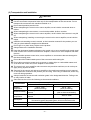
Store and use the unit in the following environmental conditions.
Environment
Ambient
temperature
Ambient humidity
Storage
temperature
Atmosphere
Altitude
Vibration
Conditions
Control unit/Servo Amplifier
Servo Motor
0°C to +55°C
0°C to +40°C
(With no freezing)
(With no freezing)
According to each instruction
80%RH or less
manual
(With no dew condensation)
According to each instruction
−20°C to +65°C
manual
Indoors (where not subject to direct sunlight).
No corrosive gases, flammable gases, oil mist or dust must exist
1000 m (305 Feet) or less above sea level
According to each instruction manual
−V−
CAUTION
When coupling with the synchronization encoder or servomotor shaft end, do not apply
impact such as by hitting with a hammer. Doing so may lead to encoder damage.
Do not apply a load larger than the tolerable load onto the servomotor shaft. Doing so may
lead to shaft breakage.
When not using the unit for a long time, disconnect the power line from the control unit or
servo amplifier.
Place the control unit and servo amplifier in static electricity preventing vinyl bags and store.
When storing for a long time, contact the System Service or Service Station.
(4) Wiring
CAUTION
Correctly and securely wire the wires. Reconfirm the connections for mistakes and the
terminal screws for tightness after wiring. Failing to do so may lead to run away of the
servomotor.
After wiring, install the protective covers such as the terminal covers to the original
positions.
Do not install a phase advancing capacitor, surge absorber or radio noise filter (option FRBIF) on the output side of the servo amplifier.
Correctly connect the output side (terminals U, V, W). Incorrect connections will lead the
servomotor to operate abnormally.
Do not connect a commercial power supply to the servomotor, as this may lead to trouble.
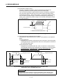
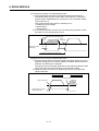
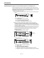
Do not mistake the direction of the surge absorbing diode
Servo amplifier
installed on the DC relay for the control signal output of
VIN
(24VDC)
brake signals, etc. Incorrect installation may lead to signals
not being output when trouble occurs or the protective
functions not functioning.
Control output
RA
Do not connect or disconnect the connection cables
signal
between each unit, the encoder cable or PLC expansion
cable while the power is ON.
Securely tighten the cable connector fixing screws and fixing mechanisms. Insufficient fixing
may lead to the cables combing off during operation.
Do not bundle the power line or cables.
(5) Trial operation and adjustment
CAUTION
Confirm and adjust the program and each parameter before operation. Unpredictable
movements may occur depending on the machine.
Extreme adjustments and changes may lead to unstable operation, so never make them.
If the absolute positioning system is used, zeroing is required after initial start up or after
replacement of a controller or absolute positioning compatible motor.
− VI −
(6) Usage methods
CAUTION
Immediately turn OFF the power if smoke, abnormal sounds or odors are emitted from the
control unit, servo amplifier or servomotor.
Always execute a test operation before starting actual operations after the program or
parameters have been changed or after maintenance and inspection.
The units must be disassembled and repaired by a qualified technician.
Do not make any modifications to the unit.
Keep the effect or magnetic obstacles to a minimum by installing a noise filter or by using
wire shields, etc. Magnetic obstacles may affect the electronic devices used near the control
unit or servo amplifier.
When using the CE mark-compatible equipment, refer to "EMC Installation Guidelines"
(manual number IB(NA)-67339) for the motion controller and to the corresponding EMC
Guideline data for the servo amplifier, inverter and other equipment.
Use the units with the following conditions.
Item
Input power
Input frequency
Tolerable momentary
power failure
Conditions
According to A273UHCPU/A173UHCPU(-S1) user's manual
According to A273UHCPU/A173UHCPU(-S1) user's manual
According to A273UHCPU/A173UHCPU(-S1) user's manual
(7) Remedies for errors
CAUTION
If an error occurs in the self diagnosis of the control unit or servo amplifier, confirm the
check details according to this manual or the instruction manual, and restore the operation.
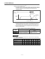
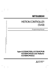
If a dangerous state is predicted in case of a power failure or product failure, use a
servomotor with magnetic brakes or install a brake mechanism externally.
Use a double circuit construction so that the
magnetic brake operation circuit can be
Shut off with the
Shut off with servo ON signal OFF,
emergency stop
operated by emergency stop signals set
alarm, magnetic brake signal.
signal(EMG).
externally.
If an error occurs, remove the cause, secure
Servo motor
RA1
EMG
the safety and then resume operation.
The unit may suddenly resume operation
Magnetic
24VDC
brakes
after a power failure is restored, so do not go
near the machine. (Design the machine so
that personal safety can be ensured even if
the machine restarts suddenly.)
(8) Maintenance, inspection and part replacement
CAUTION
Perform the daily and periodic inspections according to user's manual or the instruction
manual for the product you are using.
Perform maintenance and inspection after backing up the program and parameters for the
control unit and servo amplifier.
− VII −
CAUTION
Do not place fingers or hands in the clearance when opening or closing any opening.
Periodically replace consumable parts such as batteries according to user's manual or the
instruction manual for the product you are using.
Do not touch the lead sections such as ICs or the connector contacts.
Do not place the control unit or servo amplifier on metal that may cause a power leakage or
wood, plastic or vinyl that may cause static electricity buildup.
Do not perform a mugger test (insulation resistance measurement) during inspection.
When replacing the control unit or servo amplifier, always set the new unit settings correctly.
To prevent positional displacements after a controller or absolute positioning compatible
motor is replaced, use one of the following methods to conduct zeroing.
1) PC write the servo data with the peripheral device, turn the power OFF and back ON,
then conduct zeroing.
2) Use the peripheral device back-up functions to load the data backed up before
replacement.
After maintenance and inspections are completed, confirm that the position detection of the
absolute position detector function is correct.
Do not short circuit, charge, overheat, incinerate or disassemble the batteries.
The electrolytic capacitor will generate gas during a fault, so do not place your face near the
control unit or servo amplifier.
The electrolytic capacitor and fan will deteriorate. Periodically change these to prevent
secondary damage from faults. Replacements can be made by the System Service or
Service Station.
(9) Disposal
CAUTION
Dispose of this unit as general industrial waste.
Do not disassemble the control unit, servo amplifier or servomotor parts.
Dispose of the battery according to local laws and regulations.
(10) General cautions
CAUTION
All drawings provided in the instruction manual show the state with the covers and safety
partitions removed to explain detailed sections. When operating the product, always return the
covers and partitions to the designated positions, and operate according to this manual.
− VIII −
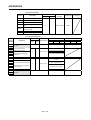
Revisions
*The manual number is given on the bottom left of the back cover.
Print Date
*Manual Number
Revision
Jun.,2001
IB(NA)-0300029-A First edition
This manual confers no industrial property rights or any rights of any other kind, nor does it confer any patent
licenses. Mitsubishi Electric Corporation cannot be held responsible for any problems involving industrial
property rights which may occur as a result of using the contents noted in this manual.
© 2001 Mitsubishi Electric Corporation
CONTENTS
1. GENERAL DESCRIPTION ....................................................................................................... 1- 1 to 1- 6
1.1 System Configuration ........................................................................................................................ 1- 2
1.1.1 A273UHCPU System overall configuration ................................................................................ 1- 2
1.1.2 A173UHCPU(-S1) System overall configuration ........................................................................ 1- 4
1.2 Summary of REAL and VIRTUAL Modes ......................................................................................... 1- 5
2. PROCEDURE FOR VIRTUAL MODE POSITIONING CONTROL........................................... 2- 1 to 2- 8
2.1 System Start-Up ...............................................................................................................................
2.2 Operation..........................................................................................................................................
2.2.1 Operation with incremental system ...........................................................................................
2.2.2 Operation with an absolute (absolute position) system .............................................................
2.3 Differences Between the REAL and VIRTUAL Modes.....................................................................
2.3.1 Positioning data .........................................................................................................................
2.3.2 Positioning device......................................................................................................................
2.3.3 Servo program...........................................................................................................................
2.3.4 Control change (current value change & speed change) ..........................................................
2- 1
2- 4
2- 4
2- 5
2- 6
2- 6
2- 6
2- 7
2- 8
3. PERFORMANCE SPECIFICATIONS ....................................................................................... 3- 1 to 3- 2
4. SERVO SYSTEM CPU DEVICES ........................................................................................... 4- 1 to 4-46
4.1 Internal Relays ................................................................................................................................. 4- 1
4.1.1 Internal relay list......................................................................................................................... 4- 1
4.1.2 Axis statuses ............................................................................................................................. 4- 3
4.1.3 Axis command signals............................................................................................................... 4- 4
4.1.4 Virtual servo motor axis statuses .............................................................................................. 4- 5
4.1.5 Virtual servo motor axis command signals................................................................................ 4- 6
4.1.6 Synchronous encoder axis statuses.......................................................................................... 4- 7
4.1.7 Synchronous encoder axis command signals ........................................................................... 4- 7
4.1.8 Common devices....................................................................................................................... 4- 8
4.2 Data Registers ................................................................................................................................ 4-26
4.2.1 Data register list........................................................................................................................ 4-26
4.2.2 Axis monitor devices................................................................................................................. 4-27
4.2.3 Control change registers .......................................................................................................... 4-28
4.2.4 Virtual servo motor axis monitor devices.................................................................................. 4-29
4.2.5 Current values after virtual servo motor axis main shaft's differential gear.............................. 4-30
4.2.6 Synchronous encoder axis monitor devices ............................................................................. 4-31
4.2.7 Current values after synchronous encoder axis main shaft's differential gear ......................... 4-31
4.2.8 Cam axis monitor devices ........................................................................................................ 4-32
4.2.9 Common devices...................................................................................................................... 4-33
4.3 Special Relays/Special Registers List ............................................................................................. 4-40
4.3.1 Special relays ........................................................................................................................... 4-40
4.3.2 Special registers ....................................................................................................................... 4-42
−I−
5. MECHANICAL SYSTEM PROGRAM....................................................................................... 5- 1 to 5- 4
5.1 Mechanical Module Connection Diagram ........................................................................................
(1) Block ........................................................................................................................................
(2) System .....................................................................................................................................
(3) Transmission module connections ..........................................................................................
5.2 Mechanical Module List....................................................................................................................
5- 2
5- 3
5- 3
5- 3
5- 4
6. DRIVE MODULE.......................................................................................................................6- 1 to 6-36
6.1 Virtual Servo Motor........................................................................................................................... 6- 1
6.1.1 Virtual servo motor operation .................................................................................................... 6- 1
(1) START procedure ............................................................................................................. 6- 1
(2) Procedure for stopping before completion ........................................................................ 6- 3
(3) Control items ..................................................................................................................... 6- 3
(4) Control change .................................................................................................................. 6- 3
(5) Operation mode when error occurs................................................................................... 6- 4
(6) Virtual servo motor axis continuous operation .................................................................. 6- 5
(7) Reverse return during positioning ..................................................................................... 6- 5
6.1.2 Parameter list ............................................................................................................................ 6- 8
(1) Virtual axis No. setting....................................................................................................... 6- 8
(2) Stroke limit UPPER/LOWER limit settings ........................................................................ 6- 8
(3) Command in-position range ............................................................................................. 6-10
(4) JOG speed limit and parameter block settings ................................................................ 6-10
6.1.3 Virtual servo motor axis devices (internal relays, data registers) ............................................. 6-11
(1) Virtual servo motor axis status ......................................................................................... 6-11
(2) Virtual servo motor axis command signals....................................................................... 6-16
(3) Virtual servo motor axis monitor device ........................................................................... 6-21
(4) Current value after virtual servo motor axis main shaft differential gear .......................... 6-23
6.2 Synchronous Encoder ..................................................................................................................... 6-25
6.2.1 Synchronous encoder operation............................................................................................... 6-25
(1) Operation START............................................................................................................. 6-25
(2) Operation END ................................................................................................................. 6-26
(3) STOP procedure .............................................................................................................. 6-27
(4) Control items .................................................................................................................... 6-27
(5) Control change ................................................................................................................. 6-27
(6) Operation mode when error occurs.................................................................................. 6-28
6.2.2 Parameter list ........................................................................................................................... 6-29
6.2.3 Synchronous encoder axis device (internal relay, data register) .............................................. 6-30
(1) Synchronous encoder axis device.................................................................................... 6-30
(2) Synchronous encoder axis command signal.................................................................... 6-31
(3) Synchronous encoder axis monitor device....................................................................... 6-32
(4) Current value after synchronous encoder axis main shaft differential gear ..................... 6-33
6.3 Virtual Servo Motor / Synchronous Encoder Control Change ......................................................... 6-34
6.3.1 Virtual servo motor control change........................................................................................... 6-34
(1) Control change registers .................................................................................................. 6-34
(2) Current value change ....................................................................................................... 6-35
− II −
6.3.2 Synchronous encoder control change ...................................................................................... 6-36
(1) Current value change by the CHGA instruction................................................................ 6-36
7. TRANSMISSION MODULE ..................................................................................................... 7- 1 to 7-31
7.1 Gear ................................................................................................................................................. 7- 3
7.1.1 Operation................................................................................................................................... 7- 3
7.1.2 Parameters ................................................................................................................................ 7- 3
(1) Gear ratio .......................................................................................................................... 7- 4
(2) Direction of rotation of output shaft ................................................................................... 7- 4
7.2 Clutch ............................................................................................................................................... 7- 5
7.2.1 Explanation of clutch operation ................................................................................................. 7- 9
(1) ON/OFF mode................................................................................................................... 7- 9
(2) Address mode .................................................................................................................. 7-10
(3) Address mode 2 ............................................................................................................... 7-13
(4) One-shot mode................................................................................................................. 7-15
(5) External input mode ......................................................................................................... 7-20
7.2.2 Parameters ............................................................................................................................... 7-24
(1) Control mode.................................................................................................................... 7-24
(2) Mode setting device.......................................................................................................... 7-25
(3) Clutch ON/OFF command device .................................................................................... 7-25
(4) Clutch ON/OFF address setting device............................................................................ 7-26
(5) Smoothing method ........................................................................................................... 7-26
(6) Smoothing time constant.................................................................................................. 7-26
(7) Amount of slip setting device (2 words) ........................................................................... 7-26
7.3 Speed Change Gear ....................................................................................................................... 7-27
7.3.1 Operation.................................................................................................................................. 7-27
7.3.2 Parameter list ........................................................................................................................... 7-28
(1) Speed change gear ratio upper limit value/lower limit value ............................................ 7-28
(2) Speed change gear ratio setting device ........................................................................... 7-29
(3) Smoothing time constant.................................................................................................. 7-29
7.4 Differential Gear .............................................................................................................................. 7-30
7.4.1 Operation.................................................................................................................................. 7-30
(1) When the input shaft clutch is engaged ........................................................................... 7-30
(2) When the input shaft clutch is disengaged....................................................................... 7-30
(3) When the differential gear is used to connect to the virtual main shaft............................ 7-31
7.4.2 Parameters (setting not necessary) ......................................................................................... 7-31
8. OUTPUT MODULES ............................................................................................................... 8- 1 to 8-63
8.1 Rollers ..............................................................................................................................................
8.1.1 Roller operation .........................................................................................................................
(1) Operation...........................................................................................................................
(2) Control details....................................................................................................................
− III −
8- 4
8- 4
8- 4
8- 4
8.1.2 Parameter list ............................................................................................................................ 8- 5
(1) Unit setting......................................................................................................................... 8- 5
(2) Roller diameter (L) / Number of PULSES per roller revolution(NL) ................................... 8- 5
(3) Permissible droop pulse value .......................................................................................... 8- 6
(4) Speed control limit (VL) ..................................................................................................... 8- 6
(5) Torque limit value setting device (1 word)......................................................................... 8- 6
(6) Comment........................................................................................................................... 8- 6
8.2 Ball Screws....................................................................................................................................... 8- 7
8.2.1 Ball screw operation .................................................................................................................. 8- 7
(1) Operation........................................................................................................................... 8- 7
(2) Control details.................................................................................................................... 8- 7
8.2.2 Parameter list ............................................................................................................................ 8- 8
(1) Unit setting......................................................................................................................... 8- 8
(2) Ball screw pitch (P) / Number of PULSES per ball screw revolution (NP)......................... 8- 8
(3) Permissible droop pulse value .......................................................................................... 8- 9
(4) Stroke limit upper limit value/lower limit value................................................................... 8- 9
(5) Speed limit value (VL)........................................................................................................ 8- 9
(6) Limit switch output............................................................................................................. 8- 9
(7) Torque limit value setting device (1 word)........................................................................ 8-10
(8) Comment.......................................................................................................................... 8-10
8.3 Rotary Tables .................................................................................................................................. 8-11
8.3.1 Rotary table operation .............................................................................................................. 8-11
(1) Operation.......................................................................................................................... 8-11
(2) Control details................................................................................................................... 8-11
8.3.2 Parameter list ........................................................................................................................... 8-12
(1) Number of PULSES per rotary table revolution (ND)........................................................ 8-12
(2) Permissible droop pulse value ......................................................................................... 8-12
(3) Stroke limit upper limit value/lower limit value.................................................................. 8-12
(4) Speed limit value (VL) ....................................................................................................... 8-13
(5) Limit switch output............................................................................................................ 8-13
(6) Torque limit value setting device (1 word)........................................................................ 8-13
(7) Comment.......................................................................................................................... 8-13
(8) Virtual axis present value in one revolution storage device
(main shaft side)(2 words) ................................................................................................ 8-14
(9) Virtual axis present value in one revolution storage device
(auxiliary input shaft side)(2 words) .................................................................................. 8-16
8.4 Cams............................................................................................................................................... 8-18
8.4.1 Cam operation .......................................................................................................................... 8-19
(1) Procedure for switching from the REAL mode to the VIRTUAL mode............................. 8-19
(2) Processing on switching from the REAL mode to the VIRTUAL mode............................ 8-19
(3) Operation.......................................................................................................................... 8-19
(4) Switching the stroke and cam No. during operation......................................................... 8-20
(5) Control details................................................................................................................... 8-21
(6) Changing control .............................................................................................................. 8-22
(7) Example sequence program ............................................................................................ 8-22
− IV −
8.4.2 Settings when creating cam data .............................................................................................
(1) Cam No. ...........................................................................................................................
(2) Resolution.........................................................................................................................
(3) Stroke/cam No. change point ...........................................................................................
(4) Control mode....................................................................................................................
(5) Cam data table .................................................................................................................
8.4.3 Parameter list ...........................................................................................................................
(1) Number of PULSES per cam shaft revolution (NC)..........................................................
(2) Used cam No....................................................................................................................
(3) Cam No. setting device (1 word) ......................................................................................
(4) Permissible droop pulse value .........................................................................................
(5) Unit setting........................................................................................................................
(6) Stroke setting device (2 words) ........................................................................................
(7) Limit switch output............................................................................................................
(8) Torque limit setting device (1 word) .................................................................................
(9) Comment..........................................................................................................................
(10) Stroke lower limit value storage device ..........................................................................
(11) Virtual axis current value in one revolution storage device
(main shaft side)(2 words)..............................................................................................
(12) Virtual axis current value in one revolution storage device
(auxiliary input shaft side)(2 words)................................................................................
8.4.4 Cam curve list...........................................................................................................................
(1) Cam curve characteristics ................................................................................................
(2) Free-form curve................................................................................................................
8.4.5 Creation of cam data by user ...................................................................................................
8.4.6 Limit switch outputs in current value mode & real current value in 1 cam revolution mode .....
(1) Limit switch outputs in real current value mode ...............................................................
(2) Limit switch outputs in 1 cam shaft revolution current value ............................................
8.4.7 Limit switch output data in current value within 1 cam revolution mode...................................
8.4.8 Batch-changing the cam data/limit switch output data .............................................................
8.5 Common Devices (Input/Output, Internal Relays, Data Registers) ................................................
8.5.1 Internal relays (M).....................................................................................................................
(1) Internal relay (M) list .........................................................................................................
(2) Internal relay (M) details ...................................................................................................
8.5.2 Data registers (D) .....................................................................................................................
(1) Data register (D) list .........................................................................................................
(2) Data register (D) details ...................................................................................................
8-23
8-23
8-23
8-23
8-24
8-25
8-26
8-26
8-26
8-27
8-27
8-27
8-27
8-28
8-28
8-29
8-29
8-29
8-32
8-34
8-34
8-34
8-34
8-41
8-41
8-42
8-44
8-46
8-51
8-51
8-51
8-53
8-60
8-60
8-62
9. REAL & VIRTUAL MODE SWITCHING AND STOP/RESTART ............................................ 9- 1 to 9-10
9.1 Switching from the REAL to VIRTUAL Mode ...................................................................................
9.2 Switching from the VIRTUAL to REAL Mode ...................................................................................
9.2.1 VIRTUAL to REAL mode switching by user ..............................................................................
9.2.2 VIRTUAL to REAL mode switching by OS ................................................................................
9.3 Precautions When Switching between REAL and VIRTUAL Modes ...............................................
9.4 STOP & RESTART ..........................................................................................................................
−V−
9- 1
9- 5
9- 5
9- 5
9- 6
9- 8
10. AUXILIARY / APPLIED FUNCTIONS..................................................................................10- 1 to 10- 4
10.1 Current Value Change / Speed Change........................................................................................ 10- 1
10.1.1 Current value change by CHGA instruction and speed change by CHGV instruction ............ 10- 1
10.2 Improved Current Value Management .......................................................................................... 10- 3
11. ERROR CODES STORED AT THE PCPU ........................................................................11- 1 to 11-32
11.1
11.2
11.3
11.4
11.5
11.6
Related Systems & Error Processing............................................................................................ 11- 4
Servo Program Setting Errors ....................................................................................................... 11- 5
Drive Module Errors ...................................................................................................................... 11- 8
Servo Errors ................................................................................................................................. 11-11
Output Module Errors ................................................................................................................... 11-25
Error At REAL ↔ VIRTUAL Mode Switching ............................................................................... 11-31
APPENDICES ..................................................................................................................... APP- 1 to APP-28
APPENDIX 1 Cam Curves ................................................................................................................... APP- 1
APPENDIX 2 Processing Time List...................................................................................................... APP- 5
APPENDIX 3 Setting Range of Indirect Setting Devices..................................................................... APP-23
Appendix 3.1 Servo program ............................................................................................................ APP-23
Appendix 3.2 Mechanical system program ....................................................................................... APP-25
APPENDIX 4 Magnitude Comparison and Four Fundamental Operations of 32-Bit Monitor Data..... APP-27
− VI −
1. GENERAL DESCRIPTION
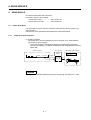
1. GENERAL DESCRIPTION
The A273UHCPU/A173UHCPU(-SI) (hereafter referred to as "servo system CPU")
features two operating modes (REAL and VIRTUAL) at motion controllers where
the operating systems (OS) shown below have been installed:
• SW2SRX-SV22U
• SW2SRX-SV22A
.......... Abbreviated to “SV22”
This manual explains the mechanical system program required to operate the
motion controller in the VIRTUAL mode.
In order to execute positioning control in the VIRTUAL mode, positioning
parameter settings, servo programs, and a positioning sequence program must be
created in addition to the mechanical system program. Details for these procedures
are given in the following manual:
Motion Controller (SV13/22 REAL Mode)
Programming Manual (type A273UHCPU/A173UHCPU(-S1))....... IB-0300028
Differences between the REAL and VIRTUAL modes are discussed in section 2.3
of this manual.
Be sure to familiarize yourself with these differences before attempting positioning
control in the VIRTUAL mode.
REMARK
(1) Abbreviations used in this manual are shown in the following table.
Names
IBM PC/AT in which PC-DOS V5.0 or later version is installed
MR-H-BN/MR-J2S-B/MR-J2-B type servo amplifier
AC motor drive module
Abbreviation
IBM PC
MR- -B
ADU
IBM PC/AT is a register trade mark of the International Business Machines
Corporation.
CAUTION
When designing the system, provide external protective and safety circuits for safety in the event
of trouble with the motion controller.
Printed circuit boards have components susceptible to the effects of static electricity mounted on
them: ground your body or the work bench before handling them.
Do not directly touch conductive or electric parts of the product.
Set parameter within the ranges indicated in this manual.
Use the program instructions in accordance with the conditions stipulated in this manual.
Some of the devices used in programs have fixed applications: use them in accordance with the
conditions stipulated in this manual.
1−1
1. GENERAL DESCRIPTION
1.1
System Configuration
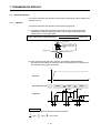
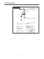
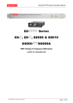
1.1.1
A273UHCPU System overall configuration
The following system configuration assumes use of the A273UHCPU.
A62P
Battery module
A270BATCBL
MR-J-BAT
Brake output
Servo power
supply module
Dynamic brake
module
Servo external
signal
CPU base unit
(A278B/A275B)
CPU module
Control power
supply module
Motion slots
AC motor drive
modules
A273UH A278 A240 A221 A211 A222AM-20 A230P
CPU
LX
DY
AM-20 AM-20
Regenerative brake resistor
Three-phase power supply
200V
BRAKE
A6BAT
Emergency
stop input
DBOUT DB IN+
DBCOM DB IN-
AC100/200V
Teaching unit
A31TU/A30TU(SV13 only)
Max. 16 ADU axes
M
E
M
E
PLC slots
M
E
PLC extension base connection cable(A370C
RS422
External input signals
FLS
Upper limit switch
RLS
Lower limit switch
STOP
Stop signal
DOG
Proximity dog
CHANGE Speed-position change
Personal computer(IBM PC/AT)
Windows NT /
Windows 98
SSCNET4
SSCNET1
SSCNET2
d1
d2
M
E
A62P A273
EX
d3
d8
M
E
M
E
M
E
Servo amplifier, max. 8 axes/1 network
AI61
Input module
Interrupt input module
Control power supply
module
Pulse generator/
synchronous
encoder interface module
Motion extension base unit
(A255B/A268B)
PLC extension base(A68B/A65B/A62B)
PLC extension bases: up to 7 bases
Base number setting: base 1 to base 7
Termination
resistor
SSCNET3
Motion extension base
connection cable
(AC
B)
B)
8
AX
AY
I/O composite module
SSC I/F card/board
(A30CD-PCF/A30BD-PCF)
(AC
B)
MR-H-BN/MR-J2S-B/MR-J2-B
(Max. 32 axes including those of ADU)
Max. 24 axes
Output module
Communication cable
(A270CDCBL M/
A270BDCBL M)
Manual pulse
generator 3
(MR-HDP01)
Serial absolute
synchronous encoder 3
(MR-HENC)(SV22 only)
M
E
Power supply module
M
E
AH42
A42XY
P
Serial absolute
synchronous encoder
cable (MR-HSCBL M)
External interrupt input signals
16 points (I0 to I15)
E
External input signal
TRA Tracking 3
SSCNET : Servo System Controller NETwork
Motion extension base, up to 4 bases
(Base number setting: base 1 to base 4)
1−2
1. GENERAL DESCRIPTION
NOTES
(1) A servo system CPU can be connected to a maximum of four motion
extension base unit.
(2) The motion extension base units which can be used are indicated below.
• A255B (control power supply not required)
• A268B (control power supply required)
(3) When using a teaching unit A31TU-E with dead-man switch, a dedicated
connecting cable A31TUCBL03M is required between the CPU module
and A31TU-E connector. If the A31TU-E is connected directly to the
RS422 connector of the CPU without using a dedicated cable, the A31TUE will not operate at all.
After disconnecting the A31TU-E, attach a short-circuit connector
A31TUSHORTCON for A31TUCBL.
(4) When the power supply to the servo system CPU is switched ON and
OFF, erroneous process outputs may temporarily be made due to the
delay between the servo system CPU power supply and the external
power supply for processing (especially DC), and the difference in startup
times. For example, if the power supply to the servo system CPU comes
on after the external power supply for processing comes on at a DC output
module, the DC output module may temporarily give erroneous outputs
when the power to the servo system CPU comes on. Accordingly a circuit
that ensures that the power supply to the servo system CPU comes on
first should be constructed.
1−3
1. GENERAL DESCRIPTION
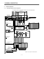
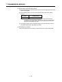
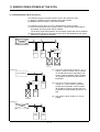
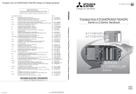
1.1.2
A173UHCPU(-S1) System overall configuration
Extension cable
A1SC B: For A1S6 B, A168B
A1S NB: For A6 B
A173UHCPU A172S A172S A172S A172S A1S
ENC
ENC ENC ENC
I61
Emergency
stop input
AC100/200V
Teaching unit
A31TU-E/A30TU-E
(SV13 only)
GOT
Power supply
module
Battery
A6BAT
Pulse generator/
synchronous encoder
interface module
Interrupt input module
CPU base unit
A178B-S3
/A178B-S2
/A178B-S1
/A17 B
CPU module
Motion slots
External interrupt input signals
16 points (I0 to I15)
P
Manual pulse generator
(MR-HDP01)
P
3
PLC extension base
For A1S6 B: up to 1 base
For A168B (GOT compatible) : up to 1 base
For A6 B : up to 1 base
P
Serial absolute
synchronous encoder cable
(MR-HSCBL M)
Serial absolute
synchronous encoder 4
(MR-HENC)
E
RS422
E
E
Communication cable
(A270CDCBL M/
A270BDCBL M)
Personal computer
(IBM PC/AT)
Windows NT /
(Note)
Windows 98
SSCNET4
E
External input signals
FLS
RLS
STOP
DOG/CHANGE
TRA
SSC I/F card/board
(A30CD-PCF/A30BD-PCF)
Upper limit switch
Lower limit switch
Stop signal
Proximity dog/speed-position change
Tracking
8
1
Brake output
Motion network cable
(Note)
Max. 24 axes
SSCNET1
SSCNET2
SSCNET3
SSCNET4
d1
d2
MR-H-BN/MR-J2S-B/MR-J2-B
Servo amplifier, max. 32 axes
d3
d8
Termination
resistor
M
E
M
E
M
E
M
E
Servo amplifier, max. 8 axes/1 network
(Note): The A173UHCPU may be used with 4 channels
of SSCNET.
When using the SSC I/F card/board
(A30CD-PCF/A30BD-PCF), connect it to
SSCNET4 and connect the servo amplifiers to
SSCNET1 to 3.
In this case, up to 24 axes of servo amplifiers
can be connected.
NOTES
(1) Use the A168B when using the bus-connection type GOT.
(2) When using a teaching unit A31TU-E with dead-man switch, a dedicated
connecting cable A31TUCBL03M is required between the CPU module
and A31TU-E connector. If the A31TU-E is connected directly to the
RS422 connector of the CPU without using a dedicated cable, the A31TUE will not operate at all.
After disconnecting the A31TU-E, attach a short-circuit connector
A31TUSHORTCON for A31TUCBL.
(3) The motion slots also accept PLC A1S I/O modules.
(4) The motion slots accept one A1SI61 interrupt input module.
This module is designed for only event/NMI input to the motion CPU and is
irrelevant to PLC interrupt programs.
(5) The motion slots accept up to 256 I/O points.
(6) The I/O numbers of the I/O modules loaded in the motion slots should be
later than the I/O numbers used with the PLC slots.
1−4
1. GENERAL DESCRIPTION
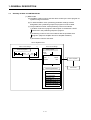
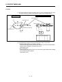
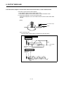
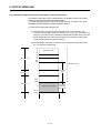
1.2
Summary of REAL and VIRTUAL Modes
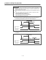
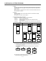
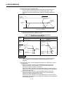
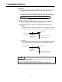
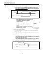
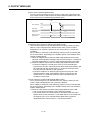
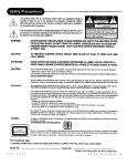
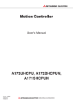
(1) REAL mode
(a) The REAL mode is used to execute direct control by the servo program at
systems using servomotors.
(b) To utilize the REAL mode, positioning parameter settings must be
designated ,and a positioning sequence program must be created.
(c) The procedure for REAL mode positioning control is as follows:
1) A REAL mode servo program "start request" is issued with a SVST
instruction in the positioning sequence program.
2) Positioning control occurs in accordance with the specified servo
program. (Output to amplifier and servo amplifier modules.)
3) Servomotor control is executed.
Servo System CPU
SCPU Control Range
1)
Servo program
Sequence program
SVST
PCPU Control Range
J1
K15
REAL
<K15>
ABS-1
Axis
1,
100000
Speed
2)
3)
Positioning parameters
System setting
Fixed parameters
Servo parameters
Parameter block
Zeroing data
JOG operation data
Limit switch output data
1−5
Servo amplifier
1000
Servomotor
1. GENERAL DESCRIPTION
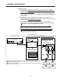
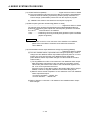
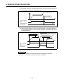
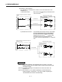
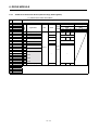
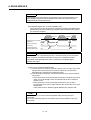
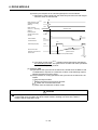
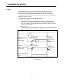
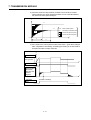
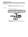
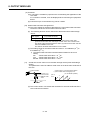
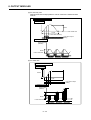
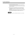
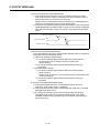
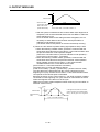
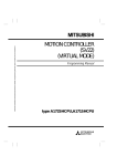
(2) VIRTUAL mode
(a) The VIRTUAL mode is used to execute synchronous processing (with
software) using a mechanical system program comprised of a virtual main
shaft and mechanical module.
This mode permits the synchronous control for conventional positioning by
main shaft, gear, and cam, etc., to be replaced by a servomotor positioning
control format.
(b) In addition to the positioning parameter settings, servo program, and
positioning sequence program used in the REAL mode, the VIRTUAL mode
also requires a mechanical system program.
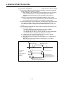
(c) The procedure for VIRTUAL mode positioning control is as follows.
1) A VIRTUAL mode servo program "start request" is issued with a SVST
instruction in the positioning sequence program.
2) The mechanical system program's virtual servomotor is started.
3) The calculation result from the transmission module is output to the
amplifier module/servo amplifier designated for the output module.
4) Servomotor control is executed.
Servo System CPU
SCPU Control Range
PCPU Control Range
1)
Sequence program
SVST
Servo program
J1
K2000
Mechanical system program
VIRTUAL
< K2000>
Drive module
(virtual servomotor)
Transmission module
ABS-1
Axis
1,
Speed
100000
1000
2)
(Axis 1)
Positioning parameters
System setting
Fixed parameters
Servo parameters
Parameter block
Limit switch output data
Output
module
3)
Zeroing data is not used in the VIRTUAL mode because a zeroing operation is impossible.
(Zeroing occur in the REAL mode.)
VIRTUAL mode JOG operations occur in accordance with the JOG operation data designated
at the drive module parameters.
4)
1−6
Servo amplifier
Servo amplifier
Servomotor
Servomotor
2. PROCEDURE FOR VIRTUAL MODE POSITIONING CONTROL
2. PROCEDURE FOR VIRTUAL MODE POSITIONING CONTROL
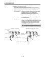
The procedure for VIRTUAL mode positioning control is discussed in this section.
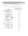
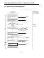
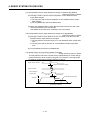
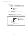
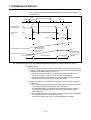
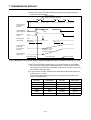
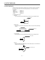
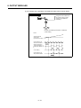
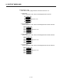
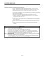
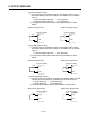
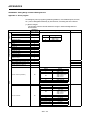
2.1
System Start-Up
The procedure for a VIRTUAL mode system start-up is shown below.
Reference Section
Reference Manual
SW2SRX-GSV22PE,
Motion Controller
(SV13/22 REAL Mode) SW0IX-CAMPE
Operating Manual
Programming Manual
(type A273UH/A173UH)
START
Chapter 4
Register SW2SRX-GSV22PE,
SW0SRX-CAMPE
Section 6.1
Start SW2SRX-GSV22PE
Designate system settings
Designate the following
positioning parameter settings:
• Fixed parameters
• Servo parameters
• Parameter block
Section 2.3
Conduct a relative check and
correct setting errors
Will cam be used?
Setting by
peripheral
device
Chapter 4
Chapter 7
Chapter 4
Chapter 8
Section 8.4
NO
YES
Write setting data to hard disk
or floppy disk, then end
SW2SRX-GSV22PE operation
Section 6.2
Section 21.1
Start SW0IX-CAMPE
(1)
(11)
2−1
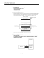
2. PROCEDURE FOR VIRTUAL MODE POSITIONING CONTROL
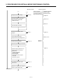
Reference Section
(1)
Designate cam data settings
(11)
Section 8.4
Reference Manual
Motion Controller
(SV13/22 REAL Mode)
Programming Manual
(type A273UH/A173UH)
SW2SRX-GSV22PE,
SW0IX-CAMPE
Operating Manual
Chapter 22
Write setting data to hard disk or
floppy disk, then end SW0IX
- CAMPE operation
Section 21.2
Section 6.1
Start SW2SRX-GSV22PE
Create the mechanical system
program
Chapter 10
Section 5
Check mechanical system
program and correct setting errors
Create the servo program
Section 10.2.5
Section 2.3
Section 6
Section 7
Switch the power supply module ON
Chapter 11
Write the following data from the
peripheral device to the servo
system CPU:
• System setting data
• Positioning data
• Servo program
• Mechanical system program
• Cam data
• Sequence program
Turn the "PLC READY" signal
(M2000) ON
Section 4.1
Execute an "all-axes servo START
request" (switch M2042 ON)
Section 4.1
(2)
2−2
2. PROCEDURE FOR VIRTUAL MODE POSITIONING CONTROL
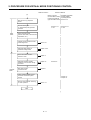
Reference Section
(2)
Motion Controller
(SV13/22 REAL Mode)
Programming Manual
(type A273UH/A173UH)
Start-up servo by peripheral
device
Execute zeroing test
by JOG/manual pulse generator
operation
REAL
Mode
VIRTUAL
Mode
Reference Manual
Sections 7.19
to 7.21
SW2SRX-GSV22PE/
SW0IX-CAMPE
Operating Manual
Section 12.2
Sections 12.4
to 12.6
Adjust cam setting axis
(bottom dead center, stroke amount
adjustments, etc.)
VIRTUAL mode operation START
position alignment
Section 8.5
Designate data settings at
parameter setting device
Chapter 6 to 8
Switch from REAL mode to
VIRTUAL mode
Chapter 9
Designate operation START
address by current value change
procedure
Chapter 10
Start drive module
operation/motion
Chapter 6
Check operation status at servo
monitor & mechanical system
monitor
Execute clutch ON/OFF switching
to check operation
Section 8.8
Chapter 13
Chapter 14
Section 7.2
END
2−3
2. PROCEDURE FOR VIRTUAL MODE POSITIONING CONTROL
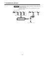
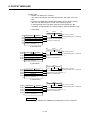
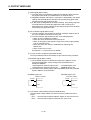
2.2
Operation
The preparation procedure for VIRTUAL mode operation is shown below.
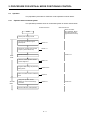
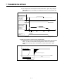
2.2.1
Operation with incremental system
The operation procedure when an incremental system is used is shown below.
Reference Section
Reference Manual
Motion Controller
(SV13/22 REAL Mode)
Programming Manual
(type A273UH/A173UH)
START
Switch power supply unit ON
REAL
Mode
Turn the "PLC READY" signal
(M2000) ON
Section 4.1
Execute an "all-axes servo START
request" (switch M2042 ON)
Section 4.1
VIRTUAL mode operation START
position alignment
VIRTUAL
Mode
Section 7.21
Execute a zeroing
Section 8.5
Designate data settings at parameter
setting device
Chapter 6 to 8
Switch from REAL mode to VIRTUAL
mode
Chapter 9
Designate operation START
address by current value change
procedure
Chapter 10
Execute VIRTUAL mode operation
2−4
Section 8.8
2. PROCEDURE FOR VIRTUAL MODE POSITIONING CONTROL
2.2.2
Operation with an absolute (absolute position) system
The operation procedure when an absolute system is used is shown below.
Reference Section
Reference Manual
Motion Controller
(SV13/22 REAL Mode)
Programming Manual
(type A273UH/A173UH)
START
Switch the power supply unit ON
Turn the "PC READY" signal
(M2000) ON
Section 4.1
Execute an "all-axes servo START
request" (switch M2042 ON)
Section 4.1
Is the "home
position return request"
signal ON?
NO
Section 3.1
YES
Section 7.21
Execute a home position return
Section 8.5.1
YES
REAL
Mode
Is the "continuation disabled" warning signal
ON?
NO
VIRTUAL
Mode
VIRTUAL mode operation START
position alignment
Section 8.5
Designate data settings at
parameter setting device
Chapter 6 to 8
Switch from REAL mode to
VIRTUAL mode
Chapter 9
Designate operation START
address by present value change
procedure
Chapter 10
Execute VIRTUAL mode operation
2−5
2. PROCEDURE FOR VIRTUAL MODE POSITIONING CONTROL
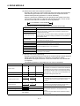
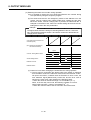
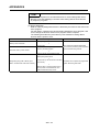
2.3
Differences Between The REAL and VIRTUAL Modes
Portions of the positioning data, positioning device, and servo programs, etc., used
in REAL mode operations are different when used in VIRTUAL mode operations.
The Motion Controller (SV13/22 REAL Mode) Programming Manual (type A273UH
CPU/A173UHCPU(-S1)) should be read after acquainting yourself with these
differences.
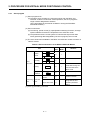
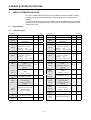
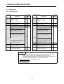
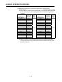
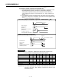
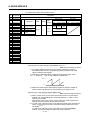
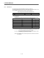
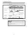
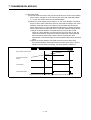
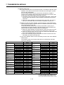
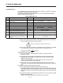
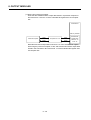
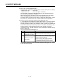
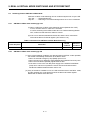
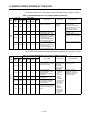
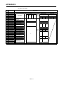
2.3.1
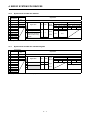
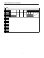
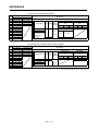
Positioning data
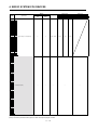
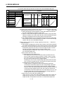
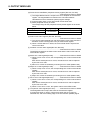
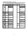
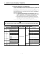
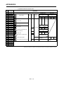
Positioning data used in the VIRTUAL mode is shown in Table 2.1 below.
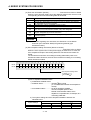
Table 2.1 Positioning Data List
Item
REAL Mode
VIRTURL Mode
System settings
!
!
Fixed parameters
!
∆
Servo parameters
!
!
Parameter block
!
∆
Zeroing data
!
−
JOG operation data
!
−
Limit switch output data
!
∆
Remarks
System-of-units varies
according to the output
module used
Use of "PULSE"only
[!]:Used [ ]:Conditional use [−]:Not used
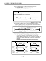
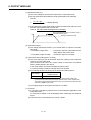
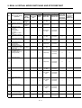
2.3.2
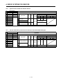
Positioning device
The operating ranges of VIRTUAL mode positioning devices are shown in Tables
2.2 below.
Table 2.2 Operating Range of Positioning Devices
Device Name
Internal relays
REAL Mode
VIRTURL Mode
M2000 to M3839
M2000 to M5487
Special relays
M9073 to M9079
Data registers
D0 to D799
Special registers
D0 to D1559
D9180 to D9199
2−6
2. PROCEDURE FOR VIRTUAL MODE POSITIONING CONTROL
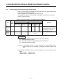
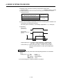
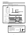
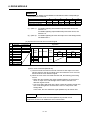
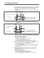
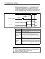
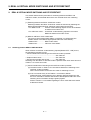
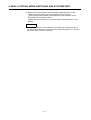
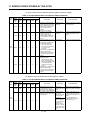
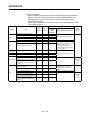
2.3.3
Servo program
(1) Servo program area
(a) The same servo program No. cannot be used in both the REAL and
VIRTUAL modes. For VIRTUAL mode operations, the servo program's
range must be designated in advance.
(The range setting is executed at an IBM PC running the SW2SRXGSV22PE software.)
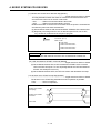
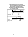
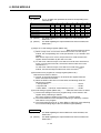
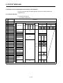
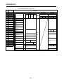
(2) Servo instructions
(a) The zeroing, speed control (II), speed/position switching functions, and highspeed oscillation functions are inoperative in the VIRTUAL mode.
(b) The parameter block's control system-of-units and the torque limit value
items (positioning data designated by the servo program) are not used.
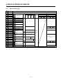
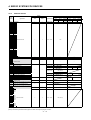
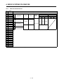
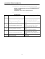
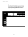
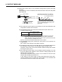
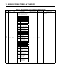
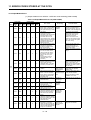
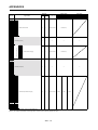
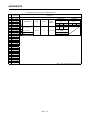
(3) The servo instructions available in the REAL and VIRTUAL modes are shown in
Table 2.3 below.
Table 2.3 Servo Instruction List for REAL & VIRTUAL Modes
REAL VIRTURL
Item
Speed/
VPF
position
VPR
control
Servo
Mode
Mode
!
×
!
×
Remarks
VPSTART
Speed
VVF
control(II)
VVR
Switch to VIRTUAL
instruction
Zeroing
ZERO
!
×
mode after zeroing has
been executed in the
REAL mode
High-speed
oscillation
OSC
Control system-
Positioning Parameter
data
block
of-units
!
×
!
−
!
−
Fixed as "PULSE"
Designated at drive
Torque limit value
module's parameter
setting
[!]:Used [×]:Unusable [−]:Not used
2−7
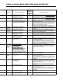
2. PROCEDURE FOR VIRTUAL MODE POSITIONING CONTROL
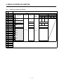
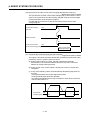
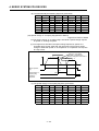
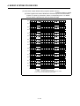
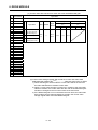
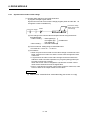
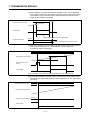
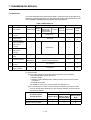
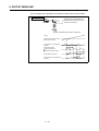
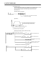
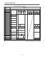
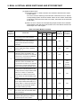
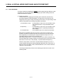
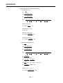
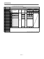
2.3.4
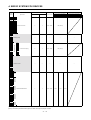
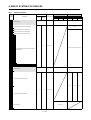
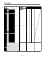
Control change (current value change & speed change)
When a control change is executed in the VIRTUAL mode, the drive module's feed
current value and speed will change.
Control changes are not possible for the output module.
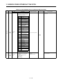
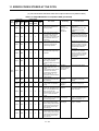
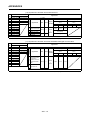
The differences between control changes in the REAL and VIRTUAL modes are
shown in Table 2.4 below.
Table 2.4 Control Changes in the REAL & VIRTUAL Modes
VIRTUAL Mode
Item
REAL
Mode
Drive Module
Output Module
VIRTUAL
Synchronous
Servo motor
Encoder
Roller
Ball
Rotary
Screw
Table
Remarks
Cam
The programming method for a
Current
value
!
∆
!
×
×
×
change
Speed
change
∆
synchronous encoder "current
value change" is different
(See Appendix 10.1.1)
!
×
!
×(Note)
REMARK
(1) The [!], [∆], [×] symbols used in Table 2.4 indicate the following.
•[!] : Setting/execution possible
•[∆] : Execution possible, but programming method is different
•[×] : Setting/execution impossible
(2) (Note): If the output module is a roller which uses a speed change gear, a
speed change can be executed by changing the speed change gear
ratio.
(3) For details regarding the drive and output modules, refer to the sections shown
below.
• Drive module : Chapters 5 & 6
• Output module : Chapters 5 & 8
2−8
3. PERFORMANCE SPECIFICATIONS
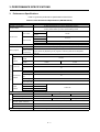
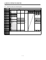
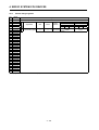
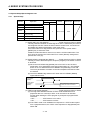
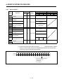
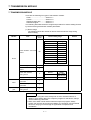
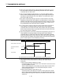
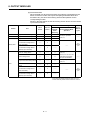
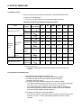
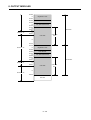
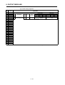
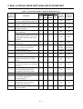
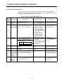
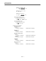
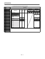
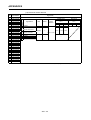
3. Performance Specifications
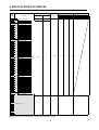
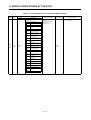
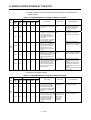
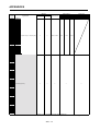
Table 3.1 gives the performance specifications of the PCPU.
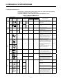
Table 3.1 PCPU Performance Specifications (VIRTUAL Mode)
Item
A273UHCPU
Number of control axes
A173UHCPU
A173UHCPU-SI
32 axes (simultaneous:2 to 4-axes, independent:32-axes)
Synchronous control, PTP(point to point), speed control, fixed-pitch feed, constant-speed
control, position follow-up control, speed switching control
Control modes
Virtual servo motor
Drive module
Roller
Control units
Output module
Programming language
Capacity
Servo program
PULSE
Synchronous
encoder
mm⋅inch
Ball screw
Rotary table
Fixed as "degree"
Cam
mm⋅inch⋅PULSE
Dedicated instructions (servo programs + mechanical system programs)
14k steps (14334 steps) * Capacity matching the servo program for the REAL mode
Approx. 100 points/axis
Number of points
(These values vary depending on the programs. Positioning data can be designated
for positioning
indirectly.)
Number of modules that can be set per CPU
Mechanical system program
Drive
modules
Virtual axes
Transmission
modules
VIRTUAL
module
Synchronous
encoder
12-axes
32
Auxiliary input
axis
32
Gear
64
Clutch
64
Speed change
gear
64
Differential gear
32
Differential gear
for the main shaft
32
32
Ball screw
32
Rotary table
32
Cam
32
Program setting method
Types
Total of 32
Setting with an IBM PC, running the SW2SRX-GSV22PE software
Max. 256
Max. 64
Resolution per cycle
Cam
4- axes
Main shaft
Roller
Output
modules
32-axes
Memory capacity
Storage memory for cam data
and cam rotation mode limit
132k bytes
Approx. 32k bytes
Approx. 132k bytes
(Note-1)
Strocked in block from No.10 of the memory cassette
Stroke resolution
expansion file resister area.
32767
Control mode
Cam data setting method
Max. 256
256⋅512⋅1024⋅2048
Two-way cam/feed cam
Setting with an IBM PC, running the SW0IX-CAMPE software
3−1
3. PERFORMANCE SPECIFICATIONS
Table 3.1 PCPU Performance Specifications (VIRTUAL Mode) (Continued)
Item
A273UHCPU
Interpolation functions
Method
Positioning
Position command
Speed command
Virtual servo motor
A173UHCPU-SI
Linear interpolation (2 to 4-axes), circular interpolation (2-axes)
PTP (point to point), speed control, fixed-pitch feed, constant-speed control, position follow-up
control
Control modes
Acceleration/
deceleration
control
A173UHCPU
Automatic
trapezoidal
acceleration/
deceleration
PTP
:Selection of absolute data method or incremental method
Fixed pitch feed
:Selection of incremental method
Constant speed control :The absolute method and incremental method can be used together
Position follow-up control :Absolute data method
Address setting range
Acceleration−fixed
acceleration/deceleration
1 to 10000000 (PLS/s)
Time−fixed acceleration/deceleration
Acceleration time: 1 to 65535 ms
Acceleration/deceleration time: 1 to 5000 ms
(Only constant-speed control is possible)
Deceleration time: 1 to 65535 ms
S-curve
acceleration/
deceleration
S-curve ratio setting: 0 to 100%
JOG operation function
M-function
−2147483648 to 2147483648 (PLS)
Speed setting range
Provided
M-code output function provided, and M-code completion wait function provided
Skip function
Provided
• A maximum of three manual pulse
• A maximum of three manual pulse
generator can be connected.
generator can be connected.
• One A172SENC is required per piece.
• A maximum of three manual pulse
Manual pulse generator operation
• A maximum of three manual pulse
generators can be operated.
generators can be operated.
function(test mode only)
• Setting of magnification : 1 to 100. It is
• Setting of magnification : 1 to 100. It is
possible to set the smoothing
possible to set the smoothing
magnification.
magnification.
Number of output points
Limit
Number of ON/OFF setting
switch
points
output
function Control mode
High-speed reading
of designated data
Number of input
points (Note-2)
Data latch
timing
Absolute position system
8 points/axis
10 points/axis
Real current value mode/Cam axis current value in one revolution mode
Max. 11 points
(TRA input of A273EX (3 point) + one motion
slot PLC input module (8 points))
Max. 9 points
(TRA input of A172SENC (1 point) + one
motion slot PLC input module (8 points))
At leading edge of the TRA input signal
Within 0.8ms of the signal leading edge for the PLC input module
Made compatible by fitting battery to servo amplifier.
(Possible to select the absolute method or incremental method for each axis)
(Note-1) When the cam is used in the virtual mode, only the following memory cassettes are usable.
For A273UHCPU
• A3NMCA16 (128k bytes)
• A3NMCA24 (192k bytes)
• A3NMCA40 (320k bytes)
• A3NMCA56 (448k bytes)
• A3AMCA96 (768k bytes)
Note that the A3NMCA16 is unusable when cam axis one-revolution mode limit switch output is provided in the virtual mode of
SV22. (The A3NMCA24 or higher is required.)
(Note-2) When a TRA input signal is used as an "External input mode clutch" the high speed reading function can not be used.
3−2
4. SERVO SYSTEM CPU DEVICES
4.
SERVO SYSTEM CPU DEVICES
The servo system CPU devices for which positioning control is carried out using
the VIRTUAL mode and the applications of these devices are explained in this
chapter.
The signals which are sent from the PCPU to the SCPU indicate the PCPU device
refresh cycle and the signals sent from the SCPU to the PCPU indicate the PCPU
device fetch cycle.
4.1
Internal Relays
4.1.1
Internal relay list
A273UHCPU
A173UHCPU(-SI)
Virtual
Device Number
Application
M0
User device (2000 points)
Device Number
Application
M0
User device (2000 points)
M2000
Common device
(320 points)
!
!
M2000
M2320
Unusable (80 points)
M2320
M2400
Axis status
(20 points × 32 axes)
Real mode ...... Axis
Real
(! Valid)
!
!
M2400
M3040
Virtual mode ... Output module
M3040
M3200
Unusable (160 points)
Axis command signal
(20 points × 32 axes)
Real mode ...... Axis
(! Valid)
Real
Virtual
Common device
(320 points)
!
!
Unusable (80 points)
!
!
!
!
Axis status
(20 points × 32 axes)
Real mode ...... Axis
Virtual mode ... Output module
Unusable (160 points)
Axis command signal
(20 points × 32 axes)
!
!
M3200
M3840
Unusable (60 points)
M4000
(Note-1)
Virtual servo motor axis
status
(20 points × 32 axes)
(Note-2)
Backup
!
Synchronous encoder axis
status
(4 points × 4 axes)
!
!
Virtual mode ... Output module
Real mode ...... Axis
Virtual mode ... Output module
M3840
Unusable (60 points)
M4000
(Note-1)
Virtual servo motor axis
status
(20 points × 32 axes)
(Note-2)
M4640
(Note-1)
Synchronous encoder axis
status
(4 points × 12 axes)
!
!
M4640
(Note-1)
M4688
(Note-1)
Unusable (112 points)
M4656
(Note-1)
Unusable (144 points)
M4800
(Note-1)
Virtual servo motor axis
command signal
(20 points × 32 axes)
(Note-2)
M4800
(Note-1)
Virtual servo motor axis
command signal
(20 points × 32 axes)
(Note-2)
×
!
Synchronous encoder axis
command signal
(4 points × 4 axes)
×
×
M5440
(Note-1)
!
M5440
(Note-1)
Synchronous encoder axis
command signal
(4 points × 12 axes)
M5456
(Note-1)
Unusable (32 points)
M5488
(Note-1)
Unusable (113 points)
M5600
M8191
User device (2704 points)
User device (2592 points)
M5488
(Note-1)
M8191
Backup
×
!
!
!
4−1
4. SERVO SYSTEM CPU DEVICES
POINTS
(Note-1) : When the VIRTUAL mode is used do not set M4000 to M5599 in
the latch range.
(Note-2) : The virtual servo motor axis status signals/command signals
occupy only the areas of the axes set in the mechanical system
program. The area of an axis that is not set in the mechanical
system program can be used by the user.
• Total number of points for the user devices
4592 points
4−2
4. SERVO SYSTEM CPU DEVICES
4.1.2
Axis statuses
Axis
Device Number
No.
1
M2400 to M2419
2
M2420 to M2439
3
M2440 to M2459
4
M2460 to M2479
5
M2480 to M2499
6
M2500 to M2519
7
M2520 to M2539
8
M2540 to M2559
9
M2560 to M2579
10 M2580 to M2599
11 M2600 to M2619
12 M2620 to M2639
13 M2640 to M2659
14 M2660 to M2679
15 M2680 to M2699
16 M2700 to M2719
17 M2720 to M2739
18 M2740 to M2759
19 M2760 to M2779
20 M2780 to M2799
21 M2800 to M2819
22 M2820 to M2839
23 M2840 to M2859
24 M2860 to M2879
25 M2880 to M2899
26 M2900 to M2919
27 M2920 to M2939
28 M2940 to M2959
29 M2960 to M2979
Signal Name
(! Valid)
Virtual
Signal Name
Real
Roller
Refresh Cycle
Fetch Cycle
Signal Preset number of axes (Note) Preset number of axes (Note)
Rotary
Cam Direction 1 to 8 9 to 18 19 to 32 1 to 8 9 to 18 19 to 32
Ball
screw
table
1 to 12 13 to24 25 to 32 1 to 12 13 to 24 25 to 32
Positioning start
0 completion
OFF
1 Positioning completion
2 In-position
!
3 Command in-position
4 Speed controlling
3.5ms
7.1ms
14.2ms
3.5ms
7.1ms
14.2ms
OFF
Speed/position change
5 latch
6 Zero pass
7 Error detection
8 Servo error detection
9 Zeroing request
Immediately
!
3.5ms
SCPU
←
PCPU
10 Zeroing completion
11 External signal FLS
12 External signal RLS
13 External signal STOP
!
7.1ms
10ms
3.5ms
14.2ms
20ms
7.1ms
10ms
14.2ms
20ms
External signal
14 DOG/CHANGE
15 Servo ON/OFF status
16 Torque limiting signal
3.5ms
17 DOG/CHANGE signal
Virtual mode continuation
18 operation warning signal
!
19 M-code outputting signal
!
7.1ms
10ms
OFF
30 M2980 to M2999
31 M3000 to M3019
32 M3020 to M3039
(Note): Upper: A273UHCPU, lower: A173UHCPU(-S1)
4-3
14.2ms
20ms
4. SERVO SYSTEM CPU DEVICES
4.1.3
Axis command signal
Axis
Device Number
No.
1
M3200 to M3219
2
M3220 to M3239
3
M3240 to M3259
4
M3260 to M3279
5
M3280 to M3299
6
M3300 to M3319
7
M3320 to M3339
8
M3340 to M3359
9
M3360 to M3379
10 M3380 to M3399
11 M3400 to M3419
12 M3420 to M3439
13 M3440 to M3459
14 M3460 to M3479
15 M3480 to M3499
16 M3500 to M3519
17 M3520 to M3539
18 M3540 to M3559
19 M3560 to M3579
20 M3580 to M3599
21 M3600 to M3619
22 M3620 to M3639
23 M3640 to M3659
24 M3660 to M3679
25 M3680 to M3699
26 M3700 to M3719
Signal Name
(! Valid)
Virtual
Signal Name
Real
Ball
screw
Roller
Refresh Cycle
Fetch Cycle
Signal Preset number of axes (Note) Preset number of axes (Note)
Rotary
Cam Direction 1 to 8 9 to 18 19 to 32 1 to 8 9 to 18 19 to 32
table
1 to 12 13 to 24 25 to 32 1 to 12 13 to24 25 to 32
0 Stop command
1 Sudden stop command
2 Forward rotation JOG start
3 Reverse rotation JOG start
×
Completion signal OFF
4 command
Speed/position change
5 enable
!
6 Limit switch output enable
7 Error reset
!
8 Servo error reset
Start-time stop
9 input/disable
×
3.5ms
10 Unusable
11 Unusable
Feed current value update
12 command
!
×
Address clutch reference
13 setting
Cam reference position
14 setting
×
×
7.1ms
10ms
SCPU
→
PCPU
At switching from real to
virtual
!
×
!
15 Servo OFF
16 Unusable
!
!
17 Unusable
18 Unusable
30 M3780 to M3799
31 M3800 to M3819
19 FIN signal
!
×
27 M3720 to M3739
28 M3740 to M3759
29 M3760 to M3779
14.2ms
32 M3820 to M3839
(Note): Upper: A273UHCPU, lower: A173UHCPU(-S1)
4-4
3.5ms
7.1ms
14.2ms
4. SERVO SYSTEM CPU DEVICES
4.1.4
Virtual servo motor axis statuses
Axis
Device Number
No.
1
M4000 to M4019
2
M4020 to M4039
3
M4040 to M4059
4
M4060 to M4079
5
M4080 to M4099
6
M4100 to M4119
7
M4120 to M4139
8
M4140 to M4159
9
M4160 to M4179
10 M4180 to M4199
11 M4200 to M4219
12 M4220 to M4239
13 M4240 to M4259
14 M4260 to M4279
15 M4280 to M4299
Signal Name
(! Valid)
Refresh Cycle
Signal Name
Positioning start
0 completion
!
1 Positioning completion
2 Unusable
3 Command in-position
4 Speed controlling
!
5 Unusable
6 Unusable
9 Unusable
10 Unusable
11 Unusable
20 M4380 to M4399
21 M4400 to M4419
22 M4420 to M4439
23 M4440 to M4459
24 M4460 to M4479
25 M4480 to M4499
26 M4500 to M4519
1 to 8
3.5ms
9 to 18 19 to 32 1 to 8
14.2ms
3.5ms
7.1ms
14.2ms
Immediately
SCPU
←
PCPU
Backup
12 Unusable
13 Unusable
7.1ms
!
7 Error detection
8 Unusable
17 M4320 to M4339
19 M4360 to M4379
Virtual
Fetch Cycle
Preset number of axes (Note) Preset number of axes (Note)
9 to 18 19 to 32
1 to 12 13 to 24 25 to 32 1 to 12 13 to24 25 to 32
16 M4300 to M4319
18 M4340 to M4359
Real
Signal
Direction
14 Unusable
15 Unusable
16 Unusable
17 Unusable
18 Unusable
19 M-code outputting signal
!
27 M4520 to M4539
28 M4540 to M4559
29 M4560 to M4579
30 M4580 to M4599
31 M4600 to M4619
32 M4620 to M4639
(Note): Upper: A273UHCPU, lower: A173UHCPU(-S1)
4-5
3.5ms
7.1ms
14.2ms
4. SERVO SYSTEM CPU DEVICES
4.1.5
Virtual servo motor axis command signals
Axis
Device Number
No.
1
M4800 to M4819
2
M4820 to M4839
3
M4840 to M4859
4
M4860 to M4879
5
M4880 to M4899
6
M4900 to M4919
7
M4920 to M4939
8
M4940 to M4959
9
M4960 to M4979
Signal Name
(! Valid)
Refresh Cycle
Signal Name
Real
Virtual
0 Stop command
1 Sudden stop command
2 Forward rotation JOG start
3 Reverse rotation JOG start
14 M5060 to M5079
6 Unusable
7 Error reset
×
!
15 M5080 to M5099
8 Unusable
16 M5100 to M5119
17 M5120 to M5139
Start-time stop
9 input/disable
×
!
18 M5140 to M5159
10 Unusable
×
!
11 Unusable
20 M5180 to M5199
12 Unusable
13 Unusable
24 M5260 to M5279
25 M5280 to M5299
26 M5300 to M5319
27 M5320 to M5339
9 to 18 19 to 32
OFF
14 Unusable
15 Unusable
7.1ms
14.2ms
10ms
13 M5040 to M5059
23 M5240 to M5259
9 to 18 19 to 32 1 to 8
!
5 Unusable
19 M5160 to M5179
signal
×
11 M5000 to M5019
22 M5220 to M5239
1 to 8
3.5ms
12 M5020 to M5039
21 M5200 to M5219
Fetch Cycle
Preset number of axes (Note) Preset number of axes (Note)
1 to 12 13 to24 25 to 32 1 to 12 13 to24 25 to 32
Completion
4 command
10 M4980 to M4999
Signal
Direction
10ms
20ms
SCPU
→
PCPU
At start
16 Unusable
17 Unusable
18 Unusable
19 FIN signal
28 M5340 to M5359
29 M5360 to M5379
30 M5380 to M5399
31 M5400 to M5419
32 M5420 to M5439
(Note): Upper: A273UHCPU, lower: A173UHCPU(-S1)
4-6
3.5ms
7.1ms
14.2ms
4. SERVO SYSTEM CPU DEVICES
4.1.6
Synchronous encoder axis statuses
Device Number
Axis
A173UHCPU
No. A273UHCPU
Signal Name
(-S1)
1
M4640 to M4643 M4640 to M4643
2
M4644 to M4647 M4644 to M4647
3
M4648 to M4651 M4648 to M4651
4
M4652 to M4655 M4652 to M4655
5
M4656 to M4659
6
M4660 to M4663
0 Error detection
7
M4664 to M4667
1 External signal TRA
8
M4668 to M4671
9
M4672 to M4675
10
M4676 to M4679
11
M4680 to M4683
12
M4684 to M4687
(! Valid)
Refresh Cycle
Signal Name
Real
Virtual
Fetch Cycle
Signal
Preset number of axes (Note) Preset number of axes (Note)
Direction 1 to 8 9 to 18 19 to 32 1 to 8 9 to 18 19 to 32
1 to 12 13 to 24 25 to 32 1 to 12 13 to 24 25 to 32
Virtual mode continuation
2
operation disable warning
3 Unusable
Immediately
!
!
SCPU
←
PCPU
10ms
20ms
(Note): Upper: A273UHCPU, lower: A173UHCPU(-S1)
4.1.7
Synchronous encoder axis command signals
Device Number
Axis
A173UHCPU
No. A273UHCPU
Signal Name
(-S1)
1
M5440 to M5443 M5440 to M5443
2
M5444 to M5447 M5444 to M5447
3
M5448 to M5451 M5448 to M5451
4
M5452 to M5455 M5452 to M5455
5
M5456 to M5459
6
M5460 to M5463
0 Error reset
7
M5464 to M5467
1 Unusable
8
M5468 to M5471
2 Unusable
9
M5472 to M5475
3 Unusable
10
11
M5476 to M5479
12
M5484 to M5487
(! Valid)
Refresh Cycle
Signal Name
Real
Fetch Cycle
Preset number of axes (Note) Preset number of axes (Note)
Signal
VirtualL
Direction 1 to 8 9 to 18 19 to 32 1 to 8 9 to 18 19 to 32
1 to 12 13 to 24 25 to 32 1 to 12 13 to 24 25 to 32
×
!
M5480 to M5483
(Note): Upper: A273UHCPU, lower: A173UHCPU(-S1)
4-7
10ms
SCPU
→
PCPU
20ms
4. SERVO SYSTEM CPU DEVICES
4.1.8
Common devices
(! Valid)
Device
Number
Signal Name
Signal Direction
Real
Virtual
19 to 32
25 to 32
!
!
SCPU←PCPU
10ms
SCPU→PCPU
SCPU←PCPU
M2042
M2043
M2044
M2045
M2046
M2047
M2048
M2049
M2050
M2051
M2052
M2053
M2054
M2055
All-axis servo ON command
Real/virtual mode change request
Real/virtual mode change status
Real/virtual mode change error detection
Out-of-sync warning
Motion slot fault detection flag
JOG simultaneous start command
All-axis servo ON acceptance flag
Start buffer full
Manual pulse generator 1 enable flag
Manual pulse generator 2 enable flag
Manual pulse generator 3 enable flag
Axis 1
Axis 2
Axis 3
Axis 4
Axis 5
Axis 6
Axis 7
Axis 8
Speed changing flag
Axis 9
Axis 10
Axis 11
Axis 12
Axis 13
Axis 14
Axis 15
Axis 16
9 to 18
13 to 24
SCPU←PCPU
System setting error flag
Unusable (2 points)
1 to 8
1 to 12
!
Speed change point designation flag
M2058
M2059
M2060
M2061
M2062
M2063
M2064
M2065
M2066
M2067
M2068
M2069
M2070
M2071
M2072
M2073
M2074
M2075
M2076
19 to 32
25 to 32
!
M2041
M2057
9 to 18
13 to 24
SCPU→PCPU
Unusable (5 points)
Cam/limit switch output data batch-change request
flag
Cam/limit switch output data batch-change
completion flag
Cam/limit switch output data batch-change error flag
1 to 8
1 to 12
!
PLC ready flag
Axis 1
Axis 2
Axis 3
Axis 4
Axis 5
Axis 6
Axis 7
Axis 8
Axis 9
Axis 10
Axis 11
Axis 12
Axis 13
Axis 14
Axis 15
Axis 16
Start acceptance flag
Axis 17
Axis 18
Axis 19
Axis 20
Axis 21
Axis 22
Axis 23
Axis 24
Axis 25
Axis 26
Axis 27
Axis 28
Axis 29
Axis 30
Axis 31
Axis 32
Unusable (1 point)
Personal computer link communication error flag
Unusable (2 points)
Fetch Cycle
Preset number of axes (Note-1)
!
M2000
M2001
M2002
M2003
M2004
M2005
M2006
M2007
M2008
M2009
M2010
M2011
M2012
M2013
M2014
M2015
M2016
M2017
M2018
M2019
M2020
M2021
M2022
M2023
M2024
M2025
M2026
M2027
M2028
M2029
M2030
M2031
M2032
M2033
M2034
M2035
M2036
M2037
M2038
M2039
M2040
M2056
Refresh Cycle
Preset number of axes (Note-1)
10ms
10ms
!
SCPU→PCPU
At start
END
SCPU→PCPU
!
20ms
3.5ms
7.1ms
14.2ms
END (Note-2)
10ms
SCPU←PCPU
SCPU→PCPU
!
×
SCPU→PCPU
10ms
20ms
10ms
20ms
END (Note-2)
SCPU→PCPU
!
!
SCPU←PCPU
END (Note-2)
!
!
SCPU←PCPU
END (Note-2)
(Note-1): Upper: A273UHCPU, lower: A173UHCPU(-S1)
(Note-2): The refresh cycle "END"s in the longer time of "50ms" and "sequence program scan time".
4 -8
4. SERVO SYSTEM CPU DEVICES
(! Valid)
Device
Number
Axis 17
Axis 18
Axis 19
Axis 20
Axis 21
Axis 22
Axis 23
Axis 24
Axis 25
Axis 26
Axis 27
Axis 28
Axis 29
Axis 30
Axis 31
Axis 32
Speed changing flag
Unusable (8 points)
Synchronous encoder
M2077
M2078
M2079
M2080
M2081
M2082
M2083
M2084
M2085
M2086
M2087
M2088
M2089
M2090
M2091
M2092
M2093
M2094
M2095
M2096
M2097
M2098
M2099
M2100
M2101
M2102
M2103
M2104
M2105
M2106
M2107
M2108
M2109
M2110
M2111
M2112
M2113
M2114
M2115
M2116
M2117
M2118
M2119
M2120
M2121
M2122
M2123
M2124
M2125
M2126
M2127
M2128
M2129
M2130
M2131
M2132
M2133
M2134
M2135
M2136
M2137
M2138
M2139
M2140
M2141
M2142
M2143
M2144
M2145
M2146
M2147
M2148
M2149
M2150
M2151
M2152
M2153
M2154
M2155
M2156
M2157
Signal Name
Axis 1
Axis 2
Axis 3
Axis 4
Axis 5
Axis 6
Axis 7
Axis 8
Axis 9
Axis 10
Axis 11
Axis 12
Current value changing
Unusable (15 points)
Axis 1
Axis 2
Axis 3
Axis 4
Axis 5
Axis 6
Axis 7
Axis 8
Axis 9
Axis 10
Axis 11
Axis 12
Axis 13
Axis 14
Axis 15
Automatically decelerating flag
Axis 16
Axis 17
Axis 18
Axis 19
Axis 20
Axis 21
Axis 22
Axis 23
Axis 24
Axis 25
Axis 26
Axis 27
Axis 28
Axis 29
Axis 30
Refresh Cycle
Fetch Cycle
Signal Direction
Preset number of axes (Note-1)
1 to 8
9 to 18
19 to 32
1 to 12
13 to 24
25 to 32
Preset number of axes (Note-1)
1 to 8
9 to 18
19 to 32
1 to 12
13 to 24
25 to 32
Real
Virtual
!
!
SCPU←PCPU
END (Note-2)
×
!
SCPU←PCPU
END (Note-2)
!
!
SCPU←PCPU
(Note-1): Upper: A273UHCPU, lower: A173UHCPU(-S1)
(Note-2): The refresh cycle "END"s in the longer time of "50ms" and "sequence program scan time"
4 -9
3.5ms
7.1ms
14.2ms
4. SERVO SYSTEM CPU DEVICES
(! Valid)
M2158
M2159
M2160
M2161
M2162
M2163
M2164
M2165
M2166
M2167
M2168
M2169
M2170
M2171
M2172
M2173
M2174
M2175
M2176
M2177
M2178
M2179
M2180
M2181
M2182
M2183
M2184
M2185
M2186
M2187
M2188
M2189
M2190
M2191
M2192
M2193
M2194
M2195
M2196
M2197
M2198
M2199
M2200
M2201
M2202
M2203
M2204
M2205
M2206
M2207
M2208
M2209
M2210
M2211
M2212
M2213
M2214
M2215
M2216
M2217
M2218
M2219
M2220
M2221
M2222
M2223
M2224
M2225
M2226
M2227
M2228
M2229
M2230
M2231
M2232
M2233
M2234
M2235
M2236
M2237
M2238
M2239
Signal Name
Axis 31
Automatically decelerating flag
Axis 32
Output Main shaft side
axis 1 Auxiliary input axis side
Output Main shaft side
axis 2 Auxiliary input axis side
Output Main shaft side
axis 3 Auxiliary input axis side
Output Main shaft side
axis 4 Auxiliary input axis side
Output Main shaft side
axis 5 Auxiliary input axis side
Output Main shaft side
axis 6 Auxiliary input axis side
Output Main shaft side
axis 7 Auxiliary input axis side
Output Main shaft side
axis 8 Auxiliary input axis side
Output Main shaft side
axis 9 Auxiliary input axis side
Output Main shaft side
axis 10 Auxiliary input axis side
Output Main shaft side
axis 11 Auxiliary input axis side
Output Main shaft side
axis 12 Auxiliary input axis side
Output Main shaft side
axis 13 Auxiliary input axis side
Output Main shaft side
axis 14 Auxiliary input axis side
Output Main shaft side
axis 15 Auxiliary input axis side
Output Main shaft side
axis 16 Auxiliary input axis side
Output Main shaft side
axis 17 Auxiliary input axis side
Output Main shaft side
axis 18 Auxiliary input axis side
Output Main shaft side
axis 19 Auxiliary input axis side
Output Main shaft side
axis 20 Auxiliary input axis side
Output Main shaft side
axis 21 Auxiliary input axis side
Output Main shaft side
axis 22 Auxiliary input axis side
Output Main shaft side
axis 23 Auxiliary input axis side
Output Main shaft side
axis 24 Auxiliary input axis side
Output Main shaft side
axis 25 Auxiliary input axis side
Output Main shaft side
axis 26 Auxiliary input axis side
Output Main shaft side
axis 27 Auxiliary input axis side
Output Main shaft side
axis 28 Auxiliary input axis side
Output Main shaft side
axis 29 Auxiliary input axis side
Output Main shaft side
axis 30 Auxiliary input axis side
Output Main shaft side
axis 31 Auxiliary input axis side
Output Main shaft side
axis 32 Auxiliary input axis side
Signal Direction
Clutch status
Device
Number
Unusable (16 points)
Real
Virtual
!
!
Backup
!
SCPU←PCPU
(Note-1): Upper: A273UHCPU, lower: A173UHCPU(-S1)
(Note-2): The refresh cycle "END"s in the longer time of "50ms" and "sequence program scan time"
4 - 10
Refresh Cycle
Preset number of axes (Note-1)
1 to 8
9 to 18
19 to 32
1 to 12
13 to 24
25 to 32
3.5ms
7.1ms
Fetch Cycle
Preset number of axes (Note-1)
1 to 8
9 to 18
19 to 32
1 to 12
13 to24
25 to 32
14.2ms
4. SERVO SYSTEM CPU DEVICES
(! Valid)
Device
Number
M2240
M2241
M2242
M2243
M2244
M2245
M2246
M2247
M2248
M2249
M2250
M2251
M2252
M2253
M2254
M2255
M2256
M2257
M2258
M2259
M2260
M2261
M2262
M2263
M2264
M2265
M2266
M2267
M2268
M2269
M2270
M2271
M2272
M2273
M2274
M2275
M2276
M2277
M2278
M2279
M2280
M2281
M2282
M2283
M2284
M2285
M2286
M2287
M2288
M2289
M2290
M2291
M2292
M2293
M2294
M2295
M2296
M2297
M2298
M2299
M2300
M2301
M2302
M2303
M2304
M2305
M2306
M2307
M2308
M2309
M2310
M2311
M2312
M2313
M2314
M2315
M2316
M2317
M2318
M2319
Signal Name
Axis 1
Axis 2
Axis 3
Axis 4
Axis 5
Axis 6
Axis 7
Axis 8
Axis 9
Axis 10
Axis 11
Axis 12
Axis 13
Axis 14
Axis 15
Axis 16
Axis 17
Axis 18
Axis 19
Axis 20
Axis 21
Axis 22
Axis 23
Axis 24
Axis 25
Axis 26
Axis 27
Axis 28
Axis 29
Axis 30
Axis 31
Axis 32
Speed change "0" accepting flag
Unusable (48 points)
Signal Direction
Real
Virtual
!
!
SCPU←PCPU
(Note-1): Upper: A273UHCPU, lower: A173UHCPU(-S1)
(Note-2): The refresh cycle "END"s in the longer time of "50ms" and "sequence program scan time"
4 - 11
Refresh Cycle
Preset number of axes (Note-1)
1 to 8
9 to 18
19 to 32
1 to 12
13 to 24
25 to 32
3.5ms
7.1ms
Fetch Cycle
Preset number of axes (Note-1)
1 to 8
9 to 18
19 to 32
1 to 12
13 to 24
25 to 32
14.2ms
4. SERVO SYSTEM CPU DEVICES
(1)PLC READY flag (M2000)................................. Signal sent from SCPU to PCPU
(a) This signal notifies the PCPU that SCPU operation is normal. It is switched
ON and OFF by the sequence program.
1) When M2000 is ON, positioning or zeroing (REAL mode only) functions
can be executed by the servo program specified by the sequence
program, and JOG operations can be executed by the sequence
program.
2) When a TEST mode has been established ("M9075" TEST mode in
progress flag is ON) from a peripheral device, the functions described at
item (1) above will be inoperative even if M2000 is switched ON.
(b) The fixed parameters, servo parameters, and limit switch output parameters
can only be changed using a peripheral device when M2000 is OFF.
If an attempt is made to change this data while M2000 is ON, an error will
occur.
(c) When M2000 is switched from OFF to ON, the following processing occurs.
1) Processing details
• The servo parameters are transferred to the servo amplifier.
• The M-code storage area for all axes is cleared.
• The default value of 300% is set in the torque limit value storage area.
• The PCPU READY completed flag (M9074) is turned ON.
2) If there is an axis currently being driven, an error occurs, and the
processing in (1), (c) above is not executed.
3) While the test mode is in effect, the processing in (1), (c) above is not
executed.
When the test mode is cancelled, the processing in (1), (c) will be
executed if M2000 is ON.
V
Start of positioning
Deceleration to stop
t
ON
PLC ready flag
(M2000)
PCPU READY completed flag
(M9074)
OFF
ON
OFF
Servo parameters set in the servo
amplifiers Clearance of M-codes
4 − 12
The PCPU READY completed flag
(M9074) does not come ON because
deceleration is in progress.
4. SERVO SYSTEM CPU DEVICES
(d) When M2000 turns OFF, the following processing is executed.
1) Processing details
• The PCPU READY flag (M9074) is turned OFF.
• Operating axes are decelerated to a stop.
POINT
The PLC READY flag (M2000) switches OFF when a servo system CPU
"STOP" status exists. When the RUN status is resumed, the status which
existed prior to the STOP will be re-established.
ON
M2000
OFF
RUN→STOP switching
STOP→RUN switching
(2) Virtual servomotor START accept flags (M2001 to M2032)
................................................................................ Signals from PCPU to SCPU
(a) The START accept flag switches ON when the sequence program's
positioning START instruction (SVST) is executed, and should be used for
SVST enabled/disabled interlock purposes.
SVST instruction execution request
M 2001
M 2003
SVST instruction execution enabled/
disabled determination
SVST
J1J3
K1
Axis No.1 START Axis No.3 START
accept flag
accept flag
(b) START accept flag ON/OFF processing occurs as shown below.
1) When the sequence program's SVST instruction is executed, the
START accept flag for the axis specified by the SVST instruction
switches ON, and the switches OFF when positioning is completed. The
START accept flag also switches OFF if positioning is stopped before
completion.
(The START accept flag ON, when positioning is stopped before
completion by the speed change for speed “0”.)
When positioning is completed normally
V
When positioning is stopped before completion
Dwell time
V
t
Positioning completed
SVST
instruction
SVST
instruction
ON
START
accept flag
Positioning
START
completed
signal
ON
START
accept flag
OFF
Positioning
completed
signal
Positioning
START
Positioning
completed
signal
ON
OFF
OFF
Positioning
OFF
START
completed signal
OFF
4 − 13
ON
t
In-progress
STOP
completed
4. SERVO SYSTEM CPU DEVICES
2) When executing positioning by switching the JOG instruction ON, the
START accept flag will switch OFF when positioning is stopped by a
JOG instruction OFF.
3) The START accept flag is ON when the manual pulse generator is
enabled (M2051 to M2053:ON), and is OFF when the manual pulse
generator is disabled (M2051 to M2053:OFF).
4) The START accept flag is ON during a current value change being
executed by a sequence program CHGA instruction.
The START accept flag will switch OFF when the current value change
is completed.
CHGA instruction
OFF at current value change
completion
ON
START accept flag OFF
Current value
change processing
5) When M2000 is OFF, execution of a SVST instruction causes the start
accept flag to come ON; the flag goes OFF when M2000 comes ON.
ON
PLC READY (M2000)
OFF
SVST instruction
ON
START accept flag
OFF
CAUTION
The user must not turn start accept flags ON/OFF.
• If a start accept flag that is ON is switched OFF with the sequence program or a peripheral
device, no error will occur but the positioning operation will not be reliable.
Depending on the type of machine, it might operate in an unanticipated manner.
• If a start accept flag that is OFF is switched ON with the sequence program or a peripheral
device, no error will occur at that time, but the next time an attempt is made to start the axis a
start accept flag ON error will occur and the axis will not start.
4 − 14
4. SERVO SYSTEM CPU DEVICES
(3) PC link communication error flag (M2034)
........................................................................ Signal sent from PCPU to SCPU
This flag comes ON when an error occurs during personal computer linking
communication. When M2034 comes ON the error code is stored in the
personal computer link communication error code storage register (D9196).
The devices dedicated to personal computer communication are indicated
below.
Table 4.1 PC link communication device list
Device Name
Contents
Device Number
PC link
communication error
flag
OFF : No PC link communication error
ON : PC link communication error detected
(Flag changes to OFF if normal communication is
restored.)
M2034
PC link
communication error
codes
00: No error
01: Receiving timing error
02: CRC error
03: Communication response code error
04: Receiving frame error
05: Communication task start error
(Error codes are reset to 00 by normal
communication restart.)
D9196
Table 4.2 PC link communication error code list
Error Codes
stored in D9196
Error Contents
Correction Method
01
PC link communication
receiving packet did not
arrive.
Receiving packet arrival
timing was late.
⋅ Confirm that the personal computer power is
on.
⋅ Check the communication cable connection.
⋅ Check for communication cable burnout.
⋅ Confirm that A30BD-PCF/A30CD-PCF is
properly placed.
02
The receiving packet CRC
code is incorrect.
⋅ Confirm that there is nothing causing noise in
the vicinity.
⋅ Check the communication cable connection.
⋅ Check for communication cable burnout.
03
The receiving packet data ID
is incorrect.
⋅ Confirm that A30BD-PCF/A30CD-PCF is
properly placed.
⋅ Replace the A30BD-PCF/A30CD-PCF.
04
The number of the frame
received is incorrect.
⋅ Check the communication cable connection.
⋅ Check for communication cable burnout.
⋅ Confirm that there is nothing causing noise in
the vicinity.
05
The communication task on
the personal computer side
has not been started.
⋅ Start the communication task on the personal
computer side.
4 − 15
4. SERVO SYSTEM CPU DEVICES
(4) Speed switching point designation flag (M2040)
........................................................................ Signal sent from SCPU to PCPU
The speed switching point designation flag is used when a speed change is
designated at the pass point in constant-speed control.
(a) By turning M2040 ON before the start of constant-speed control (before the
servo program is started using the SVST instruction), control can be
executed with a speed change at the start of the pass point.
M2040 OFF
M2040 ON
V
V
t
Pass points in
constant-speed control
(here, a speed change
is designated at P3)
P1
P2
P3
P4
t
Pass points in
constant-speed control
(here, a speed change
is designated at P3)
P1
P2
P3
P4
ON
Speed switching point
designator flag
Speed switching point
OFF
designator flag
OFF
SVST instruction
SVST instruction
ON
ON
Start accept flag
OFF
Start accept flag
OFF
(b) After completion of start accept processing, the speed switching point
designation flag can be turned OFF at any time.
(5) System setting error flag (M2041)................... Signal sent from PCPU to SCPU
When the power is switched ON, or when the servo system CPU is reset, the
system setting data set with a peripheral device is input, and a check is
performed to determine if the set data matches the module mounting status
(of the CPU base unit and extension base units).
• ON.............. Error
• OFF............ Normal
(a) The ERROR LED on the front of the CPU will switch ON when an error
occurs. Moreover, a log of errors which have occurred can be referred to
at a peripheral device (device running SW2SRX-GSV22PE).
(b) Positioning cannot be started when M2041 is ON. To start the positioning
operation, eliminate the error cause, and either switch the power back ON
or execute a servo system CPU reset.
REMARK
A slot designated as "not used" at the system setting data will be regarded as
"not used" even if loaded with a module.
4 − 16
4. SERVO SYSTEM CPU DEVICES
(6) All-axes servo START command (M2042) ..... Signal sent from SCPU to PCPU
This signal is used to enable servo operation.
• Servo operation ENABLED ............ When M2042 is switched ON, the servo
OFF signal is OFF, and there are no
active servo errors.
• Servo operation DISABLED ........... When M2042 switches ON, the servo
OFF signal is ON, or a servo error is
detected.
ON
All-axes servo
START command
OFF
ON
All-axes servo
START accept flag
OFF
Servo ON
POINT
Once M2042 is switched ON, it will not switch OFF even if the CPU is stopped.
(7) REAL/VIRTUAL mode switching request flag (M2043)
........................................................................ Signal sent from SCPU to PCPU
This flag is used for switching between the REAL and VIRTUAL modes.
(a) To switch from the REAL to the VIRTUAL mode, turn M2043 ON after the
M9074 PCPU READY flag comes ON.
• An error check occurs when M2043 is switched from OFF to ON.
If no error is detected, switching to the VIRTUAL mode occurs, and the
M2044 REAL/VIRTUAL Mode Determination flag switches ON.
• If an error is detected, switching to the VIRTUAL mode will not occur. In
this case, the M2045 REAL/VIRTUAL Mode Switching Error flag will
switch ON, and the error code will be stored at the D9193 error code
storage error.
(b) To switch from the VIRTUAL to the REAL mode, turn M2043 OFF.
• If an "all-axes stopped" status exists at the virtual servomotors, switching
to the REAL mode will occur, and M2044 will go OFF.
• Switching to the REAL mode will not occur if any of the virtual
servomotor axes are in motion. In this case, M2045 will switch ON, and
an error code will be stored at the D9193 error code storage error.
(c) For details regarding the procedure for switching between the REAL and
VIRTUAL modes, see Chapter 9.
4 − 17
4. SERVO SYSTEM CPU DEVICES
(8) REAL/VIRTUAL mode status flag (M2044)
........................................................................ Signal sent from PCPU to SCPU
This flag verifies that switching between the REAL and VIRTUAL modes is
completed, and verifies the current mode.
• OFF when the REAL mode is in effect, and switching from the VIRTUAL to
REAL mode is completed.
• ON when switching from REAL to VIRTUAL mode is completed.
This flag should be used as an interlock function when executing a servo
program START or a control change (speed change, current value change).
(9) REAL/VIRTUAL mode switching error detection flag (M2045)
....................................................................... Signal sent from PCPU to SCPU
This flag indicates whether or not an error was detected when switching
between the REAL and VIRTUAL modes.
• Remains OFF if no error was detected at mode switching.
• Switches ON if an error was detected at mode switching.
In this case, the error code will be stored at D9193.
(10) Synchronization discrepancy warning flag (M2046)
........................................................................ Signal sent from PCPU to SCPU
(a) This signal switches ON in the VIRTUAL mode when a discrepancy occurs
between the drive module and output module synchronized positions.
This signal status determines whether or not drive module operation can
be resumed after it has stopped.
• M2046 : ON ...............Continued operation disabled
• M2046 : OFF .............Continued operation enabled
(b) The synchronization discrepancy warning flag will switch ON when the
following conditions occur.
• When operation is stopped by an external emergency stop (EMG)
command.
• When a servo error occurs at the output module.
(c) When the synchronization discrepancy warning flag switches ON,
operation can be resumed by the following procedure.
1) Return to the REAL mode and eliminate the error cause.
↓
2) Synchronize the axes.
↓
3) Switch the synchronization discrepancy warning flag (M2046) OFF.
↓
4) Switch to the VIRTUAL mode.
↓
5) Resume operation.
4 − 18
4. SERVO SYSTEM CPU DEVICES
(11) Motion slot module error detection flag (M2047)
........................................................................ Signal sent from PCPU to SCPU
This flag indicates whether the status of modules mounted at the base unit
and extension base units is normal or abnormal.
• ON.............. Status of mounted module is abnormal
• OFF ........... Status of mounted module is normal
Module information is checked for errors both when the power is switched ON
and after the power has been switched ON.
(a) When M2047 switches ON, the A273UHCPU "ERROR" LED switches ON.
(b) Required processing when an error is detected (axis STOP, servo OFF,
etc.) should be conducted at the sequence program.
"SL00 UNIT ERROR"
I/O slot No. (0 to 7)
Base unit No.
0: CPU base
1: Motion extension base 1
2: Motion extension base 2
3: Motion extension base 3
4: Motion extension base 4
POINT
Positioning control will continue even if an error is detected at a motion slot.
(12) JOG simultaneous START command (M2048)
.......................................................................... Signal sent from SCPU to PCPU
(a) When M2048 switches ON, a JOG simultaneous START will occur at the
JOG execution axis (axis-1 to axis-32) designated at the JOG simultaneous
START Axis Area(D710 to D713).
(b) When M2048 switches OFF, the JOG axis motion will decelerate and stop.
(13) All-Axes servo START accept flag (M2049)
.......................................................................... Signal sent from PCPU to SCPU
The all-axes servo START flag indicates that servo operation is possible.
• ON................ Servo is operative.
• OFF .............. Servo is inoperative.
ON
All-axes servo START
Accept flag
OFF
ON
All-axes servo START
command
OFF
Servo ON
4 − 19
4. SERVO SYSTEM CPU DEVICES
(14) START buffer full (M2050) .............................. Signal sent from PCPU to SCPU
(a) This signal switches ON when the PCPU fails to process the specified data
within 65 seconds following a positioning START (SVST) instruction or a
control change (CHGA/CHGV) instruction from the sequence program.
(b) A M2050 reset must be executed from the sequence program.
(15) Manual pulse generator enabled flag (M2051 to 2053)
................................................................................. Signal from SCPU to PCPU
The manual pulse generator flag designates the enabled/disabled status for
positioning executed by pulse inputs from manual pulse generators connected
(Note)
to P1 to P3
of the A273EX or A172SENC.
• ON................ Positioning control by manual pulse generator inputs is enabled.
• OFF .............. Positioning control by manual pulse generator inputs is disabled
(inputs are ignored).
REMARK
(Note): For details on the P1 to P3 connector of the A273EX or A172SENC,
please refer to the Motion Controller A273UHCPU/A173UHCPU
User’s Manual.
(16) Cam data/limit switch output data batch-change request flag (M2056)
................................................................................. Signal from SCPU to PCPU
(a) The cam data/limit switch output data batch-change request flag is used to
change the cam data/limit switch output data imported at power-on or servo
system CPU reset into the other cam data/limit switch output data.
(Cam data/limit switch output data changes are valid in both the real and
virtual modes.)
1) Turning M2056 from OFF to ON causes the cam data/limit switch output
data (limit switch output data in cam axis within-one-revolution current
value mode) which have been written to the extended file registers from
No. 10 on to be imported to the PCPU.
Since the import of cam data is valid on the leading edge (OFF to ON) of
M2056, it cannot be stopped if M2056 is turned OFF during import.
2) Make a reset at normal completion or error detection of the cam data/limit
switch output data import.
• At normal completion ... M2057: ON
• At error detection ..... M2058: ON
(b) Refer to Section 8.4.6 and 8.4.7 for details of cam data/limit switch output
data changes.
4 − 20
4. SERVO SYSTEM CPU DEVICES
(17) Cam data/limit switch output data batch-change completion flag (M2057)
................................................................................. Signal from PCPU to SCPU
(a) This flag is used to confirm normal completion of cam data/limit switch
output data changes.
1) The flag turns ON at normal completion of cam data/limit switch output
data changes.
2) Turning M2056 OFF also turns M2057 OFF.
(b) While cam data/limit switch output data are being imported, the real mode
cannot be switched to the virtual mode.
Use M2056 as an interlock for switching to the virtual mode.
(18) Cam data/limit switch output data batch-change error flag (M2058)
................................................................................. Signal from PCPU to SCPU
(a) This flag is used to check whether an error occurred or not when the cam
data/limit switch output data were changed.
1) The flag remains OFF when there is no cam data/limit switch output data
error.
2) The flag turns ON on detection of a cam data/limit switch output data
error.
(b) Turning M2056 OFF also turns M2058 OFF.
(19) Speed change in progress flag (M2061 to M2092)
........................................................................ Signal sent from PCPU to SCPU
This flag switches ON when a speed change (designated by a control change
(CHGV) instruction at the sequence program) is in progress. This flag should
be used for speed change program interlock purposes.
ON
Speed change command
OFF
Delay due to sequence program
CHGV instruction
ON
Speed change in
progress flag
OFF
13 to 16ms
Speed change
Speed after speed change
Set speed
Speed change completed
4 − 21
4. SERVO SYSTEM CPU DEVICES
(20) Synchronous encoder current value changing flags (M2101 to M2112)
............................................................................. Signals from PCPU to SCPU
The synchronous encoder current value changing flag is ON while the current
value of the synchronous encoder is being changed using the control change
(CHGA) instruction of the sequence program.
Use this flag as an interlock for the synchronous encoder current value
change program.
ON
Current value change
command
OFF
CHGA instruction
ON
Synchronous encoder
OFF
current value changing flag
During current value
change processing
(21) Automatically decelerating flag (M2128 to M2159)
................................................................................Signal from PCPU to SCPU
This signal is ON while automatic deceleration processing is performed under
positioning control or position follow-up control.
(a) Under position follow-up control, this flag is ON during automatic
deceleration to the command address, but turns OFF if the command
address is changed during that time.
(b) Under control in any control system, this flag turns OFF on normal start
completion.
(c) In any of the following cases, the automatically decelerating flag does not
turn ON.
• During deceleration due to JOG signal turned OFF
• During manual pulse generator operation
• At midway deceleration due to stop command or stop cause occurrence
• When travel value is "0"
V
t
ON
Automatically
decelerating flag
4 − 22
OFF
4. SERVO SYSTEM CPU DEVICES
(d) The automatically decelerating flag list is given below.
Axis No. Device No. Axis No. Device No. Axis No. Device No. Axis No. Device No.
1
M2128
9
M2136
17
M2144
25
M2152
2
M2129
10
M2137
18
M2145
26
M2153
3
M2130
11
M2138
19
M2146
27
M2154
4
M2131
12
M2139
20
M2147
28
M2155
5
M2132
13
M2140
21
M2148
29
M2156
6
M2133
14
M2141
22
M2149
30
M2157
7
M2134
15
M2142
23
M2150
31
M2158
8
M2135
16
M2143
24
M2151
32
M2159
(22) Speed change "0" accepting flag (M2240 to M2271)
................................................................................Signal from PCPU to SCPU
(a) The speed change "0" accepting flag is ON while a speed change request
for speed "0" is being accepted.
(b) This signal turns ON when the speed change request for speed "0" is
accepted during a start. After that, this signal turns OFF when a speed
change to other than speed "0" is accepted or on completion of a stop due
to a stop cause.
Decelerated to stop when speed
change "0" is accepted.
Thereafter, restarted when
speed is changed to other than 0.
Speed change "0"
V
V1
Speed change V2
V2
t
Start acceptance
flag
ON
Speed change "0"
accepting flag
OFF
Positioning
completion
(c) The speed change "0" accepting flag list is given below.
Axis No. Device No. Axis No. Device No. Axis No. Device No. Axis No. Device No.
1
M2240
9
M2248
17
M2256
25
M2264
2
M2241
10
M2249
18
M2257
26
M2265
3
M2242
11
M2250
19
M2258
27
M2266
4
M2243
12
M2251
20
M2259
28
M2267
5
M2244
13
M2252
21
M2260
29
M2268
6
M2245
14
M2253
22
M2261
30
M2269
7
M2246
15
M2254
23
M2262
31
M2270
8
M2247
16
M2255
24
M2263
32
M2271
4 − 23
4. SERVO SYSTEM CPU DEVICES
POINT
(1) Even during a stop, the ON status of the start acceptance flag (M2001 to
M2032) indicates that the speed change "0" request is accepted. Check
with this speed change "0" flag.
(2) During interpolation, the flags corresponding to the interpolation axes are
set.
(3) In any of the following cases, the speed change "0" request is invalid.
• After deceleration due to JOG OFF
• During manual pulse generator operation
• After positioning automatic deceleration start
• After deceleration due to stop cause
(d) The flag turns OFF if a speed change request for other than speed "0"
occurs during deceleration to a stop due to speed change "0".
Speed change "0"
V
V1
Speed change V2
V2
t
Start acceptance
flag
ON
Speed change "0"
accepting flag
OFF
(e) The flag turns OFF if a stop cause occurs after speed change "0"
acceptance.
Speed change "0"
V
Stop cause
t
Start acceptance
flag
ON
OFF
Speed change "0"
accepting flag
4 − 24
4. SERVO SYSTEM CPU DEVICES
(f) The speed change "0" accepting flag does not turn ON if a speed change "0"
occurs after an automatic deceleration start.
Automatic deceleration start
V
Speed change "0"
t
Start acceptance
flag
(OFF)
Speed change "0"
accepting flag
(g) Under position follow-up control, the speed change "0" accepting flag turns
ON if a speed change "0" occurs after an automatic deceleration start to the
"specified address".
Automatic deceleration start Speed change "0"
Speed change V2
Command address P1
V
V1
Command address P2
V2
P1
Start acceptance
flag
ON
Speed change "0"
accepting flag
OFF
REMARK
Under position follow-up control, the axis will not start if the "command
address" is changed during speed change "0" acceptance.
4 − 25
P2
t
4. SERVO SYSTEM CPU DEVICES
4.2
Data Registers
4.2.1
Data register list
A273UHCPU
Device
Number
D0
(! Valid)
Application
Real
Axis monitor device
(20 points × 32 axes)
!
Real mode ..........Axis
A173UHCPU (-S1)
Device
Number
Virtual
!
D0
Virtual mode........Output module
D640
D704
Application
Real
Virtual
!
!
Control change register
(2 points × 32axes)
!
!
Common device (96 points)
!
!
Back
up
!
Back
up
!
Axis monitor device
(20 points × 32 axes)
Real mode ..........Axis
Virtual mode........Output module
Control change register
(2 points × 32 axes)
!
!
D640
Common device (96 points)
!
!
D704
Virtual servo motor axis (Note)
monitor device (6 points × 32 axes)
D800
(! Valid)
Virtual servo motor axis (Note)
monitor device (6 points × 32 axes)
D800
Current value after virtual servo
motor axis (Note) main shaft's
differential gear (4 points × 32 axes)
Synchronous encoder axis (Note)
monitor device (6 points × 12 axes)
Back
up
Current value after virtual servo
motor axis (Note) main shaft's
differential gear (4 points × 32 axes)
Synchronous encoder axis (Note)
monitor device (6 points × 4 axes)
!
D1120
D1120
Current value after synchronous
encoder axis main shaft's differential
gear (4 points × 4 axes)
Current value after synchronous
encoder axis main shaft's differential
gear (4 points × 12 axes)
D1240
Cam axis monitor device (Note)
(10 points × 32 axes)
D1600
D1160
Unusable
D1240
Cam axis monitor device (Note)
(10 points × 32 axes)
D1600
User device (6632 points)
User device (6632 points)
D8191
D8191
POINT
(Note): The virtual servo motor axis / synchronous encoder axis / cam axis
monitor device occupy only the areas of the axes set in the
mechanical system program. The area of an axis that is not set in the
mechanical system program can be used by the user.
⋅ Total number of points for the user devices
6632 points
4 − 26
4. SERVO SYSTEM CPU DEVICES
4.2.2
Axis
No.
Axis monitor devices
Device
Number
1
D0 to D19
2
D20 to D39
3
D40 to D59
4
D60 to D79
5
D80 to D99
Signal Name
(! Valid)
Refresh Cycle
Signal Name
Real
Virtual
Signal
Direction
Fetch Cycle
Preset number of axes (Note-1) Preset number of axes (Note-1)
1 to 8
9 to 18 19 to 32 1 to 8
9 to 18 19 to 32
1 to 12 13 to 24 25 to 32 1 to 12 13 to 24 25 to 32
6
D100 to D119
7
8
D120 to D139
D140 to D159
9
10
D160 to D179
D180 to D199
11
12
D200 to D219
D220 to D239
13
14
D240 to D259
D260 to D279
7 Major error code
8 Servo error code
15
16
D280 to D299
D300 to D319
9 Zeroing re-travel value
17
18
D320 to D339
D340 to D359
12 Execution program No.
19
D360 to D379
13 M-code
20
D380 to D399
14 Torque limit value
21
22
D400 to D419
D420 to D439
15
23
D440 to D459
24
D460 to D479
25
D480 to D499
26
D500 to D519
27
D520 to D539
28
29
D540 to D559
D560 to D579
30
31
D580 to D599
D600 to D619
32
D620 to D639
0 Feed current value/roller
1 cycle
2
Real current value
3
3.5ms
6 Minor error code
Data set pointer for
constant-speed control
16 Travel value change
17 register
18 STOP input-time real
19 current value
14.2ms
!
4
Deviation counter value
5
10 Travel value after proximity
11 dog ON
7.1ms
Immediately
SCPU←PCPU 10ms
3.5ms
!
Backup
20ms
7.1ms
14.2ms
END (Note-2)
At start
×
3.5ms
!
7.1ms
14.2ms
At start/during start
×
SCPU→PCPU
Backup
SCPU←PCPU
3.5ms
END (Note-2)
(Note-1): Upper: A273UHCPU, lower: A173UHCPU(-S1)
(Note-2): The refresh cycle "END"s in the longer time of "50ms" and "sequence program scan time".
4 - 27
7.1ms
14.2ms
4. SERVO SYSTEM CPU DEVICES
4.2.3
Control change registers
Axis
No.
Device
Number
1
D640,D641
2
D642,D643
3
D644,D645
4
5
D646,D647
D648,D649
6
D650,D651
7
D652,D653
8
D654,D655
9
10
D656,D657
D658,D659
11
12
D660,D661
D662,D663
13
14
D664,D665
D666,D667
15
16
D668,D669
D670,D671
17
18
D672,D673
D674,D675
19
D676,D677
20
D678,D679
21
22
D680,D681
D682,D683
23
24
D684,D685
D686,D687
25
26
D688,D689
D690,D691
27
28
D692,D693
D694,D695
29
30
D696,D697
D698,D699
31
32
D700,D701
D702,D703
Signal Name
(! Valid)
Refresh Cycle
Signal Name
0
JOG speed setting register
1
Real
Virtual
Signal
Direction
!
!
SCPU→PCPU
(Note-1): Upper: A273UHCPU, lower: A173UHCPU(-S1)
4 - 28
Fetch Cycle
Preset number of axes (Note-1) Preset number of axes (Note-1)
1 to 8 9 to 18 19 to 32 1 to 8 9 to 18 19 to 32
1 to 12 13 to 24 25 to 32 1 to 12 13 to 24 25 to 32
At start
4. SERVO SYSTEM CPU DEVICES
4.2.4
Virtual servo motor axis monitor devices
Axis
No.
Device
Number
1
D800 to D805
2
D810 to D815
3
D820 to D825
4
D830 to D835
5
D840 to D845
6
D850 to D855
7
D860 to D865
0
Feed current value
1
8
D870 to D875
2 Minor error code
9
D880 to D885
3 Major error code
10
D890 to D895
4 Execution program No.
11
D900 to D905
5 M-code
12
13
D910 to D915
14
15
D930 to D935
16
17
D950 to D955
18
D970 to D975
19
D980 to D985
Signal Name
(! Valid)
Refresh Cycle
Signal Name
Real
Virtual
Signal
Direction
Fetch Cycle
Preset number of axes (Note-1) Preset number of axes (Note-1)
1 to 8
9 to 18 19 to 32 1 to 8
9 to 18 19 to 32
1 to 12 13 to 24 25 to 32 1 to 12 13 to 24 25 to 32
3.5ms
Backup
!
SCPU←PCPU
7.1ms
14.2ms
Immediately
At start
3.5ms
D920 to D925
D940 to D945
D960 to D965
20 D990 to D995
21 D1000 to D1005
22 D1010 to D1015
23 D1020 to D1025
24 D1030 to D1035
25 D1040 to D1045
26 D1050 to D1055
27 D1060 to D1065
28 D1070 to D1075
29 D1080 to D1085
30 D1090 to D1095
31 D1100 to D1105
32 D1110 to D1115
(Note-1): Upper: A273UHCPU, lower: A173UHCPU(-S1)
4 - 29
7.1ms
14.2ms
4. SERVO SYSTEM CPU DEVICES
4.2.5
Current values after virtual servo motor axis main shaft's differential gear
Axis
No.
Device
Number
1
D806 to D809
2
D816 to D819
3
D826 to D829
4
D836 to D839
5
D846 to D849
6
7
D856 to D859
8
9
D876 to D879
10
11
D896 to D899
12
D916 to D919
13
D926 to D929
14
D936 to D939
15
D946 to D949
16
D956 to D959
17
D966 to D969
18
D976 to D979
19
D986 to D989
20
D996 to D999
D866 to D869
D886 to D889
D906 to D909
Signal Name
(! Valid)
Refresh Cycle
Signal Name
Real
Virtual
Signal
Direction
Fetch Cycle
Preset number of axes (Note-1) Preset number of axes (Note-1)
1 to 8
9 to 18 19 to 32 1 to 8
9 to 18 19 to 32
1 to 12 13 to 24 25 to 32 1 to 12 13 to 24 25 to 32
Current value after virtual
0
servo motor axis main shaft's
1
differential gear
2 Error search output axis No.
3
Backup
!
Data set pointer for constantspeed control
21 D1006 to D1009
22 D1016 to D1019
23 D1026 to D1029
24 D1036 to D1039
25 D1046 to D1049
26 D1056 to D1059
27 D1066 to D1069
28 D1076 to D1079
29 D1086 to D1089
30 D1096 to D1099
31 D1106 to D1109
32 D1116 to D1119
(Note-1): Upper: A273UHCPU, lower: A173UHCPU(-S1)
4 - 30
SCPU←PCPU 3.5ms
7.1ms
14.2ms
4. SERVO SYSTEM CPU DEVICES
4.2.6
Synchronous encoder axis monitor devices
Axis
Device Number
No.
A273UHCPU
Signal Name
A173UHCPU(-S1)
1
D1120 to D1125 D1120 to D1125
2
D1130 to D1135 D1130 to D1135
3
D1140 to D1145 D1140 to D1145
4
D1150 to D1155 D1150 to D1155
5
D1160 to D1165
6
D1170 to D1175
0
7
D1180 to D1185
1
8
(! Valid)
Signal Name
Real
Signal
Virtual
Direction
Refresh Cycle
Fetch Cycle
Preset number of axes (Note-1)
Preset number of axes (Note-1)
1 to 8
1 to 8
9 to 18 19 to 32
9 to 18 19 to 32
1 to 12 13 to 24 25 to 32 1 to 12 13 to 24 25 to 32
Current value
D1190 to D1195
2 Minor error code
9 D1200 to D1205
3 Major error code
10 D1210 to D1215
4 Unusable
11 D1220 to D1225
5 Unusable
3.5ms
Backup
!
SCPU
←
PCPU
7.1ms
14.2ms
Immediately
12 D1230 to D1235
(Note-1): Upper: A273UHCPU, lower: A173UHCPU(-S1)
4.2.7
Current values after synchronous encoder axis main shaft's differential gear
Axis
Device Number
No.
A273UHCPU
1
D1126 to D1129 D1126 to D1129
2
D1136 to D1139 D1136 to D1139
3
D1146 to D1149 D1146 to D1149
4
D1156 to D1159 D1156 to D1159
5
D1166 to D1169
6
D1176 to D1179
7
D1186 to D1189
8
D1196 to D1199
9 D1206 to D1209
10 D1216 to D1219
11 D1226 to D1229
Signal Name
A173UHCPU(-S1)
(! Valid)
Signal Name
Real
Signal
Virtual
Direction
Refresh Cycle
Fetch Cycle
Preset number of axes (Note-1)
Preset number of axes (Note-1)
1 to 8
1 to 8
9 to 18 19 to 32
9 to 18 19 to 32
1 to 12 13 to 24 25 to 32 1 to 12 13 to 24 25 to 32
Current value after
0
synchronous encoder axis
1
main shaft's differential gear Backup
2
!
Error detection output axis
SCPU
←
PCPU
3.5ms
7.1ms
No.
3 Unusable
12 D1236 to D1239
(Note-1): Upper: A273UHCPU, lower: A173UHCPU(-S1)
4 - 31
14.2ms
4. SERVO SYSTEM CPU DEVICES
4.2.8
Axis
No.
Cam axis monitor devices
Device
Number
Signal Name
1 D1240 to D1249
(! Valid)
Refresh Cycle
2 D1250 to D1259
3 D1260 to D1269
4 D1270 to D1279
Signal Name
Real
Virtual
Signal
Direction
5 D1280 to D1289
0 Unusable
7 D1300 to D1309
1 Execution cam No.
2
Execution stroke value
3
9 D1320 to D1329
10 D1330 to D1339
1 to 8
9 to 18 19 to 32 1 to 8
9 to 18 19 to 32
1 to 12 13 to 24 25 to 32 1 to 12 13 to 24 25 to 32
6 D1290 to D1299
8 D1310 to D1319
Fetch Cycle
Preset number of axes (Note-1) Preset number of axes (Note-1)
11 D1340 to D1349
4 Cam axis current value
5 within one revolution
12 D1350 to D1359
6 Unusable
13 D1360 to D1369
7 Unusable
14 D1370 to D1379
8 Unusable
15 D1380 to D1389
9 Unusable
Backup
!
3.5ms
7.1ms
SCPU←PCPU
16 D1390 to D1399
17 D1400 to D1409
18 D1410 to D1419
19 D1420 to D1429
20 D1430 to D1439
21 D1440 to D1449
22 D1450 to D1459
23 D1460 to D1469
24 D1470 to D1479
25 D1480 to D1489
26 D1490 to D1499
27 D1500 to D1509
28 D1510 to D1519
29 D1520 to D1529
30 D1530 to D1539
31 D1540 to D1549
32 D1550 to D1559
(Note-1): Upper: A273UHCPU, lower: A173UHCPU(-S1)
4 - 32
14.2ms
4. SERVO SYSTEM CPU DEVICES
4.2.9
Common devices
(! Valid)
Device
Number
D704
D705
D706
D707
D708
D709
D710
D711
D712
D713
D714
D715
D716
D717
D718
D719
D720
D721
D722
D723
D724
D725
D726
D727
D728
D729
D730
D731
D732
D733
D734
D735
D736
D737
D738
D739
D740
D741
D742
D743
D744
D745
D746
D747
D748
D749
D750
D751
D752
D753
D754
D755
D756
D757
D758
D759
D760
D761
D762
D763
D764
D765
D766
D767
D768
D769
D770
D771
D772
D773
D774
D775
D776
D777
D778
D779
D770
D781
D782
D783
D784
D785
D786
D787
D788
D789
D790
D791
D792
D793
D794
D795
D796
D797
D798
D799
Refresh Cycle
Preset number of axes (Note-1)
Signal Name
Signal Direction
Real
Virtual
Unusable (6 points)
Fetch Cycle
Preset number of axes (Note-1)
1 to 8
9 to 18
19 to 32
1 to 8
9 to 18
19 to 32
1 to 12
13 to 24
25 to 32
1 to 12
13 to 24
25 to 32
JOG operation simultaneous start axis setting register
At start
Manual pulse generator axis 1 No. setting register
Manual pulse generator axis 2 No. setting register
Manual pulse generator axis 3 No. setting register
Axis 1
Axis 2
Axis 3
Axis 4
Axis 5
Axis 6
Axis 7
Axis 8
Axis 9
Axis 10
Axis 11
Axis 12
Axis 13
Axis 14
Axis 15
Axis 16 Manual pulse generator's one-pulse input magnification
Axis 17 setting register
Axis 18
Axis 19
Axis 20
Axis 21
Axis 22
Axis 23
Axis 24
Axis 25
Axis 26
Axis 27
Axis 28
Axis 29
Axis 30
Axis 31
Axis 32
Manual pulse generator 1 smoothing magnification setting register
Manual pulse generator 2 smoothing magnification setting register
Manual pulse generator 3 smoothing magnification setting register
!
!
SCPU→PCPU
At manual PG enable leading edge
Unusable (5 points)
Limit switch output disable setting register
3.5ms
!
!
SCPU←PCPU
Limit switch output status storage register
At power ON
Servo amplifier type
(Note-1): Upper: A273UHCPU, lower: A173UHCPU(-S1)
4 - 33
7.1ms
14.2ms
4. SERVO SYSTEM CPU DEVICES
(1) JOG operation simultaneous start axis setting registers (D710 to D713)
.................................................................................... Data from SCPU to PCPU
(a) These registers are used to set the virtual servomotor axis No. and
directions of the axis whose JOG operation will be started simultaneously.
b15 b14 b13 b12 b11 b10 b9 b8 b7 b6 b5 b4 b3 b2 b1 b0
Axis Axis Axis Axis Axis Axis Axis Axis Axis Axis Axis Axis Axis Axis Axis
D710 Axis
16
15
14
13
12
11
10
9
8
7
6
5
4
3
2
1
D711
Axis Axis Axis Axis Axis Axis Axis Axis Axis Axis Axis Axis Axis Axis Axis Axis
32
31
30
29
28
27
26
25
24
23
22
21
20
19
18
17
Axis Axis Axis Axis Axis Axis Axis Axis Axis Axis Axis Axis Axis Axis Axis
D712 Axis
16
15
14
13
12
11
10
9
8
7
6
5
4
3
2
1
Axis Axis Axis Axis Axis Axis Axis Axis Axis Axis Axis Axis Axis Axis Axis
D713 Axis
32
31
30
29
28
27
26
25
24
23
22
21
20
19
18
17
Forward
rotation
JOG
Reverse
rotation
JOG
Make JOG operation simultaneous start axis setting with 1/0.
1 : Simultaneous start executed
0 : Simultaneous start not executed
(b) If "1" is set to both in the forward and reverse rotation JOG start bits of the
same axis No., the corresponding axis results in a minor error and makes a
forward rotation JOG start.
(c) Refer to Section 7.19.3 of the Motion Controller (SV13/SV22 REAL Mode)
programming manual (type A273UH/A173UH) for details of simultaneous
JOG operation start.
(2) Manual pulse generator-controlled axis No. setting registers (D714 to D719)
................................................................................... Data from SCPU to PCPU
(a) These registers store the virtual servomotor axis No. which will be controlled
by manual pulse generators.
P1
b15 b14 b13 b12 b11 b10 b9 b8 b7 b6 b5 b4 b3 b2 b1 b0
Axis Axis Axis Axis Axis Axis Axis Axis Axis Axis Axis Axis Axis Axis Axis
D714 Axis
16
15
14
13
12
11
10
9
8
7
6
5
4
3
2
1
Axis Axis Axis Axis Axis Axis Axis Axis Axis Axis Axis Axis Axis Axis Axis Axis
31
30
29
28
27
26
25
24
23
22
21
20
19
18
17
D715 32
P2
Axis Axis Axis Axis Axis Axis Axis Axis Axis Axis Axis Axis Axis Axis Axis
D716 Axis
16
15
14
13
12
11
10
9
8
7
6
5
4
3
2
1
Axis Axis Axis Axis Axis Axis Axis Axis Axis Axis Axis Axis Axis Axis Axis
D717 Axis
32
31
30
29
28
27
26
25
24
23
22
21
20
19
18
17
D718
Axis Axis Axis Axis Axis Axis Axis Axis Axis Axis Axis Axis Axis Axis Axis Axis
16
15
14
13
12
11
10
9
8
7
6
5
4
3
2
1
D719
Axis Axis Axis Axis Axis Axis Axis Axis Axis Axis Axis Axis Axis Axis Axis Axis
32
31
30
29
28
27
26
25
24
23
22
21
20
19
18
17
P3
Make manual pulse generator-controlled axis setting with 1/0.
1 : Specified axis
0 : Unspecified axis
(b) Refer to Section 7.20 of the Motion Controller (SV13/SV22 REAL Mode)
programming manual (type A273UH/A173UH) for details of manual pulse
generator operation.
4 − 34
4. SERVO SYSTEM CPU DEVICES
(3) Manual pulse generator 1-pulse input magnification setting registers
(D720 to D751)............................................................ Data from SCPU to PCPU
(a) This register is used to set the magnification (1 to 100) per pulse of the input
pulse count from the manual pulse generator for manual pulse generator
operation.
1-Pulse Input
Magnification
Setting Register
Correspondi
ng Axis No.
Axis 1
D736
Axis 17
Axis 2
D737
Axis 18
D722
Axis 3
D738
Axis 19
D723
Axis 4
D739
Axis 20
D724
Axis 5
D740
Axis 21
D725
Axis 6
D741
Axis 22
D726
Axis 7
D742
Axis 23
D727
Axis 8
D743
Axis 24
D728
Axis 9
D744
Axis 25
D729
Axis 10
D745
Axis 26
D730
Axis 11
D746
Axis 27
D731
Axis 12
D747
Axis 28
D732
Axis 13
D748
Axis 29
D733
Axis 14
D749
Axis 30
D734
Axis 15
D750
Axis 31
D735
Axis 16
D751
Axis 32
1-Pulse Input
Magnification
Setting Register
Correspondin
g Axis No.
D720
D721
Setting
Range
1 to 100
Setting
Range
1 to 100
(b) Refer to Section 7.20 of the Motion Controller (SV13/SV22 REAL Mode)
programming manual (type A273UH/A173UH) for details of manual pulse
generator operation.
4 − 35
4. SERVO SYSTEM CPU DEVICES
(4) Manual pulse generator smoothing magnification setting area
(D752 to D754) ...................................................... Data from SCPU to PCPU
(a) These devices are used to set the smoothing time constants of manual
pulse generators.
Manual Pulse Generator Smoothing
Magnification Setting Register
Setting Range
Manual pulse generator 1 (P1) : D752
0 to 59
Manual pulse generator 2 (P2) : D753
Manual pulse generator 3 (P3) : D754
(b) When the smoothing magnification is set, the smoothing time constant is as
indicated by the following expression.
Smoothing time constant (t) = (smoothing magnification + 1) × 56.8 [ms]
(c) Operation
Manual pulse
generator input
ON
Manual pulse
generator enable flag
(M2051)
OFF
V
V1
t
t
t
t
Output speed (V1) = (number of input pulses/ms) × (manual pulse
generator 1-pulse input magnification setting)
Travel value (L) = (travel value per pulse) × number of input pulses ×
(manual pulse generator 1-pulse input magnification
setting)
REMARK
1) The travel value per pulse of the manual pulse generator is as indicated
below.
• Setting unit
mm
: 0.1µm
inch
: 0.00001inch
degree : 0.00001degree
PULSE : 1 PLS
2) The smoothing time constant is 56.8ms to 3408ms.
4 − 36
4. SERVO SYSTEM CPU DEVICES
(5) Limit switch output disable setting registers (D760 to D775)
.................................................................................... Data from SCPU to PCPU
(a) These registers are used to disable the external outputs of the limit switch
outputs on a point by point basis. Set the corresponding bit to 1 to disable
the limit switch output and turn OFF the external output.
b15 b14 b13 b12 b11 b10 b9 b8 b7 b6 b5 b4 b3 b2 b1 b0
D760 LY0F LY0E LY0D LY0C LY0B LY0A LY09 LY08 LY07 LY06 LY05 LY04 LY03 LY02 LY01 LY00
For axis 2
For axis 1
D761 LY1F LY1E LY1D LY1C LY1B LY1A LY19 LY18 LY17 LY16 LY15 LY14 LY13 LY12 LY11 LY10
For axis 4
For axis 3
D762 LY2F LY2E LY2D LY2C LY2B LY2A LY29 LY28 LY27 LY26 LY25 LY24 LY23 LY22 LY21 LY20
For axis 6
For axis 5
D763 LY3F LY3E LY3D LY3C LY3B LY3A LY39 LY38 LY37 LY36 LY35 LY34 LY33 LY32 LY31 LY30
For axis 8
For axis 7
D764 LY4F LY4E LY4D LY4C LY4B LY4A LY49 LY48 LY47 LY46 LY45 LY44 LY43 LY42 LY41 LY40
For axis 10
For axis 9
D765 LY5F LY5E LY5D LY5C LY5B LY5A LY59 LY58 LY57 LY56 LY55 LY54 LY53 LY52 LY51 LY50
For axis 12
For axis 11
D766 LY6F LY6E LY6D LY6C LY6B LY6A LY69 LY68 LY67 LY66 LY65 LY64 LY63 LY62 LY61 LY60
For axis 14
For axis 13
D767 LY7F LY7E LY7D LY7C LY7B LY7A LY79 LY78 LY77 LY76 LY75 LY74 LY73 LY72 LY71 LY70
For axis 16
For axis 15
D768 LY8F LY8E LY8D LY8C LY8B LY8A LY89 LY88 LY87 LY86 LY85 LY84 LY83 LY82 LY81 LY80
For axis 18
For axis 17
D769 LY9F LY9E LY9D LY9C LY9B LY9A LY99 LY98 LY97 LY96 LY95 LY94 LY93 LY92 LY91 LY90
For axis 20
For axis 19
D770 LYAF LYAE LYAD LYAC LYAB LYAA LYA9 LYA8 LYA7 LYA6 LYA5 LYA4 LYA3 LYA2 LYA1 LYA0
For axis 22
For axis 21
D771 LYBF LYBE LYBD LYBC LYBB LYBA LYB9 LYB8 LYB7 LYB6 LYB5 LYB4 LYB3 LYB2 LYB1 LYB0
For axis 24
For axis 23
D772 LYCF LYCE LYCD LYCC LYCB LYCA LYC9 LYC8 LYC7 LYC6 LYC5 LYC4 LYC3 LYC2 LYC1 LYC0
For axis 26
For axis 25
D773 LYDF LYDE LYDD LYDC LYDB LYDA LYD9 LYD8 LYD7 LYD6 LYD5 LYD4 LYD3 LYD2 LYD1 LYD0
For axis 28
For axis 27
D774 LYEF LYEE LYED LYEC LYEB LYEA LYE9 LYE8 LYE7 LYE6 LYE5 LYE4 LYE3 LYE2 LYE1 LYE0
For axis 30
For axis 29
D775 LYFF LYFE LYFD LYFC LYFB LYFA LYF9 LYF8 LYF7 LYF6 LYF5 LYF4 LYF3 LYF2 LYF1 LYF0
For axis 32
For axis 31
1) Specify 1 or 0 to set each bit.
1: Disable ..... Limit switch output remains OFF.
0: Enable ...... Limit switch output turns ON/OFF based on set data.
2) "LY" in LY00 to LYFF indicates limit switch output.
4 − 37
4. SERVO SYSTEM CPU DEVICES
(6) Limit switch output status storage registers (D776 to D791)
.................................................................................... Data from PCPU to SCPU
(a) The output states (ON/OFF) of the limit switch outputs set on the peripheral
device and output to the A1SY42 and the AY42 are stored in terms of 1 and
0.
• ON .................. 1
• OFF................. 0
(b) These registers can be used to export the limit switch output data in the
sequence program, for example.
b15 b14 b13 b12 b11 b10 b9 b8 b7 b6 b5 b4 b3 b2 b1 b0
D776 LY0F LY0E LY0D LY0C LY0B LY0A LY09 LY08 LY07 LY06 LY05 LY04 LY03 LY02 LY01 LY00
For axis 2
For axis 1
D777 LY1F LY1E LY1D LY1C LY1B LY1A LY19 LY18 LY17 LY16 LY15 LY14 LY13 LY12 LY11 LY10
For axis 4
For axis 3
D778 LY2F LY2E LY2D LY2C LY2B LY2A LY29 LY28 LY27 LY26 LY25 LY24 LY23 LY22 LY21 LY20
For axis 6
For axis 5
D779 LY3F LY3E LY3D LY3C LY3B LY3A LY39 LY38 LY37 LY36 LY35 LY34 LY33 LY32 LY31 LY30
For axis 8
For axis 7
D780 LY4F LY4E LY4D LY4C LY4B LY4A LY49 LY48 LY47 LY46 LY45 LY44 LY43 LY42 LY41 LY40
For axis 10
For axis 9
D781 LY5F LY5E LY5D LY5C LY5B LY5A LY59 LY58 LY57 LY56 LY55 LY54 LY53 LY52 LY51 LY50
For axis 12
For axis 11
D782 LY6F LY6E LY6D LY6C LY6B LY6A LY69 LY68 LY67 LY66 LY65 LY64 LY63 LY62 LY61 LY60
For axis 14
For axis 13
D783 LY7F LY7E LY7D LY7C LY7B LY7A LY79 LY78 LY77 LY76 LY75 LY74 LY73 LY72 LY71 LY70
For axis 16
For axis 15
D784 LY8F LY8E LY8D LY8C LY8B LY8A LY89 LY88 LY87 LY86 LY85 LY84 LY83 LY82 LY81 LY80
For axis 18
For axis 17
D785 LY9F LY9E LY9D LY9C LY9B LY9A LY99 LY98 LY97 LY96 LY95 LY94 LY93 LY92 LY91 LY90
For axis 20
For axis 19
D786 LYAF LYAE LYAD LYAC LYAB LYAA LYA9 LYA8 LYA7 LYA6 LYA5 LYA4 LYA3 LYA2 LYA1 LYA0
For axis 22
For axis 21
D787 LYBF LYBE LYBD LYBC LYBB LYBA LYB9 LYB8 LYB7 LYB6 LYB5 LYB4 LYB3 LYB2 LYB1 LYB0
For axis 24
For axis 23
D788 LYCF LYCE LYCD LYCC LYCB LYCA LYC9 LYC8 LYC7 LYC6 LYC5 LYC4 LYC3 LYC2 LYC1 LYC0
For axis 26
For axis 25
D789 LYDF LYDE LYDD LYDC LYDB LYDA LYD9 LYD8 LYD7 LYD6 LYD5 LYD4 LYD3 LYD2 LYD1 LYD0
For axis 28
For axis 27
D790 LYEF LYEE LYED LYEC LYEB LYEA LYE9 LYE8 LYE7 LYE6 LYE5 LYE4 LYE3 LYE2 LYE1 LYE0
For axis 30
For axis 29
D791 LYFF LYFE LYFD LYFC LYFB LYFA LYF9 LYF8 LYF7 LYF6 LYF5 LYF4 LYF3 LYF2 LYF1 LYF0
For axis 32
For axis 31
1 or 0 is stored into each bit of D776 to D791.
ON ........1
OFF.......0
REMARK
LY in LY
of D776 to D791 indicates limit switch output.
4 − 38
4. SERVO SYSTEM CPU DEVICES
(7) Servo amplifier type (D792 to D799) .......................... Data from PCPU to SCPU
The servo amplifier types set in system settings are stored when the servo
system CPU control power supply is switched on or reset.
b15 to b12 b11 to b8 b7 to b4 b3 to b1
D792
Axis 4
Axis 3
Axis 2
Axis 1
D793
Axis 8
Axis 7
Axis 6
Axis 5
D794
Axis 12
Axis 11
Axis 10
Axis 9
D795
Axis 16
Axis 15
Axis 14
Axis 13
D796
Axis 20
Axis 19
Axis 18
Axis 17
D797
Axis 24
Axis 23
Axis 22
Axis 21
D798
Axis 28
Axis 27
Axis 26
Axis 25
D799
Axis 32
Axis 31
Axis 30
Axis 29
Servo amplifier type
0 ..... Unused axis
1 ..... ADU (CPU base)
2 ..... MR- -B
5 ..... ADU (motion extension base)
4 − 39
4. SERVO SYSTEM CPU DEVICES
4.3 Special Relays/Special Registers List
4.3.1
Special relays
Device No.
Signal Name
M9073
PCPU WDT error flag
M9074
PCPU READY completed flag
M9075
TEST mode ON flag
M9076
External emergency stop input
flag
M9077
Manual pulse generator axis
setting error flag
M9078
TEST mode request flag
M9079
Servo program setting error flag
! Valid)
(!
REAL
VIRTUAL
Signal
Direction
Refresh Cycle
!
!
SCPU←PCPU
END
Fetch Cycle
(1) PCPU WDT error flag (M9073)......................... Signal sent from PCPU to SCPU
This flag switches ON when a "watchdog timer error" is detected by the PCPU's
self- diagnosis function. When the PCPU detects a WDT error, it executes an
immediate stop without deceleration of the driven axes.
If the PCPU WDT error flag switches ON, press the servo system CPU's
[RESET] key to execute a reset.
If M9073 remains ON after a reset occurs, there is a PCPU malfunction. The
error cause is stored in the "PCPU WDT error cause (D9184)" storage area
(see Section 4.3.2 (2)).
(2) PCPU READY completed flag (M9074) ............ Signal sent from PCPU to SCPU
This flag is used to determine (at the sequence program) if the PCPU is normal
or abnormal.
(a) When the PLC READY flag (M2000) turns from OFF to ON, the fixed
parameters, servo parameters, limit switch output data, etc., are checked,
and if no error is detected the PCPU READY-completed flag comes ON.
The servo parameters are written to the servo amplifiers and the M-codes
are cleared.
(b) The PCPU READY flag switches OFF when the PLC READY (M2000)
signal switches OFF.
PLC READY
(M2000)
t
PCPU READY
completion
(M9074)
Servo parameters are written to the servo
amplifier, and M-codes are cleared.
(3) TEST mode ON flag (M9075) ........................... Signal sent from PCPU to SCPU
(a) This flag status indicates whether a TEST mode established from a
peripheral device is currently in effect. It can be used as an interlock
function when starting the servo program by a sequence program SVST
instruction.
• OFF................... TEST mode is not in effect.
• ON .................... TEST mode is in effect.
(b) If the TEST mode is not established in response to a TEST mode request
from a peripheral device, the "TEST mode request error flag (M9078)" will
switch ON.
4 − 40
4. SERVO SYSTEM CPU DEVICES
(4) External emergency stop input flag (M9076)
.......................................................................... Signal sent from PCPU to SCPU
This flag status indicates whether the external emergency stop input to the
power module's EMG terminal is ON or OFF.
• OFF .............. External emergency stop input is ON.
• ON ................ External emergency stop input is OFF.
(5) Manual Pulse Generator Axis Setting Error Flag (M9077)
.......................................................................... Signal sent from PCPU to SCPU
(a) This flag indicates whether the setting designated at the manual pulse
generator axis setting register (D714 to D719) is normal or abnormal.
• OFF................... All D714 to D719 settings are normal.
• ON .................... At least one D714 to D719 setting is abnormal.
(b) When M9077 switches ON, the error content is stored at the manual pulse
generator axis setting error register (D9187).
(6) TEST Mode Request Error Flag (M9078) ......... Signal sent from PCPU to SCPU
(a) This flag switches ON if the TEST mode is not established in response to a
TEST mode request from a peripheral device.
(b) When M9078 switches ON, the error content is stored at the manual pulse
generator axis setting error register (D9188).
(7) Servo Program Setting Error Flag (M9079) ...... Signal sent from PCPU to SCPU
This flag status indicates whether the positioning data at the servo program
designated by the SVST instruction is normal or abnormal.
• OFF .............. Normal
• ON ................ Abnormal
The content of a servo program error is stored at D9189 and D9190.
4 − 41
4. SERVO SYSTEM CPU DEVICES
4.3.2
Special registers
! Valid)
(!
Device
Number
D9180
D9181
D9182
Signal Name
Unusable
D9183
Test mode request error
information
D9184
PCPU WDT error factor
D9185
D9186
D9187
Error program No.
D9190
Error item information
D9191
Servo amplifier loading
information
D9194
D9195
D9196
Real/virtual mode change
error information
Refresh Cycle
Fetch Cycle
Preset number of axes (Note)
Preset number of axes (Note)
1 to 8
9 to18
19 to 32
1 to 8
9 to18
19 to 32
1 to 12
13 to 24
25 to 32
1 to 12
13 to 24
25 to 32
At test mode request
!
!
At PCPU WDT error
occurrence
SCPU←PCPU
At manual PG enable
leading edge
Unusable
D9189
D9193
Virtual
Manual pulse generator axis
setting error information
D9188
D9192
Real
Signal
Direction
At start
At servo amplifier power-on
!
!
SCPU←PCPU
At real/virtual mode change
Personal computer link
communication error code
3.5ms
7.1ms
14.2ms
D9197
D9198
Unusable
D9199
(Note): Upper: A273UHCPU, lower: A173UHCPU(-S1)
(1) Test mode request error (D9182, D9183) ................... Data from PCPU to SCPU
When the TEST mode request error flag (M9078) switches ON, the axis data
for axes in motion at that time will be stored.
b15 b14 b13 b12 b11 b10
b9
b8
b7
b6
b5
b4
b3
b2
b1
b0
D9182
Axis16 Axis15 Axis14 Axis13 Axis12 Axis11 Axis10 Axis9 Axis8 Axis7 Axis6 Axis5 Axis4 Axis3 Axis2 Axis1
D9183
Axis32 Axis31 Axis30 Axis29 Axis28 Axis27 Axis26 Axis25 Axis24 Axis23 Axis22 Axis21 Axis20 Axis19 Axis18 Axis17
Stores the operating/stopped
status of each axis
0: Stopped
1: Operating
4 − 42
4. SERVO SYSTEM CPU DEVICES
(2) PCPU WDT error cause(D9184).....................Data from the PCPU to the SCPU
When PCPU error occurs, the code of cause will be stored.
Error Code
1
Error Cause
Operation when Error Occurs
PCPU software fault 1
2
PCPU operation cycle time over
3
PCPU software fault 2
30
PCPU/SCPU hard ware fault
AC servo motor drive module CPU fault
100
Indicates the slot No.(0 to 7)
where the AC motor drive module
with the fault is loaded.
100 to 107
110 to 117
120 to 127
130 to 137
140 to 147
Indicates the stage No. of the base
on which the AC motor drive module
with the fault is loaded.
0: CPU base
1: Extension base 1st stage
2: Extension base 2nd stage
3: Extension base 3rd stage
4: Extension base 4th stage
Hardware fault of module loaded on motion CPU
base unit or extension base unit.
200
200 to 207
210 to 217
220 to 227
230 to 237
240 to 247
Action to Take
All axes stop immediately, after
which operation cannot be
started.
Reset with the reset key.
The servo error detection flag
(M2408+20n) of the
corresponding axis turns ON,
resulting in a servo-off status.
After that, operation is performed
in accordance with "ADU servo
error-time processing setting" in
system settings.
Perform reset with the key.
If the error occurs after reset,
change the ADU module since it
may be faulty.
All axes stop immediately, after
which operation cannot be
started.
Reset with the reset key.
If the error reoccurs after
resetting, the relevant module or
the relevant slot(base unit) is
probably faulty: replace the
module/base unit.
Indicates the slot No.(0 to 7)
where the module with the fault
is loaded.
Indicates the stage No. of the base
on which the module with the fault
is loaded.
0: CPU base
1: Extension base 1st stage
2: Extension base 2nd stage
3: Extension base 3rd stage
4: Extension base 4th stage
Separate servo amplifier (MRhardware fault
-B) interface
250
250 to 253
Faulty SSCNET No.
0: SSCNET 1
1: SSCNET 2
2: SSCNET 3
3: SSCNET 4
300
PCPU software fault 3
Reset with the reset key.
301
8 or more points of CPSTART instruction were
used to start programs in excess of simultaneously
startable programs.
Number of
simultaneously
startable programs
Perform reset with the key.
Use 8 or more points of
CPSTART instruction to start
programs within the number of
simultaneously startable
programs.
Conventional
function version
20
Function added version
14
4 − 43
4. SERVO SYSTEM CPU DEVICES
(3) Manual pulse generator axis setting error information (D9185 to D9187)
................................................................................... Data from PCPU to SCPU
The corresponding axis setting resister (D714 to D719), the smoothing
magnification setting register (D752 to D754) and the manual pulse generator
1-pulse input magnification setting register (D720 to D751) are checked on the
leading edge of the manual pulse generator enable flag (M2051 to M2053), and
if an error is founded, it is stored into manual pulse generator axis setting error
corresponding.
b15 b14 b13 b12 b11 b10
D9185
0
0
0
0
0
0
b9
b8
b7
b6
b5
b4
b3
b2
b1
b0
0
0
0
0
P3
P2
P1
P3
P2
P1
Store the axis setting errors of the manual pulse
generators connected to P1 to P3 of A273EX.
0: Normal
1: Setting error
(Axis setting in each digit is other than 1 to 32)
Store the smoothing magnification setting errors
of the manual pulse generators connected to P1
to P3 of A273EX.
0: Normal
1: Setting error
(Axis setting in each digit is other than 0 to 59)
All turn to 0.
D9186
Axis16 Axis15 Axis14 Axis13 Axis12 Axis11 Axis10
D9187
Axis32 Axis31 Axis30 Axis29 Axis28 Axis27 Axis26 Axis25 Axis24 Axis23 Axis22 Axis21 Axis20 Axis19 Axis18 Axis17
Axis9
Axis8
Axis7
Axis6
Axis5
Axis4
Axis3
Axis2
Axis1
Store the 1-pulse input magnification setting
errors of the axes.
0: Stopping
1: Operating
(Input magnification of each axis is other than
1 to 100)
(4) Error program No. (D9189) .............................Data from the PCPU to the SCPU
(a) When the servo program setting error flag (M9079) switches ON, the
erroneous servo program No. (0 to 4095) will be stored.
(b) If, once an error program number has been stored, an error occurs in
another servo program, the program number of the subprogram with the
new error is stored.
4 − 44
4. SERVO SYSTEM CPU DEVICES
(5) Error item information (D9190) ........................... Data sent from PCPU to SCPU
When the servo program setting error flag (M9079) switches ON, the error code
corresponding to the erroneous setting item will be stored.
Error Code
900
901
902
904
905
906
Error item
data
Error Description
The servo program designated by the SVST instruction does not exist.
The axis No. designated by the SVST instruction is different from the axis
No. designated by the servo program.
The instruction code is unreadable (incorrect code).
A REAL mode servo program was started while in the VIRTUAL mode.
An instruction that cannot be executed in the VIRTUAL mode
(VPF,VPR,VVF,VVR,VPSTART, ZERO, OSC) was designated.
An axis designated as "unused" at the system settings is used in the servo
program designated by the SVST instruction.
A setting item error exists in the servo program designated by the SVST
instruction. (Note)
REMARK
(Note): For details regarding error item data, see Section 6.3 of the Motion
Controller (SV13/22 REAL Mode) Programming Manual (type
A273UH/A173UH).
(6) Servo amplifier loading information (D9191 to D9192)
....................................................................................Data from PCPU to SCPU
When the servo system CPU control power supply is switched on or reset, the
servo amplifier and option slot loading states are checked and its results are
stored.
The axis which turned from non-loading to loading status after power-on is
handled as loaded. However, the axis which turned from loading to non-loading
status remains as loaded.
b15 b14 b13 b12 b11 b10
b9
b8
b7
b6
b5
b4
b3
b2
b1
b0
Axis9
Axis8
Axis7
Axis6
Axis5
Axis4
Axis3
Axis2
Axis1
D9191
Axis16 Axis15 Axis14
Axis13 Axis12
Axis11 Axis10
D9192
Axis32 Axis31 Axis30
Axis29 Axis28
Axis27 Axis26 Axis25
Axis24 Axis23 Axis22
Axis21 Axis20
Axis19 Axis18 Axis17
Sarvo amplifier loading status
Loaded
1
Non-loaded
0
(a) Servo amplifier installation status
1) Installed/not installed status
• "installed" status ................... The MR- -B is normal
(i.e. communication with the servo amplifier is
normal)
• "not installed" status ............. No servo amplifier is installed.
The servo amplifier power is OFF.
Normal communication with the servo
amplifier is not possible due, for example, to a
connecting cable fault.
2) The system settings and servo amplifier installation statuses are
indicated below.
System Settings
Used (axis No. setting)
Unused
ADU
Loaded
1 is stored
0 is stored
4 − 45
Not loaded
Major error
0 is stored
MRLoaded
1 is stored
0 is stored
-B
Not loaded
0 is stored
0 is stored
4. SERVO SYSTEM CPU DEVICES
(7) REAL/VIRTUAL mode switching error information (D9193 to D9195)
.......................................................................... Data sent from PCPU to SCPU
When a mode switching error occurs in real-to -virtual or virtual-to-real mode
switching, or a mode continuation error occurs in the virtual mode, its error
information is stored.
Refer to Section 10.6 for details of the stored error code.
(8) PC link communication error codes (D9196)
........................................................................... Data sent from PCPU to SCPU
One of the following error codes are stored when an error occurs during PC
link communication.
Error Code
stored in
Error Contents
Correction Method
D9196
⋅ Confirm that the personal computer power is on.
01
PC link communication receiving packet did not
⋅ Check the communication cable connection.
arrive.
⋅ Check for communication cable burnout.
Receiving packet arrival timing was late.
⋅ Confirm that A30BD-PCF/A30CD-PCF is properly
placed.
⋅ Confirm that there is nothing causing noise in the
02
The receiving packet CRC code is incorrect.
vicinity.
⋅ Check the communication cable connection.
⋅ Check for communication cable burnout.
⋅ Confirm that A30BD-PCF/A30CD-PCF is properly
03
The receiving packet data ID is incorrect.
placed.
⋅ Replace the A30BD-PCF/A30CD-PCF.
⋅ Check the communication cable connection.
04
The number of the frame received is incorrect.
⋅ Check for communication cable burnout.
⋅ Confirm that there is nothing causing noise in the
vicinity.
05
The communication task on the personal computer ⋅ Start the communication task on the personal
side has not been started.
computer side.
4 − 46
5. MECHANICAL SYSTEM PROGRAM
5 MECHANICAL SYSTEM PROGRAM
This section discusses the VIRTUAL mode's mechanical system program.
This program consists of a mechanical module connection diagram and the
mechanical module parameters.
• The mechanical module connection diagram shows the virtual mechanical
system consisting of connected virtual mechanical modules.
• The mechanical module parameters are the parameters used at the mechanical
module connection diagram for control of the mechanical modules.
For details regarding the mechanical module parameters, refer to the mechanical
module parameter lists shown in Chapters 6 to 8.
5−1
5. MECHANICAL SYSTEM PROGRAM
5.1 Mechanical Module Connection Diagram
The mechanical module connection diagram shows a virtual system consisting of
mechanical modules.
The mechanical module connection configuration is shown in Fig. 5.1 below.
Virtual axis
Indicates rotation direction
Transmission module
Differential
gear
Virtual
servomotor
Gear
Drive module
Synchronous
encoder
Connection shaft
Virtual
servomotor
Synchronous
encoder
Clutch
Virtual auxiliary
input shaft
Transmission module
Drive module
Virtual main shaft
Differential
gear
Gear
Speed change
gear
Speed change
gear
Cam
Synchronous
encoder
Output
shaft
Roller
Ball
screw
Rotary
table
1 block
1 system
Fig. 5.1 Mechanical Module Connection Configuration
POINTS
(1) Either a virtual servomotor or a virtual synchronous encoder can be
connected at the drive module.
(2) One of the following can be connected at the output module:
Cam, roller, ball screw, or rotary table.
5−2
Output module
Clutch
Virtual
servomotor
5. MECHANICAL SYSTEM PROGRAM
(1) Block
The term "block" refers to a single series of elements between and including a
virtual transmission module (gear connected to the virtual main shaft) and an
output module.
Refer to Table 5.1 to determine the number of mechanical modules which can
be connected in one block.
(2) System
The term "system" refers to all the blocks which are connected to a single
virtual main shaft.
One system can consist of up to 8 blocks.
(3) Transmission module connections
There are 3 transmission module connection patterns:
• Pattern 1 ....... Without a differential gear.
• Pattern 2 ....... Without a speed change gear at the output side of the
differential gear.
• Pattern 3 ....... With a speed change gear at the output side of the differential
gear.
Pattern 1
Pattern 2
Pattern 3
Gear
Gear
A
A
Output
module
Gear
Gear
C
Differential
gear
Gear
Differential
gear
B
Speed
change gear
Drive
module
Output
module
B
Drive
module
Output
module
(a) Transmission modules which can be connected at "A" and "B" above
1) A clutch, speed change gear, and clutch & speed change gear can be
connected at "A" and "B".
2) If a clutch & speed change gear are used, there are no connection
constraints.
Clutch
Speed
change gear
Clutch
Speed
change gear
Speed
change gear
Clutch
(b) Transmission module which can be connected at "C"
Only a clutch can be connected at "C".
5−3
5. MECHANICAL SYSTEM PROGRAM
5.2 Mechanical Module List
Summaries of mechanical modules used in VIRTUAL mode mechanical module
connection diagrams are given in Tables 5.1.
For details regarding each mechanical module, see Chapters 5 to 8.
Table 5.1 Mechanical Module List
Mechanical Module
Classification
Name
Appearance
Virtual
servo
motor
Drive
module
Virtual
axis
Number Per Servo
System CPU
32
32
32
Number Per
System
32
Total
A173UH
44
A173UH
A273UH
12
36
A273UH
4
A173UH
12
A273UH
4
Synchronous
encoder
Virtual
main
shaft
Virtual
auxiliary
input
shaft
Max. Number Used
Total
A173UH
44
A273UH
36
Number Per Block
Connect-ion
Shaft Side
Auxiliary Input
Shaft Side
4
32
64
64
1
1
64
64
1
1
Total 64
Gear
Direct
clutch
Transmission
module
Smoothing
clutch
Speed
change
gear
64
Differential
gear
Output
module
1
32
1
32
32
Ball
screw
32
32
Rotary
table
32
Total 32
Total 32
1
32
• Used to drive the mechanical system
program's virtual axis by servo program or
JOG operation.
• Used to drive the virtual axis by input
pulses from an external synchronous
encoder.
• This is a virtual "link shaft".
• Drive module rotation is transferred to the
transmission module.
• This is the auxiliary input shaft for input to
the transmission module's differential gear.
• This shaft is automatically displayed when
a differential gear and gear are connected.
• Transfers the drive module's rotation to the
output shaft.
• The travel value (PULSE) input from the
drive module is adjusted according to the
gear ratio setting value, and is then
transmitted to the output shaft so that
rotation occurs in the set direction.
• Engages/ disengages the output module
with the drive module rotation.
• In response to clutch ON/OFF switching,
there is a direct clutch for direct transfer,
and a smoo-thing clutch for acceleration/
deceleration processing which occurs in
accordance with the smoothing time
constant setting.
• The ON/OFF mode, address mode, or the
external input mode can be used,
depending on the application.
• Used to change the speed of the output
module (roller).
• The input shaft speed is adjusted
according to the gear ratio setting value,
and is then transmitted to the output shaft.
1
• Auxiliary input shaft rotation is subtracted
from virtual main shaft rotation and the
result is transmitted to the output shaft.
(For virtual main shaft connection)
• Used when speed control occurs at the
final output.
5−4
Section 6.1
Section 6.2
Section 7.1
Section 7.2
Section 7.3
Section 7.4
Section 8.1
• Used when linear positioning occurs at the
final output.
Section 8.2
• Used when angle control occurs at the
final output shaft.
Section 8.3
• Used when control other than those shown
above occurs at the final output shaft.
Position control will occur in accordance
with the cam pattern setting data.
• There are 2 cam control modes: the twoway cam mode, and the feed cam mode.
32
Reference
Section
• Auxiliary input shaft rotation is subtracted
from virtual main shaft rotation and the
result is transmitted to the output shaft.
4
32
1
32
Roller
Cam
64
Function Description
Section 8.4
6. DRIVE MODULE
6. DRIVE MODULE
The drive module drives the virtual axis.
There are 2 types of drive module:
• Virtual servo motor......................See Section 6.1
• Synchronous encoder .................See Section 6.2
6.1
Virtual Servo Motor
The virtual servo motor is used to control the virtual axis by servo program or by
JOG operation.
Virtual servo motor operation and parameters are discussed below.
6.1.1
Virtual servo motor operation
(1) START procedure
The virtual servo motor is started by the servo program or by JOG operation.
(a) START by servo program
The servo program is started by a sequence program SVST instruction.
(Note)
The start accept flag
(M2001 to M2032) of the designated axis will then
switch ON.
Sequence program
Servo program
Virtual
<K100>
SVST
J1 K100
START
request
Mechanical system program
Virtual servo motor
[Virtual axis1]
ABS-1
Axis1, 10000
Speed 1000
Control
REMARK
(Note) .......For details regarding the START accept flag, see Section 4.1.8 (2).
6−1
6. DRIVE MODULE
(b) START by JOG operation
An "individual" or "simultaneous" START can be executed at the JOG
(Note-1)
operation.
1) Individual START ............Each axis can be started by a forward/reverse
(Note-2)
JOG command
.
Program example for virtual axis 1 individual
START
Mechanical system program
Virtual servo motor
M4802
Forward JOG
Reverse JOG
M4803
2) Simultaneous START......The simultaneous START axis Nos. and rotation
directions (forward/reverse) are designated at
the JOG Simultaneous START Axis Setting
(Note-3)
Register (D710 to D713)
, and the axes
are started when the JOG Simultaneous
(Note-3)
START Command Flag (M2048)
switches
ON.
Program example for simultaneous START of
virtual axes 1 and 2
Mechanical system program
Virtual servo motor
MOVP H3 D710
[Virtual axis 1]
M2048
JOG operation
[Virtual axis 2]
REMARKS
(Note-1): For details regarding JOG operations refer to section 7.19 of the
Motion Controller (SV13/22 REAL Mode) Programming Manual (type
A273UH/A173UH).
(Note-2): For details regarding the forward/reverse JOG commands, see
Section 6.1.3.
(Note-3): See Section 6.1.3 for details regarding the JOG Simultaneous
START Register, and Section 4.1.8 (12) for details regarding the
JOG Simultaneous START Command Flag.
6−2
6. DRIVE MODULE
(2) Procedure for stopping before completion
To stop virtual servo motor operation before positioning is completed, switch
the stop/rapid stop command ON in the sequence program. (There are no
external stop causes (STOP, FLS, RLS) for the virtual servo motor.)
(3) Control items
(a) During positioning control, the virtual servo motor backlash compensation
amount is processed as "0".
(b) As the virtual servo motor has no feedback pulse, the deviation counter
value and the real current value are not stored.
(c) The virtual servo motor's feed current value is recorded in a backup
memory, and is restored after switching from the REAL to VIRTUAL mode
occurs following a power ON.
1) Operation continuation is possible when the output module is using the
absolute position system. However, if the servo motor for the output
module which is connected to the virtual servo motor is operated while
power is OFF, continuation will become impossible even if the absolute
position system is being used.
If this occurs, a "VIRTUAL mode continuation disabled" warning
(Note)
signal
will switch ON.
To continue operation, the virtual servo motor or the output module's
servo motor must be moved to the position where synchronous operation
is possible.
2) If the output module is not using the absolute position system, the feed
current value must be corrected (using the "current value change"
function) after switching from the REAL to the VIRTUAL mode occurs.
(4) Control change
The following virtual servo motor control items can be changed:
• Current value change
• Speed change
Current value changes are executed by the CHGA instruction, and speed
changes are executed by the CHGV instruction. (See Section 10.1)
For details regarding the CHGA and CHGV instructions, see Section 5.3 of the
Motion Controller (SV13/22 REAL Mode) Programming Manual (type
A273UH/A173UH).
REMARK
(Note): For details regarding the "VIRTUAL mode continuation disabled"
warning signal, see Section 8.5.1(2).
6−3
6. DRIVE MODULE
(5) Operation mode when error occurs
The operation method when major errors occur at the output modules of a
given system can be designated as shown below.
Control occurs as shown below, based on the parameter settings (see Table
6.1) of the virtual servo motor which is connected to the virtual main shaft.
(a) Continuation ........ Output module operation continues even if a major
output module error occurs. The error detection signal
(M2407+20n) will switch ON at such times, and the
corresponding error code will be recorded at the major
error storage area.
The system and output module continuation/stop setting
when a major output module error occurs is designated
in the sequence program.
(b) Clutch OFF .......... When a major output module error occurs, that system's
clutch will be switched OFF and all connected output
modules will stop. At this time, the clutch ON/OFF
command device will not switch OFF, but the clutch
status storage device will switch OFF regardless of the
clutch ON/OFF command device's ON/OFF status.
Operation will continue at axes where no clutch is
connected.
The drive module can be stopped from the sequence
pro-gram, if required. To resume operation, eliminate the
error cause, then switch the clutch ON/OFF command
device ON.
Virtual servo motor
[Operation in Progress]
Clutch ON
[Operation When Major Error Occurs]
Major error
occurrence
Clutch OFF
Clutch ON
Clutch ON
Operation
continuation
Clutch OFF
Major error occurrence
Clutch OFF
Stop
Operation With "Clutch OFF" Setting
6−4
6. DRIVE MODULE
(6) Virtual servo motor axis continuous operation
By setting the virtual servo motor stroke limit upper and lower limit parameters
such that the upper stroke limit = lower stroke limit, the stroke limit can be
disabled thereby allowing operation to continue indefinitely.
When the stroke limit is disabled it is also possible for the startup of the feed
current value to take place in a direction that exceeds 32 bits. In such a case
the feed current value is converted to a 32 bit ring address.
−2147483648
2147483647
The following operations are possible depending on the control mode.
Control Mode
Positioning (Linear)
Speed switching
Constant-speed (Linear)
Control Contents
• When the ABS command is used for startup it proceeds in a direction
within the 32 bit range. Startup will not proceed in a direction that
exceeds the 32 bit range.
• When the INC command is used for startup it proceeds in the direction
that has been set thus also making it possible to move in a direction
that exceeds 32 bits.
• Startup proceeds in the set direction and thus it is possible to proceed
in a direction that exceeds 32 bits.
Fixed-pitch feed
Position follow-up
High-speed oscillation
• The set address is controlled by the absolute method so that startup in
a direction that exceeds 32 bits is not possible.
Speed
• Stroke is disabled. Moves in the set direction.
JOG
Manual pulse generation
Positioning (Circular)
Constant-speed (Circular)
• A start error (107, 108, 109) accompanies the ABS or INC command
and startup is not possible.
(7) Reverse return during positioning
By setting a negative speed and carrying out a speed change request using the
CHGV instruction while startup is in progress, it is possible to initiate
deceleration at that point and return in the reverse direction once deceleration
is completed.
The following operations are possible via use of servo commands.
Control Mode
Linear control
Circular interpolation control
Fixed-pitch feed
Constant-speed control
Speed control (I)
Position follow-up control
Speed switching control
Servo Command
ABS-1
INC-1
ABS-2
INC-2
ABS-3
INC-3
ABS-4
INC-4
ABS circular
INC circular
FEED-1
FEED-2
CPSTART 1
CPSTART 2
CPSTART 3
CPSTART 4
VF
VR
Operation
The direction of movement is reversed when deceleration
is complete, the servo returns to the positioning starting
point using the absolute value of the set speed, and then
stops (stand by). In the case of circular interpolation the
servo returns along the circular orbit.
FEED-3
The direction of movement is reversed when deceleration
is complete, the servo returns to the previous point using
the absolute value of the set speed, and then stops
(stand by).
Deceleration is completed and the direction of movement
is reversed using the absolute value of the set speed. It
does not stop until the stop command is input.
Reverse return is not possible.
This should be viewed as a normal speed change
request.
The minor error 305 results and the speed limit value is
used for control.
PFSTART
VSTART
JOG operation
(Remarks) Minor error 305: The set speed is out of range the from 0 to the speed limit.
6−5
6. DRIVE MODULE
[Control contents]
(1) If a speed change is made to a negative speed, control is carried out as
indicated in the previous table in accordance with the control mode during
startup.
(2) The command speed during return becomes the absolute value of the changed
speed. If the speed limit value is exceeded the minor error 305 will result and
control will use the speed limit value.
(3) The following hold true when the servo is in the stand by status at the return
position.
(a) Status of each signal
• Start accept (M2001+n)
ON (No change prior to CHGV execution)
• Positioning start completed (M4000+20n)
ON (No change prior to
CHGV execution)
• Positioning completed (M4001+20n)
OFF
• Command in-position (M4003+20n)
OFF
• Speed change "0" accepting in progress flag (M2240+n)
ON
(b) In the case of a restart carry out a speed change to the normal speed.
(c) When positioning is completed set the stop command to ON.
(d) If a negative speed change is carried out a second time it is ignored.
(4) The following are true during reverse return using the speed control mode.
(a) If the direction of movement is returned a second time, carry out a speed
change to the normal speed.
(b) To stop set the stop command to ON.
(c) If a negative speed change is carried out a second time, carry out speed
change using the reverse return direction.
[Error contents]
(1) During startup of reverse return in a valid control mode, if the absolute value of
the negative changed speed exceeds the speed limit, the minor error 305 will
occur and reverse return will be carried out using the speed limit value.
(2) During constant-speed control if the absolute value of the negative changed
speed exceeds the speed set in the servo program, reverse return will be
carried out using the speed set in the program. (Speed clamp control in
relation to a speed change during constant-speed control) An error will not
occur at this time.
(3) Not enabled after the initial automatic deceleration. Minor error 303 results.
6−6
6. DRIVE MODULE
[Operation example of constant-speed control]
The diagram below shows an example of operation when a reverse return request
is carried out in relation to constant-speed control.
[Servo program]
P1
P2
P3
[Track]
CPSTART2
Axis 1
Axis 2
Speed
1000
ABS-2
Axis 1, 10000
Axis 2,
0
ABS-2
Axis 1, 10000
Axis 2, 10000
ABS-2
Axis 1, 20000
Axis 2, 10000
CPEND
Axis 2
P2
P3
Negative speed change
P1
Start point
Axis 1
Start request SVST
Start accept M200n
Speed change request
CHGV
−1000
Changed speed
1000
Combined speed
Return operation to point P1
Command in-position
(OFF)
Stand by at point P1
Speed change "0"
accepting in progress
flag
As shown above, when a speed change is carried out to a negative speed while
execution of positioning at P2 is in progress, the system returns to P1 in
accordance with the start set in the program and waits in stand by at P1.
POINTS
(1) If the M-code FIN wait function is used in constant-speed control and a
reverse return request is carried out during FIN wait stoppage, the
request will be ignored.
(2) In the above example, if the
P2
Axis 2
reverse return request return
is carried out just prior to P2
Reverse return request
and P2 is passed during
carried out here
deceleration, the system will
return to P2.
Start point
6−7
P1
P3
Axis 1
6. DRIVE MODULE
6.1.2
Parameter list
The virtual servo motor parameters are shown in Table 6.1. Parameters shown in
this table are explained in items (1) to (4) below.
For details regarding the virtual servo motor parameter setting procedure, refer to
the SW2SRX-GSV22PE/SW0IX-CAMPE Operating Manual.
Table 6.1 Parameter List
No.
Setting Item
1 to 32
Stroke limit upper limit
2147483647
PLS
−2147483648 to 2147483647
PLS
Stroke limit lower limit
0
PLS
−2147483648 to 2147483647
PLS
Virtual axis No.
2
3
4
Command in-position range
7
100
PLS
1 to 32767
PLS
20000
PLS/s
1 to 10000000 (Note)
PLS/s
1
1 to 16
Continuation
Continuation/Clutch OFF
JOG speed limit
JOG operation data
6
Setting Range
1
5
Default Value
Parameter block
Operation mode when error occurs
(Note): The setting range has been expended from the previous range as a result of compatibility with the high resolution encoder.
(1) Virtual axis No. setting
The virtual axis No. is designated by the servo program during VIRTUAL mode
operation. The number of the virtual servo motor which is connected to the
virtual main shaft or the virtual auxiliary input shaft is designated.
(2) Stroke limit UPPER/LOWER limit settings
Designates the stroke range of the virtual servo motor axis.
(a) When the stroke limit lower limit is made effective:
Designate the stroke range in such a way that the stroke limit lower limit is
less than the stroke limit upper limit.
The stroke limit check during start and its control take place as follows at
start time.
Error check
Control Mode
Positioning
Linear
startup
startup in progress
Remarks
106
207
208
220
!
!
!
!
Fixed-pitch feed
!
Speed switching
!
!
!
Constant-speed
!
!
!
Position follow-up
!
!
!
Speed
The stroke is disabled. The feed present
value does not become "0".
JOG
!
Manual pulse generation
!
!
Startup in the return direction in a stroke from
outside the stroke range is possible.
Circular
6−8
Startup in the return direction in a stroke from
the stroke range is possible.
6. DRIVE MODULE
<Error check at startup>
Error Code
106
Contents
Operation
Command position is outside of the stroke limit range at startup.
Does not start
<Error check with startup in progress>
Error Code
Contents
Operation
207
Feed current value is outside of the stroke limit range during
startup.
208
The feed current value of another axis is outside of the stroke limit
range when circular interpolation starts.
220
The command address is outside of the stroke limit range during
position follow-up control.
Deceleration
stop is initiated.
(b) When the stroke limit is disabled
Set such that the stroke limit lower limit = stroke limit upper limit.
When the stroke limit is disabled, feed current value startup in a direction
that exceeds 32 bits is possible.
In such a case the feed current value is converted to a 32 bit ring address.
−2147483648
2147483647
The following operations are possible depending on the control mode.
Control Mode
Positioning (Linear)
Speed switching
Constant speed (Linear)
Control Contents
• When the ABS command is used for startup it proceeds in a direction
within the 32 bit range. Startup will not proceed in a direction that
exceeds the 32 bit range.
• When the INC command is used for startup it proceeds in the direction
that has been set thus also making it possible to move in a direction
that exceeds 32 bits.
Fixed-pitch feed
• Startup proceeds in the set direction and thus it is also possible to
proceed in a direction that exceeds 32 bits.
Position follow-up
• The set address is controlled by the absolute method so that startup in
a direction that exceeds 32 bits is not possible.
Speed
JOG
• Stroke is disabled. Moves in the direction set.
Manual pulse generation
Positioning (Circular)
Constant-speed (Circular)
• A start error (107, 108, 109) accompanies the ABS or INC command
and startup is not possible.
6−9
6. DRIVE MODULE
(3) Command in-position range
The term "command in-position" refers to the difference between the
positioning address (command position) and current feed value.
The "command in-position" signal switches ON when the difference between
the command position and the feed current value enters the setting range
([command in-position] − [feed current value] ≤ [command in-position range]).
The command in-position range is checked constantly during positioning
control. (The command in-position range is not checked during speed control
and JOG operation.)
Command in-position setting
V Position
control
start
ON
Command in-position
OFF
Execution of command in-position check
Fig. 6.1 Command In-position Range
(4) JOG speed limit and parameter block settings
The speed limit and parameter block used for JOG operations are explained
below.
(a) JOG speed limit
Designates the maximum JOG speed for the virtual axis. If the JOG speed
is set higher than the JOG speed limit value, the JOG speed is restricted to
the JOG speed limit value.
(b) Parameter block setting
Designates the parameter block No. which is used for the JOG operation.
The following parameter block data items are valid during a JOG operation:
acceleration time, deceleration time, rapid stop deceleration time, and
deceleration processing on STOP input.
V
V
JOG speed limit value
Designated JOG speed
JOG speed limit value
Designated JOG speed
t
t
Real
acceleration time
Real
deceleration time
Set acceleration
time
Set deceleration
time
Real rapid stop
time
Set rapid stop
time
Fig. 6.2 Relationships between the JOG Speed Limit, Acceleration Time,
Deceleration Time, and Rapid Stop Time
POINT
The parameter block system-of-units for interpolation control during a JOG
operation is fixed as "PULSES", regardless of the system-of-units setting.
6 − 10
6. DRIVE MODULE
6.1.3
Virtual servo motor axis devices (internal relays, data registers)
(1) Virtual servo motor axis status
Axis
Device Number
No.
1
M4000 to M4019
Signal Name
(! Valid)
2
3
4
5
6
M4020 to M4039
M4040 to M4059
M4060 to M4079
M4080 to M4099
M4100 to M4119
7
M4120 to M4139
0 Positioning start completion
8
M4140 to M4159
1 Positioning completion
9
M4160 to M4179
2 Unusable
10
M4180 to M4199
3 Command in-position
Signal Name
11
M4200 to M4219
4 Speed controlling
12
M4220 to M4239
5 Unusable
13
M4240 to M4259
6 Unusable
14
M4260 to M4279
7 Error reset
15
M4280 to M4299
8 Unusable
16
M4300 to M4319
9 Unusable
17
M4320 to M4339
10 Unusable
18
M4340 to M4359
11 Unusable
19
M4360 to M4379
12 Unusable
20
M4380 to M4399
13 Unusable
21
M4400 to M4419
14 Unusable
22
M4420 to M4439
15 Unusable
23
M4440 to M4459
16 Unusable
24
M4460 to M4479
17 Unusable
25
M4480 to M4499
18 Unusable
26
M4500 to M4519
19 M-code outputting signal
27
28
29
30
31
32
M4520 to M4539
M4540 to M4559
M4560 to M4579
M4580 to M4599
M4600 to M4619
M4620 to M4639
Real
Virtual
Refresh Cycle
Fetch Cycle
Preset number of axes Preset number of axes
Signal
(Note)
(Note)
Direction
1 to 8 9 to 18 19 to 32 1 to 8 9 to 18 19 to 32
1 to 12 13 to 24 25 to 32 1 to 12 13 to 24 25 to 32
!
3.5ms
—
7.1ms 14.2ms
—
!
3.5ms
7.1ms 14.2ms
—
—
!
Immediately
SCPU
←
PCPU
Backup
—
!
—
3.5ms
7.1ms 14.2ms
(Note): Upper: A273UHCPU, lower: A173UHCPU(-S1)
6 − 11
6. DRIVE MODULE
(Note-1)
(a) Positioning START completed signal (M4000+20n)
1) This signal switches ON when a positioning START is completed at the
axis designated by a SVST instruction in the sequence program.
This signal is inoperative during JOG and speed control operations.
This signal can be used for M-code readouts, etc., when positioning is
(Note-2)
started.
2) The positioning START completed signal will switch OFF at the leading
edge (OFF→ON) of the "completed" signal OFF command (M4804+20n)
(Note-1)
or when positioning is completed.
1) At leading edge of "completed" signal OFF command (OFF
ON)
Dwell time
V
t
SVST instruction
ON
START accept
(M2001+n)
OFF
Positioning START completed
(M4000+20n)
OFF
ON
ON
"Completed" signal OFF
OFF
command (M4804+20n) (Note-1)
2) When positioning is completed
Dwell time
Positioning completed
V
t
SVST instruction
ON
START accept
(M2001+n)
OFF
Positioning START completed
(M4000+20n) (Note-1)
OFF
ON
REMARK
(1) (Note-1): The "n" of M4000+n, M4804+20n, M1404+20n represents the
numerical value corresponding to the virtual axis No.
n
0
1
2
3
4
5
6
7
Virtual axis No.
1
2
3
4
5
6
7
8
n
8
9
10
11
12
13
14
15
Virtual axis No.
9
10
11
12
13
14
15
16
n
16
17
18
19
20
21
22
23
Virtual axis No.
17
18
19
20
21
22
23
24
n
24
25
26
27
28
29
30
31
Virtual axis No.
25
26
27
28
29
30
31
32
(2) (Note-2): For details negarding the "M-code", see Section 8.2 of the Motion
Controller (SV13/22 REAL Mode) Programming Manual (type
A273UH/A173UH)
6 − 12
6. DRIVE MODULE
(b) Positioning completed signal (M4001+20n)
1) This signal switches ON when positioning is completed at the axis
designated by a SVST instruction in the sequence program.
This signal will not switch ON when JOG or speed control operations are
started, or when they are stopped while in progress.
This signal can be used for M-code readouts when positioning is
completed.
2) The positioning completed signal will switch OFF at the leading edge
(OFF→ON) of the "completed" signal OFF command (M4804+20n) or
when a positioning START is completed.
→ON)
1) At leading edge of Yn4 completed signal OFF command (OFF→
Dwell time
V
t
SVST instruction
ON
START accept
(M2001+n)
OFF
ON
Positioning START completed OFF
(M4001+20n)
Completed signal OFF
command (M4804+20n)
ON
OFF
2) When next positioning control START is completed
Positioning completed
Dwell time
Positioning START
V
t
SVST instruction
ON
START accept
(M2001+n)
OFF
ON
Positioning START completed
(M4001+20n)
6 − 13
6. DRIVE MODULE
(c) Command in-position command (M4003+20n)
1) This signal switches ON when the absolute difference between the
command position and the current value is less than the "command inposition range" designated by the virtual servo motor parameter setting
(see Section 6.1.2).
This signal switches OFF when the following occur:
• Positioning control START
• Speed control
• JOG operation
2) A command in-position check occurs constantly during position control,
but does not occur during speed control.
V
Command in-position
(M4003+20n)
Command in-position setting value
Position
Speed
control
control start
start
ON
OFF
Execution of command in-position check
(d) Speed control in-progress signal (M4004+20n)
1) Since the speed control in progress signal is ON while speed control is in
progress this signal can be used to determine whether speed control is in
progress or positioning is in progress.
The speed control in progress signal that comes ON during speed control
will go OFF when the next positioning control operation starts.
2) When the power is turned on or positioning control is in progress this
signal will be OFF.
Speed control
Positioning control
Positioning start
Speed control start
t
ON
Speed control in-progress
signal (M4004+20n)
OFF
6 − 14
6. DRIVE MODULE
(e) Error detection signal (M4007+20n)
1) The error detection signal comes ON when a minor error or major error is
detected in a virtual servo motor or output module connected to a virtual
servo motor.
The ON/OFF status of the error detection signal is used to distinguish
whether or not an error exists.
2) When the error detection signal comes ON the corresponding error code
is then stored in the error code storage area.
(Note-1)
(Note-2)
• Minor error code
...Stored in the minor error code storage area
.
(Note-1)
(Note-2)
• Major error code
...Stored in the major error code storage area
.
The distinction as to whether the detected error is a virtual servo motor
error or an output module error can be confirmed by the contents of the
error code or by the ON/OFF status of the output module error detection
signal.
3) When the virtual servo motor or output module connected to the virtual
servo motor is in its normal status the error reset command (M4807 +
20n) is ON and the error detection signal is OFF.
REMARKS
(1) (Note-1): Refer to section 11.3 for details regarding virtual servo motor
minor/major error codes.
Refer to section 11.5 for details regarding output module
minor/major error codes.
(2) (Note-2): Refer to section 6.1.3 for details concerning the minor error code
storage area and major error code storage area.
(f) M-code output in progress signal (M4019+20n)
1) Signal indicating that M-code output is in progress.
2) This will be OFF when a stop command, cancel signal, skip signal, or
FIN signal has been input.
M1
M-code
M-code output in progress signal
(M4019 20n)
OFF
FIN signal
(M4819
OFF
20n)
M2
M3
ON
ON
POINTS
(1) The M-code output in progress signal is the signal for the FIN signal wait
function.
(2) The M-code output in progress signal is only enabled when the FIN
acceleration/deceleration speed has been set in the servo program. If it
is not set the FIN signal wait function is disabled and the M-code output in
progress signal does not come ON.
6 − 15
6. DRIVE MODULE
(2) Virtual servo motor axis command signals
Axis
Device Number
No.
Signal Name
1
M4800 to M4819
2
M4820 to M4839
(!: Valid)
Refresh Cycle
Fetch Cycle
3
M4840 to M4859
4
M4860 to M4879
Preset number of axes
(Note)
Preset number of axes
(Note)
5
M4880 to M4899
6
M4900 to M4919
7
M4920 to M4939
0
Stop command
8
M4940 to M4959
1
Rapid stop command
Signal Name
REAL
VIRTUAL
9
M4960 to M4979
2
Forward JOG start
10
M4980 to M4999
3
Reverse JOG start
11
M5000 to M5019
12
M5020 to M5039
4
Completed signal OFF
command
13
M5040 to M5059
5
Unusable
14
M5060 to M5079
6
Unusable
15
M5080 to M5099
7
Error reset
×
!
16
M5100 to M5119
8
Unusable
17
M5120 to M5139
18
M5140 to M5159
9
×
!
19
M5160 to M5179
External STOP input
valid/invalid when
starting
20
M5180 to M5199
10 Unusable
21
M5200 to M5219
11 Unusable
22
M5220 to M5239
12 Unusable
23
M5240 to M5259
13 Unusable
24
M5260 to M5279
14 Unusable
25
M5280 to M5299
15 Unusable
26
M5300 to M5319
16 Unusable
27
M5320 to M5339
17 Unusable
28
M5340 to M5359
18 Unusable
29
M5360 to M5379
19 FIN signal
×
!
30
M5380 to M5399
31
M5400 to M5419
32
M5420 to M5439
×
Signal
Direction
1 to 8
9 to 18
19 to 32
1 to 8
9 to 18
1 to 12
13 to 24 25 to 32
1 to 12
13 to 24 25 to 32
19 to 32
3.5 ms
7.1 ms
14.2 ms
!
10ms
10ms
20ms
SCPU→
PCPU
At start
3.5 ms
7.1 ms
14.2 ms
(Note): Upper: A273UHCPU, lower: A173UHCPU(-S1)
6 − 16
6. DRIVE MODULE
(Note)
(a) Stop command (M4800+20n)
1) The stop command is used to stop operation at an axis where motion is
in progress, and it becomes effective at the leading edge (OFF→ON) of
the signal. (Operation cannot be started at axes where the stop
command is ON.)
ON
Stop
command
(M4800+20n)
OFF
Stop command at
specified axis
V
Control when
stop command
is OFF
Designated
speed
STOP
t
Deceleration stop processing
2) The stop command can also be used during speed control. (For details
regarding speed control, see Section 7.12 of the Motion Controller
(SV13/22 REAL Mode) Programming Manual (type A273UH/A173UH).
3) STOP processing which occurs in response to the stop command is
shown in Table 6.2 below.
Table 6.2 Stop Processing at Stop Command ON
Control in
Progress
Position control
Speed control
JOG operation
Processing at Stop Command ON
When Deceleration to Stop is in
Progress
Deceleration to a stop occurs within
Stop command is ignored, and the
the deceleration time designated in the deceleration stop processing
servo program or parameter block.
continues.
When Control is in progress
REMARK
(Note): The "n" in M4800+20n represents the numerical value corresponding
to the virtual axis No.
n
Virtual axis No.
n
Virtual axis No.
n
Virtual axis No.
n
Virtual axis No.
0
1
8
9
16
17
24
25
6 − 17
1
2
9
10
17
18
25
26
2
3
10
11
18
19
26
27
3
4
11
12
19
20
27
28
4
5
12
13
20
21
28
29
5
6
13
14
21
22
29
30
6
7
14
15
22
23
30
31
7
8
15
16
23
24
31
32
6. DRIVE MODULE
(b) Rapid stop command (M4801+20n)
1) This command is used to execute a rapid stop at an axis which is in
motion, and it becomes effective at its leading edge (OFF→ON).
(Operation cannot be started at axes where the rapid stop command is
ON.)
ON
Rapid stop
command
(M4801+20n)
OFF
Rapid stop command at
specified axis
Control when
rapid stop
command is
OFF
V
Designated
speed
STOP
t
Rapid stop processing (Note)
2) The rapid stop processing which occurs when the rapid stop command
switches ON is shown in Table 6.3 below.
Table 6.3 Rapid Stop Processing When Rapid Stop
Command is Switched ON
Control in
Progress
Rapid stop occurs
Position
control
Speed
control
Processing at Stop command ON
When Deceleration to Stop is in
Progress
Deceleration processing is aborted, and
rapid stop processing begins.
When Control is in Progress
Speed limit
value
Designated
speed
Speed limit
value
Designated
speed
JOG
operation
Rapid stop
command
Rapid stop
processing
Rapid stop
deceleration time
Rapid stop
deceleration time
STOP
deceleration
i
REMARKS
(Note): Rapid stop processing results in deceleration to a stop within the rapid
stop deceleration time designated at the parameter block or servo
program.
(c) Forward JOG start command (M4802+20n)/Reverse JOG start command
(M4803+20n)
1) When the forward JOG start command (M4802+20n) is ON in the
sequence program, JOG operation occurs in the forward direction
(direction in which the address increases).
When the forward JOG start command (M4802+20n) is switched OFF, a
deceleration and STOP will occur within the deceleration time designated
at the parameter block.
2) When the reverse JOG start command (M4803+20n) is ON in the
sequence program, JOG operation occurs in the reverse direction
(direction in which the address decreases).
When the reverse JOG start command (M4803+20n) is switched OFF a
deceleration and STOP will occur within the deceleration time designated
at the parameter block.
6 − 18
6. DRIVE MODULE
POINT
The sequence program features an interlock function which prevents the forward (M4802+20n) and reverse (M4803+20n) JOG start commands from
being switched ON simultaneously.
(d) Completed signal OFF command (M4804+20n)
This command is used to switch the "positioning START completed signal"
(M4000+20n) and the "positioning completed signal" (M4001+20n) OFF in
the sequence program.
Dwell time
Dwell time
t
ON
Positioning START completed
OFF
(M4000+20n)
ON
Positioning completed
(M4001+20n)
OFF
Completed signal OFF
command (M4804+20n)
OFF
ON
POINT
Do not switch the "completed signal OFF command" ON by a PLS instruction.
Such an action will make it impossible to switch the "positioning START
completed signal"(M4000+20n) and the "positioning completed signal"
(M4001+20n) OFF.
(e) Error reset command (M4807+20n)
1) The error reset command is used to clear the minor or major error code
storage area of the virtual servo motor for which an error has been
detected and to reset the error detection signal.
2) The following processing is carried out when the error reset command
comes ON.
• If the virtual servo motor and output module are normal the minor and
major error code storage areas are cleared and the error detection
signal is reset.
• If the virtual servo motor and output module error has not been
canceled, the error code is again stored in the minor/major error code
storage area.
In this case the error detection signal (M4007+20n) remains ON.
POINT
Do not turn the error reset command (M4807+20n) ON using the PLS
command.
If it is set to ON using the PLS command it may not be possible to carry out
error reset.
6 − 19
6. DRIVE MODULE
(f) External STOP input invalid command at START (M4809+20n)
This command is used to designate a valid/invalid setting for the external
STOP input.
• ON ......... The external STOP input will be invalid, and axes where the
STOP input is ON can be started.
• OFF ....... The external STOP input will be valid, and axes where the
STOP input is ON cannot be started.
POINTS
After operation has been started by switching external STOP input invalid
command at START (M4809+20n) ON, switch the STOP input from OFF to
ON to stop the operation by an external STOP input. (If the STOP input is ON
when the START occurs, switch the STOP input ON → OFF → ON.)
(g) FIN signal (M4819+20n)
When an M-code is set in a point during positioning, travel to the next block
does not take place until the FIN signal state changes as follows:
OFF→ON→OFF
Positioning to the next block begins after the FIN signal state changes as
above.
VIRTUAL
<K1000>
Execution point
1
2
3
4
CPSTART2
Axis
1
Axis
2
Speed
10000
FIN acceleration/deceleration
100
ABS-2
Axis
1,
200000
Axis
2,
200000
M-code
10
ABS-2
Axis
1,
300000
Axis
2,
250000
M-code
11
ABS-2
Axis
1,
350000
Axis
2,
300000
M-code
12
ABS-2
Axis
1,
400000
Axis
2,
400000
CPEND
M-code
P →S
[ms]
1
WAIT
10
2
11
M-code output in progress
P →S
FIN signal
S →P
Timing Chart for Operation Description
1. Once positioning to point 1 begins, M-code 10 is output and the
M-code output in progress signal goes ON.
2. After the PLC takes appropriate action, the FIN signal goes ON.
Travel to the next point does not take place unless the FIN
signal goes ON.
3. When the PLC's action causes the FIN signal to go ON, the Mcode output in progress signal goes OFF.
4. After the M-code output in progress goes OFF, the PLC takes
appropriate action so that the FIN signal goes OFF.
Positioning to the next point 2 begins through the above steps.
POINTS
(1) The FIN signal and M-code output in progress signal are for the FIN
signal wait function.
(2) The FIN signal and M-code output in progress signal are only enabled
when the FIN acceleration/deceleration speed has been set in the servo
program. If it is not set the FIN signal wait function is disabled and the Mcode output in progress signal does not come ON.
6 − 20
6. DRIVE MODULE
(3) Virtual servo motor axis monitor device
Axis
Device Number
No.
1
D800 to D805
2
D810 to D815
3
D820 to D825
4
5
D830 to D835
D840 to D845
6
7
8
9
10
11
12
D850 to D855
D860 to D865
D870 to D875
D880 to D885
D890 to D895
D900 to D905
D910 to D915
13
14
15
16
17
18
19
20
21
22
23
24
25
26
27
28
29
30
31
32
D920 to D925
D930 to D935
D940 to D945
D950 to D955
D960 to D965
D970 to D975
D980 to D985
D990 to D995
D1000 to D1005
D1010 to D1015
D1020 to D1025
D1030 to D1035
D1040 to D1045
D1050 to D1055
D1060 to D1065
D1070 to D1075
D1080 to D1085
D1090 to D1095
D1100 to D1105
D1110 to D1115
Signal Name
(!: Valid)
Signal Name
0
1
2
3
4
5
REAL
VIRTUAL
Signal
Direction
Feed current value
Minor error code
Major error code
Execution program
Number
M-code
Refresh Cycle
Preset number of axes
(Note)
1 to 8
1 to 12
3.5 ms
Backup
!
SCPU
←
PCPU
(Note)
9 to 18 19 to 32
13 to 24 25 to 32
7.1 ms
Fetch Cycle
Preset number of axes
1 to 8
1 to 12
9 to 18 19 to 32
13 to 24 25 to 32
14.2ms
Immediately
At start
3.5 ms
7.1 ms
14.2ms
(Note): Upper: A273UHCPU, lower: A173UHCPU(-S1)
(Note-1)
(a) Feed current value storage register(D800+10n)
...................................................................... Data sent from PCPU to SCPU
1) The target address which was output to the virtual servo motor in
accordance with the servo program's positioning address and travel
value is stored at this register.
2) This feed current value data is subjected to a stroke range check.
31
31
3) "−2 PLS to (2 −1) PLS" ring address is established.
(231–1)
–231
4) Data in the feed current value storage register is stored in a backup
memory when a power OFF or servo system CPU reset occurs.
(b) Minor error code storage register (D802+10n)
...................................................................... Data sent from PCPU to SCPU
1) When a minor error occurs at the virtual servo motor or at the output
module, the corresponding error code (see Section 11.3 and 11.5) is
stored in this register.
Each time a minor error occurs, the previous error code stored in this
register will be overwritten by the new error code.
2) To clear error codes for minor errors which occurred at the virtual servo
motor or synchronous encoder, execute the drive module error reset
(Note-2)
command
.
To clear error codes for minor errors which occurred at the output
(Note-3)
module, execute the output module error reset command
.
6 − 21
6. DRIVE MODULE
REMARKS
(1) (Note-1):
n
Virtual axis No.
n
Virtual axis No.
n
Virtual axis No.
n
Virtual axis No.
(2) (Note-2):
(3) (Note-3):
The "n" in D800+10n represents the number corresponding to the
virtual axis No.
0
1
8
9
16
17
24
25
1
2
9
10
17
18
25
26
2
3
10
11
18
19
26
27
3
4
11
12
19
20
27
28
4
5
12
13
20
21
28
29
5
6
13
14
21
22
29
30
6
7
14
15
22
23
30
31
7
8
15
16
23
24
31
32
For details regarding the drive module error reset command, see
Section 6.1.3.
For details regarding the output module error reset command, see
Section 8.5.1.
(c) Major error code storage register (D803+10n)
...................................................................... Data sent from PCPU to SCPU
1) When a major error occurs at the virtual servo motor or at the output
module, the corresponding error code (see Section 11.3) is stored in this
register.
Each time a major error occurs, the previous error code stored in this
register will be overwritten by the new error code.
2) To clear error codes for major errors which occurred at the virtual servo
motor or synchronous encoder, execute the drive module error reset
(Note-1)
command
.
To clear error codes for major errors which occurred at the output
(Note-2)
module, execute the output module error reset command
.
(d) Execution servo program No. storage register (D804+10n)
Data sent from PCPU to SCPU
1) The No. of the program being run is stored in this register when the
SVST instruction is executed.
2) When the SVST instruction is not executed, the following value are
stored in this register.
• JOG operation................................................................. FFFFH
• At power ON ................................................................... FF00H
• When REAL → VIRTUAL mode switching occurs.......... FF00H
(e) M-code storage register (D805+10n) ............ Data sent from PCPU to SCPU
1) The M-code settings in the servo program being run are stored in this
register when positioning is started.
If the servo program contains no M-codes, "0" will be stored.
2) The stored data will not be changed if positioning is started by a means
other than a servo program.
3) The stored data will revert to "0" when REAL to VIRTUAL mode switching
occurs at the leading edge of the PLC READY signal (M2000).
REMARKS
(1) (Note-1):
(2) (Note-2):
For details regarding the drive module error reset command, see
Section 6.3.1.
For details regarding the output module error reset command, see
Section 8.5.1.
6 − 22
6. DRIVE MODULE
(4) Current value after virtual servo motor axis main shaft differential gear
Axis
No.
Device Number
1
D806 to D809
2
D816 to D819
3
D826 to D826
4
D836 to D839
5
D846 to D849
6
D856 to D859
7
D866 to D869
8
D876 to D879
9
D886 to D889
10
D896 to D899
11
D906 to D909
12
D916 to D919
13
D926 to D929
14
D936 to D939
15
D946 to D949
16
D956 to D959
17
D966 to D969
18
D976 to D979
19
D986 to D989
20
D996 to D999
21
D1006 to D1009
22
D1016 to D1019
23
D1026 to D1029
24
D1036 to D1039
25
D1046 to D1049
26
D1056 to D1059
27
D1066 to D1069
28
D1076 to D1079
29
D1086 to D1089
30
D1096 to D1099
31
D1106 to D1109
32
D1116 to D1119
Signal Name
(!: Valid)
Signal Name
REAL
VIRTUAL
Signal
Direction
Refresh Cycle
Fetch Cycle
Preset number of axes
Preset number of axes
(Note)
(Note)
1 to 8
9 to 18
19 to 32
1 to 8
9 to 18
1 to 12
13 to 24 25 to 32
1 to 12
13 to 24 25 to 32
19 to 32
Current value after virtual
0
servo motor axis main
1
shaft differential gear
2
Error search output axis
No.
3
Data set pointer for
constant-speed control
Back
up
!
SCPU←
PCPU
3.5 ms
7.1 ms
14.2ms
(Note): Upper: A273UHCPU, lower: A173UHCPU(-S1)
(a) Current value storage register after virtual servo motor axis main shaft
(Note)
differential gear (D806+10n)
.................. Data sent from PCPU to SCPU
1) When switching the virtual mode the current value will be the same as
the main shaft side drive module current value.
2) When a current value change is carried out in relation to the main shaft
side drive module, the current value after the main shaft differential gear
will also be changed to the set current value at the same time.
3) If the differential gear is not connected to the main shaft, the main shaft
drive module current value will always be stored in the current value
storage register after main shaft differential gear.
6 − 23
6. DRIVE MODULE
REMARKS
(1) (Note):
n
Virtual axis No.
n
Virtual axis No.
n
Virtual axis No.
n
Virtual axis No.
The "n" in D806+10n represents the number corresponding to the
virtual axis No.
0
1
8
9
16
17
24
25
1
2
9
10
17
18
25
26
2
3
10
11
18
19
26
27
3
4
11
12
19
20
27
28
4
5
12
13
20
21
28
29
5
6
13
14
21
22
29
30
6
7
14
15
22
23
30
31
7
8
15
16
23
24
31
32
(b) Error search output axis No. storage register (D808+10n) ..... Data from SCPU
to PCPU
1) This register is designed to store the axis number of the output module in
error which was detected by the error search function in the virtual mode.
2) If there are no errors at the virtual servo motor axes of the main shaft and
auxiliary input axis, the error occurrence output axis No. is stored into the
error search output axis No. storage register of the corresponding drive
module No. when a minor or major error occurs at the connected output axis.
3) Error search and error reset
a) Searching the main shaft for error
The output axes connected to the main shaft are searched for an error in
order of lower to higher numbers. If either a minor or major error has
occurred, the corresponding output axis No. is stored into the error search
output axis No. storage register.
Resetting the error of the corresponding output axis stores the other error
occurrence output axis No. connected to the same main shaft.
b) Searching the auxiliary input axis for error
If either a minor or major error has occurred at the output axis connected
to the auxiliary input axis, the corresponding output axis No. is stored into
the error search output axis No. storage register.
However, when the differential gear (for virtual main shaft connection) is
used to provide auxiliary input to the main shaft, the output axis connected
to the auxiliary input axis is not searched for an error. Use the main shaft
side error search output axis No. storage register to confirm the error
occurrence output axis No.
4) When error occurs at the drive module axis
When an error occurs at the main shaft/auxiliary input axis to which the output
axis is connected, "0" (no error) is stored into the error search output axis No.
storage device if an error occurred at the output axis.
6 − 24
6. DRIVE MODULE
6.2
Synchronous Encoder
The synchronous encoder is used to execute virtual axis operation by pulse inputs
from an external source.
Synchronous encoder operation and parameters are discussed below.
6.2.1
Synchronous encoder operation
(1) Operation START
A synchronous encoder axis START occurs when the reception of the pulse
inputs from the external synchronous encoder begins. Pulse input reception
occurs when switching from the REAL to the VIRTUAL mode is executed, and
(Notewhen the external signal (TRA: synchronous encoder input START signal)
2)
input occurs.
(a) Pulse input reception at REAL to VIRTUAL mode switching occurs as
follows
1) Reception of pulse inputs from the external synchronous encoder begins
from the point when REAL to VIRTUAL mode switching occurs.
ON
REAL/VIRTUAL mode
switching request flag
(M2043)
REAL/VIRTUAL mode
status flag (M2044)
(Note-1)
OFF
ON
(Note-1)
OFF
REAL mode
VIRTUAL mode
Pulse input from external
synchronous encoder
(231–1)
Feed current value (PULSE)
of synchronous encoder axis
Synchronous encoder axis operation START
31
(–2 )
(Note-3)
2) The clutch control mode
operation will be identical to its operation
in the ON/OFF mode and the address mode, and can be used with
incremental or absolute type synchronous encoders.
3) Transmission of synchronous encoder operation to the output module will
or will not occur depending on the ON/OFF status of the connected
clutch.
• When clutch is ON........ Transmission to the output module occurs.
• When clutch is OFF ...... Transmission to the output module does not
occur.
CAUTION
If the mode is switched from REAL mode to VIRTUAL mode while the clutch is ON, use the
smoothing clutch.
If the direct clutch is used and the mode is switched from REAL mode to VIRTUAL mode while
the clutch is ON, rapid acceleration will occur at the output module axis, causing a servo error,
and the machine will be subjected to a jolt.
6 − 25
6. DRIVE MODULE
(b) Pulse input reception at an external signal input occurs as follows
1) Reception of pulse inputs from the external synchronous encoder begins
when the clutch is switched ON.
ON
REAL/VIRTUAL mode
switching request flag
(M2043)
(Note-1)
REAL/VIRTUAL
mode (Note-1) status flag
(M2044)
OFF
ON
OFF
REAL mode
VIRTUAL mode
Pulse input from
external synchronous
encoder
ON
ON
Clutch ON/OFF
command device
OFF
OFF
ON
External signal (TRA)
OFF
31
(2 –1)
Feed current value
(PULSE) of synchronous
encoder axis
Synchronous encoder axis
operation STOP
Synchronous encoder axis operation START
31
(–2 )
(Note-3)
2) The clutch control mode
operation will be identical its operation at
the external input mode. The synchronous encoder and clutch operations
occur in a corresponding manner.
(2) Operation END
(a) Operation at the synchronous encoder axis is ended when the REAL mode
is established in response to a VIRTUAL to REAL mode switching request
(M2043 switched from ON to OFF).
(b) The procedure for ending operation at the synchronous encoder axis is as
follows.
1) Stop the output module
Stop the external synchronous encoder.
Switch the connected clutch OFF.
2) Switch from the VIRTUAL to REAL mode.
CAUTION
Switching to the REAL mode while synchronous encoder axis and output module operation is in
progress will cause a sudden stop at the output module, resulting in a servo error, and the
machine will be subjected to a jolt.
6 − 26
6. DRIVE MODULE
REMARKS
(1) (Note-1):
For details regarding the REAL/VIRTUAL mode switching request
flag and the REAL/VIRTUAL mode switching status flag, see
Section 4.1.
(2) For details regarding switching between the REAL and VIRTUAL modes,
see Chapter 9.
(3) (Note-2): The synchronous encoder input START signal is input to the
A273EX/A172SENC "TRA" terminal.
For details regarding the A273EX/A172SENC "TRA" terminal, refer
to the Motion Controller [A173UHCPU/A273UHCPU] User's
Manual.
(4) (Note-3): For details regarding the clutch control mode, see Section 7.2.1.
(3) STOP procedure
The synchronous encoder can be stopped by stopping the external
synchronous encoder.
There are no external inputs (FLS, RLS, STOP), sequence program stop
commands, or rapid stop commands for the synchronous encoder.
(4) Control items
(a) As the synchronous encoder has no feedback pulse, the "deviation counter
value" and "real current value" are not stored in memory.
(b) The synchronous encoder's feed current value is recorded in a backup
memory, and is restored after switching from the REAL to VIRTUAL mode
occurs following a power ON.
1) Operation continuation is possible when the output module is using the
absolute position system. However, if the servo motor for the output
module which is connected to the synchronous encoder is operated while
power is OFF, or if the synchronous encoder is operated while power is
OFF, continuation will become impossible even if the absolute position
system is being used.
If this occurs, a "VIRTUAL mode continuation disabled" warning signal
will switch ON.
To continue operation, the output module's servo motor must be moved
to the position where synchronous operation is possible.
2) If the output module is not using the absolute position system, the feed
current value must be corrected (using the "current value change"
function) after switching from the REAL to the VIRTUAL mode occurs.
(5) Control change
The following synchronous encoder control item can be changed:
• Current value change
Current value changes are executed by the CHGA instruction.
For details regarding the CHGA instructions, see Section 5.3 of the Motion
Controller (SV13/22 REAL Mode) Programming Manual (type A273UH
/A173UH).
6 − 27
6. DRIVE MODULE
(6) Operation mode when error occurs
The operation method when major errors occur at the output modules of a
given system can be designated as shown below.
Control occurs as shown below, based on the parameter settings (see Table
6.4) of the synchronous encoder which is connected to the synchronous
encoder main shaft.
(a) Continuation ....... Output module operation continues even if a major output
module error occurs. The error detection signal
(M2407+20n) will switch ON at such times, and the
corresponding error code will be recorded at the major error
storage area.
The system and output module continuation/stop setting
when a major output module error occurs is designated in
the sequence program.
(b) Clutch OFF ......... When a major output module error occurs, that system's
clutch will be switched OFF and all connected output
modules will stop. At this time, the clutch ON/OFF command
device will not switch OFF, but the clutch status storage
device will switch OFF regardless of the clutch ON/OFF
command device's ON/OFF status.
Operation will continue at axes where no clutch is connected.
The drive module can be stopped from the sequence program, if required. To resume operation, eliminate the error
cause, then switch the clutch ON/OFF command device ON.
[Operation When Major Error Occurs]
[Operation in Progress]
Synchronous encoder
Clutch ON
Major error
occurrence
Clutch OFF
Clutch ON
Clutch ON
Operation
continuation
Clutch OFF
Major error occurrence
Clutch OFF
Stop
Operation With "Clutch OFF" Setting
6 − 28
6. DRIVE MODULE
6.2.2
Parameter list
The synchronous encoder parameters are shown in Tables 6.4.
For details regarding the synchronous encoder parameter setting procedure, refer
to the SW2SRX-GSV22PE/SW0IX-CAMPE Operating Manual.
Table 6.4 Synchronous Encoder Parameter List
No.
1
2
Setting Item
Encoder No.
Operation mode when error occurs
Default Value
Continuation
Setting Range
1 to 12
Continuation/Clutch OFF
(a) Encoder No.
Designates the number of the synchronous encoder which is connected to
the manual pulse generator and synchronous encoder interface.
Manual Pulse Generator/Synchronous Encoder Interface Unit’s
P1/E1
P2/E2
P3/E3
P4/E4
P5/E5
P6/E6
P7/E7
P8/E8
P9/E9
P10/E10
P11/E11
P12/E12
Encoder No.
1
2
3
4
5
6
7
8
9
10
11
12
P1 to P12 : Connected to the manual pulse generator’s input interface. This
is for incremental type synchronous encoders.
E1 to E12 : Connected to the serial synchronous encoder interface. This is
for absolute type synchronous encoders.
(Note): The absolute and incremental synchronous encoders can be used
(set) together.
6 − 29
6. DRIVE MODULE
6.2.3
Synchronous encoder axis device (internal relay, data register)
(1) Synchronous encoder axis device
Device
Axis
No.
A273UHCPU
A173UHCPU(S1)
1
M4640 to M4643
M4640 to M4643
2
M4644 to M4647
M4644 to M4647
3
M4648 to M4651
M4648 to M4651
4
M4652 to M4655
M4652 to M4655
5
M4656 to M4659
6
M4660 to M4663
Signal Name
(!: Valid)
Refresh Cycle
Signal Name
REAL VIRTUAL
7
M4664 to M4667
0 Error detection
!
!
8
M4668 to M4671
9
M4672 to M4675
External signal
1
TRA
!
!
10
M4676 to M4679
11
M4680 to M4683
!
!
12
M4684 to M4687
VIRTUAL mode
2 continuation
disabled warning
3 Unusable
Signal
Direction
Fetch Cycle
Preset number of axes Preset number of axes
(Note)
(Note)
1 to 8
9 to 18
19 to 32
1 to 8
9 to 18
19 to 32
1 to 12
13 to 24
25 to 32
1 to 12
13 to 24
25 to 32
Immediately
SCPU←
PCPU
10ms
20ms
(Note): Upper: A273UHCPU, lower: A173UHCPU(-S1)
(a) Error detection signal (M4640+4n)
1) The error detection signal switches ON when a minor or major error
occurs at the drive module, or at an output module which is connected to
the drive module. ON/OFF switching of this signal permits error
valid/invalid identification processing.
2) When the error detection signal switches ON, the corresponding error
code is recorded at the error code storage area.
(Note-1)
(Note• Minor error code
…Stored at minor error code storage area
2)
.
(Note-1)
(Note-2)
• Major error code
…Stored at major error code storage area
.
The error code or the output module error detection signal's ON/OFF
status indicates whether the error occurred at the drive module or the
output module.
3) When a normal status is restored at the drive module and output module,
and the error reset command (M5440+4n) is switched ON, the error
detection signal will switch OFF.
(b) External signal TRA (M4641+4n)
1) The external signal TRA is used for clutch control in the external input
mode. This signal switches ON when input occurs at the
A273EX/A172SENC
"TRA" input terminal, and indicates the TRA terminal's input ON/OFF
status.
(c) VIRTUAL mode continuation disabled warning signal (M4642+4n)
1) As happens when the absolute type synchronous encoder is moved while
power is OFF, this signal will switch ON when the current value read at
power ON differs from that which was stored at power OFF (final current
value of VIRTUAL mode operation).
This signal status indicates whether VIRTUAL mode operation can be
continued following a power ON or servo system CPU reset.
6 − 30
6. DRIVE MODULE
REMARKS
"n" in M4640+4n, M4641+4n and M4642+4n indicates the value corresponding to
the synchronous encoder No.
n
Synchronous encoder No.
0
P1/E1
1
P2/E2
2
P3/E3
n
Synchronous encoder No.
6
P7/E7
7
P8/E8
8
P9/E9
3
P4/E4
4
P5/E5
5
P6/E6
9
10
11
P10/E10 P11/E11 P12/E12
(1) (Note-1): For details regarding drive module major and minor errors, see
Section 11.3.
For details regarding output module major and minor errors, see
Section 11.5.
(2) (Note-2): For details regarding the minor and major error code storage areas,
see Section 6.2.3.
(2) Synchronous encoder axis command signal
Axis
No.
Device
A273UHCPU
Signal Name
A173UHCPU(-S1)
1
M5440 to M5443 M5440 to M5443
2
M5444 to M5447 M5444 to M5447
Refresh Cycle
Fetch Cycle
3
M5448 to M5451 M5448 to M5451
4
M5452 to M5455 M5452 to M5455
Preset number of axes
(Note)
Preset number of axes
(Note)
5
M5456 to M5459
6
M5460 to M5463
7
M5464 to M5467
0 Error reset
8
M5468 to M5471
1 Unusable
9
M5472 to M5475
2 Unusable
10
M5476 to M5479
3 Unusable
11
M5480 to M5483
12
M5484 to M5487
(!: Valid)
Signal
Name
REAL VIRTUAL
×
!
Signal
Direction
1 to 8
9 to 18
19 to 32
1 to 8
9 to 18
19 to 32
1 to 12
13 to24
25 to 32
1 to 12
13 to 24
25 to 32
10 ms
SCPU→
PCPU
20 ms
(Note): Upper: A273UHCPU, lower: A173UHCPU(-S1)
(a) Error reset command (M5440+4n)
1) The error reset command is used to clear minor and major error code
storage areas for the drive module of the axis where the error occurred,
and to reset the error detection signal.
2) When the error reset command switches ON, the following processing
occurs.
• When the drive module and output module statuses are normal, the
minor or major error code storage area is cleared, and the error
detection signal is reset.
• If an error status still exists at the drive module and output module, the
error code will again be recorded at the minor or major error code
storage area.
In this case, the error detection signal (M4640+4n) will remain ON.
POINT
Do not switch the error reset command (M5440+4n) ON with a PLS
instruction since this can disable the error reset function.
6 − 31
6. DRIVE MODULE
(3) Synchronous encoder axis monitor device
Axis
No.
Device
A273UHCPU
Signal Name
A173UHCPU(S1)
1
D1120 to D1125 D1120 to D1125
2
D1130 to D1135 D1130 to D1135
(!: Valid)
3
D1140 to D1145 D1140 to D1145
4
D1150 to D1155 D1150 to D1155
5
D1160 to D1165
6
D1170 to D1175
7
D1180 to D1185
8
D1190 to D1195
0
Current value
1
9
D1200 to D1205
2 Minor error code
10
D1210 to D1215
3 Major error code
11
D1220 to D1225
4 Unusable
12
D1230 to D1235
5 Unusable
Refresh Cycle
Signal Name
REAL VIRTUAL
Back
up
!
Signal
Direction
SCPU
←
PCPU
Fetch Cycle
Preset number of axes Preset number of axes
(Note)
(Note)
1 to 8
9 to 18
18 to 32
1 to 8
9 to 18
19 to 32
1 to 12
13 to 24
25 to 32
1 to 12
13 to 24
25 to 32
3.5
ms
7.1
ms
14.2
ms
Immediately
(Note): Upper: A273UHCPU, lower: A173UHCPU(-S1)
(a) Current value storage register (D1120+10n, D1121+10n)
...................................................................... Data sent from PCPU to SCPU
1) The virtual drive module and synchronous encoder current values are
stored in this register.
31
31
2) "−2147483648 (−2 ) PLS to 2147483647 (2 −1)" ring address is
established.
3) Data in the current value storage register is stored in a backup memory
when a power OFF or servo system CPU reset occurs.
(b) Minor error code storage register (D1122+10n)
...................................................................... Data sent from PCPU to SCPU
1) When a minor error occurs at the synchronous encoder or at the output
module, the corresponding error code (see Section 11.3 and 11.5) is
stored in this register.
Each time a minor error occurs, the previous error code stored in this
register will be overwritten by the new error code.
2) To clear error codes for minor errors which occurred at the virtual servo
motor or synchronous encoder, execute the drive module error reset
(Note-1)
command
.
To clear error codes for minor errors which occurred at the output
(Note-2)
module, execute the output module error reset command
.
REMARKS
(1) (Note-1):
(2) (Note-2):
For details regarding the drive module error reset command, see
Section 6.2.3.
For details regarding the output module error reset command, see
Section 8.5.1.
(c) Major error code storage register (D1123+10n)
...................................................................... Data sent from PCPU to SCPU
1) When a major error occurs at the synchronous encoder or at the output
module, the corresponding error code (see Section 11.3 and 11.5) is
stored in this register.
Each time a major error occurs, the previous error code stored in this
register will be overwritten by the new error code.
2) To clear error codes for major errors which occurred at the virtual servo
motor or synchronous encoder, execute the drive module error reset
command.
To clear error codes for major errors which occurred at the output
module, execute the output module error reset command.
6 − 32
6. DRIVE MODULE
(4) Current value after synchronous encoder axis main shaft differential gear
Device
Axis
No.
A273UHCPU
A173UHCPU(S1)
1
2
3
D1126 to D1129
D1136 to D1139
D1146 to D1149
D1126 to D1129
D1136 to D1139
D1146 to D1149
4
5
6
D1156 to D1159
D1166 to D1169
D1176 to D1179
D1156 to D1159
7
D1186 to D1189
8
D1196 to D1199
9
D1206 to D1209
10
11
12
D1216 to D1219
D1226 to D1229
D1236 to D1239
Signal Name
(!: Valid)
Signal
REAL VIRTUAL
Direction
Signal Name
Current value after
synchronous encoder
0 axis main shaft's
1 differential gear
Back
up
!
Error detection output
2 axis No.
3 Unusable
SCPU
←
PCPU
Refresh Cycle
Fetch Cycle
Preset number of
axes (Note)
Preset number of
axes (Note)
1 to 8
9 to 18
18 to 32
1 to 8
9 to 18
19 to 32
1 to 12
13 to 24
25 to 32
1 to 12
13 to 24
25 to 32
3.5
ms
7.1
ms
14.2
ms
(Note): Upper: A273UHCPU, lower: A173UHCPU(-S1)
(a) Current value storage registers after synchronous encoder axis main shaft
differential gear (D1126+10n, D1127+10n) ..................... PCPU→SCPU data
1) When switching the virtual mode the current value will be the same as
the main shaft side drive module current value.
2) When a current value change is carried out in relation to the main shaft
side drive module, the current value after the main shaft differential gear
will also be changed to the set current value at the same time.
3) If the differential gear is not connected to the main shaft, the main shaft
drive module current value will always be stored in current value storage
register after the main shaft differential gear.
(b) Error search output axis No. storage register (D1128+10n) ..... Data from
SCPU to PCPU
1) This register is designed to store the axis number of the output module in
error which was detected by the error search function in the virtual mode.
2) If there are no errors at the synchronous encoder axes of the main shaft
and auxiliary input axis, the error occurrence output axis No. is stored
into the error search output axis No. storage register of the
corresponding drive module No. when a minor or major error occurs at
the connected output axis.
3) Error search and error reset
a) Searching the main shaft for error
The output axes connected to the main shaft are searched for an
error in order of lower to higher numbers. If either a minor or major
error has occurred, the corresponding output axis No. is stored into
the error search output axis No. storage register.
Resetting the error of the corresponding output axis stores the other
error occurrence output axis No. connected to the same main shaft.
b) Searching the auxiliary input axis for error
If either a minor or major error has occurred at the output axis
connected to the auxiliary input axis, the corresponding output axis
No. is stored into the error search output axis No. storage register.
However, when the differential gear (for virtual main shaft connection)
is used to provide auxiliary input to the main shaft, the output axis
connected to the auxiliary input axis is not searched for an error. Use
the main shaft side error search output axis No. storage register to
confirm the error occurrence output axis No.
4) When error occurs at the drive module axis
When an error occurs at the main shaft/auxiliary input axis to which the
output axis is connected, "0" (no error) is stored into the error search
output axis No. storage device if an error occurred at the output axis.
6 − 33
6. DRIVE MODULE
6.3
Virtual Servo Motor/Synchronous Encoder Control Change
This section provides explanations regarding virtual servo motor current value
changes, speed change JOG speed changes, and synchronous encoder current
value changes.
Current value changes are carried out using the CHGA instruction and speed
changes are conducted using the CHGV instruction/DSFLP instruction. Refer to
the Motion Controller (SV13/SV22 REAL Mode) Programming Manual (type
A273UH /A173UH)for details regarding the CHGA instruction and CHGV
instruction.
6.3.1
Virtual servo motor control change
(1) Control change registers
Axis
Device Number
No.
1
D640, D641
2
3
4
5
6
D642, D643
D644, D645
D646, D647
D648, D649
D650, D651
7
8
9
D652, D653
D654, D655
D656, D657
10
11
12
13
14
15
16
17
18
19
20
21
22
23
24
25
26
27
28
29
30
31
32
D658, D659
D660, D661
D662, D663
D664, D665
D666, D667
D668, D669
D670, D671
D672, D673
D674, D675
D676, D677
D678, D679
D680, D681
D682, D683
D684, D685
D686, D687
D688, D689
D690, D691
D692, D693
D694, D695
D696, D697
D698, D699
D700, D701
D702, D703
Signal Name
(! Valid)
0
1
Signal Name
Real
Virtual
Signal
Direction
JOG speed setting register
!
!
SCPU
→
PCPU
Refresh Cycle
Fetch Cycle
Preset number of axes Preset number of axes
(Note)
(Note)
1 to 8 9 to 18 19 to 32 1 to 8 9 to 18 19 to 32
1 to 12 13 to 24 25 to 32 1 to 12 13 to 24 25 to 32
At driving
(Note): Upper: A273UHCPU, lower: A173UHCPU(-S1)
6 − 34
6. DRIVE MODULE
(a) JOG speed setting register (D960+2n) ...... Data sent from SCPU to PCPU
1) The JOG speed which is used at JOG operations is stored in this
register.
2) The JOG speed setting range is 1 to 10000000 PLS/s.
3) The JOG speed setting stored in this register is adopted at the leading
edge (OFF→ON) of the JOG START signal.
Even if the JOG speed setting is changed while a JOG operation is in
progress, the JOG speed will remain unchanged.
4) For details regarding JOG operation, see Section 7.19 of the Motion
Controller (SV13/22 REAL Mode) Programming Manual (type A273UH
/A173UH).
(2) Current value change
(a) Current value change by the CHGA instruction
A program example is illustrated below.
Virtual servo motor current value change program (when the virtual servo
motor axis 1 feed current value is changed to 1000 PLS)
Command M2044
Virtual servo axis No.
Setting of the current
value change
M2021
CHGA
J1
K1000
REMARK
(1) M2001: Start accept flag (see section 4.1.8(2))
(2) M2044: REAL mode/VIRTUAL mode status flag (see section 4.1.8(8))
6 − 35
6. DRIVE MODULE
6.3.2
Synchronous encoder control change
(1) Current value change by the CHGA instruction
A program example is given below.
Synchronous encoder current value change program (when encoder No. 1 is
changed to a value of 20000 PLS)
Command M2044
Encoder No. setting
Setting of the current
value change
M2001
CHGA
E1
K2000
(a) The change in the Current value and speed are set using the devices
described below.
• Indirect setting ....... Data register (D)
Link register (W)
Double word
File register (R)
• Direct setting ......... Decimal constant (K)
(b) The encoder No. setting range is described below.
• Encoder No. 1 to No.12 … E1 to E12
(c) Precautions
• When a synchronous encoder current value change is carried out in the
REAL mode an error will occur and the current value change will not be
carried out.
• A synchronous encoder current value change can be executed in the
VIRTUAL mode even while operation is in progress (during pulse input
from the synchronous encoder).
When the current value is changed the synchronous encoder current
value will be continued from the changed value.
• Even if a synchronous encoder current value change is carried out, it will
have no effect on the output module current value.
REMARK
(1) M2044: REAL mode/VIRTUAL mode status flag (see section 4.1.8 (8))
6 − 36
7. TRANSMISSION MODULE
7. TRANSMISSION MODULE
There are the following four types of transmission module.
• Gear................................... Section 7.1
• Clutch................................. Section 7.2
• Speed change gear .......... Section 7.3
• Differential gear ................. Section 7.4
The following describes the device range and procedure for indirect setting of items
by devices among transmission module parameters.
(1) Device range
The following shows the number of device words and device range during
indirect setting.
Module
Item
Clutch ON/OFF command
device
Number
of device
words
Bit
Clutch
Mode setting device
Clutch ON address setting
device
Device setting range
Gear
Speed change
2
gear
Speed change ratio
setting device
0 to 8191
M
9000 to 9255
B
0000 to B1FFF
F
0 to F2047
0 to 2047
TC (timer coil)
0 to 2047
CT (counter contact)
0 to 1023
CC (counter coil)
0 to 1023
Device
Slippage setting device
gear teeth
M/L
2
2
Number of output axis
0000 to 1FFF
0000 to 1FFF
1
setting device
gear teeth
Range
X
Y
TT (timer contact)
Clutch OFF address
Number of input axis
Device
Remark
D
Range
800 to 3069
3080 to 8191
W
0000 to 1FFF
1
1
1
POINTS
• For items set using two words, always set an even numbered device. In
addition, when setting data in the sequence program for that device, always
use the DMOV (P) command.
• When a two word monitor device leads the sequence program, always
acquire it in the user device using the DMOV (P) command. Use the fetched
device for carrying out such things as upper/lower comparison and
calculations.
7−1
7. TRANSMISSION MODULE
(2) Device data fetch
When the data of a device that has been set indirectly is switched from the
REAL to VIRTUAL mode, first acquire everything as default values and
thereafter carry out fetch control during virtual mode operation for the
corresponding module.
Shown in the table below are the fetch timing of each device and the refresh
cycle of the set device.
Device Fetch Timing
Module
Item
Fetch
Refresh
Device
Device
REAL→
→
Device
VIRTUAL
During VIRTUAL Mode
Refresh
Mode
Operation
Cycle
Switching
Clutch ON/OFF command
device
Mode setting device
Clutch
Clutch ON address setting
device
Clutch OFF address
setting device
Slippage setting device
Number of input axis gear
teeth
!
!
!
!
!
!
!
!
!
!
!
!
Fetched per calculation
cycle (Note)
Fetched when the
current value change of
the connection source
drive module (virtual
Gear
servo motor
Number of output axis
gear teeth
!
!
axis/synchronous
encoder axis) is
executed (CHGA) and
the gear ratio change is
carried out
Speed change
gear
Speed change ratio
setting device
!
!
Fetched per calculation
cycle (Note)
(Note): Calculation cycle 3.5ms when the preset number of axes is 1 to 8
7.1ms when the preset number of axes is 9 to 18
14.2ms when the preset number of axes is 19 to 32
7−2
7. TRANSMISSION MODULE
7.1 Gear
The operation of the gear and the parameters required to use a gear are explained
here.
7.1.1 Operation
(1) The gear transfers a number of pulses which is the travel value (number of
PULSES) of the drive module (virtual servo motor, synchronous encoder)
multiplied by the gear ratio set in the parameters, to the output shaft
[Number of output
=
shaft PULSE]
[Number of input
shaft PULSE]
× [gear ratio]
(Units: PLS)
(2) The direction of rotation of the output shaft is set in the gear parameters.
Input shaft
Gear (gear ratio)
Drive module
Output shaft
REMARK
See Section 7.1.2 for details on the gear parameters.
7.1.2 Parameters
The gear parameters are presented in Table 7.1, and the items in this table are explained in (1) and (2) below. (For the method for setting gear parameters, refer to
the SW2SRX-GSV22PE/SW0IX-CAMPE Operating Manual.)
Table 7.1 Parameter List
Setting Range
No.
Setting Item
Setting
Default Value
Direct Setting
Indirect
Setting
D800 to D3069
Number of gear teeth
at input shaft (GI)
1
1 to 65535
D3080 to D8191
W0 to W1FFF
Gear ratio
D800 to D3069
Number of gear teeth
at output shaft (GO)
2
(Note)
1
Direction of rotation of output shaft
(Note)
1
1 to 65535
D3080 to D8191
W0 to W1FFF
Forward
Forward
Reverse
(Note): D800 to D1559 are devices dedicated to the virtual servo motor axes, synchronous encoder
axes and output module "cams" in the virtual mode. The areas of the unused virtual servo motor,
synchronous encoder and cam axes are available for the user.
7−3
7. TRANSMISSION MODULE
(1) Gear ratio
(a) The gear ratio is the setting which determines the number of output pulses
that are transmitted to the output shaft for every pulse from the drive
module.
(b) The gear ratio is determined by the settings for the number of gear teeth at
the input shaft (GI) and the number of gear teeth at the output shaft (GO).
Gear ratio =
Number of gear teeth at input shaft (GI)
Number of gear teeth at output shaft (GO)
(2) Direction of rotation of output shaft
(a) This is the setting for the direction of rotation of the output shaft with
respect to the direction of rotation of the input shaft.
(b) There are two directions of rotation for the output shaft: forward and
reverse.
1) Forward
When the input shaft rotates in the direction in which addresses increase,
the output shaft also rotates in the direction in which addresses increase.
Gear
Drive module
Input shaft rotating
in direction in
which addresses
increase
Output shaft rotates in direction in
which addresses increase
2) Reverse
When the input shaft rotates in the direction in which addresses increase,
the output shaft rotates in the direction in which addresses decrease.
Gear
Drive module
Input shaft rotating
in direction in
which addresses
increase
Output shaft rotates in direction
in which addresses decrease
POINT
If the gear ratio is specified indirectly, the gear ratio set in the sequence
program is made valid is when:
1) The real mode is switched to the virtual mode; or
2) The current value of the drive module is changed in the virtual mode.
7−4
7. TRANSMISSION MODULE
7.2 Clutch
There are two types of clutch: the smoothing clutch and the direct clutch.
These two clutches operate in the same way; the difference is that with the
smoothing clutch, acceleration and deceleration processing by smoothing
processing is executed when the clutch is switched ON and OFF but this does not
happen with the direct clutch.
(1) Comparison of smoothing clutch and direct clutch
(a) Smoothing clutch
When the clutch is switched ON/OFF, the output to the output shaft is
executed by acceleration and deceleration processing (smoothing processing) in accordance with the smoothing time constant or amount of slip set
in the clutch parameters.
(b) Direct clutch
When the clutch is switched ON/OFF, output to the output shaft is executed
without acceleration and deceleration processing.
V
Input to the clutch
When a time constant is
designated
Output to the output shaft
determined by the
smoothing clutch
V
Clutch OFF
Clutch ON
Acceleration in accordance
with smoothing processing
A
Deceleration in
accordance with
smoothing processing
B
t (Note)
When an amount of slip is
designated
Output to the output shaft
determined by the
smoothing clutch
V Acceleration in accordance
with smoothing processing
Amount
of slip
Deceleration in
accordance with
smoothing processing
V
Output to the output shaft
determined by the direct
clutch
Fig. 7.1 Output to the Output Shaft Determined by the Smoothing Clutch and
Direct Clutch
7−5
7. TRANSMISSION MODULE
REMARKS
(1) Clutch ON/OFF status
• Clutch ON status..........The status in which PULSES input to the clutch
are output to the output shaft.
• Clutch OFF status........The status in which PULSES input to the clutch
are not output to the output shaft.
Input to the clutch (input shaft)
Clutch
Output shaft
(2) (Note) t: Smoothing time constant "t" is the time taken to reach the
following condition:
A
× 100 = 63%
B
t=
(2) Smoothing processing
(a) Method in which a smoothing time constant is designated
1) Since the time constant is fixed, the amount of slip of the clutch changes
according to the speed of the drive module.
V
VA
VA,VB: Drive module speed
SA
VA×
0.63
SA
: Amount of slip at VA (PLS)
SB
: Amount of slip at VB (PLS)
VB
SB
VB×
0.63
t
Smoothing time constant
Internal clutch
status
7−6
7. TRANSMISSION MODULE
2) If the input to the clutch (drive module travel value × gear ratio) changes
after completion of smoothing, smoothing processing is executed at that
point also.
V
Input to the clutch
(Drive module
travel value
× gear ratio)
t
Internal clutch status
V
Output to the output
shaft in accordance
with smoothing
clutch when a time
constant is
designated
t
t
t
t
t
Completion of
smoothing
Clutch status
device
t : Smoothing time constant
(b) Method in which the amount of slip is designated
1) Designate the amount of slip indicated by the shaded area in the diagram
below. You are recommended to designate an amount of slip that is
greater than the input to the clutch (drive module travel value × gear
ratio).
V
Input to the clutch
Amount of slip (PLS)
t
(ON)
Internal clutch status
(OFF)
7−7
7. TRANSMISSION MODULE
2) Since the amount of slip remains constant even if the drive module
speed changes, the clutch ON/OFF position can be controlled without
any influ-ence from speed changes.
V
VA
SA
VB
VA,VB: Drive module speed
tA, tB:
SB
Smoothing completion time
SA : Amount of slip at VA (PLS)
SB : Amount of slip at VB (PLS)
t
tA
tB
3) If the input to the clutch (drive module travel value × gear ratio) changes
after completion of smoothing, smoothing processing is not executed at
that point and direct output continues.
V
Input to the clutch
Drive module travel
value × gear ratio
t
Internal clutch status
Output to the output V
shaft in accordance
with smoothing
clutch when a time
constant is
designated
t
Clutch status
device
Completion of smoothing
7−8
7. TRANSMISSION MODULE
7.2.1 Explanation of clutch operation
There are five clutch modes:
• ON/OFF mode
• Address mode
• Address mode 2
• One-shot mode
• External input mode
Each of these modes is explained below.
(1) ON/OFF mode
(a) In this mode, the clutch is turned ON and OFF in accordance with the
ON/OFF status of the clutch ON/OFF command device.
1) When the clutch ON/OFF command device comes ON, the clutch is set
to the ON status.
2) When the clutch ON/OFF command device goes OFF, the clutch is set to
the OFF status.
(b) In the ON/OFF mode, there is a maximum time lapse of 7.1ms between the
ON/OFF of the clutch ON/OFF device and the clutch being set to the
ON/OFF status.
If greater accuracy is required, use the "address mode".
(c) The clutch ON/OFF status can be checked by means of the clutch ON/OFF
status device.
Connected Module
Output module for
axis 1
Output module for
axis 2
Output module for
axis 3
Output module for
axis 4
Output module for
axis 5
Output module for
axis 6
Output module for
axis 7
Output module for
axis 8
Output module for
axis 9
Output module for
axis 10
Output module for
axis 11
Output module for
axis 12
Output module for
axis 13
Output module for
axis 14
Output module for
axis 15
Output module for
axis 16
Main shaft side
Auxiliary input axis side
Main shaft side
Auxiliary input axis side
Main shaft side
Auxiliary input axis side
Main shaft side
Auxiliary input axis side
Main shaft side
Auxiliary input axis side
Main shaft side
Auxiliary input axis side
Main shaft side
Auxiliary input axis side
Main shaft side
Auxiliary input axis side
Main shaft side
Auxiliary input axis side
Main shaft side
Auxiliary input axis side
Main shaft side
Auxiliary input axis side
Main shaft side
Auxiliary input axis side
Main shaft side
Auxiliary input axis side
Main shaft side
Auxiliary input axis side
Main shaft side
Auxiliary input axis side
Main shaft side
Auxiliary input axis side
Corresponding
Device
M2160
M2161
M2162
M2163
M2164
M2165
M2166
M2167
M2168
M2169
M2170
M2171
M2172
M2173
M2174
M2175
M2176
M2177
M2178
M2179
M2180
M2181
M2182
M2183
M2184
M2185
M2186
M2187
M2188
M2189
M2190
M2191
Connected Module
Output module for
axis 17
Output module for
axis 18
Output module for
axis 19
Output module for
axis 20
Output module for
axis 21
Output module for
axis 22
Output module for
axis 23
Output module for
axis 24
Output module for
axis 25
Output module for
axis 26
Output module for
axis 27
Output module for
axis 28
Output module for
axis 29
Output module for
axis 30
Output module for
axis 31
Output module for
axis 32
7−9
Main shaft side
Auxiliary input axis side
Main shaft side
Auxiliary input axis side
Main shaft side
Auxiliary input axis side
Main shaft side
Auxiliary input axis side
Main shaft side
Auxiliary input axis side
Main shaft side
Auxiliary input axis side
Main shaft side
Auxiliary input axis side
Main shaft side
Auxiliary input axis side
Main shaft side
Auxiliary input axis side
Main shaft side
Auxiliary input axis side
Main shaft side
Auxiliary input axis side
Main shaft side
Auxiliary input axis side
Main shaft side
Auxiliary input axis side
Main shaft side
Auxiliary input axis side
Main shaft side
Auxiliary input axis side
Main shaft side
Auxiliary input axis side
Corresponding
Device
M2192
M2193
M2194
M2195
M2196
M2197
M2198
M2199
M2200
M2201
M2202
M2203
M2204
M2205
M2206
M2207
M2208
M2209
M2210
M2211
M2212
M2213
M2214
M2215
M2216
M2217
M2218
M2219
M2220
M2221
M2222
M2223
7. TRANSMISSION MODULE
(d) See Appendix 2 for details about the refresh cycle of the clutch ON/OFF
status device.
END
END processing
Sequence program operation
END 0
END 0
0
END
0
ON
Clutch ON/OFF
command device
OFF
Clutch status
device
OFF
ON
Max.
7.1ms
Max. 7.1ms
Max.
7.1ms
Continuation from
the current value
when the clutch
was OFF
Current value of input shaft
Current value of output shaft
Clutch OFF status
Clutch ON status
Clutch OFF status
Continuation from
the current value
when the clutch
was OFF
Fig. 7.2 Operation Timing for the ON/OFF Mode (When the preset number of axes is 8 or less)
(2) Address mode
(a) In this mode, the clutch is turned ON and OFF in accordance with the clutch
ON/OFF command device and the current value of the virtual axis (effective
when the mode setting device is set to "1").
1) When the designated clutch ON address is reached while the clutch
ON/OFF command is ON, the clutch is set to the ON status.
2) When the designated OFF address is reached while the clutch ON/OFF
command is OFF, the clutch is set to the OFF status.
(b) The clutch ON/OFF control differs according to the type of output module
connected.
1) If the output module is a ball screw or roller, ON/OFF control is executed
in accordance with the current value of the virtual axis.
If a differential gear is connected to the main shaft, ON/OFF control is
executed in accordance with the current value after the main shaft's
differential gear.
2) If the output module is a rotary table or cam, ON/OFF control is based on
the virtual axis current value in one revolution.
(See Rotary Tables and Cams in "Output Modules" for details.)
7 − 10
7. TRANSMISSION MODULE
(c) Make sure that the clutch ON/OFF command device is turned ON/OFF, and
the status in which the clutch ON/OFF address can be accepted is established, before the current value of the virtual axis reaches the clutch
ON/OFF address.
In the address mode, a delay occurs from the time the clutch ON/OFF command device is turned ON/OFF until the clutch ON/OFF address can be accepted.
See Appendix 2 for details about the delay times.
1) When the clutch ON/OFF device is OFF, the clutch will not be set to the
ON status even if the clutch ON address is reached.
2) When the clutch ON/OFF device is ON, the clutch will not be set to the
OFF status even if the clutch OFF address is reached.
(d) The clutch ON/OFF status can be checked by means of the clutch ON/OFF
status device.
Connected Module
Output module for
axis 1
Output module for
axis 2
Output module for
axis 3
Output module for
axis 4
Output module for
axis 5
Output module for
axis 6
Output module for
axis 7
Output module for
axis 8
Output module for
axis 9
Output module for
axis 10
Output module for
axis 11
Output module for
axis 12
Output module for
axis 13
Output module for
axis 14
Output module for
axis 15
Output module for
axis 16
Main shaft side
Auxiliary input axis side
Main shaft side
Auxiliary input axis side
Main shaft side
Auxiliary input axis side
Main shaft side
Auxiliary input axis side
Main shaft side
Auxiliary input axis side
Main shaft side
Auxiliary input axis side
Main shaft side
Auxiliary input axis side
Main shaft side
Auxiliary input axis side
Main shaft side
Auxiliary input axis side
Main shaft side
Auxiliary input axis side
Main shaft side
Auxiliary input axis side
Main shaft side
Auxiliary input axis side
Main shaft side
Auxiliary input axis side
Main shaft side
Auxiliary input axis side
Main shaft side
Auxiliary input axis side
Main shaft side
Auxiliary input axis side
Corresponding
Device
M2160
M2161
M2162
M2163
M2164
M2165
M2166
M2167
M2168
M2169
M2170
M2171
M2172
M2173
M2174
M2175
M2176
M2177
M2178
M2179
M2180
M2181
M2182
M2183
M2184
M2185
M2186
M2187
M2188
M2189
M2190
M2191
Connected Module
Output module for
axis 17
Output module for
axis 18
Output module for
axis 19
Output module for
axis 20
Output module for
axis 21
Output module for
axis 22
Output module for
axis 23
Output module for
axis 24
Output module for
axis 25
Output module for
axis 26
Output module for
axis 27
Output module for
axis 28
Output module for
axis 29
Output module for
axis 30
Output module for
axis 31
Output module for
axis 32
7 − 11
Main shaft side
Auxiliary input axis side
Main shaft side
Auxiliary input axis side
Main shaft side
Auxiliary input axis side
Main shaft side
Auxiliary input axis side
Main shaft side
Auxiliary input axis side
Main shaft side
Auxiliary input axis side
Main shaft side
Auxiliary input axis side
Main shaft side
Auxiliary input axis side
Main shaft side
Auxiliary input axis side
Main shaft side
Auxiliary input axis side
Main shaft side
Auxiliary input axis side
Main shaft side
Auxiliary input axis side
Main shaft side
Auxiliary input axis side
Main shaft side
Auxiliary input axis side
Main shaft side
Auxiliary input axis side
Main shaft side
Auxiliary input axis side
Corresponding
Device
M2192
M2193
M2194
M2195
M2196
M2197
M2198
M2199
M2200
M2201
M2202
M2203
M2204
M2205
M2206
M2207
M2208
M2209
M2210
M2211
M2212
M2213
M2214
M2215
M2216
M2217
M2218
M2219
M2220
M2221
M2222
M2223
7. TRANSMISSION MODULE
(e) See Appendix 2 for details about the refresh cycle of the clutch ON/OFF
status device.
END
0
END processing
Sequence program operation
END 0
END 0
ON/OFF mode
Mode setting device value
0
0
Address mode
1
ON
Clutch ON/OFF
command device
END
OFF
OFF
ON
Min. 3.5 ms
required
Min. 3.5 ms
required
ON
Clutch status device
OFF
Clutch OFF address
Current value of
drive module
Current value of
output shaft
Continuation from
the current value
when the clutch
was OFF
Clutch OFF address
Clutch OFF status
Clutch ON status
Clutch OFF status
Fig. 7.3 Operation Timing for the Address Mode (When the preset number of axes is 8 or less)
POINT
(1) If the mode setting device stores a value other than "0" or "1", this is regarded as an error and control is continued on the basis of the previously
set value.
(2) See Appendix 2 for details about reading periods of the clutch ON/OFF
address setting device value.
(3) Control mode changes (mode setting device value: 0↔1) are valid at any
time.
7 − 12
7. TRANSMISSION MODULE
(3) Address mode 2
Control switches to that of the address mode 2 as soon as the "mode setting
device" value changes to "2: Address mode 2".
(a) While the "clutch ON/OFF command device" is ON, the following control is
exercised according to the current clutch status.
1) When the current clutch status is OFF
When the address set in the "clutch ON address setting device" is
reached, the clutch turns ON. After that, the status in 2) is established.
2) When the current clutch status is ON
When the address set in the "clutch OFF address setting device" is
reached, the clutch turns OFF. After that, the status in 1) is established.
(b) While the "clutch ON/OFF command device" is OFF, the clutch is OFF and
the above control is not exercised. The above control is resumed by turning
ON the "clutch ON/OFF command device".
Mode setting device value
2
Clutch ON/OFF command
device
Clutch ON
address
Clutch ON
address
Drive module current value
Clutch
OFF
address
Clutch OFF
address
Clutch status
Clutch status device
1)
1)
2)
1)
1)
2)
Controlled in address mode 2
1)
2)
Clutch ON address is monitored for control.
Clutch OFF address is monitored for control.
POINT
(1) The "clutch ON address setting device" and "clutch OFF address setting
device" can be rewritten any time. Note that since they have 2-word data,
always use the DMOV(P) instruction to make setting.
(2) Use this mode when the clutch ON time (clutch OFF time) is extremely
short (shorter than the sequence scan time).
7 − 13
7. TRANSMISSION MODULE
(c) Clutch ON/OFF control is exercised per calculation cycle. If both the ON and
OFF addresses are passed through during one calculation cycle, internal
control is performed properly but the clutch status device remains
unchanged.
1) When the clutch status is OFF and both ON and OFF addresses are
passed through
Clutch OFF
address
Clutch ON
address
Drive module current value
Clutch status
Clutch status device
(OFF)
Calculation cycle
Number of pulses in this area is transmitted.
0 is transmitted when "clutch ON
address" = "clutch OFF address".
2) When the clutch status is ON and both ON and OFF addresses are
passed through
Clutch OFF
address
Clutch ON
address
Drive module current value
Clutch status
Clutch status device
Number of pulses in this area is transmitted.
All pulses are transmitted when
"clutch OFF address" = "clutch ON address".
(ON)
Calculation
cycle
(d) When "clutch OFF" is specified in the "error-time operation mode"
parameter of the drive module, the Operating System turns the clutch OFF
at occurrence of a major error in the output module. To resume operation
after that, follow the procedure below.
1) Remove the major error factor.
2) Turn OFF the clutch ON/OFF command device.
→ Returns to the normal status.
3) Turn ON the clutch ON/OFF command device.
→ The clutch ON address is monitored and control is resumed.
(e) Follow the procedure below when giving the corresponding axis servo OFF
command or powering OFF the servo amplifier during operation.
1) Turn OFF the clutch ON/OFF command device.
→ The clutch status turns OFF. After that, the corresponding axis servo
OFF command is enabled.
2) Give the corresponding axis servo OFF command or power OFF the
servo amplifier.
(f) Follow the procedure below when resuming operation after giving the
corresponding axis servo OFF command or powering OFF the servo
amplifier during operation.
1) Power ON the servo amplifier.
2) Give the corresponding axis servo ON command.
3) Turn ON the clutch ON/OFF command device.
→ The clutch ON address is monitored and control is resumed.
7 − 14
7. TRANSMISSION MODULE
(4) One-shot mode
(a) Control switches to that of the one-shot mode as soon as the "mode setting
device value" changes to "3: One-shot mode clutch ON command enable"
or "4: One-shot mode clutch ON command disable".
(b) While the "mode setting device value" is "3", the clutch ON/OFF command
device is valid, and the following control is exercised according to the clutch
ON/OFF command device on the basis of the specified after-clutch ON
travel value set in the "clutch ON address setting device" and the specified
before-clutch ON travel value set in the "clutch OFF address setting device".
1) When the clutch ON/OFF command device turns from OFF to ON
When the clutch ON/OFF command device turns from OFF to ON, the
clutch turns ON after movement of the travel value set as the specified
before-clutch ON travel value, and the clutch is turned OFF after
transmission of the travel value set as the specified after-clutch ON travel
value.
2) When the clutch ON/OFF command device turns from ON to OFF
If the clutch ON/OFF command device turns from ON to OFF, it has no
influence on the clutch processing. The clutch status is held as-is.
Mode setting device value
3
1)
Drive module current value
2)
Clutch ON command
device
Clutch status
Clutch status device
1) Specified after-clutch ON travel value, 2) Specified before-clutch ON travel value
7 − 15
7. TRANSMISSION MODULE
(c) While the "mode setting device value" is "4", the clutch ON/OFF command
device is invalid, and the clutch remains OFF. However, when the "mode
setting device value" is changed from "3" to "4" during execution of the
clutch ON/OFF processing started by turning ON the clutch ON/OFF
command device, the clutch ON/OFF processing in execution is performed
till the end and the clutch ON/OFF command is then made invalid from the
next time on. Changing the "mode setting device value" to "3" makes the
clutch ON/OFF command device valid.
Mode setting device value
4
3
1)
Drive module current value
2)
Clutch ON command device
Clutch status
Clutch status device
1) Specified after-clutch ON travel value, 2) Specified before-clutch ON travel value
(d) The setting items are defined as described below.
Setting Item
Description
This device acts as a clutch ON command device. When this
Clutch ON/OFF
device turns ON, execution of the clutch ON/OFF processing
command device
in the one-shot mode starts.
Used to set the travel value transmitted by the connected drive
module from when the clutch turns ON until it turns OFF
(specified after-clutch ON travel value). A positive value is
Clutch ON address stored to indicate a positive direction travel value from the
point of clutch ON, and a negative value to indicate a negative
setting device
direction travel value.
31
31
(Setting range ... -2147483648 (-2 ) to 2147483647 (2 -1)
PLS)
Used to set the travel value of the connected drive module
from when the clutch ON/OFF command device turns ON until
the clutch turns ON actually (specified before-clutch ON travel
Clutch OFF
value). A positive value is stored to indicate a positive direction
address setting
travel value from the point of clutch ON, and a negative value
device
to indicate a negative direction travel value.
31
31
(Setting range ... -2147483648 (-2 ) to 2147483647 (2 -1)
PLS)
(Note) As soon as the clutch ON/OFF command device turns from OFF to ON at the
specified before-clutch ON travel value of 0, the clutch also turns ON.
POINT
(1) The "clutch ON address setting device" and "clutch OFF address setting
device" can be rewritten any time. Note that since they have 2-word data,
always use the DMOV(P) instruction to make setting.
(2) A control mode change is valid any time.
7 − 16
7. TRANSMISSION MODULE
(e) Clutch ON/OFF control is exercised per operation cycle. For the specified
travel value at which the clutch status turns from OFF to ON to OFF during
one operation cycle, internal control is performed properly but the clutch
status device remains unchanged.
Drive module current value
1)
Clutch status
Number of pulses in this area is transmitted.
Clutch status device
(OFF)
Operation cycle
There is no transmission value when 1) is 0.
(f) If the clutch ON/OFF command device is ON as soon as the "mode setting
device" value changes to "3", clutch ON/OFF control is started in
accordance with the preset data.
Mode setting device value
3
Drive module current value
1)
2)
Clutch ON command
device
Clutch status
1) Specified after-clutch ON travel value, 2) Specified before-clutch ON travel value
(g) If the clutch ON/OFF command device is OFF and the clutch status is ON
as soon as the "mode setting device" value changes to "3", the clutch status
turns OFF.
Mode setting device value
3
Drive module current value
Clutch ON command device
(OFF)
Clutch status
7 − 17
7. TRANSMISSION MODULE
(h) When the "mode setting device" value changes from other than "3" to "4",
the clutch status turns OFF independently of whether the clutch ON/OFF
command device is ON or OFF.
(i) If the "clutch ON address setting device" or "clutch OFF address setting
device" data is changed during one-shot clutch processing execution, the
new data is made valid when the clutch ON/OFF command device turns
from OFF to ON next time.
(j) If the drive module stops during execution of clutch ON/OFF processing
started by turning ON the clutch ON/OFF command device or if the clutch
ON/OFF command device is turned ON when the drive module is at a stop,
the one-shot clutch is not terminated until the travel value condition set to
the specified after-clutch ON travel value is satisfied.
(k) If a current value change is made to the drive module during execution of
clutch ON/OFF processing started by turning ON the clutch ON/OFF
command device, the clutch turns OFF at the position where the specified
before-clutch ON travel value or specified after-clutch ON travel value from
the clutch ON position is satisfied.
(l) If the moving direction of the drive module has changed during execution of
clutch ON/OFF processing started by turning ON the clutch ON/OFF
command device, not the travel value of the drive module but the position
where the specified before-clutch ON travel value and specified after-clutch
ON travel value are added to the position where the clutch ON command is
given is used to perform clutch ON/OFF processing.
Mode setting device value
3
Drive module current value
1)
2)
Clutch ON command
device
Clutch status
1) Specified after-clutch ON travel value, 2) Specified before-clutch ON travel value
(m) The specified before-clutch ON travel value and specified after-clutch ON
travel value are as described below according to the output module
connected.
1) When output module is ballscrew or roller
The travel value of the current value of the virtual axis connected is used
to exercise ON/OFF control.
When a differential gear is connected to the main shaft, the travel value
of the current value after the main shaft differential gear is used to
exercise ON/OFF control.
2) When output module is rotary table or cam
The travel value of the within-one revolution current value of the virtual
axis is used to exercise ON/OFF control. The specified travel value may
be set outside the range of the within-one revolution current value of the
virtual axis.
7 − 18
7. TRANSMISSION MODULE
(n) If the moving direction set to the specified before-clutch ON travel value or
specified after-clutch ON travel value does not match that of the virtual axis
or virtual axis within-one revolution current value, note that the clutch will
turn ON/OFF even if the condition is not satisfied when the data found by
subtracting the travel value from the specified travel value comes out of the
range -2147483648 to 2147483647 (PLS) and changes from + to - or from to +.
(o) When "clutch OFF" is specified in the "error-time operation mode"
parameter of the drive module, the Operating System turns the clutch OFF
at occurrence of a major error in the output module. To resume operation
after that, follow the procedure below.
1) Remove the major error factor.
2) Turn OFF the clutch ON/OFF command device.
→ Returns to the normal status.
3) Turn ON the clutch ON enable device.
→ One-shot clutch control is resumed.
(p) Follow the procedure below when giving the corresponding axis servo
ON/OFF command or powering OFF the servo amplifier during operation.
1) Turn OFF the clutch ON/OFF command device, and if the clutch status is
ON, wait until the clutch status turns OFF.
→ After the clutch status has turned OFF, the corresponding axis servo
OFF command is enabled.
2) Give the corresponding axis servo OFF command or power OFF the
servo amplifier.
(q) Follow the procedure below when resuming operation after giving the
corresponding axis servo OFF command or powering OFF the servo
amplifier during operation.
1) Power ON the servo amplifier.
2) Give the corresponding axis servo ON command.
3) Turn ON the clutch ON/OFF command device.
→ One-shot clutch control is resumed.
7 − 19
7. TRANSMISSION MODULE
(5) External input mode
(a) In this mode the clutch is turned ON and OFF in accordance with the clutch
ON/OFF command bit device and the external input (TRA signal: synchronous encoder start signal).
Since the input pulses from the synchronous encoder are counted in
response to the leading edge of the external input signal, the clutch in this
mode gives high-speed response and high accuracy.
1) The clutch is set to the ON status at the leading edge (OFF→ON) of the
external input signal after the clutch ON/OFF command bit device has
come ON.
2) When the clutch ON/OFF command bit device goes OFF, the clutch is
set to the OFF status after a two maximum operation cycles (Note).
(b) Make sure that the clutch ON/OFF command device is turned ON and the
external input acceptance enabled status is established before the external
input (TRA signal) comes ON.
In the external input mode, a two maximum calculation cycles (Note) is
required after the clutch ON/OFF command device comes ON before the
external input acceptance enabled status is established.
1) When the clutch ON/OFF command device is OFF, the clutch is not set
to the ON status even if the external input changes from OFF to ON.
2) When the external input is ON, the clutch is not set to the ON status even
if the clutch ON/OFF status comes ON.
3) Even if the external input goes OFF after the clutch has been set to the
ON status, the clutch will remain ON.
(c) The clutch ON/OFF status can be checked by means of the clutch ON/OFF
status device.
The ON/OFF status of the clutch status device is refreshed at operation
cycle (Note) intervals.
Connected Module
Output module for
axis 1
Output module for
axis 2
Output module for
axis 3
Output module for
axis 4
Output module for
axis 5
Output module for
axis 6
Output module for
axis 7
Output module for
axis 8
Output module for
axis 9
Output module for
axis 10
Output module for
axis 11
Output module for
axis 12
Output module for
axis 13
Output module for
axis 14
Output module for
axis 15
Output module for
axis 16
Main shaft side
Auxiliary input axis side
Main shaft side
Auxiliary input axis side
Main shaft side
Auxiliary input axis side
Main shaft side
Auxiliary input axis side
Main shaft side
Auxiliary input axis side
Main shaft side
Auxiliary input axis side
Main shaft side
Auxiliary input axis side
Main shaft side
Auxiliary input axis side
Main shaft side
Auxiliary input axis side
Main shaft side
Auxiliary input axis side
Main shaft side
Auxiliary input axis side
Main shaft side
Auxiliary input axis side
Main shaft side
Auxiliary input axis side
Main shaft side
Auxiliary input axis side
Main shaft side
Auxiliary input axis side
Main shaft side
Auxiliary input axis side
Corresponding
Device
M2160
M2161
M2162
M2163
M2164
M2165
M2166
M2167
M2168
M2169
M2170
M2171
M2172
M2173
M2174
M2175
M2176
M2177
M2178
M2179
M2180
M2181
M2182
M2183
M2184
M2185
M2186
M2187
M2188
M2189
M2190
M2191
Connected Module
Corresponding
Device
M2192
M2193
M2194
M2195
M2196
M2197
M2198
M2199
M2200
M2201
M2202
M2203
M2204
M2205
M2206
M2207
M2208
M2209
M2210
M2211
M2212
M2213
M2214
M2215
M2216
M2217
M2218
M2219
M2220
M2221
M2222
M2223
Output module for
Main shaft side
axis 17
Auxiliary input axis side
Output module for
Main shaft side
axis 18
Auxiliary input axis side
Output module for
Main shaft side
axis 19
Auxiliary input axis side
Output module for
Main shaft side
axis 20
Auxiliary input axis side
Output module for
Main shaft side
axis 21
Auxiliary input axis side
Output module for
Main shaft side
axis 22
Auxiliary input axis side
Output module for
Main shaft side
axis 23
Auxiliary input axis side
Output module for
Main shaft side
axis 24
Auxiliary input axis side
Output module for
Main shaft side
axis 25
Auxiliary input axis side
Output module for
Main shaft side
axis 26
Auxiliary input axis side
Output module for
Main shaft side
axis 27
Auxiliary input axis side
Output module for
Main shaft side
axis 28
Auxiliary input axis side
Output module for
Main shaft side
axis 29
Auxiliary input axis side
Output module for
Main shaft side
axis 30
Auxiliary input axis side
Output module for
Main shaft side
axis 31
Auxiliary input axis side
Output module for
Main shaft side
axis 32
Auxiliary input axis side
(Note) : The operation cycle is as follows.
3.5ms when the preset number of axes is 1 to 8
7.1ms when the preset number of axes is 9 to 18
14.2ms when the preset number of axes is 19 to 32
7 − 20
7. TRANSMISSION MODULE
(d) The current value of the input shaft (virtual axis) only changes when the
clutch is in the ON status.
END
END processing
Sequence program operation
END 0
0
END
0
V
Input pulse from
synchronous
encoder
ON
Clutch ON/OFF
command device
OFF
Clutch status
device
OFF
External input
(TRA signal)
OFF
ON
ON
ON
Min. 3.5
ms required
Max. 7.1ms
Current value of
input shaft
(synchronous
encoder)
Continuation from the
current value when
the clutch was OFF
Current value of
output shaft
Clutch OFF status
Clutch ON status
Clutch OFF status
Fig. 7.4 Operation Timing for the External Input Mode(When the preset number of axes is 8 or less)
(e) When using the external input mode, only axes for which an incremental
synchronous encoder (manual pulse generator) is set as the drive module
can be used. Axes for which an absolute synchronous encoder is set as the
drive module cannot be used.
(f) A synchronous encoder, external input and external input mode clutch can
only be set in a 1:1 ratio.
The relationship between the synchronous encoder and external input is
shown in the table below.
Synchronous
Encoder
External Input
(TRA Signal)
Synchronous
Encoder
External Input
(TRA Signal)
P1/E1
TRA 1
P7/E7
TRA 7
P2/E2
TRA 2
P8/E8
TRA 8
P3/E3
TRA 3
P9/E9
TRA 9
P4/E4
TRA 4
P10/E10
TRA 10
P5/E5
TRA 5
P11/E11
TRA 11
P6/E6
TRA 6
P12/E12
TRA 12
7 − 21
7. TRANSMISSION MODULE
(g) If the clutch connected to an encoder is used in the external input mode, all
other clutches connected to the same encoder number must be set to the
external input mode.
However, it is permissible to use a combination of direct clutches and
smoothing clutches.
Example 1
Synchronous encoder connected to a drive shaft
If an external input mode clutch is used, set all clutches
connected to the synchronous encoder to the external input
mode. (Also set clutch ON/OFF devices to the same setting.)
Synchronous encoder
Set all to external input
mode (Also set clutch
ON/OFF devices to the
same setting.)
Example 2
Synchronous encoder connected to auxiliary input shafts
Set all the clutches connected to the same synchronous
encoder set to the external input mode. (Also set clutch
ON/OFF devices to the same setting.)
Synchronous encoder No.1
7 − 22
Set both to external
input mode. (Also set
clutch ON/OFF devices
to the same setting.)
Synchronous encoder No.1
7. TRANSMISSION MODULE
Example 3
Same synchronous encoder connected to a drive shaft and
auxiliary input shaft
Set all the connected clutches to the external input mode. (See
examples 1 and 2 )
Synchronous encoder
Set to external input mode
Synchronous encoder No.1
7 − 23
7. TRANSMISSION MODULE
7.2.2 Parameters
The clutch parameters are presented in Table 7.2 and each item in this table is explained in (1) through (6) below. For the method for setting clutch parameters, refer
to the SW2SRX-GSV22PE/SW0IX-CAMPE Operating Manual.
Table 7.2 Parameter List
No.
1
2
3
Setting Item
Default Value
Setting Range
ON/OFF mode
External
ON/OFF Address mode
in conjuction
ON/OFF mode
input mode
mode Address mode 2
One-shot mode
Control Mode
Mode setting device
(1 word)
Clutch ON/OFF
Word device
command device
Bit device
Setting Possible
Direct clutch
Smoothing
clutch
!
!
!
!
!
!
Clutch ON address
4
setting device
(2 words)
Clutch OFF address
5
Word device
setting device
(2 words)
6
7
8
9
Clutch status storage
device
Smoothing method
Smoothing time
constant
Amount of slip setting
device (2 words)
Time constant
Time constant designation/
designation
Amount of slip designation
!
0
0 to 65535ms
!
Word device
!
(1) Control mode
(a) This is the setting for the mode used to switch the clutch ON/OFF.
The following three modes can be set:
• ON/OFF mode
• ON/OFF mode, address mode, address mode 2 and one-shot mode in
conjunction
• External input mode
For details on each of the control modes, see Section 7.2.1.
(b) If a synchronous encoder is used as the drive module, the control modes
that can be set differ depending on the encoder interface connected to the
A273EX/A172SENC.
Clutch Control Mode
Address Mode
External Input
ON/OFF Mode Address Mode 2
Mode
One-Shot Mode
A273EX/A172SENC
Encoder Interface
Manual pulse generator input (INC)
!
!
!
Serial encoder input (ABS)
!
!
×
!: Can be set
7 − 24
×: Cannot be set
7. TRANSMISSION MODULE
(2) Mode setting device (set only when using ON/OFF mode, address mode,
address mode 2 and one-shot mode in conjunction; 1 word)
(a) This is the device used to switch between the ON/OFF mode and the
address mode.
The settings of the mode setting device are as follows:
• 0 : ON/OFF mode
• 1 : Address mode
• 2 : Address mode 2
• 3,4 : One-shot mode
If a value other than 0 or 4 is set, this is regarded as an error and the
previously set mode remains in effect.
(b) The following devices can be used as the mode setting device.
Data register
(Note-1) D800 to D3069
(Note-2) D3080 to D8191
Link register
W0 to W1FFF
(Note-1) : If a cam is used at the output module, the area used for the cam cannot
be set.
(Note-2) : D800 to D1559 are devices dedicated to the virtual servo motor axes,
synchronous encoder axes and output module "cams" in the virtual
mode. The areas of the unused virtual servo motor, synchronous encoder
and cam axes are available for the user.
(3) Clutch ON/OFF command device
(a) This device is used to execute the clutch ON/OFF command.
(b) The following devices can be used as the clutch ON/OFF command device.
Input
X0 to X1FFF
Output
Y0 to Y1FFF
Internal relay/
M/L0 to M/L8191
latch relay
Special relay
Timer
Counter
M9000 to M9255
TC0 to TC2047 (timer coil)
TT0 to TT2047 (timer contact)
CC0 to CC1023 (counter coil)
CT0 to CT1023 (counter contact)
Link relay
B0 to B1FFF
Annunciator
F0 to F2047
7 − 25
7. TRANSMISSION MODULE
(4) Clutch ON/OFF address setting device (can only be set when the ON/OFF
mode and address mode are used in conjunction; 2 words for each mode)
(a) This device serves to set the address at which the clutch is switched ON
and address at which the clutch is switched OFF in the address mode.
(b) The following devices can be used as clutch ON/OFF address setting
devices:
Data register
(Note-1) D800 to D3068
(Note-2) D3080 to D8190
(Note-2) W0 to W1FFE
Link register
(Note-1) : D800 to D1559 are devices dedicated to the virtual servo motor axes,
synchronous encoder axes and output module "cams" in the virtual
mode. The areas of the unused virtual servo motor, synchronous encoder
and cam axes are available for the user.
(Note-2) : The devices should be started with an even number.
(c) The applicable range for clutch ON/OFF address settings is as follows.
1) When the output module is a ball screw or roller
31
31
−2147483648 (−2 ) to 2147483647 (2 −1) PLS
2) When the output module is a cam or rotary table
0 to number of pulses in one rotation−1 (PLS)
(5) Smoothing method
(a) Set the method used for smoothing processing at the clutch.
The following two methods can be set:
• Time constant designation
• Amount of slip designation
(b) For details on the operation with each method, see Section 7.2.
(6) Smoothing time constant
This is the time taken to reach 63% of the speed of the output shaft speed.
(7) Amount of slip setting device (2 words)
(a) This is the device used to set the amount of clutch slip.
(b) The following devices can be used as amount of slip setting devices.
Data register
(Note-1) D800 to D3068
(Note-2) D3080 to D8190
(Note-2) W0 to W1FFE
Link register
(Note-1) : D800 to D1559 are devices dedicated to the virtual servo motor axes,
synchronous encoder axes and output module "cams" in the virtual
mode. The areas of the unused virtual servo motor, synchronous encoder
and cam axes are available for the user.
(Note-2) : The devices should be started with an even number.
(c) The applicable setting range for amount of slip is 0 to 2147483647 PLS.
7 − 26
7. TRANSMISSION MODULE
7.3
Speed Change Gear
This section describes the operation of the speed change gear and the parameters
required to use it.
7.3.1
Operation
This section describes the operation of the speed-change gear.
(1) The speed change gear transmits a speed which is the input shaft speed
multiplied by a speed change gear ratio set in the speed change gear ratio
setting device, to the output shaft.
[speed change gear ratio]
(Units: PLS)
10000
[Output shaft speed] = [input shaft speed] ×
Input shaft
Speed change gear
(speed change gear
ratio)
Output shaft
Output module
(2) If the speed change gear ratio changes, acceleration and deceleration
processing is executed in accordance with the smoothing time constant (t) set
in the speed change gear parameters.
V
Input shaft
t
Speed change gear ratio
10000
2500
8000
28.4ms
Output shaft
C
A
B
28.4ms
D
E
F
t
t
REMARK
"t" is the time taken to reach the following condition:
E
C
A
× 100 =
× 100 = F × 100 = 63%
D
B
7 − 27
t
t
7. TRANSMISSION MODULE
7.3.2
Parameter list
The speed change gear parameters are presented in Table 7.3 and each item in
this table is explained in (1) through (3) below. For the method for setting speed
change gear parameters, refer to the SW2SRX-GSV22PE/SW0IX-CAMPE
Operating Manual.
Table 7.3 Speed Change Gear Parameter List
No.
Default Value
Setting Range
1
Speed change gear ratio upper limit
Setting Item
10000
1 to 10000
2
Speed change gear ratio lower limit
1
1 to 10000
D800 to D3069
D3080 to D8191
Speed change gear ratio setting
3
device (1 word)
W0 to W1FFF
Smoothing time constant
4
0
0 to 65535(ms)
(1) Speed change gear ratio upper limit value/lower limit value
(a) This is the setting for the effective range (0.01% to 100%) for the speed
change gear ratio set in the speed change gear ratio setting device.
(b) If the set value of the speed change gear ratio setting device is greater than
the speed change gear ratio upper limit value, control is executed with the
speed change gear ratio clamped at the upper limit value.
Conversely, if the set value of the speed change gear ratio setting device is
smaller than the speed change gear ratio lower limit value, control is
executed with the speed change gear ratio clamped at the lower limit value.
Speed change gear ratio
10000
Speed change gear
ratio upper limit
Speed change gear
ratio lower limit
Clamped at speed change gear ratio upper limit value
Control executed at set
speed change gear ratio
1
Clamped at speed change gear ratio lower limit value
(c) The speed change gear ratio upper limit value/lower limit value is set in the
range 1 to 10000, i.e. 100 times the settings actually made: 0.01% to 100%.
(d) Set the speed change gear ratio upper limit value/lower limit value in accordance with the formula below.
1≤
Speed change gear ratio
lower limit
7 − 28
≤
Speed change gear ratio
upper limit
≤ 10000
7. TRANSMISSION MODULE
(2) Speed change gear ratio setting device
(a) This is the setting for the device that sets the speed change gear ratio of the
speed change gear.
(b) The following devices can be used as speed change gear ratio setting
devices.
Data register
(Note)
D800 to D3069
D3080 to D8191
Link register
W0 to W1FFF
(Note) : D800 to D1559 are devices dedicated to the virtual servo motor axes,
synchronous encoder axes and output module "cams" in the virtual mode.
The areas of the unused virtual servo motor, synchronous encoder and
cam axes are available for the user.
(c) The setting range is from the speed change gear ratio lower limit value to
the speed change gear ratio upper limit value.
(3) Smoothing time constant
This is the setting for the time taken to reach 63% of the output shaft speed.
7 − 29
7. TRANSMISSION MODULE
7.4
Differential Gear
The differential gear is used for the following purposes;
• For shifting the output module phase or carrying out alignment of the operation
start position
• For carrying out independent operation separated from the virtual main shaft
7.4.1
Operation
(1) When the input shaft clutch is engaged
The differential gear subtracts the auxiliary input shaft travel distance from the
input shaft travel distance and transmits this to the output axis.
Output shaft
travel value
=
Input shaft
travel value
−
Auxiliary input shaft
travel value
(Unit: PLS)
Virtual main shaft
Clutch
Input shaft
Auxiliary input shaft
Differential gear
Output shaft
Drive
module
Output
module
(2) When the input shaft clutch is disengaged
Independent operation is possible using the auxiliary input shaft since the
differential gear transmits only the amount of travel from the auxiliary input shaft
to the output shaft.
7 − 30
7. TRANSMISSION MODULE
(3) When the differential gear is used to connect to the virtual main shaft
This is used for operation in which the main shaft is switched or when the same
drive module is used as auxiliary input to control all blocks.
Virtual servomotor/
synchronous encoder
Input shaft
Differential gear
Output shaft
Virtual main shaft
Auxiliary input shaft
Drive
module
Set different drive modules for the virtual main shaft side and auxiliary input shaft
side.
<Conventional mechanical system program>
The mechanical modules enclosed by the
dotted line frames take the place of the
following elements, and the mechanical
module processing time coefficient can be
eliminated:
Deferential gear
1
Drive module at auxiliary shaft side 1
Same drive module
7.4.2
Parameters (setting not necessary)
No parameters need to be set for the differential gear.
7 − 31
8. OUTPUT MODULES
8. OUTPUT MODULES
Determine which of the following categories the mechanism actually controlled by
the output module falls under and set the parameters in accordance with that
mechanism.
• Rollers.................... Section 8.1
• Ball screws............. Section 8.2
• Rotary tables.......... Section 8.3
• Cams ..................... Section 8.4
(1) Output module types
(a) Roller
This is set when the final output (axis) is used to carry out speed control.
Roller
(b) Ball screw
This is set when the final output (axis) is used to carry out linear positioning
control.
Ball screw
(c) Rotary table
This is set when the final output (axis) is used to carry out angle control.
Rotary table
(d) Cam
The cam settings are made when the last output (axis) is connected to a
software cam and controlled.
Cam (software cam)
8−1
8. OUTPUT MODULES
(2) Device range and device data fetch of the output module parameters
Such things as the device range and setting method are indicated below for the
output module parameters and items that are set indirectly using devices.
(a) Device range
The number of device words and device range utilized when an item is set
indirectly are indicated below.
Number
Module
Item
of Device
Device Setting Range
Remarks
Words
Roller
Ball screw
Torque limit value setting
device
Torque limit value setting
device
Torque limit value setting
device
1
1
1
Virtual axis current value
within one revolution
Rotary table
storage device (main shaft
2
side)
Virtual axis current value
within one revolution
storage device (auxiliary
2
Device
input axis side)
Cam No. setting device
1
Stroke setting device
2
Torque limit value setting
device
Stroke lower limit value
storage device
Cam
D
W
Range
800 to 3069
3080 to 8191
0 to 1FFF
1
2
Virtual axis current value
within one revolution
storage device
2
(main shaft side)
Virtual axis current value
within one revolution
storage device
2
(auxiliary input axis side)
POINTS
• For items set using two words, always set an even numbered device. In
addition, when setting data in the sequence program for that device, always
use the DMOV (P) command.
• When a two word monitor device leads the sequence program, always
acquire it in the user device using the DMOV(P) command. Use the fetched
device for carrying out such things as upper/lower comparison and
calculations.
8−2
8. OUTPUT MODULES
(b) Device data fetch
When the data of a device that has been set indirectly is switched from the
REAL to VIRTUAL mode, first acquire everything as default values and
thereafter carry out fetch control during virtual mode operation for the
corresponding module.
Shown in the table below are the fetch timing of each device and the refresh
cycle of the set device.
Device Fetch Timing
Module
Item
Device
Device
REAL→
→
VIRTUAL
Mode
Switching
Fetch
Refresh
Roller
Torque limit value setting device
!
!
Ball screw
Torque limit value setting device
!
!
Torque limit value setting device
!
!
Virtual axis current value within
one revolution storage device
(main shaft side)
!
Virtual axis current value within
one revolution storage device
(auxiliary input axis side)
!
Cam No. setting device
!
!
Stroke setting device
!
!
Torque limit value setting device
!
!
Stroke lower limit value storage
device
!
Virtual axis current value within
one revolution storage device
(main shaft side)
!
Virtual axis current value within
one revolution storage device
(auxiliary input axis side)
!
Rotary table
Cam
During VIRTUAL Mode
Operation
Fetched per operation
cycle (Note)
Device
Refresh
Cycle
(Note)
(Note): Operation cycle
8−3
Fetched per operation
cycle (Note)
However, the cam No. and
stroke switching position
pass point are enabled.
Operation
cycle
Fetched per operation
cycle (Note)
(Note)
Operation
cycle
3.5ms when the preset number of axes is 1 to 8
7.1ms when the preset number of axes is 9 to 18
14.2ms when the preset number of axes is 19 to 32
8. OUTPUT MODULES
8.1 Rollers
The operation of rollers and the parameter settings required to use rollers are
explained here.
8.1.1 Roller operation
This section describes the operation of the roller.
(1) Operation
(a) The roller speed is controlled to a speed which is the speed of the drive
module multiplied by the gear ratio/speed change gear ratio of the
transmission module.
Drive module speed
[Roller speed] =
(PLS/s)
× [gear ratio] ×
speed change
gear ratio
(Units: PLS)
Drive module
Gear...gear ratio
Clutch
Speed change gear
..... speed change gear ratio
Roller
(b) If a clutch is used, the roller is controlled from the point when the clutch is
turned ON.
(2) Control details
(a) The roller has no current value.
However, when a switch is made from the virtual mode to the real mode, the
current value corresponding to the position reached by travel in the virtual
mode is established.
31
[The current value is a ring address in the range −2147483648 (−2 ) PLS to
31
2147483647 (2 −1) PLS.]
31
(2 –1)
Current value
31
–2
(b) Backlash compensation processing is continued in accordance with the
settings made in the fixed parameters regardless of switches between the
real mode and virtual mode.
(c) The peripheral velocity of the roller is monitored by means of a peripheral
device and the roller peripheral velocity register.
For the calculation formula for the roller peripheral velocity, see Section
8.1.2, and for details on the roller peripheral velocity register, see Section
8.5.2.
8−4
8. OUTPUT MODULES
8.1.2 Parameter list
The parameters for rollers are presented in Table 8.1, and each of the items in the
table is explained in (1) to (6) below.
For details on setting roller parameters, refer to the SW2SRX-GSV22PE/SW0IXCAMPE Operating Manual.
Table 8.1 Parameter List
No.
Setting
1
Output shaft number
2
Unit setting
3
Roller diameter (L)
Default
Value
Setting Range
0
1 to 32
mm
mm
inch
0
0.1 to 214748364.7 µm
0.00001 to 21474.83647 inch
4
Number of pulses per roller revolution (NL)
5
Permissible droop pulse value
0
1 to 2147483647 PLS
65535
1 to 65535 PLS
6
Speed limit value (VL)
7
Torque limit value setting device (1 word)
−(300%) / word device
8
Comment
None
32 characters
0
0.01 to 6000000.00 mm/inch
0.01 to 600000.000 inch/min
(1) Unit setting
(a) This is the setting for the units (mm/inch) for the roller.
(b) When an axis for which a roller setting has been made is in the real mode,
the units (unit setting in the fixed parameters) can be any of the following:
mm/inch/degree/PLS.
(2) Roller diameter (L)/Number of pulses per roller revolution (NL)
(a) These are the settings for the roller diameter, and number of pulses per
roller revolution, for the roller connected to the servomotor.
Number of pulses per roller revolution (NL)
Roller diameter (L)
(b) The roller peripheral velocity is calculated from the roller diameter and
number of pulses per roller revolution in accordance with the formula below.
1) When the units are millimeters
[Roller periheral velocity] = [number of input per minute] × π × L
NL
(mm/min)
L: mm
2) When the units are inches
π×L
[Roller periheral velocity]= [number of input per minute] ×
NL
(inch/min)
L: inch
n
An integral value obtained by raising 10 to power of the result of
calculations 1) and 2) is stored in the roller peripheral velocity register.
8−5
8. OUTPUT MODULES
(3) Permissible droop pulse value
(a) This is the setting for the permissible number of droop pulses at the
deviation counter.
(b) The deviation counter value is continually monitored, and if it becomes
larger than the permissible droop pulse value, the error detection signal
(M2407+20n) comes ON.
However, since operation of the roller shaft continues, the user must
execute the appropriate error processing.
(c) When the motor connected has feedback pulses of 131072 PLS, set the
value which is found by dividing the actual permissible droop pulse value by
100.
(4) Speed control limit (VL)
(a) This is the setting for the maximum speed of the roller shaft.
(b) Set the speed limit value within the following range.
VL × NL
1 ≤ 60 × π × L ≤ 1000000 [PLS/s]
VL :[mm/min] or [inch/min]
L :[mm] or [inch]
(c) If the speed of the roller shaft exceeds the speed limit value, the error
detection signal (M2407+20n) comes ON.
However, the roller shaft speed is not clamped.
Even if the speed limit value is exceeded,
control is executed at the set speed.
V
Setting for speed limit value
(5) Torque limit value setting device (1 word)
(a) This sets the device which stores the setting for the torque limit value for the
roller shaft.
Once the device has been set, torque control is executed in accordance
with the setting stored in this device.
In the virtual mode, the torque limit setting is always valid.
If no device setting is made, the torque limit is set at 300%.
(b) The following devices can be set as the torque limit setting device.
Data register
(Note)
D800 to D3069
D3080 to D8191
Link register
W0 to W1FFF
(Note): D800 to D1559 are devices dedicated to the virtual servo motor axes,
synchronous encoder axes and output module "cams" in the virtual mode.
The areas of the unused virtual servo motor, synchronous encoder and cam
axes are available for the user.
(c) The setting range for the torque limit value is 1 to 500%.
(6) Comment
(a) A comment is created for purposes such as describing the application of the
roller shaft.
If a comment is created, it can be displayed when monitoring at a peripheral
device.
(b) Comments up to 32 characters long can be created.
8−6
8. OUTPUT MODULES
8.2 Ball Screws
The operation of ball screws and the parameter settings required to use ball
screws are explained here.
8.2.1 Ball screw operation
This section describes the operation of the ball screw.
(1) Operation
A ball screw outputs a travel value which is the product of the drive module
travel value and the gear ratio of the transmission module.
[Ball screw travel value] =
[transmission module travel
value (PLS)]
× [gear ratio] (Units: PLS)
Drive module
Gear...gear ratio
Clutch
Ball screw
If a clutch is used, the ball screw is controlled from the point at which the clutch
is turned ON.
(2) Control details
(a) The feed current value is maintained on switching from the real mode to the
virtual mode or from the virtual mode to the real mode.
(b) Backlash compensation processing is continued in accordance with the
settings made in the fixed parameters regardless of switches between the
real mode and virtual mode.
(c) The travel value per PULSE is controlled by the ball screw parameters (ball
screw pitch, number of PULSES per ball screw revolution).
Make it the same value as the travel value per PULSE in the fixed
parameters.
8−7
8. OUTPUT MODULES
8.2.2 Parameter list
The parameters for ball screws are presented in Table 8.2, and each of the items
in the table is explained in (1) to (8) below.
For details on setting ball screw parameters, refer to the SW2SRX-GSV22PE/
SW0IX-CAMPE Operating Manual.
Table 8.2 Parameter List
No.
Setting
Default Value
Setting Range
0
1 to 32
1
Output shaft number
2
Unit setting
mm
mm
inch
3
Ball screw pith (P)
0
0.1 to 214748364.7 µm
0.00001 to 21474.83647inch
4
Number of pulses per ball screw revolution
(NP)
0
1 to 2147483647 PLS
5
Permissible droop pulse value
65535
1 to 635535 PLS
6
Stroke limit upper limit value
2 −1
7
Stroke limit lower limit value
0
8
Speed limit value (VL)
9
Limit switch output
31
−214748364.8 to
214748364.7 µm
−21474.83648 to
21474.83647 inch
0.01 to 6000000.00
mm/inch
0.01 to 600000.000
inch/min
Not used
Used / Not used
10
Torque control limit setting device (1 word)
−(300%) / word device
11
Comment
None
32 characters
(1) Unit setting
(a) This is the setting for the units (mm/inch) for the ball screw.
(b) Set the same units as used in the real mode (unit setting in the fixed
parameters) for the ball screw units.
If the ball screw units and units in the real mode are different, a mode
switching error will occur on switching from the real mode to the virtual
mode.
(2) Ball screw pitch (P)/Number of PULSES per ball screw revolution (NP)
(a) These are the settings for the pitch of the ball screw connected to the
servomotor and the number of PULSES when the ball screw rotates one
revolution.
Ball screw
Moving part
Number of PULSES per ball screw
revolution
Ball screw pitch (P)
(b) The travel value per PULSE is calculated from the ball screw pitch and
number of PULSES per ball screw revolution.
P
[Travel per PULSE] = NP
8−8
8. OUTPUT MODULES
(3) Permissible droop pulse value
(a) This is the setting for the permissible number of droop pulses at the
deviation counter.
(b) The deviation counter value is continually monitored, and if it becomes
larger than the permissible droop pulse value, the error detection signal
(M2407+20n) comes ON.
(c) When the motor connected has feedback pulses of 131072 PLS, set the
value which is found by dividing the actual permissible droop pulse value by
100.
(4) Stroke limit upper limit value/lower limit value
(a) This is the setting for the stroke range in the virtual mode.
(b) If the stroke range is exceeded during operation, the error detection signal
(M2407+20n) comes ON.
However, ball screw shaft stop processing is not executed.
(5) Speed limit value (VL)
(a) This is the setting for the maximum speed of the ball screw.
(b) Set the speed limit value within the following range.
1) When the units are millimeters
VL × 10 × NP
60 × P
4
1≤
≤ 1000000 [PLS/s]
2) When the units are inches
VL × 10 × NP
60 × P
5
1≤
≤ 1000000 [PLS/s]
(c) If the speed of the ball screw shaft exceeds the speed limit value, the error
detection signal (M2407+20n) comes ON.
However, the ball screw speed is not clamped.
Even if the speed limit value is exceeded,
control is executed at the set speed.
V
Setting for speed limit value
(6) Limit switch output
(a) This setting determines whether or not a limit switch signal is output for the
ball screw shaft.
• Limit switch output used .................. Limit switch signal is output based on
the ball screw's real current value.
• Limit switch output not used ............ Limit switch signal is not output.
8−9
8. OUTPUT MODULES
(7) Torque limit value setting device (1 word)
(a) This sets the device which stores the setting for the torque limit value for the
ball screw shaft.
Once the device has been set, torque control is executed in accordance
with the setting stored in this device.
In the virtual mode, the torque limit setting is always valid.
If no device setting is made, the torque limit is set at 300%.
(b) The following devices can be set as the torque limit setting device.
Data register
(Note)
D800 to D3069
D3080 to D8191
Link register
W0 to W1FFF
(Note): D800 to D1559 are devices dedicated to the virtual servo motor axes,
synchronous encoder axes and output module "cams" in the virtual mode.
The areas of the unused virtual servo motor, synchronous encoder and cam
axes are available for the user.
(c) The setting range for the torque limit value is 1 to 500%.
(8) Comment
(a) A comment is created for purposes such as describing the application of the
ball screw shaft.
If a comment is created, it can be displayed when monitoring at a peripheral
device.
(b) Comments up to 32 characters long can be created.
8 − 10
8. OUTPUT MODULES
8.3 Rotary Tables
The operation of rotary tables and the parameter settings required to use rotary
tables are explained here.
8.3.1 Rotary table operation
This section describes the operation of the rotary table.
(1) Operation
(a) A rotary table outputs a travel value which is the product of the drive module
travel value and the gear ratio of the transmission module.
[Rotary table travel value] =
transmission module
× [gear ratio]
travel value (PLS)
Drive module
(Units: PLS)
Gear ¥¥¥ gear ratio
Clutch
Rotary
table
(b) If a clutch is used, the rotary table is controlled from the point at which the
clutch is turned ON.
(2) Control details
(a) The feed current value is maintained on switching from the real mode to the
virtual mode or from the virtual mode to the real mode.
(b) Backlash compensation processing is continued in accordance with the
settings made in the fixed parameters regardless of switches between the
real mode and virtual mode.
(c) The travel value per PULSE is controlled by the rotary table parameters
(number of PULSES per rotary table revolution).
Make it the same value as the travel value per PULSE in the fixed
parameters.
8 − 11
8. OUTPUT MODULES
8.3.2 Parameter list
The parameters for rotary tables are presented in Table 8.3, and each of the items
in the table is explained in (1) to (9) below.
For details on setting rotary table parameters, refer to the SW2SRX-GSV22PE/
SW0IX-CAMPE Operating Manual.
Table 8.3 Parameter List
No.
Setting
1
Output shaft number
2
Number of PULSES per rotary table
revolution (ND)
3
Permissible droop pulse value
4
5
Default Value
Setting Range
0
1 to 32
1 to 2147483647
(PLS)
65535
1 to 65535
(PLS)
Stroke limit upper limit value
0
0 to 359.99999
(degree)
Stroke limit lower limit value
0
0 to 359.99999
(degree)
0
0.01 to 2147483.647
6
Speed limit value (VL)
7
Limit switch output
8
9
(degree/min)
Not used
Used / Not used
Torque control limit setting device (1 word)
−(300%) / word device
Comment
None
32 characters
10
Virtual axis current value in one revolution
storage device (main shaft side) (2 word)
− / word device
11
Virtual axis current value in one revolution
storage device (auxiliary input shaft side)
(2 word)
− / word device
(1) Number of PULSES per rotary table revolution (ND)
(a) This is the setting for the number of PULSES equivalent to one revolution of
the rotary table connected to the servomotor.
Number of PULSES per rotary table revolution (ND)
(b) The travel value per revolution is calculated from the number of PULSES
per rotary table revolution in accordance with the following formula:
360
(degree)
ND
(2) Permissible droop pulse value
(a) This is the setting for the permissible number of droop pulses at the
deviation counter.
[Travel per PULSE] =
(b) The deviation counter value is continually monitored, and if it becomes
larger than the permissible droop pulse value, the error detection signal
(M2407+20n) comes ON.
However, since operation of the roller shaft continues, the user must
execute the appropriate error processing.
(c) When the motor connected has feedback pulses of 131072 PLS, set the
value which is found by dividing the actual permissible droop pulse value by
100.
(3) Stroke limit upper limit value/lower limit value
(a) This is the setting for the stroke range in the virtual mode.
The settings for the stroke limit upper limit value and lower limit value can
determine whether the stroke range is valid or not: if the stroke limit upper
limit value is equal to the stroke limit lower limit value, the stroke limits are
invalid.
(b) If the stroke range is exceeded during operation, the error detection signal
(M2407+20n) comes ON.
However, rotary table shaft stop processing is not executed.
8 − 12
8. OUTPUT MODULES
(4) Speed limit value (VL)
(a) This is the setting for the maximum speed of the rotary table shaft.
(b) Set the speed limit value within the range prescribed by the following
formula:
1≤
VL × 10 × ND
5
60 × 360 × 10
5
≤ 1000000 [PLS/s]
(c) If the speed of the rotary table shaft exceeds the speed limit value, the error
detection signal (M2407+20n) comes ON.
However, the rotary table shaft speed is not clamped.
Even if the speed limit value is exceeded, control is
executed at the set speed.
V
Setting for speed limit value
(5) Limit switch output
(a) This setting determines whether or not a limit switch is output for the rotary
table shaft.
• Limit switch output used ............. Limit switch signal is output based on the
rotary table's real current value.
• Limit switch output not used ....... Limit switch signal is not output.
(6) Torque limit value setting device (1 word)
(a) This is the setting for the device which stores the setting for the torque limit
value for the rotary table shaft.
Once the device has been set, torque control is executed in accordance
with the setting stored in this device.
In the virtual mode, the torque limit setting is always valid.
If no device setting is made, the torque limit is set at 300%.
(b) The following devices can be set as the torque limit setting device.
Data register
(Note)
D800 to D3069
D3080 to D8191
Link register
W0 to W1FFF
(Note): D800 to D1559 are devices dedicated to the virtual servo motor axes,
synchronous encoder axes and output module "cams" in the virtual mode.
The areas of the unused virtual servo motor, synchronous encoder and cam
axes are available for the user.
(c) The setting range for the torque limit value is 1 to 500%.
(7) Comment
(a) A comment is created for purposes such as describing the application of the
rotary table shaft.
If a comment is created, it can be displayed when monitoring at a peripheral
device.
(b) Comments up to 32 characters long can be created.
8 − 13
8. OUTPUT MODULES
(8) Virtual axis current value in one revolution storage device (main shaft side)
(2 words)
This parameter is set if an address mode clutch has been set at the rotary table
main shaft side.
Virtual axis current value in one revolution
Drive module
= (drive module travel value × gear ratio)%ND
(%: remainder operator)
Virtual axis current value in
one revolution
Address mode clutch
(ND-1)
pulse
0
Rotary table
0
0
0
The reference position (0) for the virtual axis current
value in one revolution is set with the address clutch
reference position setting signal
(M3213+20n).
(a) The virtual axis current value in one revolution for the main shaft side of the
rotary table is stored in the set device.
(b) The following devices can be set as the virtual axis current value in one
revolution storage device.
Data register
(Note-1) D800 to D3068
(Note-2) D3080 to D8190
(Note-2) W0 to W1FFE
Link register
(Note-1) : D800 to D1559 are devices dedicated to the virtual servo motor axes,
synchronous encoder axes and output module "cams" in the virtual
mode. The areas of the unused virtual servo motor, synchronous encoder
and cam axes are available for the user.
(Note-2) : The devices should be started with an even number.
(c) The applicable range for the virtual axis current value in one revolution is 0
to (ND-1) PLS.
(ND: number of PULSES per rotary table revolution)
(d) The address mode clutch is turned ON and OFF at designated addresses in
the virtual axis current value in one revolution range: 0 to (ND-1) PLS.
Therefore, set the value in the clutch ON/OFF address setting device within
the range 0 to (ND-1) PLS.
(e) The virtual axis current value in one revolution reference position "0" is set
by turning M3213+20n (address clutch reference setting signal) ON and
switching to the virtual mode.
This sets the virtual axis current values in one revolution for both the main
shaft and the auxiliary input shaft to "0".
If the switch to the virtual mode is made with M3213+20n turned OFF,
control continues from the virtual axis current value in one revolution that
was effective last time the virtual mode was in effect.
8 − 14
8. OUTPUT MODULES
(f) An example of the operation of an address mode clutch is shown below.
Operation Example
Designate clutch ON/OFF at this
current value (current value in one
virtual axis revolution)
1 axis
Number of PULSES per revolution: 20000 PLS
1 axis
Virtual servomotor current value
(synchronous encoder)
Current value in one virtual axis
revolution
Set the clutch status
clutch ON address=0
clutch OFF address=10000
0
0
10000
20000
0
10000
0
359.99999 degree
Output shaft current value
Current value in one output shaft
revolution
8 − 15
20000
10000
8. OUTPUT MODULES
(9) Virtual axis current value in one revolution storage device (auxiliary input shaft
side) (2 words)
This parameter is set if an address mode clutch has been set at the rotary table
auxiliary input shaft side.
Drive module
Virtual axis current value
in one revolution
Address mode clutch
Rotary table
Drive module
(a) By setting the virtual axis current value in one revolution for the auxiliary
input shaft of the rotary table in the set device, the current value in one
revolution of the virtual axis is stored.
(b) The following devices can be set as the virtual axis current value in one
revolution storage device.
Data register
(Note-1) D800 to D3068
(Note-2) D3080 to D8190
(Note-2) W0 to W1FFE
Link register
(Note-1) : D800 to D1559 are devices dedicated to the virtual servo motor axes,
synchronous encoder axes and output module "cams" in the virtual
mode. The areas of the unused virtual servo motor, synchronous encoder
and cam axes are available for the user.
(Note-2) : The devices should be started with an even number.
(c) The applicable range for the virtual axis current value in one revolution is 0
to (ND-1) PLS.
(ND: number of PULSES per rotary table revolution)
(d) The address mode clutch is turned ON and OFF at designated addresses in
the virtual axis current value in one revolution range: 0 to (ND-1) PLS.
Therefore, set the value in the clutch ON/OFF address setting device within
the range 0 to (ND-1) PLS.
(e) The setting for the virtual axis current value in one revolution reference
position "0" is made by turning M3213+20n (address clutch reference
setting signal) ON and switching to the virtual mode.
This sets the virtual axis current values in one revolution for both the main
shaft and the auxiliary input shaft to "0".
If the switch to the virtual mode is made with M3213+20n turned OFF,
control continues from the virtual axis current value in one revolution that
was effective last time the virtual mode was in effect.
8 − 16
8. OUTPUT MODULES
(f) An example of the operation of an address mode clutch is shown below.
Operation Example
Designate clutch ON/OFF at this
current value (current value in one
virtual axis revolution)
1 axis
Number of PULSES per revolution: 20000 PLS
1 axis
Virtual servomotor current value
(synchronous encoder)
Current value in one virtual axis
revolution
Set the clutch status
clutch ON address=0
clutch OFF address=10000
0
0
10000 0
20000
10000
0
359.99999 degree
Output shaft current value
Current value in one output shaft
revolution
8 − 17
20000
10000
8. OUTPUT MODULES
8.4 Cams
(1) For axes at which the output module is set as a cam, the same action as a cam
is achieved by using a ball screw model as shown in the example below.
Cam Shaft System of output Module
Mechanical Cam
Equivalent action
Cam
Upper dead point
Pulse generator
Servo
motor
Reduction gear
Moving part
Lower dead point
Upper dead point
Stroke
Stroke
MR-
-B
A61P A273UHCPU A278LX
(2) The following two types of data have to be set in order to use a cam.
• Settings made when the cam data is created
These are the settings made at a personal computer running the SW0IX-CAMPE
software when creating the cam data (cam curve).
(See Section 8.4.2)
• Cam parameters
These are the parameters used to set a cam as the output module when creating
the mechanical system program.
(See Section 8.4.3)
8 − 18
8. OUTPUT MODULES
8.4.1 Cam operation
The operation of cams is described below.
(1) Procedure for switching from the REAL mode to the VIRTUAL mode
On switching from the REAL mode to the VIRTUAL mode, perform device
setting in accordance with the following procedure using the sequence
program.
(a) Set a cam number and stroke in the "cam No. setting device" and "stroke
setting device" set for each axis in the cam shaft parameters.
Switch the cam reference position setting signal (M3214+20n) ON/OFF as
required.
(See Section 8.5.1(2) (q))
(b) Issue a REAL mode→VIRTUAL mode switching request
(M2043: OFF→ON)
(c) Start operation based on the cam pattern, stroke and cam reference setting
signal, set for each cam shaft.
(2) Processing on switching from the REAL mode to the VIRTUAL mode
When a switch is made from the REAL mode to the VIRTUAL mode, the cam
shaft current value in one revolution is indexed based on the cam reference
position setting signal (M3214+20n), the feed current value, the stroke lower
limit value, the stroke and cam No. (cam pattern), at that time.
(3) Operation
A value based on the cam shaft current value in one revolution and calculated
using the stroke ratio in the cam data table is output.
[(Feed current value) = (stroke lower limit value) + (stroke) × (stroke ratio)]
The cam shaft current value in one revolution is determined by the travel value
calculated by multiplying the drive module travel value by the transmission
module gear ratio or other applicable value.
The number of PULSES per stroke is controlled based on the travel value per
PULSE set in the fixed parameters in the REAL mode.
8 − 19
8. OUTPUT MODULES
(4) Switching the stroke and cam No. during operation
(a) It is possible to change the cam stroke and effective cam number during
cam operation by using the sequence program.
(b) The stroke and cam No. are changed by means of the address set in the
"stroke, cam No. change point" setting made when creating the cam data.
When the "stroke, cam No. change point" is passed, the stroke/cam No. is
changed on the basis of the value in the stroke setting device and cam No.
setting device set in the cam parameters.
Example
The figure below shows the timing for switching between cam No.1 and cam
No.2, and switching between stroke I1 and stroke I2 when the stroke/cam No.
change point is set as "0".
Cam shaft current value in one
revolution (PLS)
(Nc: Number of PULSES per
cam shaft revolution)
NC-1,0
NC-1,0
NC-1,0
1 cycle
Cam No. setting device value
1
Stroke setting device
11
Effective cam No.
1
Effective stroke
11
2
12
2
12
(c) Causes of errors when changing the stroke/cam No. during operation
1) The set cam No. and stroke are always input to the PCPU on switching
from the REAL mode to the VIRTUAL mode, and in the VIRTUAL mode.
On input to the PCPU, a relative check is executed. An error occurs, the
error detection signal (M2407+20n) comes ON, and the error code is
stored in the minor error code register in the following cases:
31
• When the stroke is outside the range 1 to 2147483647 (2 −1).
When, in the two-way cam mode, the following condition is not met:
31
stroke lower limit value + stroke ≤ 2147483647 (2 −1)
• When the control modes of the set cam Nos. are not the same.
8 − 20
8. OUTPUT MODULES
2) Processing in the event of a cam No./stroke error
• If the error occurs on attempting to switch from the REAL mode to the
VIRTUAL mode, the VIRTUAL mode is not established.
• If the error occurs on reaching the set "stroke, cam No. change point"
(during cam operation), operation continues without switching to the set
stroke/cam No.
Reset the error detection signal and the minor error code register with
the error reset command (M3207+20n).
3) Processing in the event of an error
i) If an error occurs on switching from the REAL mode to the VIRTUAL
mode, correct it by following the procedure below.
• Turn the REAL/VIRTUAL mode switching request flag (M2043) OFF.
• Set the cam No. and stroke correctly.
• Turn the REAL/VIRTUAL mode switching request flag ON and
switch to the VIRTUAL mode.
ii) If an error occurs during cam operation, set the cam No. and stroke
correctly.
(5) Control details
(a) On switching from the REAL mode to the VIRTUAL mode, or on switching
from the VIRTUAL mode to the REAL mode, the currently effective feed
present value of the cam remains effective.
(b) Backlash compensation processing is not executed in the case of cam
shafts only. (If necessary, take this into account when creating the cam
pattern.)
(c) No stroke limit upper limit value/lower limit value check or speed limit check
is executed.
8 − 21
8. OUTPUT MODULES
(6) Changing control
The cam shaft present value in one revolution can be changed to any required
value to change cam control during operation in the VIRTUAL mode.
The current value change is executed using the CHGA instruction.
See Section 10.1.
[Example sequence program]
CHGA
C1
K1234
Change request
Current value in one revolution to be changed
Cam No. to be changed
Stroke
[Operation]
In order to ensure that the motor does not turn even
if a current value change is executed, the stroke
lower limit value is changed by this stroke amount.
1234
Change
Current value in one cam revolution
Current value in one cam revolution after the change
(7) Example sequence program
[Switching from REAL mode to VIRTUAL mode]
(Cam data batch change in progress)
M2000 M2043 M2044 M2056
0
MOV
Condition
PK
1
D100
Cam No.setting device set
(REAL mode)
P K
DMOV 50000
D102
Stroke setting device set
SET
M3214
Cam reference position setting
signal set
SET
M2043
Request to switch from REAL
mode to VIRTUAL mode
[Changing cam No./stroke during operation]
Condition
MOV
PK
1
P K
DMOV 60000
8 − 22
D100
D102
Cam No.setting device set
Stroke setting device set
8. OUTPUT MODULES
8.4.2 Settings when creating cam data
The settings made when creating cam data at a peripheral device are described
below.
Table 8.4 Table of Settings when Creating Cam Data
No.
Setting
Default Value
Setting Range
1
Cam No.
See (1)
2
Resolution
256
256,512,1024,2048
3
Stroke, cam No. change point
0
0 to (resolution −1)
4
Control mode
5
Cam data table
Two-way cam mode
0
•Two-way cam mode
•Feed cam mode
0 to 32767
(1) Cam No.
This is the setting for the number of the created cam data.
The set cam No. specified in the sequence program is determined by the
machine name sequence registered on the mechanical system editing screen.
Machine Name Sequence
Set Cam No.
1
1 to 64
2
101 to 164
3
201 to 264
4
301 to 364
(2) Resolution
(a) This setting determines the number of index divisions in one cam cycle.
(b) The time required to complete one cycle in which data for the maximum
number of points possible under the set resolution are reliably output is
calculated as follows:
Operation cycle × (set resolution)
(3) Stroke/cam No. change point
(a) This is the setting for the position at which the stroke/cam No. is switched
during operation.
(b) When the set switching position [range: 0 to (resolution −1)] is reached, a
switch is made to the set stroke and cam No., provided the stroke and
cam No. are normal.
8 − 23
8. OUTPUT MODULES
(4) Control mode
(a) This is the setting for the two-way cam mode or feed cam mode.
1) Two-way cam mode ........A two-way operation is repeated between the
stroke lower limit position (lower dead point)
and the range set for the stroke.
Stroke
Stroke lower limit position
(lower dead point)
Operation example
Cam pattern
32767
Output value
(address)
Stroke
0
0 1 cycle (1 cam shaft revolution)
Stroke lower limit
Resolution−1
Stroke
Stroke lower limit
t
V
t
2) Feed cam mode ..............With the stroke lower limit value (lower dead
point) as the operation start position,
positioning is executed by feeding one stroke
length per cycle in a fixed direction.
Stroke
1 cycle
1 cycle
1 cycle
Current
value
Stroke lower limit value
Cam pattern
Operation example
Output value
(address)
Stroke
Stroke
0
0
1 cycle
Resolution−1
t
Stroke lower limit
1 cycle
1 cycle
1 cycle
V
t
8 − 24
8. OUTPUT MODULES
(5) Cam data table
(a) The cam data table is generated by setting the stroke ratio (when the stroke
is divided into 32767 divisions) at every point in the set resolution.
32767
Cam curve
Stroke
Stroke ratio
Lower dead point (0)
0
1 cycle
(b) The cam data table is automatically generated at the peripheral device
when the cam curve is created.
The cam curves that can be used with the servo system CPU are indicated in
Section 8.4.4.
8 − 25
8. OUTPUT MODULES
8.4.3 Parameter list
The cam parameters are presented in Table 8.5 and item numbers 2 to 13 in the
table are described in (1) through (12) below.
For details on how to set the cam parameters refer to the Operating Manual for the
relevant motion controller.
Table 8.5 Parameter List
No.
1
Setting
Output shaft number
Default Value
Setting Range
0
1 to 32
2
Number of pulses per cam shaft revolution
0
2147483647 PLS
3
Used cam No.
4
Cam No. setting device (1 word) (Nc)
Word device
5
Permissible droop pulse value
6
Unit setting
mm
7
Stroke setting device (2 words)
8
Limit switch output
Not used
Used/Not used
9
Torque control limit setting device (1 word)
−(300%)/word device
10
Comment
None
32 characters
11
Stroke lower limit value storage device
−/ word device
Current value in one virtual axis revolution
−/ word device
−/ word device
12
storage device (main shaft side, 2 words)
65535 PLS
1 to 65535 PLS
mm
inch
PLS
Word device
Current value in one virtual axis revolution
13
storage device (auxiliary input shaft side, 2
words)
(1) Number of PULSES per cam shaft revolution (Nc)
(a) This is the setting for the number of PULSES required to rotate the cam
through one cycle.
Number of PULSES per cam shaft revolution (Nc)
(b) The setting for the number of PULSES per cam shaft revolution is
independent of the travel value per PULSE (setting in the fixed parameters).
(2) Used cam No.
This parameter does not need to be set.
Operation will be possible as long as a registered cam No. is set.
8 − 26
8. OUTPUT MODULES
(3) Cam No. setting device (1 word)
(a) This is the setting for the device that sets, in the sequence program, the
cam No. that is to be used for control.
(b) The following devices can be used as the cam No. setting device.
Data register
(Note)
D800 to D3069
D3080 to D8191
Link register
W0 to W1FFF
(Note): D800 to D1559 are devices dedicated to the virtual servo motor axes,
synchronous encoder axes and output module "cams" in the virtual mode.
The areas of the unused virtual servo motor, synchronous encoder and cam
axes are available for the user.
(c) If the value stored in the cam No. setting device is changed during
operation, the switch to the changed cam No. will occur at the "stroke/cam
No. switching position" set when the cam data was created.
(4) Permissible droop pulse value
(a) This is the setting for the permissible number of droop pulses at the
deviation counter.
(b) The deviation counter value is continually monitored, and if it becomes
larger than the permissible droop pulse value, the error detection signal
(M2407+20n) comes ON.
However, since operation of the cam continues, the user must execute the
appropriate error processing.
(c) When the motor connected has feedback pulses of 131072 PLS, set the
value which is found by dividing the actual permissible droop pulse value by
100.
(5) Unit setting
(a) This is the setting for the units (mm/inch/PLS) for the cam.
(b) The units for an axis for which a cam setting has been made are the units in
the REAL mode (unit setting in the fixed parameters).
(6) Stroke setting device (2 words)
(a) This is the setting for the cam stroke.
(b) The following devices can be set as the stroke setting device.
Data register
(Note-1) D800 to D3068
(Note-2) D3080 to D8190
(Note-2) W0 to W1FFE
Link register
(Note-1) : D800 to D1559 are devices dedicated to the virtual servo motor axes,
synchronous encoder axes and output module "cams" in the virtual
mode. The areas of the unused virtual servo motor, synchronous encoder
and cam axes are available for the user.
(Note-2) : The devices should be started with an even number.
8 − 27
8. OUTPUT MODULES
(c) Set the stroke within the range indicated below.
• Setting range in the two-way cam mode
mm
: Stroke lower limit value + stroke ≤ 2147483647 × 10−1 µm
inch
: Stroke lower limit value + stroke ≤ 2147483647 × 10−5 inch
PULSE : Stroke lower limit value + stroke ≤ 2147483647 PLS
• Setting range in the feed cam mode
mm
: 0 < stroke ≤ 2147483647 × 10−1 µm
inch
: 0 < stroke ≤ 2147483647 × 10−5 inch
PULSE : 0 < stroke ≤ 2147483647 PLS
(7) Limit switch output
(a) This setting determines whether or not a limit switch signal is output.
1) Limit switch output not used ..........Limit switch signal is not output.
2) Limit switch output used
A limit switch signal is output in the real current value mode/1 cam shaft
revolution real current value mode.
The selection of the real current value mode or 1 cam shaft revolution
current value mode is made in the limit switch ON/OFF point setting
window.
If the [F5] key is pressed while the limit switch ON/OFF point setting
window is displayed, the limit switch output mode selection screen is
displayed.
Limit switch output mode
The default is 1: Real current value
1 : Real current value
2 : 1 cam shaft revolution current value
Using the numeric keys, enter the limit switch output mode to be
selected (1 or 2).
For details on the real current value mode and the 1 cam shaft
revolution current value mode, see Section 8.4.6.
(8) Torque limit value setting device (1 word)
(a) This is the setting for the device which stores the setting for the torque limit
value for the cam shaft.
Once the device has been set, torque control is executed in accordance
with the setting stored in this device.
In the virtual mode, the torque limit setting is always valid.
If no device setting is made, the torque limit is set at the default of 300%.
(b) The following devices can be set as the torque limit setting device.
Data register
(Note)
D800 to D3069
D3080 to D8191
Link register
W0 to W1FFF
(Note): D800 to D1559 are devices dedicated to the virtual servo motor axes,
synchronous encoder axes and output module "cams" in the virtual mode.
The areas of the unused virtual servo motor, synchronous encoder and cam
axes are available for the user.
(c) The setting range for the torque limit value is 1 to 500%.
8 − 28
8. OUTPUT MODULES
(9) Comment
(a) A comment is created for purposes such as describing the application of the
cam shaft.
If a comment is created, it can be displayed when monitoring at a peripheral
device.
(b) Comments up to 32 characters long can be created.
(10) Stroke lower limit value storage device
(a) This is the setting for the device that stores the cam stroke lower limit value.
The device stores the current stroke lower limit value.
(b) The following devices can be used as the stroke lower limit value storage
device.
(Note) D800 to D3068
(Note) D3080 to D8190
Data register
W0 to W1FFE
Link register
(Note): D800 to D1559 are devices dedicated to the virtual servo motor axes,
synchronous encoder axes and output module "cams" in the virtual mode.
The areas of the unused virtual servo motor, synchronous encoder and cam
axes are available for the user.
The devices should be started with an even number.
(c) The setting range for the stroke lower limit value is −2147483648 (−2 ) to
31
2147483647 (2 −1).
1) The stroke lower limit value is determined as follows for each unit
setting:
mm
: Stroke lower limit value × 10−1 µm
5
inch
: Stroke lower limit value × 10− inch
PULSE : Stroke lower limit value × 1 PLS
31
(11)
Virtual axis current value in one revolution storage device (main shaft side)(2
words)
This parameter is set if an address mode clutch is set at the main shaft side of
the cam.
Drive module
Current value in one
virtual axis revolution
Address mode
clutch
Current value in one virtual axis revolution
= (drive module travel value gear) % Nc
(%: remainder operator)
(Nc–1)
PLS
0
0
0
0
Cam
(a) The current value in one virtual axis revolution for the main shaft side of the
cam is stored in this device.
8 − 29
8. OUTPUT MODULES
(b) The following devices can be used as the current value in one virtual axis
revolution storage device.
Data register
(Note-1) D800 to D3068
(Note-2) D3080 to D8190
(Note-2) W0 to W1FFE
Link register
(Note-1) : D800 to D1559 are devices dedicated to the virtual servo motor axes,
synchronous encoder axes and output module "cams" in the virtual
mode. The areas of the unused virtual servo motor, synchronous encoder
and cam axes are available for the user.
(Note-2) : The devices should be started with an even number.
(c) The setting range for the current value in one virtual axis revolution is 0 to
(Nc −1) PLS.
(Nc: number of PULSES in one cam shaft revolution)
(d) The address mode clutch is turned ON and OFF at designated addresses in
the virtual axis current value in one revolution range: 0 to (Nc−1) PLS.
Therefore, set a value in the range 0 to (Nc−1) PLS in the clutch ON/OFF
address setting device.
(e) The virtual axis current value in one revolution reference position "0" is set
by turning M3213+20n (address clutch reference setting signal) ON and
switching to the virtual mode.
This sets the virtual axis current values in one revolution for both the main
shaft and the auxiliary input shaft to "0".
If the switch to the virtual mode is made with M3213+20n turned OFF,
control continues from the virtual axis current value in one revolution that
was effective last time the virtual mode was in effect.
8 − 30
8. OUTPUT MODULES
(f) An example of the operation of an address mode clutch is shown below.
Operation Example
Designate clutch ON/OFF at
this current value (current
value in one virtual axis
revolution)
1 axis
Number of PULSES per revolution: 10000 PLS
X axis loading
1 axis
Virtual servomotor
current value
(synchronous encoder)
Current value in one
virtual axis revolution
Set the clutch status
clutch ON address = 0
clutch OFF address =0
0
0
0
0
0
0
0
0
10000
X-axis loading
Current value in one
output shaft revolution
0
10000
8 − 31
0
0
8. OUTPUT MODULES
(12) Virtual axis current value in one revolution storage device (auxiliary input shaft
side) (2 words)
This parameter is set if an address mode clutch has been set at the cam
auxiliary input shaft side.
Drive module
Virtual axis curennt
value in one revolution
Address mode clutch
Cam
Drive module
(a) By setting the device to store the virtual axis current value in one revolution
for the auxiliary input shaft of the cam, the current value in one revolution of
the virtual axis is stored.
(b) The following devices can be set as the virtual axis current value in one
revolution storage device.
Data register
(Note-1) D800 to D3068
(Note-2) D3080 to D8190
(Note-2) W0 to W1FFE
Link register
(Note-1) : D800 to D1559 are devices dedicated to the virtual servo motor axes,
synchronous encoder axes and output module "cams" in the virtual
mode. The areas of the unused virtual servo motor, synchronous encoder
and cam axes are available for the user.
(Note-2) : The devices should be started with an even number.
(c) The applicable range for the virtual axis current value in one revolution is 0
to (Nc−1) PLS.
(d) The address mode clutch is turned ON and OFF at designated addresses in
the virtual axis current value in one revolution range: 0 to (Nc−1) PLS.
Therefore, set the value in the clutch ON/OFF address setting device within
the range 0 to (Nc−1) PLS.
(e) The setting for the virtual axis current value in one revolution reference
position "0" is made by turning M3213+20n (address clutch reference
setting signal) ON and switching to the virtual mode.
This sets the virtual axis current values in one revolution for both the main
shaft and the auxiliary input shaft to "0".
If the switch to the virtual mode is made with M3213+20n turned OFF,
control continues from the virtual axis current value in one revolution that
was effective last time the virtual mode was in effect.
8 − 32
8. OUTPUT MODULES
(f) An example of the operation of an address mode clutch is shown below.
Operation Example
Designate clutch ON/OFF at
this current value (current
value in one virtual axis
revolution)
2-axes
Number of PULSES per revolution: 20000 PLS
Y-axis loading
2-axes
Virtual servomotor
current value
(synchronous encoder)
Current value in one
virtual axis revolution
0
0
Set the clutch status
clutch ON address = 0
0
0
0
0
20000
Y-axis loading
Current value in one
output shaft revolution
0
20000
8 − 33
8. OUTPUT MODULES
8.4.4 Cam curve list
Cam curves which can be used in the VIRTUAL mode are discussed below.
(1) Cam curve characteristics
The cam curve characteristics are compared in Table 8.6 below.
Table 8.6 Cam Curve Characteristics Comparison Table
Class
Cam Curve Acceleration
Name
Constant -
Discontinuous curves
speed
Uniform
(A••V)m
1.00
(V••V)m
(S••V)m Remarks
1.00
1.00
±8.00
4.00
1.09
5th
1.88
±5.77
±6.69
3.52
1.19
Cycloid
2.00
±6.28
±8.16
4.00
1.26
2.00
±4.89
±8.09
4.00
1.20
Ta=1/8
1.76
±5.53
±5.46
3.10
1.13
Ta=1/8
1.28
±8.01
±5.73
1.63
1.07
2.18
±6.17
±10.84
4.76
1.28
+5.55
+7.75
−9.87
−9.89
4.16
1.39
±4.93
±3.88
2.47
1.02
Symmetrical
trapezoid
curves
Distorted
sine
curve
Am
±4.00
Distorted
stationary
Vm
2.00
acceleration
Both-side
Curve Shape
Distorted
constant
speed
Asymmetrical
curves
One−side stationary curve
Non−stationary curve
Trapecloid
Multiple
hypotenuse
Single
hypotenuse
2.04
1.57
Ta=1/16
Ta=1/4
m=1
(2) Free-form curve
The spline interpolation function can be used to create free-form cam
curves.
8.4.5 Creation of cam data by user
There are two ways to create of cam data by user.
• Creating cam data at IBM PC started up with SW0IX-CAMPE.
• Creating cam data at personal computer other than IBM PC.
(hereafter referred to as PC)
(1) Creating cam data at IBM PC started up with SW0IX-CAMPE.
Cam data is created by creating a cam curve for 1 cam rotation using at the
free- form curve or one of the cam curves shown in section 8.4.4.
For details regarding the creation of cam curves at IBM PC which have
been started up with the SW0IX-CAMPE software, refer to the SW2SRXGSV22PE/SW0IX-CAMPE Operation Manual.
(2) Creating cam data at PC other than IBM PC.
Cam data is created in accordance with the format of cam data stored in the
block No. 10 to No. 18 of the extended file register area of the memory
cassette.
8 − 34
8. OUTPUT MODULES
(a) Cam data format
The following is the format of cam data stored in the block No. 10 to No. 18
of the extended file register area.
R0
to
Registration code
R6
R7
Block No. 10
R8
to
R71
R72
Cam data size
Cam data address table
First block
to
Block No. 11
R8191
R0
to
R8191
Cam data
Cam data
area
Limit output data
Limit output
data area
R0
to
R327
R328
to
See Section 8.4.6.
R631
R632
to
Block No. 12
Not used
R1519
R1520
to
Registration code
R1526
R1527
R1528
to
R1591
R1592
Cam data size
Cam data address table
Second
block
to
Block No. 13
Block No. 14
R8191
R0
to
R8191
R0
Cam data
to
R1847
8 − 35
Cam data
area
8. OUTPUT MODULES
R1848
to
Registration code
R1854
R1855
Block No. 15
R1856
to
R1919
R1920
to
R8191
R0
to
R8191
R0
Cam data size
Cam data address table
Third block
Cam data
Cam data
area
to
R2175
R2176
Block No. 16
to
Registration code
R2182
R2183
Block No. 17
R2184
to
R2248
R2249
to
R8191
R0
to
R8191
R0
Cam data size
Cam data address table
Fourth block
Cam data
to
Block No. 18
R2504
Not used
8 − 36
Cam data
area
8. OUTPUT MODULES
(b) Registration code
This code is used to judge whether cam data is stored or not.
1) First block
As the registration code, store the following data into R0 to R6.
R0
R1
R2
R3
R4
R5
R6
00FFH
11EEH
22DDH
33CCH
44BBH
55AAH
6699H
Registration code
2) Second block
As the registration code, store the following data into R1520 to R1526.
R1520
R1521
R1522
R1523
R1524
R1525
R1526
00FFH
11EEH
22DDH
33CCH
44BBH
55AAH
6699H
Registration code
3) Third block
As the registration code, store the following data into R1848 to R1854.
R1848
R1849
R1850
R1851
R1852
R1853
R1854
00FFH
11EEH
22DDH
33CCH
44BBH
55AAH
6699H
Registration code
4) Fourth block
As the registration code, store the following data into R2176 to R2184.
R2176
R2177
R2178
R2179
R2180
R2181
R2182
00FFH
11EEH
22DDH
33CCH
44BBH
55AAH
6699H
Registration code
8 − 37
8. OUTPUT MODULES
(c) Cam data size
Set the full byte length of the file registers where the cam data are stored.
Make setting after converting the file registers from R0 to the file register
No. of the last data into bytes.
(One file register = 2 bytes)
Example When the cam data whose resolution is 256 are stored, the cam
data size is as follows.
Cam data registration
R0
Registration code
(14 bytes)
to
R6
Cam data size
(2 bytes)
R7
R8
to
R71
R72
Cam data address table
(128 bytes)
Cam data
(520 bytes)
to
R331
8 − 38
664 bytes
cam data size setting
8. OUTPUT MODULES
(d) Cam data address table
Set the first address from where the cam data (max. 4 blocks) are stored.
Make setting after converting the first address of each cam No. into the
number of bytes starting from R0. Set "0" as the first address of the
unregistered cam No.
1) First block
R8
R9
R10
First address of cam No. 1
First address of cam No. 2
First address of cam No. 3
R70
R71
First address of cam No. 63
First address of cam No. 64
First block
Cam data address table
2) Second block
R1528
R1529
R1530
First address of cam No. 101
First address of cam No. 102
First address of cam No. 103
R1590
R1591
First address of cam No. 163
Second block
Cam data address table
First address of cam No. 164
3) Third block
R1856
R1857
R1858
First address of cam No. 201
First address of cam No. 202
First address of cam No. 203
R1918
R1919
First address of cam No. 263
First address of cam No. 264
Third block
Cam data address table
4) Fourth block
R2184
R2185
R2186
First address of cam No. 301
First address of cam No. 302
First address of cam No. 303
R2247
R2248
First address of cam No. 363
First address of cam No. 364
8 − 39
Fourth block
Cam data address table
8. OUTPUT MODULES
(e) Cam data
• Set the cam data (max. 4 blocks).
The order of storing the cam data need not be in the order of the cam
Nos.
• Set each cam data as the stroke ratio (integer) of 0 to 7FFFH (32767).
Also, the cam data requires "0" and "7FFFH (32767)" points.
In the beginning of the cam data, store the control mode, cam No.,
resolution, and stroke/cam No. change position. (Refer to Section 8.4.2)
1) First block
b15
b8 b7
b0
Control mode Cam No.
Set 1 to 64 (1 to 40H).
0: Reciprocating cam, 1: Feed cam
Cam No.
R72 Control mode
Resolution
R73
R74 Stroke/cam No. change position
Sumcheck
R75
R76 Set stroke ratio (0 to 7FFFH)
to from 0 on (resolution - 1).
Set 256, 512, 1024, 2048.
Set value from 0 on (resolution - 1).
Dummy (no need to set)
2) Second block
b15
b8 b7
b0
Control mode Cam No.
R1580 Control mode
Cam No.
Resolution
R1581
R1582 Stroke/cam No. change position
Sumcheck
R1583
R1584 Set stroke ratio (0 to 7FFF H)
to from 0 on (resolution - 1).
Set 1 to 64 (1 to 40H).
0: Reciprocating cam, 1: Feed cam
Set 256, 512, 1024, 2048.
Set value from 0 on (resolution - 1).
Dummy (no need to set)
3) Third block
b15
b8 b7
b0
Control mode Cam No.
Set 1 to 64 (1 to 40 H).
0: Reciprocating cam, 1: Feed cam
Cam No.
R1920 Control mode
R1921
Resolution
R1922 Stroke/cam No. change position
Sumcheck
R1923
R1924 Set stroke ratio (0 to 7FFFH )
to from 0 on (resolution - 1).
Set 256, 512, 1024, 2048.
Set value from 0 on (resolution - 1).
Dummy (no need to set)
4) Fourth block
b15
b0
b8 b7
Control mode Cam No.
R2249 Control mode
Cam No.
Resolution
R2250
R2251 Stroke/cam No. change position
R2252
Sumcheck
R2253 Set stroke ratio (0 to 7FFFH )
to from 0 on (resolution - 1).
Set 1 to 64 (1 to 40 H).
0: Reciprocating cam, 1: Feed cam
Set 256, 512, 1024, 2048.
Set value from 0 on (resolution - 1).
Dummy (no need to set)
REMARKS
As the memory cassette, the A3NMCA16 (128k bytes) or more is required.
8 − 40
8. OUTPUT MODULES
8.4.6 Limit switch outputs in current value mode & real current value in 1 cam revolution mode
There are 2 types of limit switch outputs:
• Limit switch outputs in real current value mode.
• Limit switch outputs in real current value in 1 cam revolution mode.
(1) Limit switch outputs in real current value mode.
Limit switch outputs occur in accordance with the cam's real current value
(stroke).
[Cam]
Limit switch output
Stroke
(a) For two-way cam
The limit switch output pattern is identical for both directions.
Limit switch output example
Cam pattern
32767
Stroke
Lower stroke
limit
0
Limit switch output
setting
0
1 cycle
(1 cam shaft revolution)
Operation example
Output value
(address)
t
Stroke
8 − 41
8. OUTPUT MODULES
(b) For feed cam
Limit switch output example
Cam pattern
0
Limit switch output
setting
0
1 cycle
(1 cam shaft revolution)
Operation example
Output value
(address)
t
(2) Limit switch outputs in 1 cam shaft revolution current value
Limit switch outputs occur in accordance with the current value within 1 cam
shaft revolution (0 to Nc−1).
[Cam]
Number of PULSES per cam shaft
revolution (Nc)
Limit switch output
8 − 42
8. OUTPUT MODULES
(a) For two-way cam
Different limit switch output patterns can be used for the feed and return
strokes.
Limit switch output example
Cam pattern
32767
Stroke
0
0
1 cycle
Lower stroke limit
(1 cam shaft revolution)
Limit switch output
setting
Operation example
Output value
(address)
Stroke
t
Lower stroke limit
(b) For feed cam
Limit switch output example
Cam pattern
Stroke
0
0
1 cycle
(1 cam shaft revolution)
Limit switch output
setting
Operation example
Output value
(address)
Stroke
t
Lower stroke limit
8 − 43
8. OUTPUT MODULES
8.4.7 Limit switch output data in current value within 1 cam revolution mode
Limit switch output data can be created by the user at IBM PC which have been
started up with the SW2SRX-GSV22PE software.
For details regarding the limit switch output data creation procedure, refer to the
SW2SRX-GSV22PE/SW0IX-CAMPE Operating Manual.
(1) Limit switch output data storage area
(a) The limit switch output data of the axis set to the cam axis within-onerevolution current value mode (see Section 8.4.3 (11), (12)) are stored into
block No. 12 of the memory cassette's extended file register area. (The limit
switch output data not in the cam axis within-one-revolution current value
mode are stored into the internal memory.)
(b) The following is the format of the limit switch output data stored into block
No. 12 of the file register area.
R0
to
Registration code
R6
R7
Block No. 10
R8
to
R71
R72
Cam data size
Cam data address table
Cam data
See Section 8.4.5.
Cam data
area
to
Block No. 11
R327
R328
Block No. 12
to
R1519
R1520
Limit switch output data
Registration code
8 − 44
Limit output
data area
(1192 points)
8. OUTPUT MODULES
(c) The limit switch output data of the file register area are imported when the
real mode is switched to the virtual mode.
If the limit switch output data are normal, the limit switch output of the axis
set to the cam axis within-one-revolution current value mode is controlled on
the basis of those data.
(b) Executing "write of servo setting data to PC" from the peripheral device
writes the limit switch output data of the cam axis within-one-revolution
current value mode to block No. 12 (R328 to R1519) of the extended file
register area.
When some of multiple limit switch output data are to be written, transfer the
data written from the peripheral device to another device once, and write
them as required to the file register area. (Refer to Section 8.4.8)
REMARKS
1) As the memory cassette, the A3NMCA24 (192k bytes) or more is required.
8 − 45
8. OUTPUT MODULES
8.4.8 Batch-changing the cam data/limit switch output data
The cam data/limit switch output data stored in block No. 10 to No. 18 of the
memory cassette's extended file register area are imported by the PCPU of the
A273UHCPU/A173UHCPU (-S1) at power-on or reset to exercise control.
Using the sequence program, the cam data/limit switch output data imported by the
PCPU can be batch-changed.
Change the cam data/limit switch output data in the following procedure.
1) Write the cam data/limit switch output data to block No. 10 - No. 18 of the
extended file register area. (Note-1)
↓
2) Make a batch change request of the cam data/limit switch output data (M2056:
OFF→ON) (Note-2)
↓
3) Batch-change processing of the cam data/limit switch output data is executed.
↓
4) Reset the batch change request of the cam data/limit switch output data
(M2056).
CAUTION
(Note-1) :
In any of the following cases, do not change the cam data/limit switch output data (data in block No.
10 to No. 18 of the extended file register area).
• During write of cam data to PC from peripheral device (cam data area)
• During write of servo setting data to PC from peripheral device (limit switch output data area)
• At real mode to virtual mode change request (M2043: OFF→ON) (limit switch output data area)
• During cam data/limit switch output data batch-changing (M2056: OFF→ON)
(Note-2) : In the following case, do not make a batch change request of the cam data/limit switch output data
(M2056: OFF→ON).
• During write of cam data to PC from peripheral device
In other than the above case, you can make a batch change request of the cam data/limit switch
output data (M2056: OFF→ON) in either of the real and virtual modes.
8 − 46
8. OUTPUT MODULES
(1) Write of cam data/limit switch output data to block No. 10 to No. 18 of extended
file register area
Cam data can be written using:
• Sequence program
• Peripheral device
• Personal computer
(a) Write using sequence program
Using the transfer or exchange instruction for the cam data/limit switch output
data stored in another extended file register, rewrite the cam data/limit switch
output data in block No. 10 to No. 18 of the extended file register area.
[Memory cassette]
Sequence program
area
Sequence program
Cam data/limit switch
output data
Other than extended file register
area block No. 10 to No. 18
At execution of
exchange instruction
At execution of
transfer instruction
Cam data/limit switch
output data
Extended file register area
block No. 10 to No. 18
Write can be executed using the dedicated instruction.
(b) Write using peripheral device
Using the IBM PC booted with SW2SRX-GSV22PE, write the cam data/limit
switch output data.
For operations of the IBM PC, refer to the SW2SRX-GSV22PE or SW0IXCAMPE Operating Manual.
A273UHCPU
Memory cassette
Write
IBM PC/AT
Read
8 − 47
Extended file
register area
block No.10
to No.18
8. OUTPUT MODULES
(c) Write using personal computer
Write the cam data/limit switch output data stored in a personal computer or
like to block No. 10 to No. 18 of the extended file register area via computer
link.
A273UHCPU
Memory cassette
Write
Write
Computer link unit
Personal computer
Read
Read
Extended file
register area
block No. 10
to No. 18
Read the limit switch output data in block No. 12 of the extended file register
area using the personal computer or like, and write the limit switch output data
stored in the hard disk or like to block No. 12 of the extended file register area
via computer link.
8 − 48
8. OUTPUT MODULES
(2) Cam data/limit switch output data batch-change program
The following is the sequence program used to write the cam data/limit switch
output data stored in block No. 10 to No. 18 of the extended file register area to
the PCPU.
[Sequence program]
Cam data/limit switch output data change command
M2043 M2044 M2056 M9075
SET
M2056
Cam data/limit switch output
data batch-change request
RST
M2056
Resetting of cam data/limit switch
output data batch-change request
Test mode judgment
Real mode
judgment
M2056
M2057
(At normal
completion)
M2058
(At error
detection)
[Operation timing]
At normal completion
ON
M2056
M2057
M2058
OFF
ON
OFF
Completion of cam data/limit switch
output data batch-change
OFF
At error detection
ON
M2056
M2057
M2058
OFF
OFF
ON
OFF
Error detection
8 − 49
8. OUTPUT MODULES
(3) Instructions
(a) In the test mode using the peripheral device, a cam data/limit switch output
data batch-change request is invalid.
CAUTION
As an interlock, provide test mode judgment (M9075) in the cam data/limit switch output data batchchange request program.
(b) While the cam data/limit switch output data are being imported to the PCPU
(while M2056 is ON), the real mode cannot be switched to the virtual mode.
As an interlock, provide the cam data batch-change request flag (M2056) in
the real mode to virtual mode change program.
(4) Error factors
The following are the error factors in a cam data/limit output data batch-change
request (M2056: OFF → ON).
(a) Cam data is being written from peripheral device
(b) Registration code of file register's registration code storage area is not
normal
(c) Cam data size in file register's cam data size storage area is outside the
range 144 to 33434 or odd bytes.
8 − 50
8. OUTPUT MODULES
8.5 Common Devices (Input/Output, Internal Relays, Data Registers)
The I/Os, internal relays and data registers used in the output modules are
explained here.
8.5.1 Internal relays (M)
(1) Internal relay (M) list
(a) Status of each axis
Axis
No.
Device Number
1
M2400 to M2419
2
M2420 to M2439
3
M2440 to M2459
4
M2460 to M2479
5
M2480 to M2499
6
M2500 to M2519
7
M2520 to M2539
8
M2540 to M2559
9
M2560 to M2579
Signal Name
(! Valid)
Virtual
Signal Name
Real
Roller
Ball Rotary
screw table
Signal
Refresh Cycle
Fetch Cycle
Preset number of axes
Preset number of axes
Cam Direction
1 to 8
(Note)
(Note)
9 to 18 19 to 32 1 to 8
9 to 18 19 to 32
1 to 12 13 to 24 25 to 32 1 to 12 13 to 24 25 to 32
0
Positioning start
completion
OFF
1 Positioning completion
!
10
M2580 to M2599
2 In-position
11
M2600 to M2619
3 Command in-position
3.5ms
7.1ms 14.2ms
12
M2620 to M2639
4 Speed controlling
13
M2640 to M2659
14
M2660 to M2679
15
M2680 to M2699
6 Zero pass
16
M2700 to M2719
7 Error detection
17
M2720 to M2739
8 Servo error detection
3.5ms
18
M2740 to M2759
9 Zeroing request
10ms
20ms
19
M2760 to M2779
10 Zeroing completion
3.5ms
7.1ms 14.2ms
20
M2780 to M2799
11 External signal FLS
21
M2800 to M2819
12 External signal RLS
22
M2820 to M2839
13 External signal STOP
10ms
20ms
23
M2840 to M2859
24
M2860 to M2879
External signal
14
DOG/CHANGE
25
M2880 to M2899
15 Servo ON/OFF status
26
M2900 to M2919
16 Torque limiting signal
3.5ms
7.1ms 14.2ms
27
M2920 to M2939
17 DOG/CHANGE signal
28
M2940 to M2959
29
M2960 to M2979
10ms
20ms
30
M2980 to M2999
31
M3000 to M3019
3.5ms
7.1ms 14.2ms
32
M3020 to M3039
OFF
5
Speed/position
change latch
3.5ms
Immediately
SCPU
←
!
!
Virtual mode
M-code outputting
signal
7.1ms 14.2ms
PCPU
18 continuation operation
warning signal
19
7.1ms 14.2ms
OFF
(Note): Upper: A273UHCPU, lower: A173UHCPU(-S1)
8 − 51
8. OUTPUT MODULES
(b) Command signals for each axis
Axis
No.
Device Number
1
M3200 to M3219
2
M3220 to M3239
3
M3240 to M3259
4
M3260 to M3279
Signal Name
(! Valid)
Virtual
Signal Name
5
M3280 to M3299
6
M3300 to M3319
7
M3320 to M3339
0 Stop command
8
M3340 to M3359
1 Sudden stop command
9
M3360 to M3379
Real
Ball Rotary
Roller
screw table
Signal
Cam Direction
Refresh Cycle
Fetch Cycle
Preset number of axes
Preset number of axes
(Note)
(Note)
9 to 18 19 to 32 1 to 8
9 to 18 19 to 32
1 to 8
1 to 12 13 to 24 25 to 32 1 to 12 13 to 24 25 to 32
2
Forward rotation JOG
start
3
Reverse rotation JOG
start
4
Completion signal OFF
command
10
M3380 to M3399
11
M3400 to M3419
12
M3420 to M3439
13
M3440 to M3459
14
M3460 to M3479
15
M3480 to M3499
16
M3500 to M3519
17
M3520 to M3539
18
M3540 to M3559
19
M3560 to M3579
7 Error reset
!
20
M3580 to M3599
8 Servo error reset
×
21
M3600 to M3619
22
M3620 to M3639
23
M3640 to M3659
10 Unusable
24
M3660 to M3679
11 Unusable
25
M3680 to M3699
26
M3700 to M3719
27
M3720 to M3739
28
M3740 to M3759
29
M3760 to M3779
30
M3780 to M3799
31
M3800 to M3819
15 Servo OFF
!
!
32
M3820 to M3839
16 Unusable
×
!
Speed/position change
5
enable
6
9
Limit switch output
enable
×
!
Start-time stop input/
disable
12
Feed current value
update command
13
Address clutch
reference setting
3.5ms
SCPU
14.2ms
10ms
→
PCPU
×
!
×
×
At switching from real to
!
virtual
×
14
7.1ms
Cam reference position
setting
×
!
3.5ms
7.1ms
14.2ms
(Note): Upper: A273UHCPU, lower: A173UHCPU(-S1)
8 − 52
8. OUTPUT MODULES
(2) Internal relay (M) details
(a) In-position signal (M2402+20n)
1) The in-position signal is a signal that comes ON when the number of
droop pulses at the deviation counter falls below the in-position range set
in the servo parameters.
In-position range setting
Number of
drop PULSES
t
ON
In-position
OFF
2) An in-position check is performed at the following times.
• When the servo system power is switched ON
• After automatic deceleration is started in
positioning control
• After automatic deceleration is started due to
During REAL mode
the JOG start signal going OFF
operation
• During manual pulse generator operation
• After the proximity dog comes ON during
zeroing
• After deceleration is started by a stop command
• Speed change to zero speed
• Constant check ......................................................... During VIRTUAL
mode operation
(b) Zero pass signal (M2406+20n)
This signal switches ON when the zero point is passed following a servo
amplifier power ON.
Once the zero point has been passed, this signal remains ON until a CPU
reset occurs.
(c) Error detection signal (M2407+20n)
1) This signal switches ON when a minor or major error is detected, and it is
used to determine if an error has occurred.
When a minor error is detected, the corresponding error code is stored at
the minor error code storage area.
When a major error is detected, the corresponding error code is stored at
the major error code storage area.
2) The error detection signal goes OFF when the error reset signal
(M3207+20n) is switched ON.
Minor/major error
detection
Error detection
ON
OFF
ON
Error reset
OFF
8 − 53
8. OUTPUT MODULES
(d) Servo error detection signal (M2408+20n)
1) This signal switches ON when an error (excluding causes of warning
errors and emergency stops) is detected at the servo amplifier, and it is
used to determine if a servo error has occurred.
When an error is detected at the servo amplifier, the corresponding error
code is be stored at the servo error code storage area.
2) The servo error detection signal switches OFF when the servo error reset
signal (M3208+20n) is switched ON, or when the servo power is switched
OFF and back ON again. (Servo error reset is only effective in the REAL
mode.)
Servo error detection
ON
Servo error detection
OFF
ON
Servo error reset
OFF
(e) Zeroing request signal (M2409+20n)
This signal switches ON when a home position address check is required at
power ON or during positioning control.
1) Other than absolute position system
i) The zeroing request signal switches ON at the following times.
• At power ON, and on resetting the servo system CPU
• During zeroing
ii) The zeroing request signal switches OFF when the zeroing is
completed.
2) Absolute position system
i) The zeroing request signal switches ON at the following times.
• During zeroing
• When a sum check error occurs (at power ON) for the backup data
(reference values).
ii) The zeroing request signal switches OFF when the zeroing is
completed.
(f) Zeroing Completed Signal (M2410+20n)
1) This signal switches ON when a zeroing designated by the servo
program or in the TEST mode is completed.
2) This signal switches OFF when a positioning start, JOG start, or manual
pulse generator start occurs.
3) If a zeroing is attempted (by the servo program) while this zeroing
completed signal is ON, the "consecutive zeroing start" error will be
activated, and the zeroing operation will not be started. (Proximity dog
type zeroing only.)
8 − 54
8. OUTPUT MODULES
(g) FLS signal (M2411+20n)
1) The FLS signal is controlled according to the ON/OFF status of upper
limit switch inputs (FLS) to the A278LX or A172SENC from an external
source.
• Upper limit switch input OFF ......... FLS signal ON
• Upper limit switch input ON........... FLS signal OFF
2) The upper limit switch (FLS) status at FLS signal ON/OFF is shown
below.
When FLS signal is ON
A278LX/A172SENC
When FLS signal is OFF
A278LX/A172SENC
FLS
FLS
FLS
FLS
COM
COM
(h) RLS Signal (M2412+20n)
1) The RLS signal is controlled according to the ON/OFF status of lower
limit switch inputs (RLS) to the A278LX or A172SENC from an external
source.
• Lower limit switch input OFF ........ RLS signal ON
• Lower limit switch input ON .......... RLS signal OFF
2) The lower limit switch (RLS) status at RLS signal ON/OFF is shown
below.
When RLS signal is ON
A278LX/A172SENC
When RLS signal is OFF
A278LX/A172SENC
RLS
RLS
RLS
RLS
COM
COM
(i) STOP signal (M2413+20n)
1) The STOP signal is controlled according to the ON/OFF status of STOP
signal inputs to the A278LX or A172SENC from an external source.
• STOP signal OFF......... STOP signal OFF
• STOP signal ON........... STOP signal ON
2) The STOP signal status at STOP signal ON/OFF is shown below.
When STOP signal is ON
A278LX/A172SENC
When STOP signal is OFF
A278LX/A172SENC
STOP
STOP
STOP
STOP
COM
COM
8 − 55
8. OUTPUT MODULES
(j) DOG signal (M2414+20n)
1) The DOG signal is controlled according to the ON/OFF status proximity
dog inputs to the A278LX, A172SENC from an external source.
2) Regardless whether "N/O input" or "N/C input" is designated in the system
settings, the DOG signal turns ON when the proximity dog signal is ON,
and the proximity dog signal turns OFF.
3) If "N/O input" is designated in the system settings, the proximity dog input
turns ON when the proximity dog signal turns ON. If "N/C input" is
designated in the system settings, the proximity dog input turns ON when
the proximity dog signal turns OFF.
(k) Servo READY signal (M2415+20n)
1) The servo READY signal switches ON when a READY status exists at
the servo amplifiers connected to each axis.
2) The servo READY signal switches OFF at the following times:
• When no servo amplifier is installed
• When the servo parameters have not been set
• When an emergency stop signal is input to the power supply module
from an external source
• When the servo OFF status is established by switching ON
M3215+20n
• When a servo error occurs
See Section 11.4 "Servo Errors" for details.
(l) Torque control in progress signal (M2416+20n)
This signal switches ON at axes where torque control is being executed.
(m)CHANGE signal (M2417+20N)
1) The CHANGE signal is controlled according to the ON/OFF of the
external speed/position control change input (CHANGE) to the
A278LX/A172SENC.
• Speed/position switching input is OFF ..... CHANGE signal: OFF
• Speed/position switching input is ON ...... CHANGE signal: ON
2) The status of the speed change switch (CHANGE) when the CHANGE
signal is ON/OFF is shown below.
CHANGE signal: ON
A278LX/A172SENC
CHANGE signal: OFF
A278LX/A172SENC
CHANGE
CHANGE
CHANGE
CHANGE
COM
COM
(n) Limit switch output enabled command (M3206+20n)
The limit switch output enable command is used to enable limit switch
output.
• ON ...... The limit switch output's ON/OFF pattern is output from AY42.
• OFF .... The limit switch output is switched OFF from AY42.
8 − 56
8. OUTPUT MODULES
(o) Error reset command (M3207+20n)
The error reset command is used to clear the minor error codes and major
error codes of axes for which errors have been detected (M2407+20n: ON)
and to reset the error detected signal (M2407+20n).
ON
Error detection
Error reset
OFF
ON
OFF
Minor error code
storage area
∗∗
00
Major error code
storage area
∗∗
00
∗ ∗ : Error code
(p) Address clutch reference setting signal (M3213+20n)
This command signal is only operative when the output module is a rotary
table or a cam connected to an address mode clutch, and it is used to
designate the "0" reference position for the current value in 1 virtual axis
revolution.
When a REAL to VIRTUAL mode switching request occurs, processing will
be as shown below, depending on the ON/OFF status of the address clutch
reference setting signal.
1) When the address clutch reference setting signal (M3213+20n) is ON
VIRTUAL mode operation will begin with the current value in 1 virtual axis
revolution designated as "0" for the main shaft and auxiliary input shaft.
2) When the address clutch reference setting signal (M3213+20n) is OFF
• If the drive module is a virtual servo motor or an incremental type
synchronous encoder, main shaft and auxiliary input shaft operation will
be continued from the current value in 1 virtual axis revolution value
from the previous VIRTUAL mode operation.
• If the drive module is an absolute type synchronous encoder, main
shaft and auxiliary input shaft operation will be continued from the
current value in 1 virtual axis revolution value calculated from the
encoder's current value.
(q) Cam reference position setting signal (M3214+20n)
This command signal is only operative when the output module is a cam,
and it is used to designate the cam's reference position.
When a REAL to VIRTUAL mode switching request occurs, processing will
be as shown below, depending on the ON/OFF status of the cam reference
position setting signal.
1) When the cam reference position setting signal (M3214+20n) is ON
• The current value becomes the cam's reference position.
• The current feed current value becomes the stroke lower limit value
(bottom dead center). Moreover, a cam table search is conducted from
the beginning of a cycle, and the bottom dead center (0) point is
designated as the current value in 1 cam shaft revolution.
8 − 57
8. OUTPUT MODULES
Stroke amount
Stroke lower limit
0
Feed current value when
M3214+20n is ON
(bottom dead center)
1 cycle
Nc−1
Current value within 1 cam shaft revolution = 0
• After the system is started and cam's bottom dead center alignment is
completed, YnE must be switched ON the first time REAL to VIRTUAL
mode switching occurs.
Once the bottom dead center setting has been designated, it is not
necessary to switch M3214+20n ON when subsequent REAL to
VIRTUAL mode switching occurs.
(The bottom dead center position is stored in the backup memory.)
2) When the cam reference position setting signal (M3214+20n) is OFF
• When the following condition exists, operation is continued with the
stroke lower limit value and current value in 1 cam shaft revolution from
the previous VIRTUAL mode operation adopted.
(Final servo command value in previous VIRTUAL mode operation) −
(current servo current value) ≤ (in-position)
• When the following condition exists, operation is continued with the
stroke lower limit value from the previous VIRTUAL mode operation
being adopted, and the current value in 1 cam shaft revolution
calculated based on the current feed current value.
[Current value in 1 cam shaft revolution calculation]
The stroke ratio (y) is first calculated as follows:
(Feed current value) = (stroke) × (stroke ratio) × (stroke lower limit value)
The cam table for the designated cam No. is then searched (from the
beginning of a cycle), and the current value in 1 cam shaft revolution which
corresponds to the relevant point is calculated.
Because the search for the current value in 1 cam shaft revolution is always
conducted from the beginning of a cycle, beware of cases where the same
stroke ratio appears more than once in the cycle.
(Make the necessary position adjustment when switching from the REAL to
VIRTUAL mode occurs.)
32767
Stroke amount
Stroke lower limit
value
y
Stoke
ratio
A
B
1 cycle (1 cam shaft revolution)
8 − 58
In the figure at left, there are 2 relevant
points (A and B) for the calculated stoke
ratio "y", but only point "A" is recognized.
Nc−1
8. OUTPUT MODULES
(r) Servo OFF command (M3215+20n)
The servo OFF command is used to switch the servo OFF (free run status).
• M3215+20n: OFF .......... Servo ON
• M3215+20n: ON............ Servo OFF (free run status)
This command is inoperative during positioning, and should therefore be
executed after positioning is completed.
When the servo OFF command occurs in the VIRTUAL mode, the clutch
will be disengaged before the servo OFF command is executed.
If the servo OFF command occurs while a "clutch ON" status exists, a minor
error will occur, and the servo OFF command will become inoperative.
(s) VIRTUAL mode continuation disabled warning(M3218+20n)
If, for an ABS axis, the difference between the final servo command value in
the last operation in the VIRTUAL mode and the servo current value the
next time a switch is made to the VIRTUAL mode exceeds the "POWER OF
ALLOWED TRAVELING POINTS (number of X feedback PULSES)" in the
system settings, a warning that VIRTUAL mode operation cannot be
continued is issued, and the "VIRTUAL mode continuation disabled warning
device" comes ON.
This is checked at the following times:
No.
1
2
Check Time
Remarks
When the ABS axis servo
amplifier power is turned on
At this time, the minor error 901 (when the power is
turned on in the REAL mode) or 9010 (when the
power is turned on in the VIRTUAL mode) is also set.
Continuously during REAL
mode operation
The device also comes ON in the following cases.
(1) When a zeroing is executed.
(2) When a current value change is executed.
(3) When jog operation, speed control I or II, or
speed/position switching control is executed.
To reset the "VIRTUAL mode continuation disabled warning device", reset it
in the sequence program.
8 − 59
8. OUTPUT MODULES
8.5.2
Data registers (D)
(1) Data register (D) list
(a) Monitor devices of each axis
Axis
No.
1
Device
Number
D0 to D19
2
3
4
5
D20 to D39
D40 to D59
D60 to D79
D80 to D99
6
D100 to D119
7
D120 to D139
8
D140 to D159
9
D160 to D179
10
D180 to D199
11
D200 to D219
Signal Name
(! Valid)
Signal Name
Real
Virtual
Signal
Direction
Refresh Cycle
Fetch Cycle
Preset number of axes (Note-1) Preset number of axes (Note-1)
1 to 8
9 to 18
19 to 32
1 to 8
9 to 18
19 to 32
1 to 12
13 to 24 25 to 32
1 to 12
13 to 24 25 to 32
0 Feed current value/roller
1 cycle
2
Real current value
3
3.5ms
D220 to D239
6 Minor error code
13
D240 to D259
7 Major error code
14
D260 to D279
8 Servo error code
15
D280 to D299
9 Zeroing re-travel value
16
D300 to D319
17
D320 to D339
10 Travel value after proximity
11 dog ON
18
D340 to D359
12 Execution program No.
19
D360 to D379
13 M-code
20
D380 to D399
14 Torque limit value
21
D400 to D419
22
D420 to D439
23
D440 to D459
24
D460 to D479
25
D480 to D499
26
D500 to D519
27
D520 to D539
28
D540 to D559
29
D560 to D579
30
D580 to D599
31
D600 to D619
32
D620 to D639
15
Immediately
SCPU←PCPU
18 STOP input-time real
19 current value
10ms
3.5ms
!
Backup
20ms
7.1ms
14.2ms
END
At start
×
3.5ms
!
Data set pointer for
constant-speed control
16
Travel value change register
17
14.2ms
!
4
Deviation counter value
5
12
7.1ms
7.1ms
14.2ms
At start/during start
×
SCPU→PCPU
SCPU←PCPU
3.5ms
7.1ms
14.2ms
END (Note-2)
(Note-1): Upper: A273UHCPU, lower: A173UHCPU (-S1)
(Note-2): The refresh cycle "END"s in the longer time of "50ms" and "sequence program scan time".
8 − 60
8. OUTPUT MODULES
(b) Control change registers
Axis
No.
1
Device
Number
D640,D641
2
3
4
5
D642,D643
D644,D645
D646,D647
D648,D649
6
D650,D651
7
D652,D653
8
9
10
11
12
13
14
15
16
17
18
19
20
21
22
23
24
25
26
D654,D655
D656,D657
D658,D659
D660,D661
D662,D663
D664,D665
D666,D667
D668,D669
D670,D671
D672,D673
D674,D675
D676,D677
D678,D679
D680,D681
D682,D683
D684,D685
D686,D687
D688,D689
D690,D691
27
D692,D693
28
D694,D695
29
D696,D697
30
D698,D699
31
D700,D701
32
D702,D703
Signal Name
(! Valid)
Signal Name
0
JOG speed setting register
1
Real
Virtual
Signal
Direction
!
!
SCPU→PCPU
Refresh Cycle
Fetch Cycle
Preset number of axes (Note-1) Preset number of axes (Note-1)
1 to 8
9 to 18
19 to 32
1 to 8
9 to 18
19 to 32
1 to 12
13 to 24 25 to 32
1 to 12
13 to 24 25 to 32
At start
(Note-1): Upper: A273UHCPU, lower: A173UHCPU (-S1)
8 − 61
8. OUTPUT MODULES
(c) Cam shaft monitor device
Axis
Device Number
No.
1 D1240 to D1249
2
3
4
5
D1250 to D1259
D1260 to D1269
D1270 to D1279
D1280 to D1289
6
7
8
9
10
11
12
13
14
15
D1290 to D1299
D1300 to D1309
D1310 to D1319
D1320 to D1329
D1330 to D1339
D1340 to D1349
D1350 to D1359
D1360 to D1369
D1370 to D1379
D1380 to D1389
16
17
18
19
20
21
22
23
24
25
26
D1390 to D1399
D1400 to D1409
D1410 to D1419
D1420 to D1429
D1430 to D1439
D1440 to D1449
D1450 to D1459
D1460 to D1469
D1470 to D1479
D1480 to D1489
D1490 to D1499
Signal Name
(! Valid)
Signal Name
0 Unusable
1 Execution cam No.
2
Execution stroke value
3
4
5
6
7
8
9
Cam axis current value
within one revolution
Unusable
Unusable
Unusable
Unusable
Real
Virtual
Backup
!
Signal
Direction
Refresh Cycle
Fetch Cycle
Preset number of axes (Note-1) Preset number of axes (Note-1)
1 to 8
9 to 18
19 to 32
1 to 8
9 to 18
19 to 32
1 to 12
13 to 24 25 to 32
1 to 12
13 to 24 25 to 32
3.5ms
7.1ms
14.2ms
SCPU←PCPU
27 D1500 to D1509
28 D1510 to D1519
29 D1520 to D1529
30 D1530 to D1539
31 D1540 to D1549
32 D1550 to D1559
(Note-1): Upper: A273UHCPU, lower: A173UHCPU (-S1)
(2) Data register (D) details
(a) Effective cam No. register (D1241+10n) ....... Data sent from PCPU to SCPU
1) The No. of the cam currently being controlled is stored in binary code at
the effective cam No. register.
Cam No. updates occur at the sequence program's END processing.
2) The cam No. stored at the effective cam No. register is saved until
operation at another cam is executed. (A stored cam No. is not cleared
when control at that cam is ended.)
(b) Effective stroke register (D1242+10n, D1243+10n)
....................................................................... Data sent from PCPU to SCPU
1) The current control stroke is stored in binary code at this register.
(c) Current value in 1 cam shaft revolution register (D1244+10n, D1245+10n)
....................................................................... Data sent from PCPU to SCPU
1) The current value in 1 cam shaft revolution designated by the parameter
setting is stored at this register.
The current value is a ring address in the range "0 to [number of
PULSES per cam shaft revolution (Nc)−1]".
(Nc−1)
0
8 − 62
8. OUTPUT MODULES
(d) Feed current value/Roller peripheral velocity register (D0+20n, D1+20n)
....................................................................... Data sent from PCPU to SCPU
1) The target address which is output to the servo amplifier is stored at this
register. The target address is based on the command address
calculated from the mechanical system program settings.
2) A stroke range check occurs at this feed current value data.
3) Roller peripheral velocity is stored.
The storage range for the peripheral velocity at this register is as shown
below.
Setting System-of-Units
Storage Range
mm
1 to 600000000
inch
Actual Roller Peripheral Velocity
0.01 to 6000000.00 mm/min
0.001 to 600000.000 inch/min
(e) Real current value register (D2+20n, D3+20n)
....................................................................... Data sent from PCPU to SCPU
1) The current value obtained from real travel (feed current value minus the
deviation counter's droop pulse count) is stored at this register.
2) When a STOP status is in effect, the current feed value is equal to the
real current value.
(f) Deviation counter value register(D4+20n, D5+20n)
....................................................................... Data sent from PCPU to SCPU
The difference between the feed current value and the real current value is
stored at this register.
(g) Minor error code register(D6+20n) ................ Data sent from PCPU to SCPU
1) When a minor error occurs, the corresponding error code is stored at this
register.
Each time a subsequent error occurs, the stored error code is replaced
by the new error code.
2) Minor error codes are cleared by executing an error reset (M3207+20n).
(h) Major error code register(D7+20n) ................ Data sent from PCPU to SCPU
1) When a major error occurs, the corresponding error code is stored at this
register.
Each time a subsequent error occurs, the stored error code is replaced
by the new error code.
2) Major error codes are cleared by executing an error reset (M3207+20n).
(i) Servo error code register(D8+20n)................ Data sent from PCPU to SCPU
1) When a servo error occurs, the corresponding error code is stored at this
register.
Each time a subsequent error occurs, the stored error code is replaced
by the new error code.
2) When a servo error occurs, the system returns to the REAL mode.
(j) Torque limit value register(D14+20n) ............ Data sent from PCPU to SCPU
The designated servo torque limit value is stored at this register.
A torque limit value of "300%" is stored here when the servo power is
switched ON, and at the leading edge of the PLC READY (M2000) signal.
8 − 63
9. REAL & VIRTUAL MODE SWITCHING AND STOP/RESTART
9. REAL & VIRTUAL MODE SWITCHING AND STOP/RESTART
This section discusses the procedure for switching between the REAL and
VIRTUAL modes, and the data items which are checked when such switching
occurs.
(1) Switching between the REAL & VIRTUAL modes
Switching between the REAL & VIRTUAL modes is executed by switching the
M2043 signal (REAL/VIRTUAL switching request flag) ON and OFF.
• For REAL mode .......... A REAL mode switching request occurs when M2043
is switched from ON to OFF.
• For VIRTUAL mode .... A VIRTUAL mode switching request occurs when
M2043 is switched from OFF to ON.
(2) REAL & VIRTUAL mode confirmation
The current control mode status (REAL or VIRTUAL) is confirmed by the
ON/OFF status of the M2044 signal (REAL/VIRTUAL mode status).
• M2044 OFF ................. REAL mode status.
• M2044 ON................... VIRTUAL mode status.
9.1
Switching from the REAL to VIRTUAL Mode
When a REAL to VIRTUAL mode switching request (M2043 OFF→ ON) occurs,
the following processing occurs.
• Check to determine if switching to the VIRTUAL mode is possible
.................................................................... See Table 9.1
• Output module check.................................. See Table 9.2
• Synchronous encoder axis check ............... See Table 9.3
Switching from the REAL to VIRTUAL mode is possible if the check items shown in
Tables 9.1 to 9.3 are all normal.
(1) Check to determine if switching to the VIRTUAL mode is possible
(a) The items shown in Table 9.1 are checked to determine if switching to the
VIRTUAL mode is possible.
All the check items must be normal in order for switching to occur.
(b) If an error exists at any of the Table 9.1 check items, M2045
(REAL/VIRTUAL mode switching error detection flag) will switch ON, and
the error code will be stored at the D9193 to D9195 (REAL/VIRTUAL mode
switching error information storage register) register.
Refer to section 11.6 for details regarding the error codes which are stored
at D9193 to D9195.
9−1
9. REAL & VIRTUAL MODE SWITCHING AND STOP/RESTART
Table 9.1 Checklist for REAL to VIRTUAL Mode Switching
Output Module Checked
Check
Check Item
Sequence
1
2
3
• Are PLC READY (M2000) and PCPU
READY completed (M9074) flags ON?
• Are all axes stopped?
(M2001 to M2032 are OFF)
• Has cam data been changed by the
sequence program?
• Has the mechanical system program
been registered?
4
Normal
Abnormal
Cam
Condition
Condition
!
!
ON
OFF
!
!
!
YES
NO
!
!
!
!
NO
YES
!
!
!
!
YES
NO
!
!
!
!
YES
NO
!
!
!
!
ON
OFF
Servo
Servo START
Ball
Rotary
Screw
Table
!
!
!
Roller
• Does the axis No. designated in the
system settings match the output shaft
designated in the mechanical system
program?
5
• Is the all−axes servo ON command
(M2042) ON?
• Is servo START processing in progress
6
due to a servo error reset at the
!
!
!
!
amplifier module axis?
7
8
• Is external encoder normal?
• Is an external emergency stop (EMG)
input in effect?
START
processing
completed
in progress
!
!
!
!
YES
NO
!
!
!
!
NO
YES
!
!
!
!
YES
NO
!
!
!
YES
NO
!
!
!
YES
NO
!
YES
NO
!
YES
NO
!
YES
NO
!
YES
NO
• Is the servo error detection
9
(M2408+20n) signal OFF at all the
axes?
• Is the zeroing request (M2409+20n)
10
signal OFF for all the axes? (excluding
roller axis)
• Does the system-of-units designated in
11
the fixed parameters match that
designated at the output module?
12
• Has the cam data been registered?
• Has the cam No. been designated at
13
the "cam No. setting device"
(cam parameters)?
• Has the stroke (1 to 2 −1) been
31
14
designated at the "stroke setting
device" (cam parameters)?
15
• Is the cam's "stroke setting device" No.
an even number?
9−2
9. REAL & VIRTUAL MODE SWITCHING AND STOP/RESTART
(2) Output module check
(a) The items shown in Table 9.2 below are checked to determine the output
module status.
If an error is found, switching to the VIRTUAL mode will not occur, and the
corresponding system cannot be started. When an error exists, switch back
to the REAL mode and correct the error cause, then switch to the VIRTUAL
mode again.
(b) When an error is found, the corresponding output module's error detection
signal (M2407+20n) will switch ON, and the error code will be stored in the
minor/major error code register.
Table 9.2 Output Module Checklist
Output Module Checked
Check
Check Item
Sequence
• Is the feed current value within the
stroke range?
1
Roller
Ball
Rotary
Screw
Table
!
!
Cam
Abnormal
Condition
Condition
YES
NO
• Is the feed current value within the
range "[lower stroke limit value] to
Normal
!
!
NO
YES
!
!
!
!
YES
NO
[stroke]"?
• When in the two-way cam mode, does
2
"[lower stroke limit value] + [stroke]"
exceed 2 −1?
31
3
[Drive module]
• When the clutch connected to the
synchronous encoder is in an "external
input mode", are the clutch's ON/OFF
bit devices the same device?
[Drive module]
• When the clutch connected to the
synchronous encoder is in an "external
input mode", is the encoder interface
input a manual pulse generator input?
NO
!
!
!
!
YES
(serial
encoder
(ABS) input)
• Does a servo ON status (M1615+20n
is ON) exist at an output module where
either a "no clutch" or "clutch ON
command" is in effect for the virtual
!
!
!
!
YES
NO
!
!
!
!
YES
NO
!
YES
NO
!
!
!
!
YES
NO
main shaft or the virtual auxiliary input
4
shaft?
• Is the external input "STOP" signal OFF
at an output module where either a "no
clutch" status or "clutch ON command"
is in effect for the virtual main shaft or
the virtual auxiliary input axis?
• When in the two-way cam mode, can
5
the current value be calculated within 1
cam revolution?
• Is the No. of the clutch ON/ OFF
6
address setting device (for address
mode clutch) an even number?
9−3
9. REAL & VIRTUAL MODE SWITCHING AND STOP/RESTART
(3) Synchronous encoder axis check
(a) The items shown in Table 9.3 below are checked to determine the
synchronous encoder status.
If an error is found, switching to the VIRTUAL mode will not occur. Error
causes can only be corrected by switching back to the REAL mode.
(b) When an error is found, the corresponding output module's error detection
signal (M2407+20n) will switch ON, and the error code will be stored in the
minor/major error code storage register.
Table 9.3 Synchronous Encoder Axis Checklist
Output Module Checked
Check
Sequence
Normal
External
Check Item
Synchronous Output Module Condition
Abnormal
Condition
Encoder
1
• Is the synchronous encoder connected to
an A273EX/A172SENC unit?
Not
!
Connected
connected
Cable break
9−4
9. REAL & VIRTUAL MODE SWITCHING AND STOP/RESTART
9.2
Switching from the VIRTUAL to REAL Mode
VIRTUAL to REAL mode switching can be conducted by the user or by the OS.
• By user ......... Switch M2043 OFF
• By OS........... Switching occurs automatically when a servo error is detected.
9.2.1
VIRTUAL to REAL mode switching by user
(1) When a VIRTUAL to REAL mode switching request (M2043 ON→OFF)
occurs, the item shown in Table 9.4 is checked.
If normal, switching to the REAL mode will occur. Before switching M2043
OFF, make sure that this item's status is normal.
(2) If an error is detected, M2045 will switch ON, and the error code will be
stored at the D9193 to D9195 register. (See section 11.6)
Table 9.4 Checklist for VIRTUAL to REAL Mode Switching
Check Sequence
Check Item
1
• Are all axes stopped?(M2001 to M2032 are OFF)
9.2.2
Normal
Abnormal
Condition
Condition
YES
NO
VIRTUAL to REAL mode switching by OS
(1) If any of the following conditions are detected during VIRTUAL mode operation,
the OS will automatically switch back to the REAL mode.
• When an external emergency stop (EMG) input occurs.
• When the servo error detection signal (M2408+20n) switches ON at any axis.
• When the PLC READY (M2000) signal switches OFF.
• If an alarm occurs in the 24V DC power supply to the A278LX/A172SENC
(major error 15010 occurs) while the servos are ON at all axes and the
A278LX/A172SENC brake has been set for use.
(2) If any of the above conditions occur, the OS will switch back to the REAL mode,
and the resulting error code will be stored in the D9193 to D9195 register.
M2045 will not switch ON at this time.
9−5
9. REAL & VIRTUAL MODE SWITCHING AND STOP/RESTART
9.3
Precautions When Switching between REAL and VIRTUAL Modes
The precautions when switching between the REAL and VIRTUAL modes are
described below.
(1) The SVST and CHGA/CHGV instructions are inoperative during
REAL/VIRTUAL mode switching processing (indicated by asterisks * in the
timing chart below). If one of these instructions is attempted at such a time, an
error will occur at the START point.
In order to execute the SVST and CHGA/CHGV instructions, M2043 and
M2044 should be used as an interlock function.
[Timing Chart]
REAL to VIRTUAL mode switching request
VIRTUAL to REAL mode switching request
M2043
M2044
* VIRTUAL to REAL
mode switching
processing
* REAL to VIRTUAL
mode switching
processing
REAL mode
VIRTUAL mode
REAL mode
[Program Example]
(a) Servo program START request at REAL mode
START command
M2001 M2043 M2044
SVST J1 K0
(b) Servo program START request at VIRTUAL mode
START command
M2001 M2043 M2044
SVST J1 K2000
REMARKS
1) For details regarding the SVST and CHGA/CHGV instructions, refer to the
Motion Controller (SV13/22 REAL Mode) Programming Manual (type A273UH
/A173UH) IB-0300028.
2) The M2043 and M2044 names are as follows.
• M2043........ REAL/VIRTUAL mode switching request flag
(See Section 4.1)
• M2044........ REAL/VIRTUAL mode status flag
9−6
9. REAL & VIRTUAL MODE SWITCHING AND STOP/RESTART
(2) During TEST mode operation, M2043 ON/OFF (REAL/VIRTUAL mode
switching request) switching from a peripheral device is ignored.
During TEST mode operation, REAL/VIRTUAL mode switching can be
executed from a peripheral device.
M2044 will switch ON/OFF in accordance with the REAL/VIRTUAL mode
status.
REMARK
When REAL/VIRTUAL mode switching is executed from a peripheral device,
the data which is checked is identical to that checked at M2043 OFF→ON and
ON→OFF. (See Sections 9.1 and 9.2)
9−7
9. REAL & VIRTUAL MODE SWITCHING AND STOP/RESTART
9.4
STOP & RESTART
The basic method for stopping the system (output module) during VIRTUAL mode
operation is to stop the main shaft. If an auxiliary input shaft is being used, that
shaft should also be stopped.
(1) Virtual Axis STOP
The procedures for stopping and restarting the virtual shaft, and the stop
processing details are discussed below. A virtual servo motor axis can be
stopped by the 3 types of stop processing shown below. This processing is also
valid for interpolation axes during interpolation operations.
1. Deceleration to stop.......A deceleration to stop occurs in accordance with
the parameter block's "stop deceleration time"
setting.
2. Rapid stop .....................A deceleration to stop occurs in accordance with
the parameter block's "rapid stop deceleration
time" setting.
3. Immediate stop..............An immediate stop occurs without deceleration.
Because an immediate input stop occurs for synchronous encoder axes,
operation should be executed only after the synchronous encoder axis has
been stopped by an external input, except for abnormal stops such as an
emergency stop or a servo error occurrence, etc.
([Ex]: Switch M2000 OFF, or execute an all-axes servo OFF command, etc.)
(An immediate stop at output modules connected to the synchronous encoder
will result in a servo error, and possibly, a synchronization discrepancy.)
When the stop cause is such that a synchronization discrepancy occurs, a
synchronization discrepancy warning (M2046) will switch ON. In this case, realign the axes in the REAL mode, switch M2046 OFF, then continue with the
VIRTUAL mode operation.
The stop procedure/stop causes, and restarting procedure are shown in the
following Table.
9−8
9. REAL & VIRTUAL MODE SWITCHING AND STOP/RESTART
Affected Virtual Axis
No.
Stop Procedure or
Stop Causes during
Operation
Stop command ON
1
2
3
4
Rapid stop command
ON
All-axes servo OFF
command
(M2042 OFF
Command from
peripheral
device when in TEST
mode)
PLC READY (M2000)
OFF
Servo system CPU stop
5
6
7
8
All-axes rapid stop by
key input from
peripheral device
Stop by key input from
peripheral device during
TEST mode
External emergency
stop (EMG) input
(emergency stop from
teaching module)
Virtual
Synchrono
Servo
us Encoder
Motor Axis
Axis
Stop Processing
Return to
SynchroniREAL Mode
zation
by OS after
Discrepancy
All Virtual
Warning
Axes Stop
(M2046) set
Completed
All Axes
Batch
Virtual Servo
Motor Axis
Synchronous
Encoder Axis
Deceleration
to stop
Rapid stop
!
Deceleration
to stop
Immediate
input stop
!
Deceleration
to stop
Immediate
input stop
!
!
Deceleration
to stop
Immediate
input stop
!
!
Rapid stop
Immediate
input stop
!
(All axes)
Deceleration
to stop
!
Rapid stop
Immediate
input stop
!
!
!
Rapid stop
Immediate
input stop
!
!
!
Deceleration
to stop
Immediate
input stop
!
Immediate
stop
Immediate
input stop
!
Immediate
stop
Immediate
input stop
!
Immediate
stop
Immediate
input stop
!
Deceleration
to stop
!
Immediate
input stop
!
(Relevant
axis)
!
(Relevant
axis)
Servo error at any
output module
9
10
SCPU WDT error
PCPU WDT error
11
Servo system CPU
reset
12
Servo system CPU
power OFF
13
14
15
Other errors during
virtual axis operation
Error at absolute
synchronous encoder
axis
9−9
9. REAL & VIRTUAL MODE SWITCHING AND STOP/RESTART
Error Set
Output Module Operation
• Deceleration to stop based on
smoothing time constant.
• Deceleration to stop based on
smoothing time constant.
Operation
Continuation
ENABLED
(!)/
DISABLED
(×)
!
• Resume operation by switching the stop command OFF (not
necessary when ON) and executing a START.
!
• Resume operation by switching the stop command OFF (not
necessary when ON) and executing a START.
• After a deceleration to stop based
on the smoothing time constant, the
servo OFF status is established.
!
• Deceleration to stop based on
smoothing time constant.
!
• Deceleration to stop based on
smoothing time constant.
!
• Deceleration to stop based on
smoothing time constant.
!
• Deceleration to stop based on
smoothing time constant.
!
Minor error
(200) set
(virtual axis)
Minor error
(200) set
(virtual axis)
• Servo switches OFF after
immediate stop.
×
• Servo error at ADU axis
Relevant
All ADU or MR-"-B axes are brought
output module
to an immediate stop, resulting in a
(Servo error,
servo OFF status.
Servo error
• Servo error at MR-"-B axis.
code set)
An immediate stop occurs only at the
axis where the error occurred, and a
servo OFF status is established.
All other axes are synchronized with
the virtual axis and are then stopped.
• Deceleration to stop based on
smoothing time constant.
M9073(PCPU • Servo switches OFF after
WDT
immediate stop.
error)ON
×
×
• Return to the REAL mode, re-align the axes, then switch to
the VIRTUAL mode to resume operation.
• Servo switches OFF after
immediate stop.
Relevant error • Deceleration to stop based on
set
smoothing time constant.
Relevant error • Deceleration to stop based on
set
smoothing time constant.
• Operation cannot be resumed due to a synchronization
discrepancy between the virtual axis and output module
which occurs at the stop.
• After canceling the emergency stop, re-align the output
module in the REAL mode, switch the synchronization
discrepancy warning (M2046) OFF, then switch back to the
VIRTUAL mode to resume operation.
• After executing a servo error reset in the REAL mode, realign the axes, switch the synchronization discrepancy
warning (M2046) OFF, then switch back to the VIRTUAL
mode to resume operation.
!
×
×
• Resume operation by turning all clutches OFF→all axes
servo ON→clutch ON.
(However, there must be no motor movement during the
servo OFF status. Moreover, clutch OFF/ON switching
occurs only as required by the user.)
• For synchronous encoder axes, switch to the REAL mode,
then back to the VIRTUAL mode to resume inputs.
• After PLC READY (M2000) switches ON, execute a REAL
to VIRTUAL mode switching request (M2047 ON) to enable
operation.
• After a servo system CPU "RUN" status is established,
execute a REAL to VIRTUAL mode switching request
(M2047 ON) to enable operation.
• After a stop occurs, execute a START to resume operation.
• For synchronous encoder axes, switch to the REAL mode,
then back to the VIRTUAL mode to resume inputs.
• After a stop occurs, execute a START to resume operation.
• After the stop, reset the servo system CPU in the REAL
mode to resume operation.
• Operation cannot be resumed due to a synchronization
discrepancy between the virtual axis and output module
which occurs at the stop.
• After resetting the servo system CPU, re-align the output
module,then switch to the VIRTUAL mode to resume
operation.
• Operation cannot be resumed due to a synchronization
discrepancy between the virtual axis and output module
which occurs at the stop.
• After resetting the servo system CPU, re-align the output
module,then switch to the VIRTUAL mode to resume
operation.
• Operation cannot be resumed due to a synchronization
discrepancy between the virtual axis and output module
which occurs at the stop.
• After resetting the servo system CPU, re-align the output
module,then switch to the VIRTUAL mode to resume
operation.
• Eliminate the error cause to enable a START.
×
• Servo switches OFF after
immediate stop.
Restarting after a Stop
×
9 − 10
10. AUXILIARY/APPLIED FUNCTIONS
10. AUXILIARY / APPLIED FUNCTIONS
10.1
Current Value Change / Speed Change
Virtual servo motor current value changes, speed changes, and synchronous
encoder current value changes are explained here.
Current value changes are carried out using the CHGA instruction while speed
changes are performed using the CHGV instruction.
For details regarding the CHGA and CHGV instructions, refer to the Motion
Controller (SV13/22 REAL Mode) Programming Manual (type A273UH/A173UH).
10.1.1
Current value change by CHGA instruction and speed change by CHGV instruction
Program examples are illustrated below.
(1) Virtual servo motor current value change program
Command M2044
Axis No.
Current value
setting
M2001
CHGA
J1
K0
(2) Virtual servo motor speed change program
Axis No.
Speed setting
Command M2044
M2061
CHGV
J1
K1000
REMARKS
(1) M2001: Start accept flag {see section 4.1.8 (2)}
(2) M2044: REAL mode/VIRTUAL mode status flag {see section 4.1.8 (8)}
(3) M2061: Speed change in progress flag {see section 4.1.8 (19)}
10 − 1
10. AUXILIARY / APPLIED FUNCTIONS
(3) Synchronous encoder current value change program
Encoder No. setting
Command M2044
Current value
setting
M2101
CHGA
E1
K2
(a) The change in the current value and speed are set using the devices
described below.
• Indirect setting.............Data register (D)
Link register (W) Double word
File register (R)
• Direct setting ...............Decimal constant (K)
(b) The encoder No. setting range is described below.
• E1 to E2
(c) Precautions
• When a synchronous encoder current value change is carried out in the
REAL mode, an error will occur and the current value change will not be
carried out.
• A synchronous encoder current value change can be executed in the
VIRTUAL mode even while operation is in progress (during pulse input
from the synchronous encoder).
When the current value is changed the synchronous encoder feed
current value will be continued from the changed value.
• Even if a synchronous encoder current value change is carried out, it will
have no effect on the output module current value.
REMARK
(1) M2044: REAL mode/VIRTUAL mode status flag {see section 4.1.8 (8)}
M2101: Synchronous encoder current value change in progress flag {see
section 4.1.8 (20)}
(4) Cam axis current value change in one revolution program (when cam axis 1 is
used)
Output axis No. setting
Current value
setting
Command
CHGA
C1
K0
(a) The change in the current value and speed are set using the devices
described below.
• Indirect setting.............Data register (D)
Link register (W) Double word
File register (R)
• Direct setting ...............Decimal constant (K)
(b) The cam axis No. setting range is described below.
• 1 to 32
(c) Precautions
• If the current value that has been changed is out of the one revolution
range {0 − (number of PULSES per revolution −1)}, an error will result
(error code: 6120) and the current value change will not be carried out.
10 − 2
10. AUXILIARY / APPLIED FUNCTIONS
10.2
Improved Current Value Management
By adding the functions described below, current value management when using
an absolute encoder has been improved.
(1) Added functions
(a) An encoder data validity check is now possible during operation.
• It is checked whether the amount of change at the encoder in 3.5ms
intervals corresponds to rotation within 180° at the motor shaft. (If
abnormal, an error is displayed.)
• Consistency between the encoder data and the feedback position
controlled at the servo amplifier is checked. (If abnormal, an error is
displayed.)
(b) Addition of the current value history monitor has enabled monitoring of the
following data at a peripheral device.
• Encoder current value/servo command value/monitor current value when
the power is switched ON.
• Encoder current value/servo command value/monitor current value when
the power is switched OFF.
• Encoder current value/servo command value/monitor current value when
a home position return is performed.
(c) By setting the allowable travel while the power is OFF, a change in the
encoder data to a value outside the setting range while the power is OFF
can now be checked when the servo amplifier power is turned ON. (If
abnormal, an error is displayed.)
(2) Restrictions due to the combination of positioning OS and positioning software
package
The following restrictions apply, depending on whether an allowable travel while
the power is OFF is set or not.
Positioning
OS Version
Positioning Software
Package Version
R or later (Note-1)
There are no restrictions.
(When a new version positioning OS is installed in place of
an old version, it is essential to execute a home position
return.)
Q or earlier (Note-2)
• Current value history monitor cannot be used.
• Since the allowable travel while the power is OFF cannot
be set, a minor error (error code: 901 or 9010) occurs
when the servo amplifier power is turned on. (When a new
version positioning OS is installed in place of an old
version, it is essential to execute a zeroing. (Note-3)
V or later
U or earlier
Restrictions
R or later
(Note-1)
Q or earlier (Note-2)
None of the function upgrades can be used
(Note-1): Allowable travel while the power is OFF can be set.
(Note-2): Allowable travel while the power is OFF cannot be set.
(Note-3): Since the allowable travel while the power is OFF cannot be set when using an old version
positioning software package a minor error is displayed, but this poses no problem to
operation.
10 − 3
10. AUXILIARY / APPLIED FUNCTIONS
(3) Restrictions due to servo amplifier
The following restrictions apply depending on the combination of servo amplifier
and positioning software package used when using positioning OS version V or
later.
Servo
Amplifier
MR-H-BN:
BCD-B13W000-B2
or later
MR-J2S-B: All models
MR-J2-B:
BCD-B20W200-A1
or later
MR-H-BN:
BCD-B13W000-B1
or earlier
MR-J2-B:
BCD-B20W200-A0
or earlier
ADU: All models
Positioning Software
Package Version
R or later
Restrictions
There are no restrictions.
Q or earlier
Only the function upgrade described in item (a)
applies.
R or later
Only the function upgrade described in item (c)
applies. (However, with respect to item (b),
monitoring is possible with the exception of the
encoder current value.)
Q or earlier
10 − 4
None of the function upgrades can be used.
11. ERROR CODES STORED AT THE PCPU
11. ERROR CODES STORED AT THE PCPU
Errors detected at the PCPU include servo program setting errors, positioning
errors, and control mode switching errors.
(1) Servo program setting errors
Servo program setting errors consist of errors in the positioning data
designated at the servo program. A check occurs for these errors each time a
servo program is started. When positioning data is designated indirectly, an
error will occur if the designated data violates the prescribed range.
When an error is activated, the following occur:
• The servo program setting error flag (M9079) switches ON.
• The error occurrence program is recorded in the error program No. storage
register (D9189).
• The error code is recorded in the error information storage register (D9190).
(2) Positioning errors
(a) Positioning errors occur at positioning START, or during the positioning
operation. There are three types of positioning error: minor errors, major
errors, and servo errors.
1) Minor error......... These errors are caused by the sequence program or
servo program. The error code range for these errors is
1 to 999 for drive modules, and 4000 to 9990 for output
modules. The cause of these errors can be eliminated
by correcting the sequence program or servo program
in accordance with the error code.
2) Major errors ...... These errors are caused by external input signals or by
control commands from the SCPU. The error code
range for these errors is 1000 to 1999 for drive
modules, and 10000 to 11990 for output modules.
Eliminate the cause of these errors in accordance with
the error code.
3) Servo errors...... These are errors detected by the servo amplifier or
servo power supply module. The error code range for
these errors is 2000 to 2999. Eliminate the cause of
these errors in accordance with the error code.
Error Class
Minor error
Major error
Error Occurrence Point
Setting data
At START
During operation
At control change
At START
During operation
System
Applicable Modules
Drive Module
Output Module
1 to 99
100 to 199
200 to 299
300 to 399
1000 to 1099
1100 to 1199
Servo amplifier
Servo error
Servo power supply module
11 − 1
4000 to 4990
5000 to 5990
6000 to 6990
10000 to 10990
11000 to 11990
15000 to 15990
2000 to 2799
(2100 to 2499 are warnings)
2800 to 2999
(2900 to are warnings)
11. ERROR CODES STORED AT THE PCPU
(b) When an error occurs, the error detection signal for the axis in question will
switch ON, and the corresponding error code will be recorded in the minor
error code, major error code, or servo error code storage register.
Error Code Storage Registers
Axis 1 Axis 2 Axis 3 Axis 4 Axis 5 Axis 6 Axis 7 Axis 8 Axis 9 Axis 10 Axis 11 Axis 12
Virtual servo Minor error code
motor
Major error code
D802
D812
D822
D832
D842
D852
D862
D872
D882
D892
D902
D912
D803
D813
D823
D833
D843
D853
D863
D873
D883
D893
D903
D913
Synchronous Minor error code
encoder
Major error code
D1122 D1132 D1142 D1152 D1162 D1172 D1182 D1192 D1202 D1212 D1222 D1232
Output
module
D1123 D1133 D1143 D1153 D1163 D1173 D1183 D1193 D1203 D1213 D1223 D1233
Minor error code
D6
D16
D26
D36
D46
D56
D66
D76
D86
D96
D106
Major error code
D7
D17
D27
D37
D47
D57
D67
D77
D87
D97
D107
D116
D117
Servo error code
D8
D18
D28
D38
D48
D58
D68
D78
D88
D98
D108
D118
Error Code Storage Registers
Axis 13 Axis 14 Axis 15 Axis 16 Axis 17 Axis 18 Axis 19 Axis 20 Axis 21 Axis 22 Axis 23 Axis 24
Virtual servo Minor error code
motor
Major error code
D922
D932
D942
D952
D962
D972
D982
D992
D1002 D1012 D1022 D1032
D923
D933
D943
D953
D963
D973
D983
D993
D1003 D1013 D1023 D1033
Minor error code
D126
D136
D146
D156
D166
D176
D186
D196
D206
D216
D226
Major error code
D127
D137
D147
D157
D167
D177
D187
D197
D207
D217
D227
D237
Servo error code
D128
D138
D148
D158
D168
D178
D188
D198
D208
D218
D228
D238
Synchronous Minor error code
encoder
Major error code
Output
module
Error Code Storage Registers
Axis 25 Axis 26 Axis 27 Axis 28 Axis 29 Axis 30 Axis 31 Axis 32
Virtual servo Minor error code
motor
Major error code
D1042 D1052 D1062 D1072 D1082 D1092 D1102 D1112
D1043 D1053 D1063 D1073 D1083 D1093 D1103 D1113
Synchronous Minor error code
encoder
Major error code
Output
module
Minor error code
D246
D256
D266
D276
D286
D296
D306
D316
Major error code
D247
D257
D267
D277
D287
D297
D307
D317
Servo error code
D248
D258
D268
D278
D288
D298
D308
D318
D236
Error Detection
Signal
Error Reset
Flag
M4007+20n
M4807+20n
M4640+4n
M5440+4n
M2407+20n
M3207+20n
M2408+20n
M3208+20n
(c) Each time an error occurs, the previously stored error code will be replaced
(deleted) by the new error code. However, a log of errors can be recorded
for reference purposes at a peripheral device (IBM PC running the
SW2SRX-GSV22PE software).
(d) The error detection flag and error code are saved until the error reset signal
or the servo error reset signal is switched ON.
POINTS
(1) When a servo error occurs, there are cases where the same servo error
code will be stored again even after a servo error reset (M3208+20n: ON)
is executed.
(2) When a servo error occurs, eliminate the error cause, then execute a
servo error reset.
11 − 2
11. ERROR CODES STORED AT THE PCPU
(3) REAL/VIRTUAL mode switching errors
A check for REAL/VIRTUAL mode switching errors occurs when the
REAL/VIRTUAL mode switching request flag (M2043) switches from OFF to
ON, and from ON to OFF. (See Sections 9.1 and 9.2 for the check content.) If
an error is found, the following occur:
• REAL/VIRTUAL mode switching will not occur, and the current mode will be
maintained.
• The REAL/VIRTUAL mode switching error detection flag (M2045) switches
ON.
• The corresponding error code will be stored in the REAL/VIRTUAL mode
switching error information register (D9193 to D9195).
POINT
(1) The error codes stored in the D9193 to D9195 storage registers which
apply to axis errors are shown below.
b15
b0
D9193
Error codes
D9194
Axis Axis Axis Axis Axis Axis Axis Axis Axis Axis Axis Axis Axis Axis Axis Axis
16 15 14 13 12 11 10 9
8
7
6
5
4
3
2
1
The bit corresponding to
the axis in error turns to 1.
D9195
Axis Axis Axis Axis Axis Axis Axis Axis Axis Axis Axis Axis Axis Axis Axis Axis
32 31 30 29 28 27 26 25 24 23 22 21 20 19 18 17
11 − 3
11. ERROR CODES STORED AT THE PCPU
11.1 Related Systems & Error Processing
The following 2 types of related systems exist in the VIRTUAL mode.
(1) System consisting of a drive module and output module.
(2) Multiple systems using the same drive module.
The following occurs when an error is detected at an output module.
(1) If an error is detected at any output module, a drive module START will be
impossible, and that system will be disabled.
The auxiliary input shaft operation for that output module will also be disabled.
(2) Other systems which use the drive module which was disabled by the output
module error will also be disabled.
[ System 1 ]
Drive module A
START impossible
Output
module
a
Differential
gear
Output
module
b
Drive
module
B
Start
impossible
Error exists
(1) If an error occurs at any of the "a", "b", "c"
system 1 output modules, a drive module
"A" START will become impossible, and
system 1 will be disabled. A drive module
"A" START at system 2 will also become
impossible.
[ System 2 ]
Drive module C
Differential
gear
Drive
module
A
Output
module
c
Output
module
e
(2) If an error occurs at system 1 output
module "C", a drive module "B" START
will become impossible. A drive module
"B" START at system 3 will also become
impossible, thereby disabling system 3 as
well.
Output
module
d
(3) The system 2 drive module "C" can be
started.
Start
impossible
[ System 3 ]
Drive module B
Output
module
f
Output
module
g
11 − 4
11. ERROR CODES STORED AT THE PCPU
11.2 Servo Program Setting Errors
The error codes, error descriptions, and corrective actions for servo program
setting errors are shown in Table 11.1 below. The "n" in the asterisked error codes
in Table 11.1 indicates the axis number (1 to 32).
Table 11.1 Servo Program Setting Error List
Error
Codes
Stored at
D9190
1
Error Name
Parameter
block No.
setting error
Address/travel
value setting
error (excluding
speed control)
n03*
Commanded
speed error
4
5
6
n08*
n09*
Description
Error Processing
The parameter block No. setting is
outside the 1 to 64 range.
The default parameter block
No. of "1" will be adopted for
servo program operation.
At incremental method positioning
(1) START is disabled. (at all
control, the travel value setting is as
interpolation axes during
follows: -2147483648 (H80000000)
interpolation control.)
(2) If an error is detected
during speed switching
control or constant speed
control, a deceleration to
stop will occur.
(3) When a simultaneous
START is in effect, an
error at any servo
program will disable all
servo programs.
(1) The commanded speed violated
(1) START will be disabled if
the "1 to speed limit" range.
a setting of 0 or less is
designated.
(2) The commanded speed violated the
(2) When the setting exceeds
setting range.
the speed limit, the speed
System-ofAddress setting range
limit value will be
units
adopted.
PULSE
1 to 1000000
PLS/s
Dwell time
setting error
The dwell time setting violated the 0 to
5000 range.
M-code setting
error
Auxiliary point
setting error (at
auxiliary point
designation at
circular
interpolation)
Radius setting
error (radius
setting for
circular
interpolation)
The M-code setting violated the 0 to
255 range.
In incremental method positioning
control, the auxiliary point setting is as
follows: -2147483648 (H80000000)
In incremental method positioning
control, the radius setting is as follows:
-2147483648 (H80000000)
11 − 5
Corrective Action
Designate a parameter block
No. within the 1 to 64 range.
The travel value setting
should be designated with a 0
to ±2147483647 range.
(1) Designate the
commanded speed with
the "1 to speed limit"
range.
The default value of "0" will be Designate the dwell time
adopted.
setting within the 0 to 5000
range.
The default value of "0" will be Designate the M-code setting
adopted.
within the 0 to 255 range.
START is disabled.
The auxiliary point setting
should be designated within
the range 0 to ±2147483647.
START is disabled.
The radius setting should be
designated within the range 0
to ±2147483647.
11. ERROR CODES STORED AT THE PCPU
Table 11.1 Servo Program Setting Error List (Continued)
Error
Codes
Stored at
D9190
n10*
12
13
14
15
17
18
Error Name
Center point
setting error
(center point
setting for
circular
interpolation)
Speed limit
setting error
Acceleration
time setting
error
Deceleration
time setting
error
Rapid stop
deceleration
time setting
error
"Allowable error
range for
circular
interpolation"
setting error
"Number of
repeats" setting
error
START
instruction
setting error
19
Description
Error Processing
At incremental method positioning
control, the center point setting is as
follows: −2147483648 (H80000000)
START is disabled.
The center point setting
should be designated within
the range 0 to ± 2147483647.
The speed limit setting violates the
setting range.
The acceleration time is "0".
The default value of "200000
PLS/s" is adopted.
The default value of "1000" is
adopted.
Designate a speed limit value
within the setting range.
Designate an acceleration
time within the range 1 to
65535.
Designate a deceleration time
within the range 1 to 65535.
The deceleration time is "0".
The rapid stop deceleration time is "0".
The "allowable error range for circular
interpolation" setting violates the
prescribed setting range.
System-ofunits
Address setting range
PULSE
0 to 10000000
The "number of repeats" setting
violates the prescribed setting range 1
to 32767.
(1) The servo program designated by
the START instruction does not
exist.
(2) A START instruction exists in the
designated servo program.
Designate a rapid stop
deceleration time setting
within the range 1 to 65535.
The default value of "100
PLS" is adopted.
Designate the "allowable error
range for circular
interpolation" setting within
the prescribed setting range.
A "number of repeats" setting
of "1" is adopted.
Designate the "number of
repeats" setting within the
range 1 to 32767.
(1) Create the servo program
No. designated by the
START command.
(2) Delete the servo program
which contains a START
command.
(3) Designate the START
axes without duplications.
START is disabled.
(3) Duplicate START axes exist in the
designated servo program.
20
21
22
Point setting
error
During constant-speed control, there is
no point designation in the instruction.
START is disabled.
Reference axis
speed setting
error
During a reference axis speed
designation in linear interpolation, a
non-interpolation axis was designated
as the reference axis.
When designating the S-curve
acceleration/deceleration speed, the Scurve ratio violated the 0 to 100%
range.
No speed switching points were
designated between the VSTART and
VEND instructions, or between the
FOR and NEXT instructions.
START is disabled.
Cancel function start program number
is not in the range 0 to 4095.
START is disabled.
The servo program designated by the
SVST instruction does not exist.
START is disabled.
The axis No. designated by the SVST
instruction is different from that
designated by servo program.
START is disabled.
S-curve ratio
setting error
VSTART
setting error
23
24
900
901
Cancel function
start program
number error
START instruction setting
error
START
instruction
setting error
Corrective Action
11 − 6
Designate a point between
the CPSTART and CPEND
instructions.
Designate one of the
interpolation axes as the
reference axis.
An S-curve ratio of "100%" is
adopted.
Designate an S-curve ratio
within the 0 to 100% range.
START is disabled.
Designate a speed switching
point between the VSTART
and VEND instructions, or
between the FOR and NEXT
instructions.
Set the cancel function start
program number in the range
0 to 4095, and start again.
Designate the correct servo
program.
Designate the correct axis No.
11. ERROR CODES STORED AT THE PCPU
Table 11.1 Servo Program Setting Error List (Continued)
Error
Codes
Stored at
D9190
902
903
904
Error Name
The instruction code at the designated START is disabled.
servo program cannot be decoded due
to an instruction code error.
A VIRTUAL mode program was started START is disabled.
when in the REAL mode.
START error
A REAL mode program was started
when in the VIRTUAL mode.
An instruction that cannot be executed
in the VIRTUAL mode (VPF, VPR,
VPSTART, ZERO, VVF, VVR, OSC)
was designated.
An axis listed as "not used" was
designated while in the VIRTUAL
mode.
A START occurred while switching from
the REAL to VIRTUAL mode.
A START occurred while switching from
the VIRTUAL to REAL mode.
905
START error
906
START error
START error
908
Error Processing
Servo program
instruction code
error
START error
START error
907
Description
11 − 7
START is disabled.
START is disabled.
Corrective Action
Read out the servo program,
check it, and make the
necessary corrections.
Check the program's mode
allocation.
Check the program's mode
allocation.
Correct the servo program.
START is disabled.
Designate the correct axis No.
at the system settings.
START is disabled.
Use the M2034 (REAL/
VIRTUAL mode switching request) and M2044 (REAL/
VIRTUAL mode status)
signals to create a START
interlock condition.
START is disabled.
11. ERROR CODES STORED AT THE PCPU
11.3 Drive Module Errors
Table 11.2 Drive Module Error List (100 to 1199)
Error
Class
Virtual Servo Axis Control Item
Man- SyncSpeConual
hroned
stant
JOG Pulse
ous
Swit- SpeGene
Encching
ed
-rator oder
Position
Follow-Up
Error
Code
Positioning
Fixed
pitch
Feed
Speed
100
!
!
!
!
!
!
!
!
101
!
!
!
!
!
!
!
!
103
!
!
!
!
!
!
!
!
104
!
!
!
!
!
!
!
!
105
!
106*
!
!
!
!
!
!
107
!
!
108*
!
!
109
!
!
110*
!
!
117
!
• The relevant axis' stop
command (M4800+20n)
is ON.
• The relevant axis' rapid
stop command
(M4801+20n) is ON.
• On starting, the feed
current value is outside
the stroke limit range.
• Positioning violates the
stroke limit range.
• At a JOG simultaneous
START, a forward and
reverse setting are
designated for the same
axis.
!
Processing
• The PLC READY
(M2000) or PCPU
READY completed
(M9074) signal is OFF.
• The relevant axis'
"START accept" signal
(M2001 to M2032) is ON.
• At the auxiliary point
designation for circular
interpolation, an address
was designated which
will not produce a circle.
(Problem with START
point, auxiliary point, and
END point addresses)
• At the radius designation
for circular interpolation,
an address was
designated which will not
produce a circle.
(Problem with START
point, radius, and END
point addresses.)
• At the center point
designation for circular
interpolation, an address
was designated which
will not produces circle.
(Problem with START
point, center point, and
END point addresses)
• During circular
interpolation, the
difference between the
END point address and
the ideal END point
exceeds the "allowable
error range for circular
interpolation"
• The designated JOG
speed is "0".
• The designated JOG
speed exceeds the JOG
speed limit
Minor
Errors
116
Error Cause
START is
disabled.
The JOG
speed limit
value is
adopted.
A forward
START will
occur at the
relevant axis
only.
Corrective Action
• Set the servo system
CPU to RUN.
• Switch the PLC READY
(M2000) signal ON.
• Set an interlock
condition at the program
to prevent a START from
being designated at an
axis which is in motion
(Designate the relevant
axis and a "START
accept OFF" in the
START conditions.)
• Switch the stop
command (M4800+20n)
OFF, then execute a
START.
• Switch the stop
command (M4801+20n)
OFF, then execute a
START.
• Return to within the
stroke limit range using
jog operation.
• Move inside the stroke
limit range by performing
a current value change.
• Execute positioning back
to within the stroke limit
range
• Correct the address at
the servo program.
• Designate a speed
setting within the
prescribed setting range.
• Designate the setting
correctly.
* : During interpolation operations, this error code is stored at all relevant interpolation axis storage areas.
11 − 8
11. ERROR CODES STORED AT THE PCPU
Table 11.2 Drive Module Error List (100 to 1199) (Continued)
Error
Class
Error
Code
140
Positioning
Fixed
pitch
Feed
Speed
Virtual Servo Axis Control Item
Man- SyncSpeConual
hroned
stant
JOG Pulse
ous
Swit- SpeGene
Encching
ed
-rator oder
!
!
!
!
!
!
!
!
152
!
!
!
!
!
!
!
153
!
!
!
!
!
!
!
200
Minor
Errors
!
!
204
!
207
!
208
211
214
!
Error Cause
• At the reference axis
designation for linear
interpolation, the
reference axis travel
value is "0".
141
151
Position
Follow-Up
!
!
!
!
!
!
!
!
!
!
!
!
!
!
!
!
!
!
!
!
!
!
11 − 9
• The position command
device No. at position
follow-up control is an
odd No.
• In the VIRTUAL mode,
START was designated
at an inoperative axis.
(Error occurred at REAL
to VIRTUAL mode
switching, and system
START was disabled.)
• A START was
designated during a
deceleration to stop
which was occurring in
response to an all-axes
servo OFF (M2042: OFF)
• A START was
designated during a
deceleration to stop
which was occurring in
response to a servo error
at the output module.
• The PLC READY
(M2000) signal was
switched OFF during a
START which was
occurring in response to
a START request from
the sequence program.
• The PLC READY
(M2000) signal was
switched ON again
during a deceleration to
stop which was occurring
in response to the PLC
READY (M2000) signal
being switched OFF.
• The feed current value
violated the stroke limit
range during operation.
In circular interpolation
operations, the error
code will be stored only
at the axis where the
stroke limit range was
violated. In linear
interpolation operations,
the error code will be
stored at all interpolation
axes.
• During circular
interpolation or manual
pulse generator
simultaneous operation,
the feed current value of
another axis violated the
stroke limit range. (For
other axis error
detection.)
• When the final
positioning address was
identified during a
positioning operation, an
overrun occurred due to
a deceleration distance
which was insufficient for
the output speed.
• The manual pulse
generator status was
switched to "enabled"
during axis motion, and
manual pulse generator
operation was attempted.
Processing
Corrective Action
• Do not select an axis
where the travel value is
"0" as the reference axis.
START is
disabled.
• Designate an even
number as the position
command device No.
• After correcting the error
cause in the REAL
mode, switch back to the
VIRTUAL mode and start
operation.
START is
disabled.
Deceleration
to stop
Ignored
• After correcting the error
cause in the REAL
mode, switch back to the
VIRTUAL mode and start
operation.
• After all axes have
stopped, switch the PLC
READY (M2000) signal
ON.
• After all axes have
stopped, switch the PLC
READY (M2000) signal
ON. (PLC READY
(M2000) OFF→ON
switching during a
deceleration to stop is
ignored.)
• Correct the stroke limit
range or the travel value
setting to ensure that
positioning control
remains within the stroke
limit range.
Deceleration
to stop
(1) Designate a speed
which will not cause an
overrun.
(2) Designate a travel
value which will not
cause an overrun.
Manual pulse
generator in
puts are
ignored until
a stop
occurs.
• Execute manual pulse
generator operation after
the axis motion has
stopped.
11. ERROR CODES STORED AT THE PCPU
Table 11.2 Drive Module Error List (100 to 1199) (Continued)
Error
Class
Error
Code
Positioning
Fixed
pitch
Feed
Speed
Virtual Servo Axis Control Item
Man- SyncSpeConual
hroned
stant
JOG Pulse
ous
Swit- SpeGene
Encching
ed
-rator oder
!
215
!
220
!
225
300
Position
Follow-Up
!
!
!
!
!
!
!
!
Error Cause
• The address of the speed
switching point exceeds
the END point address.
• An address was
designated which causes
opposite direction
positioning during speed
switching control.
• The same servo program
operation was designated
again
• During position follow-up
control with "degrees" set
as the system-of-units, the
commanded address
violated the 0 to
35999999 range.
• The address designated
for position follow-up
control is outside the
stroke limit range.
• During constant speed
control, the speed at an
intermediate point violated
the speed limit value.
• A current value change
was designated while
motion was in progress at
the relevant axis.
• A current value change
was designated at an axis
which hasn't been started.
Processing
Rapid stop
occurs.
302
303
!
!
!
!
!
!
!
!
304
!
!
!
!
305
!
!
!
!
309
1151
• A speed change was
designated at an axis
where circular
interpolation is in
progress.
• A speed change was
designated following the
start of automatic
deceleration during
positioning.
• A speed change was attempted during
deceleration which was
occurring in response to
the JOG START signal
(M4802+20n,
M4803+20n) being
switched OFF.
• The speed following a
speed change violated the
"0 to speed limit value"
range.
• The absolute value of the
speed following a speed
change violated the "0 to
speed limit value" range.
• Current value change
which violated the range 0
to 35999999 (×10−5
degrees) was designated
at a "degrees" axis.
• A273EX/A172SENC or
encoder hardware fault
Deceleration
to stop.
(M200[ ] OFF)
Operation
occurs at the
speed limit
speed.
The present
value will not
be changed.
!
1153
!
Operation will
occur at the
speed limit
speed
Operation will
occur at the
speed limit
speed.
The present
value will not
be changed.
• Discontinuity in encoder
cable
• Low voltage at A273EX
battery.
Major
Errors
1152
The speed
will not be
changed.
Immediate
input stop
!
• No battery or
disconnected battery at
A273EX.
11 − 10
• Designate the speed
switching point somewhere between the
previous speed switching
point address and the
END point address.
• Correct the sequence
program.
• A current value change
was designated at an axis
where the servo is OFF.
Minor
Errors
Corrective Action
• When the control systemof-units is "degrees",
designate an address
within the 0 to 35999999
range.
• Set the address in the
stroke limit range.
• Designate speed within
the "1 to speed limit value"
range.
• Establish an interlock
condition for the devices
shown below, and avoid
present value changes
during axis motion.
(1) Relevant axis' START
accept signal (M2001 to
M2032) OFF.
(2) Servo START signal
(M2415+20n) ON.
• Do not make speed
changes during circular
interpolation.
• Do not make speed
changes following the
start of positioning
deceleration.
• Do not make speed
changes during
deceleration which is
occurring in response to
the JOG START
signal(M4802+20n,
M4803+20n) being
switched OFF.
• Designated the postchange speed within the
"0 to speed limit value"
range.
• Designated the absolute
value of the post-change
speed within the "0 to
speed limit value" range.
• Designate a value within
the 0 to 35999999 (×10−5
degrees) range.
• Check the A273EX/
A172SENC or the
encoder (H/W
replacement).
• Check the encoder cable.
• Replace the battery.
Operation is
continued.
• Replace battery, or check
the hardware at the
A273EX
11. ERROR CODES STORED AT THE PCPU
11.4 Servo Errors
Servo errors are classified into servo amplifier errors and servo power supply
module errors.
You can set to each system what processing will be performed at servo error
detection. (Only servo errors detected by the ADU (when the A273UHCPU is
used))
Set the processing and system in the system settings of the peripheral device.
Setting
Control Exercised
1
System-based servo OFF
(Default)
• If a servo error occurs at any one ADU axis, all axes in that system result in servo off. (Same control as at servo-off of
all axes is exercised.)
2
Only own-axis servo off
• Only the ADU axis where a servo error occurred results in servo off and the other axes are not affected.
• Note that:
1) For the type which has two axes in one module, both axes result in servo off even at occurrence of a servo error at
one axis.
2) Occurrence of any of the following servo errors will result in a system-based servo off status.
Overcurrent (2032)
Undervoltage (2810)
Overregeneration (2830)
Overvoltage (2833)
Amplifier power supply overheat (2847)
(1) Servo amplifier errors (2000 to 2799)
The servo amplifier errors are errors detected by the servo amplifier and are
assigned error codes 2000 to 2799.
In the following tables, the types of servo amplifier are indicated for ADU and
for MR- -B.
For the servo amplifier types, the ADU is abbreviated to A and the MR- -B as
M.
The servo error detection signal (M2408+20n) comes ON when a servo error
occurs. Eliminate the cause of the error, reset the error by turning ON the servo
error reset signal (M3208+20n), and reset operation. (Note that the servo error
detection signal will not come ON in response to error codes in the range 2100
to 2499 because these codes are for warnings.)
(Note-1): When an excessive regeneration error (code 2030), or overload 1 or 2
error (codes 2050, 2051) occurs, the state that applied when the error
occurred is stored in the servo amplifier even after the protection
circuit has operated. The memory contents are cleared if the external
power supply is turned OFF, but are not cleared by the reset signal.
(Note-2): Repeated resetting by turning OFF the external power supply after
occurrence of error code 2030, 2050, or 2051, may cause devices to
be destroyed by overheating. Only restart operation after eliminating
the cause of the error.
Details of servo errors are given in Table 11.3.
CAUTION
If a controller or servo amplifier self-diagnosis error occurs, check the points stated in this manual
and clear the error.
11 − 11
11. ERROR CODES STORED AT THE PCPU
Table 11.3 Servo Amplifier Error List (2000 to 2799)
Error
Code
Amplifier
Type
A
Error Cause
Name
P-N non-wiring
2010
M
A
Low voltage
Internal memory
alarm
• P-N of the servo power supply
module are not wired to P-N of the
ADU.
• The power supply voltage is less
than 160 VAC. (320VAC or less for
400VAC series servo)
• A momentary power, interruption of
15ms or longer has occurred.
• The power supply voltage dropped,
for example when motion control
started, due to insufficient power
capacity.
• ADU's SRAM fault.
• Servo amplifier SRAM is faulty.
• Servo amplifier EPROM check sum
error.
2012
2013
Description
M
Memory error 1
M
Clock error
When Error Checked
Error Processing
• Reconsider wiring.
• Measure the input voltage (R, S, T) with
a voltmeter.
At any time during operation.
• Monitor with an oscilloscope to check
whether a momentary power
interruption has occurred.
• Review the power capacity.
• At power-on of servo
amplifier
• When the servo amplifier
power is turned ON
• At the leading edge of the
PLC READY flag (M2000)
• When a servo error is reset
• When the power to the
servo system CPU is
turned ON
• Change the ADU.
• Replace the servo amplifier.
• Servo amplifier clock fault.
• Replace the servo amplifier.
• Servo control system fault
A
2014
Watchdog
M
A
2-port memory
alarm
•
•
•
•
•
2015
M
Memory error 2
•
A
•
•
2016
Encoder error 1
M
•
A
•
2017
PCB error
M
•
2019
M
Memory error 3
ADU fault
Servo amplifier hardware fault
Servo system CPU hardware fault
ADU's 2-port memory fault.
Corrective Action
• Reset and recheck the servo system
CPU.
• Change the ADU.
• Replace the servo amplifier.
• Replace the servo system CPU.
• Reset and recheck the servo system
CPU.
• Change the ADU.
• Replace the servo amplifier.
At any time during operation
• At power-on of servo
amplifier
• At servo error reset
Servo amplifier EEPROM fault
• When the servo amplifier
power is turned ON
• At the leading edge of the
PLC READY flag (M2000)
• When a servo error is reset
• When the power to the
servo system CPU is
turned ON
At initialization, communication with • At power-on of servo
encoder is not normal.
amplifier
The encoder type (ABS/INC) set in • At servo error reset
system settings differs from the
actual encoder type.
Fault in communication with the
• When the servo amplifier
encoder
power is turned ON
• At the leading edge of the
PLC READY flag (M2000)
• When a servo error is reset
• When the power to the
servo system CPU is
turned ON
ADU's analog-to-digital converter is • At power-on of servo
faulty.
amplifier
• At servo error reset
Faulty device in the servo amplifier • When the servo amplifier
PCB.
power is turned ON
• At the leading edge of the
PLC READY flag (M2000)
• When a servo error is reset
• When the power to the
servo system CPU is
turned ON
Servo amplifier flash ROM check
• When the servo amplifier
sum error
power is turned ON
• At the leading edge of the
PLC READY flag (M2000)
• When a servo error is reset
• When the power to the
servo system CPU is
turned ON
11 − 12
Immediate stop
• Reset and recheck the servo system
CPU.
• Change the servo motor (encoder).
• Reconsider the system settings.
• Check the encoder cable connector for
disconnection.
• Change the servo motor.
• Change the encoder cable.
• Check the combination of encoder
cable type (2-wire/4-wire type) and
servo parameter.
• Reset and recheck the servo system
CPU.
• Change the ADU.
• Replace the servo amplifier.
• Replace the servo amplifier.
11. ERROR CODES STORED AT THE PCPU
Table 11.3 Servo Amplifier Error List (2000 to 2799) (Continued)
Error
Code
Amplifier
Type
Error Cause
Name
A
2020
Encoder error 2
M
2021
M
Converter RD off
(400VAC series
servo only)
2024
M
Output ground
fault
A
Absolute position
erase
2025
M
2026
2030
A
M
Description
When Error Checked
Battery alarm
Module mismatch
Excessive
regeneration
• The servo-on (SON) signal turned
ON when the ready signal (RD) of
the converter is OFF.
1. Bus voltage is low.
2. Alarm occurring in converter.
• U, V, or W of the servo amplifier
output grounded
• In the absolute value encoder, the
voltage of the super capacitor in
the encoder is less than 2.5±0.2V.
• In the absolute value encoder,
speed was 500rpm or higher during
a power failure.
• The voltage of the supercapacitor
inside the absolute value encoder
has dropped.
• The battery voltage is low.
At any time during operation
• When the servo amplifier
power is turned ON
• At the leading edge of the
PLC READY flag (M2000)
• When a servo error is reset
• When the power to the
servo system CPU is
turned ON
• Servo parameter (system settings)
setting error
• Power transistor for regeneration
damaged by short circuit
• The command speed is too high.
• Overshoot occurred during
acceleration.
• Encoder fault.
• Encoder cable fault or wiring
mistake.
• The motor rpm has exceeded
115% of the rated rpm.
A
Overspeed
• Check if the servomoton and cable
have been grounded.
• Correct the grounded.
• Replace the servomotor.
• Change the battery (MR-JBAT ).
• Check the wiring encoder for all ADU.
• At power-on of servo
amplifier
• At servo error reset
• Failure of battery cable or battery.
(Zeroing must be re-executed after
clearing the error.)
• The servo parameter (system
• At power-on of servo
settings) does not match the real
amplifier
servo amplifier.
• At servo error reset
• The frequency of ON/OFF
switching of the power transistor for
regeneration is too high. (Caution
is required since the regenerative
resistor could overheat.)
Corrective Action
• Check wiring between the encoder and
ADU.
• Change the servo motor (encoder).
• Check the encoder cable connector for
disconnection.
• Change the servo motor.
• Change the encoder cable.
• Remove the cause of the converter
alarm. Deactivate the alarm.
• Fault in communication with the
encoder
• Incorrect wiring of regenerative
resistor
• Failure of regenerative resistor
2031
Error Processing
• During operation, communication
with the encoder is not normal.
• Turn the power ON for 2 to 3 minutes to
charge the supercapacitor, switch the
power OFF then ON again, and
execute a zeroing.
• Turn the servo amplifier power OFF,
then measure the battery voltage.
• Replace the servo amplifier battery.
• Reconsider the system settings.
Immediate stop
• Reduce the frequency of acceleration
and deceleration or feed speed while
checking the servo monitor
regeneration level (%).
• Reduce the load.
• Increase the servomotor capacity.
• Check the servo parameters
(regenerative resistor and motor type
settings in the system settings).
• Connect the regenerative resistor
correctly.
• Replace the regenerative resistor.
• Replace the servo amplifier.
• Reconsider the command speed.
• Reconsider the servo parameter.
At any time during operation
• An overshoot has occurred
because the acceleration time
constant is too small.
M
• An overshoot has occurred
because the servo system is
unstable.
• Encoder fault.
11 − 13
• Change the encoder.
• Check the wiring between encoder and
ADU.
• Check the motor rpm in the servo
parameters.
• Check if the number of pulses per
revolution and travel value per
revolution in the fixed parameters
match the machine specifications.
• If an overshoot occurs during
acceleration, check the acceleration
time and deceleration time in the fixed
parameters.
• If overshoot occurs, increase the speed
integral compensation by adjusting the
position loop gain / position control
gain 1, 2, speed loop gain / speed
control gain 1, 2 in the servo
parameters.
• Check the encoder cable for wire
breakage.
• Change the servo motor.
11. ERROR CODES STORED AT THE PCPU
Table 11.3 Servo Amplifier Error List (2000 to 2799) (Continued)
Error
Code
Amplifier
Type
Error Cause
Name
Description
• The servo motor connected is not
as set.
• The U, V, and W phases of the
ADU output resulted in a short
circuit or ground fault.
A
2032
Overcurrent
When Error Checked
M
Overvoltage
• Correct the servo motor wiring.
• Damage to the ADU's transistor
module.
• ADU fault.
• Change the ADU.
• Coupling fault of servo motor and
encoder.
• Change the servo motor.
• The servo motor oscillated.
• U, V, W in the servo amplifier
outputs have short circuited with
each other.
• U, V, W in the servo amplifier
outputs have shorted to ground.
• Reconsider the servo parameters.
• Check if there is a short circuit between
U, V, W of the servo amplifier outputs.
• Check if U, V, W of the servo amplifier
outputs have been grounded to the
ground terminal. Check if U, V, W of
the servomotor are grounded to the
core.
If grounding is found, replace the servo
amplifier and/or motor.
• Correct the wiring.
• Replace the servo amplifier.
• Replace the servomotor.
Immediate stop
• Noise entered the overcurrent
detection circuit.
• The converter bus voltage has
reached 400 V or more. (800VAC
or more for 400VAC series servo)
• The frequency of acceleration and
deceleration was too high for the
regenerative ability.
• The regenerative resistor has been
connected incorrectly.
• The regenerative resistor in the
servo amplifier is destroyed.
At any time during operation
M
• Replace the encoder cable.
• Check the connected motor set in the
system settings.
• Check and adjust the gain value set in
the servo parameters.
• Check if any relays or valves are
operating in the vicinity.
• Increase the acceleration time and
deceleration time in the fixed
parameters.
• Check the connection between C and P
of the terminal block for the terminal
block for regenerative resistance.
• Measure between C and P of the
terminal block for regenerative
resistance with a multimeter; if
abnormal, replace the servo amplifier.
(Measure about 3 minutes after the
charge lamp has gone out.)
• Replace the servo amplifier.
• The power transistor for
regeneration is damaged.
• The power supply voltage is too
high.
• Error in data received from the
servo system CPU
2034
• Check the servo motor cable.
• Wiring mistake of the U, V, and W
phases of the ADU output.
• A servomotor that does not match
the setting has been connected.
• The servomotor oscillated.
2033
Corrective Action
• Reconsider the system settings.
• At power-on of servo
amplifier
• At servo error reset
• Incorrect wiring of U, V, W phases
in the servo amplifier outputs.
• The servo amplifier transistor is
damaged.
• Failure of coupling between
servomotor and encoder
• Encoder cable failure
M
Error Processing
• Measure the input voltage (R, S, T) with
a voltmeter.
• Check the connection of the motion bus
cable.
• Check if there is a disconnection in the
motion us cable.
• Check if the motion bus cable is
clamped correctly.
Communications
error
11 − 14
11. ERROR CODES STORED AT THE PCPU
Table 11.3 Servo Amplifier Error List (2000 to 2799) (Continued)
Error
Code
Amplifier
Type
Error Cause
Name
Description
When Error Checked
Error Processing
Corrective Action
• The command speed is too high.
• Reconsider the command speed.
M
• Servo system CPU fault.
• There is excessive variation in the
position commands from the servo
system CPU; commanded speed is
too high.
• Noise has entered the commands
from the servo system CPU.
A
• Servo system CPU fault.
• Change the servo system CPU.
• Check the commanded speed, and the
number of pulses per revolution and
travel value per revolution in the fixed
parameters.
• Check the connection of the motion bus
cable connector.
• Check if the motion bus cable is
clamped correctly.
• Check if the motion bus cable is
clamped correctly.
• Check if any relays or valves are
operating in the vicinity.
• Change the servo system CPU.
A
2035
Data error
• Fault in communication with the
servo system CPU
2036
M
Transmission error
2042
M
Feedback error
A
Amplifier fin
overheat
2045
M
Motor overheating
M
• Encoder signal fault
• The ADU fan is at a stop.
• The continuous output current of
the ADU is exceeded.
• ADU's thermal sensor fault.
• The heat sink in the servo amplifier
is overheated.
• Amplifier error (rated output
exceeded)
• Power repeatedly switched
ON/OFF during overload.
• Cooling fault
• Change the ADU fan.
• Reduce the load.
At any time during operation
Fin overheating
A
2046
• Check the connection of the motion bus
cable connector.
• Check if there is a disconnection in the
motion bus cable.
• Check if the motion bus cable is
clamped correctly.
• Replace the servomotor.
• The thermal protector built in the
servo motor malfunctioned.
• The continuous output of the servo
motor is exceeded.
• The servomotor is overloaded.
Immediate stop
• Change the ADU.
• If the effective torque of the servomotor
is high, reduce the load.
• Reduce the frequency of acceleration
and deceleration.
• Check if the amplifier's fan has
stopped.
(MR-H150B or higher)
• Check if the passage of cooling air is
obstructed.
• Check if the temperature inside the
panel is too high
(range: 0 to +55°C).
• Check if the electromagnetic brake was
actuated from an external device during
operation.
• Replace the servo amplifier.
• Change the servo motor.
• Reduce the load.
• If the effective torque of the servomotor
is high, reduce the load.
• Check the ambient temperature of the
servomotor (range: 0 to +40°C).
• Replace the servomotor.
• The servomotor and regenerative
option are overheated.
• The thermal protector incorporated
in the encoder is faulty.
11 − 15
11. ERROR CODES STORED AT THE PCPU
Table 11.3 Servo Amplifier Error List (2000 to 2799) (Continued)
Error
Code
Amplifier
Type
A
Error Cause
Name
Overload
Description
When Error Checked
Error Processing
• The rated current of the servo
motor is exceeded.
• Reduce the load.
• Hunting due to parameter setting
mistake.
• An overload current of about 200%
has been continuously supplied to
the servo amplifier and servomotor.
• Load inertia or friction is too large.
• Reconsider the servo parameters.
2050
M
Overload 1
• The servo amplifier and servomotor
were overloaded at a torque close
to the maximum torque (95% or
more of the current control value).
2051
M
Corrective Action
At any time during operation
Overload 2
11 − 16
Immediate stop
• Check if there has been a collision at
the machine.
• If the load inertia is very large, either
increase the time constant for
acceleration and deceleration or
reduce the load.
• If hunting occurs, adjust the position
loop gain in the servo parameters.
• Check the connection of U, V, W of the
servo amplifier and servomotor.
• Check for disconnection of the encoder
cable.
• Replace the servomotor.
• Check if there has been a collision at
the machine.
• If the load inertia is very large, either
increase the time constant for
acceleration and deceleration or
reduce the load.
• If hunting occurs, adjust the position
loop gain / position control gain 1, 2,
speed loop gain/ speed control gain 1,
2 in the servo parameters.
• Check the connection of U, V, W of the
servo amplifier and servomotor.
• Check for disconnection of the encoder
cable.
• Replace the servomotor.
• If the voltage of the bus in the servo
amplifier has dropped (charge lamp has
gone out), replace the servo amplifier.
11. ERROR CODES STORED AT THE PCPU
Table 11.3 Servo Amplifier Error List (2000 to 2799) (Continued)
Error
Code
Amplifier
Type
Error Cause
Name
A
2052
Excessive error
Description
When Error Checked
Error Processing
• The deviation counter value
exceeded the specified value.
• Inertia is too large to make enough
acceleration.
• Reconsider the servo parameters.
• Encoder or cable fault.
• The droop pulses of the deviation
counter exceeded the error
excessive alarm level set in the
servo parameters.
• Change the encoder or cable.
• Check if there has been a collision at
the machine.
• Increase the time constant for
acceleration and deceleration.
• Increase the position loop gain /
position control gain 1, 2, in the servo
parameters.
• Check the encoder cable for wire
breakage.
• Replace the servomotor.
• If the voltage of the bus in the servo
amplifier has dropped (charge lamp has
gone out), replace the servo amplifier.
• Change the ADU.
Immediate stop
M
2057
A
Hardware alarm
2086
M
RS232
communication
error
A
2102
Battery warning
M
2103
2140
M
M
Battery
disconnection
warning
Excessive
regeneration
warning
A
2141
Overload warning
M
2143
A
Absolute value
counter warning
2146
M
Servo emergency
stop
A
2147
Emergency stop
M
2149
2196
M
M
Main circuit OFF
warning
Home position
setting error
warning
Corrective Action
• ADU hardware fault.
• Parameter unit communication
error
• Check for disconnection of the
parameter unit cable.
• Replace the parameter unit.
• Change the battery (MR-JBAT- ).
• The absolute value encoder battery
voltage dropped.
• The voltage of the battery installed
in the servo amplifier has become
low.
• The power supply voltage to the
absolute position sensor has
become low.
• Replace the battery.
At any time during operation
• An excessive regeneration error
(2030) is likely to occur
(regeneration of 85% of the
maximum load capacity for the
regenerative resistor has been
detected).
• The 80% level of the overload error
(2050) level was detected.
• An overload error (2050, 2051) is
likely to occur (85% of overload
level detected).
• Encoder fault.
Operation
continues
• Replace the battery.
• Check the encoder cable for wire
breakage.
• Replace the servomotor.
• Replace the servo amplifier.
• Refer to the details on the excessive
regeneration error (2030).
• Refer to details of the overload error
(2050).
• Refer to the details on the overload
errors (2050, 2051).
• Change the encoder.
• The connection between 1A and
1B (emergency stop input) of CN6
of the servo amplifier encoder has
been broken.
• Brought to an emergency stop.
• Establish a short circuit between 1A
and 1B of CN6 of the servo amplifier
encoder.
• Release the emergency stop.
• An emergency stop (EMG) signal
has been input from the servo
system CPU.
• The servo ON (SON) signal was
turned ON while the contactor was
OFF.
• The main circuit bus voltage fell to
215 V or lower at 50 rpm or lower.
• After a home position set
command, the droop pulses did not
come within the in-position range.
Immediate stop
• Turn the main circuit contactor or circuit
power supply ON.
Operation
continues
• Re-attempt zeroing.
11 − 17
11. ERROR CODES STORED AT THE PCPU
Table 11.3 Servo Amplifier Error List (2000 to 2799) (Continued)
Error
Code
Amplifier
Type
Error Cause
Name
Description
When Error Checked
Error Processing
• The parameter that was set is
unauthorized.
2201
Motor type
2203
Motor capacity
2204
Number of feedback
pulses
2205
In-position range
2206
2207
2208
2209
2210
2211
2201
to
2224
A
Parameter
warning
Amplifier setting
2202
2212
2213
Position control gain 2
(actual position gain)
Speed control gain 2
(actual speed gain)
Speed integral
compensation
Forward rotation torque
limit value
Reverse rotation torque
limit value
Emergency stop time
delay
Position control gain 1
(model position gain)
Speed control gain 1
(model speed gain)
2214
Load inertia ratio
2215
Error excessive alarm
level
2216
2217
2218
Td dead zone
compensation
Feed forward gain
2220
Unbalance torque
compensation
2221
Dither command
2222
Gain operation time
2223
Servo response level
setting
2224
At any time during operation
Special compensation
processing
Special servo
processing
2219
Corrective Action
• Reconsider the system settings and
servo parameters.
11 − 18
Operation
continues
11. ERROR CODES STORED AT THE PCPU
Table 11.3 Servo Amplifier Error List (2000 to 2799) (Continued)
Error
Code
Amplifier
Type
Error Cause
Name
When Error Checked
Description
Error Processing
• The servo parameter value is outside
the setting range. (Any unauthorized
parameter is ignored and the value
before setting is retained.)
2301
Amplifier setting
2302
Regenerative resistance
2303
Motor type
2304
Motor capacity
2305
2306
2307
2301
to
2336
M
Parameter
alarm
Motor rpm
Number of feedback
pulses
Rotating direction
setting
2308
Automatic tuning setting
2309
Servo responsibility
2310
Torque limit (forward)
2311
Torque limit (reverse)
2312
Load inertia ratio
2313
Position control gain 1
2314
Speed control gain 1
2315
Position control gain 2
2316
Speed control gain 2
2317
Speed integral
compensation
2318
Notch filter
2319
Feed forward coefficient
2320
In-position range
2321
2322
Optional function 1
2324
Optional function 2
2325
Optional function 3
2326
Optional function 4
2327
Monitor output 1 offset
2328
Monitor output 2 offset
2329
Pre-alarm
selection
Zero speed
2330
2331
3232
data
Excessive error alarm
level
Optional function 5
3233
Optional function 6
2334
PI-PID switching
position droop
Torque limit
compensation factor
Speed integral
compensation (actual
speed differential
compensation)
2335
2336
At any time during operation
Electromagnetic brake
sequence output
Monitor output mode
selection
2323
Corrective Action
• Check the setting ranges of the servo
parameters.
11 − 19
Operation
continues
11. ERROR CODES STORED AT THE PCPU
Table 11.3 Servo Amplifier Error List (2000 to 2799) (Continued)
Error
Code
Amplifier
Type
Error Cause
Name
Description
When Error Checked
Error Processing
2301
Motor type
2303
Motor capacity
2304
Number of feedback
pulses
2305
In-position range
2307
2308
2309
2310
2301
to
2324
2311
A
Parameter
alarm
2312
Speed control gain 1
(model speed gain)
2314
Load inertia ratio
2315
Error excessive alarm
level
2316
Special compensation
processing
2318
Parameter
alarm
At any time during operation
Operation
continues
Special servo
processing
Td dead zone
compensation
2319
Feed forward gain
2320
Unbalance torque
compensation
2321
Dither command
2322
Gain operation time
2323
Servo response level
setting
2324
A
Position control gain 2
(actual position gain)
Speed control gain 2
(actual speed gain)
Speed integral
compensation
Forward rotation torque
limit value
Reverse rotation torque
limit value
Emergency stop time
delay
Position control gain 1
(model position gain)
2313
2317
2500
Amplifier setting
2302
2306
Corrective Action
• Check the setting ranges of the servo
parameters.
• The servo parameter value is outside
the setting range. (Any unauthorized
parameter is ignored and the value
before setting is retained.)
Among the servo parameters, any of
the following items is unauthorized.
• Amplifier
• External regenerative brake
resistor setting
• Motor type
• Motor capacity
• At power-on of servo
amplifier
• At servo error reset
11 − 20
• Reconsider the system settings and
servo parameters.
11. ERROR CODES STORED AT THE PCPU
Table 11.3 Servo Amplifier Error List (2000 to 2799) (Continued)
Error
Code
Amplifier
Type
Error Cause
Name
Description
• The parameter that was set is
unauthorized.
2501
Motor type
2503
Motor capacity
2504
Number of feedback
pulses
2505
In-position range
2506
2507
2508
2509
2510
2511
2501
to
2524
A
Parameter
alarm
Amplifier setting
2502
2512
2513
2514
Load inertia ratio
2515
Error excessive alarm
level
2516
Special compensation
processing
2518
Feed forward gain
2520
Unbalance torque
compensation
2521
Dither command
2522
Gain operation time
2523
Servo response level
setting
2524
11 − 21
Corrective Action
• Reconsider the system settings and
servo parameters.
Operation
continues
Special servo
processing
Td dead zone
compensation
2519
Error Processing
• At power-on of servo
amplifier
• On PLC ready (M2000)
leading edge
• At servo error reset
Position control gain 2
(actual position gain)
Speed control gain 2
(actual speed gain)
Speed integral
compensation
Forward rotation torque
limit value
Reverse rotation torque
limit value
Emergency stop time
delay
Position control gain 1
(model position gain)
Speed control gain 1
(model speed gain)
2517
When Error Checked
11. ERROR CODES STORED AT THE PCPU
Table 11.3 Servo Amplifier Error List (2000 to 2799) (Continued)
Error
Code
Amplifier
Type
Error Cause
Name
Description
• The parameter setting is wrong.
• The parameter data was corrupted.
2601
Amplifier setting
2602
Regenerative resistance
2603
Motor type
2604
Motor capacity
2605
2606
2607
2601
to
2636
M
Initial parameter
alarm
Automatic tuning setting
Servo responsibility
2610
Torque limit (forward)
2611
Torque limit (reverse)
2612
Load inertia ratio
2613
Position control gain 1
2614
Speed control gain 1
2615
Position control gain 2
2616
Speed control gain 2
2617
Speed integral
compensation
2618
Notch filter
2619
Feed forward coefficient
2620
In-position range
2623
Optional function 1
2624
Optional function 2
2625
Optional function 3
2626
Optional function 4
2627
Monitor output 1 offset
2628
Monitor output 2 offset
2629
Pre-alarm data
selection
Zero speed
2630
2631
3632
Excessive error alarm
level
Optional function 5
3633
Optional function 6
2634
PI-PID switching
position droop
Torque limit
compensation factor
Speed integral
compensation (real
speed differential
compensation)
2635
2636
Immediate stop
Electromagnetic brake
sequence output
Monitor output mode
selection
11 − 22
Corrective Action
• After checking and correcting the
parameter setting, turn the servo
system CPU power OFF, then ON,
reset the servo system CPU with the
key, or turn PLC ready (M2000) OFF,
then ON.
Motor rpm
2609
2622
Error Processing
Number of feedback
pulses
Rotating direction
setting
2608
2621
When Error Checked
• At power-on of servo
amplifier
• On PLC ready (M2000)
leading edge
• At servo error reset
• At power-on of servo
system CPU
11. ERROR CODES STORED AT THE PCPU
Table 11.3 Servo Amplifier Error List (2000 to 2799) (Continued)
Error
Code
Amplifier
Type
Error Cause
Name
Description
• The parameter setting is wrong.
• The parameter data was corrupted.
2601
Motor type
2603
Motor capacity
2604
Number of feedback
pulses
2605
In-position range
2606
Position control gain 2
(actual position gain)
2607
2608
2609
2610
2611
2601
to
2624
A
Initial parameter
alarm
Amplifier setting
2602
2612
Error Processing
• At power-on of servo
amplifier
• On PLC ready (M2000)
leading edge
• At servo error reset
• At power-on of servo
system CPU
Reverse rotation torque
limit value
Emergency stop time
delay
Position control gain 1
(model position gain)
2613
2614
Load inertia ratio
2615
Error excessive alarm
level
2616
Special compensation
processing
2617
Special servo
processing
2618
Td dead zone
compensation
2619
Feed forward gain
2620
Unbalance torque
compensation
2621
Dither command
2622
Gain operation time
2623
Servo response level
setting
Immediate stop
11 − 23
Corrective Action
• After checking and correcting the
parameter setting, turn the servo
system CPU power OFF, then ON,
reset the servo system CPU with the
key, or turn PLC ready (M2000) OFF,
then ON.
Speed control gain 2
(actual speed gain)
Speed integral
compensation
Forward rotation torque
limit value
Speed control gain 1
(model speed gain)
2624
When Error Checked
11. ERROR CODES STORED AT THE PCPU
(2) Servo power supply module errors (2800 to 2999)
The servo power supply module errors are detected by the servo amplifier and
assigned error codes 2800 to 2999.
When any of the servo errors occurs, the servo error detection signal
(M2408+20n) turns ON. Eliminate the error cause and turn ON the servo error
reset (M3208+20n) to reset the servo error, and make a restart. (However, the
servo error detection signal will not turn ON for any of the error codes 2900 to
2999 as they are warning.)
(Note) 1. For regenerative alarm protection (error code 2830), the status when
the protective circuit was activated is still retained in the servo
amplifier after activation. The data stored is cleared when the external
power is switched OFF, but is not cleared by the RESET signal.
2. If the external power is switched OFF repeatedly to reset the error
code 2830, overheat may lead to damage to the devices. Therefore,
resume operation after removing the cause without fail.
The servo power supply module error definitions are given in Table 11.4.
CAUTION
If a controller or servo amplifier self-diagnosis error occurs, check the points stated in this manual
and clear the error.
Table 11.4 Servo Power Supply Module Error (2800 to 2999) List
Error
Code
2810
2830
2833
Error Cause
Name
Undervoltage
Excessive
regeneration
Overvoltage
2847
Amplifier power
supply overheat
2940
Excessive
regeneration
warning
Description
When Error Checked
Error
Processing
Corrective Action
• The power supply voltage of the servo
power supply module fell below
170VAC.
• Instantaneous power failure occurred.
• Load is too large.
• Reconsider the power supply equipment.
• High-duty operation or continuous
regenerative operation caused the max.
load capacity of the regenerative brake
resistor to be exceeded.
• Regenerative power transistor was
damaged.
• Regenerative brake resistor setting
mistake in system settings
• Regenerative brake resistor wiring
mistake.
• Regenerative brake resistor connection
mistake.
• Regenerative power transistor was
damaged.
• Regenerative brake resistor is dead.
• Reconsider the operation pattern, e.g. decrease
the acceleration/deceleration frequencies or
reduce the speed.
• Reconsider the power supply capacity.
• Change the servo power supply module.
• Reconsider the system settings.
Immediate stop
At any time during operation
• Correct the wiring.
• Correct the wiring.
• Change the servo power supply module.
• Change the regenerative brake resistor.
• Power supply voltage is high.
• Reconsider the power supply equipment.
• The servo power supply module fan is at
a stop.
• The continuous output current of the
servo power supply module is exceeded.
• Thermal sensor fault.
• Change the fan.
• Reduce the load.
• Change the servo power supply module.
• 80% level of the excessive regeneration
error (2830) was detected.
Operation
continues
11 − 24
• Refer to details of the excessive regeneration
error (2830).
11. ERROR CODES STORED AT THE PCPU
11.5 Output Module Errors
(1) Output module errors at REAL→VIRTUAL mode switching (4000 to 5990)
Table 11.5 Output Module Error List (4000 to 5990)
Error
Class
Error Code
Output Drive
Modu- Module
le
Output Module
Roller
Ball
Screw
Rotary
Table
Cam
"
4050
405!
4060
406!
"
"
"
"
4070
407!
"
"
"
"
5000
500!
"
"
"
5060
506!
5080
508!
Minor
Errors
"
"
"
"
"
5100
510!
"
5200
520!
"
5210
521!
"
"
"
"
5220
522!
"
"
"
"
5230
523!
"
"
5240
524!
"
"
5250
525!
"
"
"
"
Error Cause
Processing
START disabled
• The [stroke lower limit setting
device value] + [stroke setting at related
31
device value] exceeded 2 -1
systems.
(set system-of-units). (In 2-way
cam mode.)
• When the drive module is the
synchronous encoder
connected to the manual pulse
generator inputs, and the
connected clutch is in the
"external input mode", multiple
settings existed at the ON/OFF
command bit device. Or, the
external input mode clutch
setting is incorrect.
• The connected clutch is in the
external input mode for a
A273EX/A172SENC set for
high-speed reading.
• The "feed current value" is
outside the applicable range.
• For cams, the feed current
value is outside the "stroke
lower limit to stroke" range.
(When in the 2-way cam
mode.)
(Current value cannot be
calculated within 1 cam
revolution.)
• The "feed current value" is
within the stroke range, but the
current value cannot be
calculated within 1 cam shaft
revolution. (cam table error)
• Torque limit setting range
violation.
• Although the limit switch output is set to the "current value
within 1 cam axis revolution"
mode, there is no limit switch
output data registered at the
file register area.
• Stroke lower limit storage devices start with an oddnumbered device.
• The clutch ON address setting
devices start with an oddnumbered device.
• The clutch OFF address
setting devices start with an
odd-numbered device.
• The "current value within 1
virtual axis revolution" storage
devices (at main shaft side)
start with an odd-numbered
device.
• The "current value within 1
virtual axis revolution" storage
devices (at auxiliary input shaft
side) start with an oddnumbered device.
• When "amount of slip
designation" is set as the
clutch smoothing method, the
"amount of slip setting device"
value is outside the applicable
range (0 to 2147483647).
11 − 25
The default
setting of 300%
will be adopted.
Operation
continues with
limit switch output
OFF.
Operation is
enabled, but
monitoring is
impossible.
START disabled
at related
systems.
Corrective Action
• Because the current value
cannot be calculated within 1
cam shaft revolution, return to
the REAL mode and designate
a correct No. at the device.
• A one-to-one setting should be
designated for the external
input mode clutch and the
synchronous encoder.
• Return to the REAL mode,
switch the PLC READY signal
OFF, then correct and register
the clutch setting.
• Do not used the clutch in the
external input mode for a
A273EX/A172SENC set for
high-speed reading.
• Return to the REAL mode and
position within the stroke
range.
• Correct the cam table.
• Make sure that stroke ratios of
both "0" and "7FFFH" are
included in the cam data table.
Designate 0 to 7FFFH points in
the cam table.
• Designate the torque limit
value within the stipulated
setting range.
• Check the limit switch output
data.
• Verify that the installed
memory cassette is a model
A3NMCA-24 or newer.
• Designate an even number as
the first device number.
Operation is
enabled, but
monitoring is
impossible.
A smoothing
amount of "0"
(direct clutch) is
adopted.
• Designate a value within the
range 0 to 2147483647.
11. ERROR CODES STORED AT THE PCPU
Table 11.5 Output Module Error List (4000 to 5990) (Continued)
Error
Class
Minor
Errors
Error Code
Output Drive
Modu- Module
le
Output Module
Roller
Ball
Screw
Rotary
Table
Cam
Error Cause
Processing
Corrective Action
5260
526!
"
5270
527!
"
5280
528!
"
"
"
"
5290
529!
"
"
"
"
5300
530!
"
"
"
"
5310
531!
"
"
"
"
5320
532!
"
"
"
"
5330
533!
"
"
"
"
• Stroke setting device is out of
range.
• Cam number setting device is
out of range.
• Clutch mode setting device is
out of range.
• Clutch ON address setting
device is out of range.
• Clutch OFF address setting
device is out of range.
• Clutch ON/OFF command
device is out of range.
• Speed change gear ratio
setting device is out of range.
• Amount of slip setting device
is out of range.
5340
534!
"
"
"
"
• Torque control limit setting
device is out of range.
"
• Current value in one virtual
axis revolution storage device
(main shaft side) is out of
range.
Monitoring of
current value in
one virtual axis
revolution (main
shaft side) not
possible
"
• Current value in one virtual
axis revolution storage device
(auxiliary input shaft side)
storage device is out of range.
"
• Stroke lower-limit value
storage device is out of range.
Monitoring of
• Correct the current value in
current value in
one virtual axis revolution
one virtual axis
(auxiliary input shaft side)
revolution
setting.
(auxiliary input
shaft side) not
possible
Monitoring of
• Correct the stroke lower-limit
stroke lower-limit
value setting.
value not possible
Related systems
• Correct the number of gear
teeth at input shaft setting.
inoperative
5350
"
535!
"
5360
536!
5370
537!
5380
538!
"
"
"
"
5390
539!
"
"
"
"
5400
540!
"
"
"
"
5410
541!
"
"
"
"
• Number of gear teeth at input
shaft setting device is out of
range.
• Number of gear teeth at output
shaft setting device is out of
range.
• Number of gear teeth at input
shaft setting device is set to
zero.
• Number of gear teeth at output
shaft setting device is set to
zero.
11 − 26
Related systems
inoperative
31
• Set in the range 1 to (2 −1)
• Correct the cam number
setting.
• Correct the clutch mode
setting.
• Correct the clutch ON address
setting.
• Correct the clutch OFF address
setting.
• Correct the clutch ON/OFF
command.
• Correct the speed change gear
ratio setting.
Amount of slip = 0 • Correct the amount of slip
(controlled as
setting.
direct clutch)
Controlled with
• Correct the torque control limit
300% offset
setting.
• Correct the current value in
one virtual axis revolution
(main shaft side) setting.
• Correct the number of gear
teeth at output shaft setting.
• Correct the number of gear
teeth at input shaft setting.
• Correct the number of gear
teeth at output shaft setting.
11. ERROR CODES STORED AT THE PCPU
(2) "No-clutch/clutch ON/clutch status ON" output module errors (6000 to 6990)
Table 11.6 Output Module Error List (6000 to 6990) (Continued)
Error
Class
Error Code
Output Drive
Modu- Module
le
6000
6010
6020
6030
6040
Minor
Errors
600!
601!
602!
Output Module
Roller
"
"
"
Ball
Screw
"
"
"
"
603!
Rotary
Table
"
Cam
"
"
"
"
"
6050
605!
"
6060
606!
"
6080
608!
6090
609!
6120
612!
"
"
"
"
"
"
• The servo OFF command
(M3215+20n) switched ON
during operation.
Processing
Operation
continues.
The servo ON
status is
maintained.
• The output speed exceeded
the speed limit value during
operation. (Speed clamp
processing in accordance with
the speed limit value is not
executed.)
• The deviation counter value
exceeded the "permissible
number of droop PULSE"
value during operation.
"
"
"
6130
613!
"
"
"
"
6140
614!
"
"
"
"
• The cam No. setting device
value violates the "used cam
Nos" range. (Operation
continues with the current cam
No.)
• The stroke setting device
value violates the "1 to 231−1"
range.
• The designated value doesn't
conform to the following
requirement: [stroke lower
limit] + [stroke] ≤ [231−1].
(Operation continues with the
current stroke)
• A control mode (feed/2-way)
discrepancy occurred at cam
No. switching.
• The torque limit setting device
value violates the stipulated
range.
• After servo amplifier (MR-!-B)
power ON, and when a servo
OFF command (M3215+20n
OFF) is executed, the
designated axis is a no-clutch
axis, or a clutch ON status
exists.
• The current value in one cam
axis revolution was changed to
an out-of-range value.
• The number of gear teeth at
input shaft is set by indirect
device setting, and the device
value became zero when the
drive module current value
was changed.
• The number of gear teeth at
output shaft is set by indirect
device setting, and the device
value became zero when the
drive module current value
was changed.
11 − 27
Corrective Action
• The servo ON status is
maintained.
• Switch the clutch OFF, then
establish the servo OFF
status.
• Correct the drive module's
speed, gear ratio, and speed
change ratio so that the speed
remains within the speed limit.
• Stop the drive module, then
correct the drive module's
speed, gear ratio, and speed
change gear ratio so that the
speed remains within the
speed limit.
• Stop the drive module, then
correct the drive module's
speed, gear ratio, and speed
change gear ratio so that the
speed remains within the
speed limit.
• Correct the cam No. setting.
• The feed current value violated
the stroke limit range during
operation.
"
604!
Error Cause
Operation
continues with the
current cam No.
and stroke.
• Correct the stroke setting.
Operation
continues
• Stop the drive module and
correct the control mode
setting.
• Designate a torque limit value
within the setting range.
The default value
of 300% is
adopted.
Servo ON will be
disabled.
The current value
is unchanged.
The gear ratio is
unchanged.
• After designating a clutch OFF
command, designate a servo
OFF command.
• Designate a value within the
range 1 to (PULSES in one
cam axis revolution - 1).
• Designate a value within the
range 1 to 65535.
11. ERROR CODES STORED AT THE PCPU
(3) Output module errors when clutch OFF and clutch OFF command issued
(6500 to 6990)
Table 11.6 Output Module Error List (6500 to 6990) (Continued)
Error
Class
Error Code
Output Drive
Modu- Module
le
6500
6510
Minor
Errors
6520
6530
6540
650!
Output Module
Roller
"
Ball
Screw
"
Rotary
Table
"
Cam
"
"
651!
"
652!
"
653!
"
"
"
654!
Error Cause
Processing
• A servo OFF status existed
when a clutch ON command
occurred.
Clutch remains
OFF.
• The feed current value
violated the stroke range when
a cam axis servo OFF
command(M3215+20n OFF)
was executed. (In the 2-way
cam mode)
• The stroke range was violated
during a follow-up operation.
• The [stroke lower limit] +
[stroke] ≤ [231−1] condition
was not satisfied when a cam
axis servo OFF command
(M3215+20n OFF) was
executed. (In the 2-way cam
mode)
• The zeroing request signal
(M2409+20n ) was ON when a
clutch ON command occurred.
(Incremental axis MR-!-B
power switched from OFF to
ON.)
• When a servo ON command
was executed, the feed current
value was within the stroke
limit range, but the current
value couldn't be calculated
within 1 cam axis revolution.
(Cam table error)
Servo remains
ON.
Corrective Action
• Return to the clutch OFF
command, and repeat the
clutch ON command after
executing a servo ON
command.
• After returning to within the
stroke range, execute the
servo OFF command again.
• Designate a value which
satisfies the [stroke lower limit]
31
+ [stroke] ≤ [2 −1] condition.
Clutch remains
OFF.
• Return to the REAL mode,
execute a zeroing, then switch
back to the VIRTUAL mode.
Servo remains
ON.
• Return to the REAL mode,
then correct the cam data
settings.
• Designate the setting for the
stroke from the stroke lower
limit as a ratio in the range 0 to
7FFFH.
Designate 0 to 7FFFH points at
the cam table.
(4) System error (9000 to 9990)
Table 11.7 Output Module Error List (9000 to 9990) (Continued)
Error
Class
Error Code
Output Drive
Modu- Module
le
9000
900!
Output Module
Roller
"
Ball
Screw
"
Rotary
Table
"
Cam
"
Minor
Errors
9010
901!
"
"
"
"
Error Cause
Processing
• When the servo amplifier
power was turned on, the
motor type actually installed
was different from the motor
type set in the system settings.
(Checked only when MR-J2-B
is used)
• When the servo amplifier
power is turned on, the amount
of motor travel while the power
was OFF is found to have
exceeded the "POWER OF
ALLOWED TRAVELING
POINTS" in the system
settings.
Further operation
is impossible.
11 − 28
Corrective Action
• Correct the motor type setting
in the system settings.
The "VIRTUAL
• Check the position.
mode continuation
Check encoder battery.
disabled warning
device" comes
ON. Further
operation is
impossible.
11. ERROR CODES STORED AT THE PCPU
(5) Output module errors at VIRTUAL servo mode axis START (10000 to 10990)
Table 11.8 Output Module Error List (10000 to 10990) (Continued)
Error
Class
Error Code
Output Drive
Modu- Module
le
Output Module
Roller
Ball
Screw
Rotary
Table
Error Cause
Cam
• The zeroing return request
(M2409 + 20n) is ON.
Major
Errors
10000
1000!
10010
1001!
10020
1002!
10030
1003!
"
"
"
"
"
"
"
"
"
"
"
"
"
"
"
Processing
START disabled
at related
systems.
• The servo error detection
signal (M2408 + 20n) is ON.
• A servo OFF (M2415 + 20n
ON) status exists at an output
module where a "clutch ON" or
"no clutch" setting is
designated at either the main
shaft or auxiliary input shaft.
• An external input signal
(STOP) is ON at an output
module where a "clutch ON" or
"no clutch" setting is
designated at either the main
shaft or auxiliary input shaft.
Corrective Action
• Return to the REAL mode and
execute a zeroing.
• If position is not established
after executing a zeroing at all
axes, VIRTUAL mode
operation will be disabled.
• Execute a servo error reset in
the REAL mode.
• Switch the clutch OFF, then
establish the servo ON status.
• Switch the stop signal (STOP)
OFF.
(6) "No-clutch/clutch ON/clutch status ON" output module errors (11000 to 11990)
Table 11.9 Output Module Error List (11000 to 11990) (Continued)
Error
Class
Error Code
Output Drive
Modu- Module
le
11000
1100!
Output Module
Roller
"
Ball
Screw
"
Rotary
Table
"
Error Cause
Cam
"
11010
1101!
"
"
"
"
•
Major
Errors
11020
1102!
"
"
"
"
11030
1103!
"
"
"
"
•
•
•
11040
1104!
"
"
"
"
Corrective Action
After an
• Eliminate the servo error cause
immediate stop at
(see section 11.4).
the relevant
output module,
the servo will be
switched OFF.
A servo OFF status
• When an "operation
• Operation
continuation" setting is
(M2415+20n ON) occurred
continues at
designated, execute stop
during operation.
"no-clutch"
processing at the user's
MR-!-B power supply was
axes.
sequence program.
interrupted.
• At axes with
clutches,
The stop signal (STOP)
control is
switched ON.
executed in
The upper limit LS signal
accordance with
(FLS) switched OFF during
the operation
forward (address increase
mode at the
direction) travel.
time of the
The lower limit LS signal (RLS)
error.
switched OFF during reverse
• Operation
(address decrease direction)
continues.
travel.
• All clutches
switch OFF at
the relevant
systems.
• The servo error detection
signal (M2408+20n) switched
ON during operation.
•
Processing
11 − 29
11. ERROR CODES STORED AT THE PCPU
(7) Errors when using an absolute position system (12000 to 12990)
Table 11.10 Output Module Error List (12000 to 12990) (Continued)
Error
Class
Error Code
Output Drive
Modu- Module
le
12010* 1201!
12120* 1202!
Major
Errors
Output Module
Roller
"
"
Ball
Screw
"
"
Rotary
Table
"
"
Cam
"
"
12030* 1203!
"
"
"
"
12040* 1204!
"
"
"
"
Error Cause
• When the separate amplifier
power supply was turned ON
in the VIRTUAL mode, a sumcheck error occurred in the
back-up data (reference
values).
• Zeroing not conducted.
• When the servo amplifier
power is turned ON, a
communication error in
communication between the
servo amplifier and encoder
occurs.
• During operation, the amount
of change in the encoder
present value complies with
the following expression:
"Amount of change in
encoder current value/3.5
ms >180° of motor
revolution"
After the servo amplifier power
has been turned ON, a
continual check is performed
(in both servo ON and OFF
states).
• During operation, the following
expression holds:
"Encoder current value
(PLS) ≠ feedback present
value (PLS) (number of bits
in encoder's feedback
current value counting
range)".
After the servo amplifier power
has been turned ON, a
continual check is performed
(in both servo ON and OFF
states).
Processing
Corrective Action
Zeroing requires
turns ON.
• Return to the REAL mode and
execute zeroing.
Zeroing requires
turns ON.
• Check the motor and encoder
cables and perform zeroing
again.
No processing
• Check the motor and encoder
cables.
*: These errors occur only when using MR-H-BN and MR-J2-B servo amplifiers.
(8) System errors at all-axes servo ON (15000 to 15990)
Table 11.11 Output Module Error List (15000 to 15990) (Continued)
Error
Class
Error Code
Output Drive
Modu- Module
le
15000
1500!
Output Module
Roller
Ball
Screw
Rotary
Table
Cam
"
"
"
"
Error Cause
• When the all-axis servo ON
command is given, threephase 200V is not supplied to
the A230P or the A230P failed.
• 24 VDC is not being supplied
when an A278LX brake setting
is designated.
Major
Errors
15010
1501!
"
"
"
"
11 − 30
Processing
Corrective Action
Servo is not
• Error is set on only the ADU
switched ON on all
axis in the system using ADU.
axes.
All-axes ON will
• Check at the all-axes servo
ON command, and while an
not occur in
all-axes servo ON status is in
response to an alleffect.
axes servo ON
command.
•The LED display of the
A273UHCPU shows "SYS
If the error occurs
ERR150! 0 or 1 (**)".
while an all-axes
servo ON status is
in effect, an
emergency stop
will occur, and the
system will return
to the REAL mode
OS.
11. ERROR CODES STORED AT THE PCPU
11.6 Errors At REAL ↔ VIRTUAL Mode Switching
Table 11.12 REAL↔VIRTUAL Mode Switching Error Code List
Error Codes Stored at
D9193
Decimal
Hexadecimal
Display
Display
1
0001
256
0100
512
0200
513*
0201
514*
0202
515*
0203
516*
0204
519*
0207
Error Description
Corrective Action
• M2043 OFF → ON switching occurred when
all axes were not stopped.
• M2043 ON → OFF switching occurred when
all axes were not stopped.
• M2043 OFF → ON switching occurred when
no mechanical system program was
registered.
• M2043 OFF → ON switching occurred when
a discrepancy existed between the axis No.
designated at the system settings, and that
designated at the mechanical system
program (output shaft No.).
• M2043 OFF → ON switching occurred when
the sequencer READY signal (M2000) or
the PCPU READY signal (M9074) was OFF.
• M2043 OFF → ON switching occurred when
the all-axes servo START command flag
(M2042) was OFF.
• M2043 OFF → ON switching occurred when
the external emergency stop (EMG) signal
was ON.
• M2043 OFF → ON switching occurred
during servo START processing which was
occurring in response to an ADU axis servo
error reset command (M3208+20n).
• Execute M2043 OFF → ON switching when
M2001 to M2032 are all OFF.
• Execute M2043 ON → OFF switching when
M2001 to M2032 are all OFF.
• Write a mechanical system program to the
servo system CPU.
•
•
768
0300
1024
0400
1280
0500
1536
0600
•
•
•
•
2048
0800
2304
0900
2816
0B00
•
•
• Designate the same axis No. at both the
system settings and the mechanical system
program, then write the data to the servo
system CPU.
• After switching the PLC READY and PCPU
READY signals ON, execute M2043 OFF →
ON switching.
• Switch M2042 ON, switch the all-axes servo
START accept flag ON, then execute
M2043 OFF → ON switching.
• Switch the external emergency stop signal
OFF, then execute M2043 OFF → ON
switching.
• When a servo error reset occurred by
switching the M3208+20n signal ON, switch
the servo error detection signal
(M2408+20n) OFF, then execute M2043
OFF → ON switching.
M2043 was turned from OFF → ON during • When M2056 was turned ON to make cam
cam data batch-change (M2056: ON)
data changes, turn M2043 from OFF → ON
processing in the sequence program.
after the cam data batch-change
completion flag (M2057) has turned ON.
M2043 was turned from OFF → ON with the • Perform zeroing (execute ZERO in the
zeroing request signal ON on the axis
servo program), and after M2409+20n has
whose output module is other than the
turned OFF, turn M2043 from OFF → ON.
roller.
M2043 was turned from OFF → ON without • Check the ADU, MR-!-B, servo motors,
all ADU and MR-!-B axes being normal
wiring ,etc.
(M2408+20n: ON).
M2043 was turned from OFF → ON with the • Correct the unit setting of the fixed
units set to the fixed parameter and output
parameter or output module and write the
module being different on the axis whose
correct unit to the servo system CPU.
output module is other than the roller.
M2043 was turned from OFF → ON without • Write the cam data to the servo system
cam data being registered although the cam
CPU.
is set to the output module.
M2043 was turned from OFF → ON without • Turn M2043 from OFF → ON after writing
the cam No. being set to the cam No.
the cam No. set in the cam's used cam No.
setting device. (When the cam No. setting
parameter to the cam No. setting device.
device is 0)
• Turn M2043 from OFF → ON after setting
31
The cam's stroke value setting device
31
the value within the range 1 to (2 -1) to the
setting is outside the range 1 to (2 -1).
cam's stroke value setting device.
The cam's stroke value setting device does • Set an even number to the cam's stroke
not have an even number.
value setting device.
For the errors marked *, the error axis No. information is not set at D9194 and D9195.
11 − 31
11. ERROR CODES STORED AT THE PCPU
Table 11.12 REAL↔VIRTUAL Mode Switching Error Code List (Continued)
Error Codes Stored at
D9193
Decimal
Hexadecimal
Display
Display
− 4094
F002
− 4095
F001
− 4096
F000
Error Description
Corrective Action
• During VIRTUAL mode operation, the PLC • Switch M2000 ON.
READY signal (M2000) switched OFF, and • Designate the servo system CPU "RUN"
the system returned to the REAL mode.
status.
• The servo system CPU stopped during
VIRTUAL mode operation.
• During VIRTUAL mode operation, the servo • Check the servo error code register to
error signal (M2408+20n) switched ON, and
determine the error cause at the axis in
the system returned to the REAL mode.
question, then eliminate the error cause
(see section 11.4).
• During VIRTUAL mode operation, the
• Switch the external emergency stop signal
external emergency stop (EMG) signal
OFF.
switched ON, and the system returned to
the REAL mode.
For the errors marked *, the error axis No. information is not set at D9194 and D9195.
11 − 32
APPENDICES
APPENDICES
APPENDIX 1 Cam Curves
The cam acceleration curve formulas used in the VIRTUAL mode are shown
below.
(1) Acceleration curve formula
<Symbols used>
•A
: Dimensionless acceleration
• Am
: Dimensionless maximum acceleration
•T
: Dimensionless time
• Ta, Tb, Tc : T borderlines when section divisions are used
(a) Discontinuous curve
1) Constant-speed curve
A = C0
2) Uniform acceleration curve
Section I (0 ≤ T ≤ 0.5)
A = 4 + C0
Section II (0.5 < T ≤ 1)
A = − 4 + C0
(b) Both-side stationary symmetrical curve
1) 5th curve
3
2
A = 120T − 180T + 60T + C0
2) Cycloid curve
Am = 2π
A = 2π sin2tπT + C0
3) Distorted trapezoid curve
1
Ta =
8
1
Am =
1
4
− Ta +
2
π
Ta
Section I (0 ≤ T ≤ Ta)
π
A = Amsin
T + C0
2Ta
Section II (Ta < T ≤ 0.5 − Ta)
A = Am + C0
Section III (0.5 − Ta < T ≤ 0.5 + Ta)
π(T − 0.5 + Ta)
+ C0
A = Amcos
2Ta
Section IV (0.5 − Ta < T ≤ 1 − Ta)
A = −Am + C0
Section V (1 − Ta < T ≤ 1)
π(T − 1 + Ta)
+ C0
A = −Amcos
2Ta
APP − 1
APPENDICES
4) Distorted sine curve
1
Ta =
8
1
Am =
2Ta
π
+
2 − 8Ta
π
2
Section I (0≤T≤Ta)
πT
+ C0
A = Amsin
2Ta
Section II (Ta<T≤1−Ta)
π(T − Ta)
+ C0
A = Amcos
1 − 2Ta
Section III (1−Ta<T≤1)
π(T − 1 + Ta)
+ C0
A = −Amcos
2Ta
5) Distorted constant speed curve
1
Ta =
16
1
Ta =
4
1
Am =
2
π
(2−
8
π
)TaTb+(
4
π
−2) Tb +Tb
Section I (0≤T≤Ta)
πT
+ C0
A = Amsin
2Ta
Section II (Ta<T≤Tb)
π(T − Ta)
+ C0
A = Amcos
2(Tb − Ta)
Section III (Tb<T≤1−Tb)
A = 0 + A0
Section IV (1−Tb<T≤1−Ta)
π(T − 1 + Ta)
+ C0
A=−Amsin
2(Tb − Ta)
Section V (1−Ta<T≤1)
π(T − 1 + Ta)
+ C0
A=−Amcos
2Ta
APP − 2
2
APPENDICES
(c) Both-side stationary asymmetrical curve
1 )Trapecloid curve
1
Ta =
8
2 − 6Ta +πTa
Tb =
2+π
2 − 2Ta +3πTa
Tc =
2+π
1
Am =
(−
3
2
+
4
π
+
4
π
2
2
) T a + (1 +
2
π
) TaTb +
1
2
2
T b+(
2
π
−
4
) (1 −
π
Tc)
4
) (1 −
π
Tc)
2
2
Section I (0≤T≤Ta)
πT
+ C0
A = Amsin
2Ta
Section II (Ta<T≤Tb)
A=Am+C0
Section III (Tb<T≤Tc)
π(T−T6)
+ C0
A = Amcos
2Ta
Section IV (Tc<T≤1)
π(T−Tc)
+ C0
A = −Amcos
2(1−Tc)
2) Reverse trapecloid curve
1
Ta =
8
2 − 6Ta +πTa
Tb =
2+π
2 − 2Ta +3πTa
Tc =
2+π
1
Am =
(−
3
2
+
4
π
+
4
π
2
2
) T a + (1 +
2
π
) TaTb +
1
2
2TaAm
π
Vb=Am(Tb−Ta)+Va
2
2
2T aAm
4T aAm
Sa =
−
π
π2
Am
2
Sb =
(Tb − Ta) + Va (Tb − Ta) + Sa
2
2
8T aAm
+ 2VbTa + Sb
Sc =
π2
Va =
Section I (0≤T≤1−Tc)
π(1−Tc − T)
+ C0
A = Amcos
2 (1 − Tc)
APP − 3
2
T b+(
2
π
−
2
2
APPENDICES
Section II (1−Tc<T≤1−Tb)
π(1−Tb − T)
+ C0
A = −Amcos
2Ta
Section III (1−Tb<T≤1−Ta)
A = −Am + C0
Section IV (1−Ta<T≤1)
π (1 − T)
A = Amsin
2Ta
+ C0
(d) One-side stationary curve
1 )Multiple hypotenuse curve
π2
A=
(cosπT − cos2πT) + C0
2
(e) Non-stationary curve
1) Single hypotenuse curve
π2
A=
cosπT + C0
2
(2) Cam curve coefficient
Distorted trapezoid
Section I
0<Section I <0.25(1/4)
Distorted sine
Section I
0<Section I <0.5(1/2)
Distorted constant speed
Section I
0<Section I <0.125(1/4)
Section II
0<Section II <0.5(1/2)
Default Value: 0.125(1/8)
Default Value: 0.125(1/8)
Default Value: 0.0625(1/16)
Default Value: 0.25(1/4)
Trapecloid
Section I
0<Section I <0.25(1/4)
Default Value: 0.125(1/8)
Reverse trapecloid
Section I
0<Section I <0.25(1/4)
Default Value: 0.125(1/8)
APP − 4
APPENDICES
APPENDIX 2 Processing Time List
Shown below are each processing time signal and command when position control
is carried out in relation to the servo system CPU.
(1) Motion operation cycle (ms)
CPU
A273UHCPU
A173UHCPU(-S1)
Number of set axes
1 to 8
9 to 18
19 to 32
1 to 12
Operation cycle
3.5ms
7.1ms
14.2ms
3.5ms
13 to 24 25 to 32
7.1ms
14.2ms
(2) SCPU instruction processing times (µs)
Number of set axes
SVST
1 to 32
1 axis started
35
2 to 3 axes
started
70
Error
150
CHGV
20
CHGA
25
CHGT
20
END
5000
(3) CPU processing time (ms)
CPU
A273UHCPU
Number of set axes
A173UHCPU(-S1)
1 to 8
9 to 18
19 to 32
1 to 12
13 to 24
25 to 32
4 to 11
10 to 8
14 to 21
4 to 11
10 to 18
14 to 21
Speed change response
0 to 4
0 to 8
0 to 14
0 to 4
0 to 8
0 to 14
Torque limit value change response
0 to 4
0 to 4
0 to 4
0 to 4
0 to 4
0 to 4
7 to 17
10 to 24
14 to 28
7 to 17
10 to 24
14 to 28
Servo program start processing time
(Note-1)
Simultaneous start processing time
(Note-2)
Time from PLC ready flag (M2000)
ON to PCPU ready completed flag
(M9074) ON
(Note-1)
(Note-2)
8 to 100 90 to 400 100 to 800 8 to 100 90 to 400 100 to 800
The FEED instruction varies greatly depending on the condition (whether other axes are
operating or being stopped).
This processing time varies depending on the commands to be started simultaneously.
Use this time merely for reference.
(4) Virtual servo motor axis / synchronous encoder axis calculation cycle
CPU
A273UHCPU
A173UHCPU(-S1)
Number of output axes set
1 to 8
9 to 18
19 to 32
1 to 12
Number of axes used by virtual servo
motor
3.5ms
7.1ms
14.2ms
3.5ms
7.1ms
14.2ms
Number of axes used by synchronous
encoder
3.5ms
7.1ms
14.2ms
3.5ms
7.1ms
14.2ms
APP − 5
13 to 24 25 to 32
APPENDICES
(5) Each axis status
Axis
Device Number
No.
1 M2400 to M2419
2
3
4
5
6
M2420 to M2439
M2440 to M2459
M2460 to M2479
M2480 to M2499
M2500 to M2519
7
8
9
10
11
12
13
14
15
16
17
18
19
20
21
22
23
24
25
26
27
28
29
30
31
M2520 to M2539
M2540 to M2559
M2560 to M2579
M2580 to M2599
M2600 to M2619
M2620 to M2639
M2640 to M2659
M2660 to M2679
M2680 to M2699
M2700 to M2719
M2720 to M2739
M2740 to M2759
M2760 to M2779
M2780 to M2799
M2800 to M2819
M2820 to M2839
M2840 to M2859
M2860 to M2879
M2880 to M2899
M2900 to M2919
M2920 to M2939
M2940 to M2959
M2960 to M2979
M2980 to M2999
M3000 to M3019
32
M3020 to M3039
Signal Name
(! Valid)
Virtual
Refresh Cycle
Fetch Cycle
Preset number of axes Preset number of axes
Signal Name
0
Real
Positioning start
completion
Positioning completion
In-position
Command in-position
Speed controlling
Speed/position change
5
latch
Zero pass
Error detection
Servo error detection
Zeroing request
Zeroing completion
External signal FLS
External signal RLS
External signal STOP
External signal
14
DOG/CHANGE
Signal
(Note)
(Note)
Ball Rotary
Cam Direction
screw table
1 to 8 9 to 18 19 to 32 1 to 8 9 to 18 19 to 32
1 to 12 13 to 24 25 to 32 1 to 12 13 to 24 25 to 32
×
1
2
3
4
6
7
8
9
10
11
12
13
Roller
!
3.5ms
7.1ms 14.2ms
—
3.5ms
7.1ms 14.2ms
×
SCPU
←
PCPU
!
!
15 Servo ON/OFF status
16 Torque limiting signal
17 DOG/CHANGE signal
Virtual mode
18 continuation operation
warning signal
19 M-code outputting signal
—
×
Immediately
3.5ms 7.1ms 14.2ms
10ms
20ms
3.5ms 7.1ms 14.2ms
10ms
20ms
3.5ms
7.1ms 14.2ms
10ms
20ms
—
(Note): Upper: A273UHCPU, lower: A173UHCPU(-S1)
APP − 6
APPENDICES
(6) Command signals of each axis
Axis
Device Number
No.
1 M3200 to M3219
Signal Name
(! Valid)
2
M3220 to M3239
3
M3240 to M3259
4
M3260 to M3279
5
M3280 to M3299
6
M3300 to M3319
7
M3320 to M3339
0 Stop command
8
M3340 to M3359
1 Sudden stop command
9
M3360 to M3379
10 M3380 to M3399
11 M3400 to M3419
12 M3420 to M3439
13 M3440 to M3459
14 M3460 to M3479
15 M3480 to M3499
16 M3500 to M3519
17 M3520 to M3539
18 M3540 to M3559
Virtual
Signal Name
2
Forward rotation JOG
start
3
Reverse rotation JOG
start
4
Completion signal OFF
command
5
Speed/position change
enable
6
Limit switch output
enable
7 Error reset
20 M3580 to M3599
8 Servo error reset
22 M3620 to M3639
9
10 Unusable
24 M3660 to M3679
11 Unusable
26 M3700 to M3719
27 M3720 to M3739
28 M3740 to M3759
29 M3760 to M3779
30 M3780 to M3799
Signal
Ball Rotary
Cam Direction
screw table
1 to 8
Roller
(Note)
(Note)
9 to 18 19 to 32 1 to 8
×
9 to 18 19 to 32
12
Feed current value
update command
13
Address clutch
reference setting
14
Cam reference position
setting
31 M3800 to M3819
15 Servo OFF
32 M3820 to M3839
16 Unusable
17 Unusable
—
!
3.5ms
7.1ms 14.2ms
!
Start-time stop
input/disable
23 M3640 to M3659
25 M3680 to M3699
Fetch Cycle
Preset number of axes
1 to 12 13 to 24 25 to 32 1 to 12 13 to 24 25 to 32
19 M3560 to M3579
21 M3600 to M3619
Real
Refresh Cycle
Preset number of axes
10ms
SCPU
→
PCPU
×
—
—
—
!
×
×
At switching from real to
virtual
!
×
×
!
!
!
—
—
—
!
×
—
3.5ms
7.1ms 14.2ms
18 Unusable
19 FIN signal
(Note): Upper: A273UHCPU, lower: A173UHCPU(-S1)
APP − 7
APPENDICES
(7) Virtual servo motor axis status
Axis
Device Number
No.
1
M4000 to M4019
Signal Name
(! Valid)
2
3
4
5
6
M4020 to M4039
M4040 to M4059
M4060 to M4079
M4080 to M4099
M4100 to M4119
7
M4120 to M4139
0 Positioning start completion
8
M4140 to M4159
1 Positioning completion
Signal Name
9
M4160 to M4179
2 Unusable
10
M4180 to M4199
3 Command in-position
11
M4200 to M4219
4 Speed controlling
12
M4220 to M4239
5 Unusable
13
M4240 to M4259
6 Unusable
14
M4260 to M4279
7 Error reset
15
M4280 to M4299
8 Unusable
16
M4300 to M4319
9 Unusable
17
M4320 to M4339
10 Unusable
18
M4340 to M4359
11 Unusable
19
M4360 to M4379
12 Unusable
20
M4380 to M4399
13 Unusable
21
M4400 to M4419
14 Unusable
22
M4420 to M4439
15 Unusable
23
M4440 to M4459
16 Unusable
24
M4460 to M4479
17 Unusable
25
M4480 to M4499
18 Unusable
26
M4500 to M4519
19 M-code outputting signal
27
M4520 to M4539
28
M4540 to M4559
29
M4560 to M4579
30
M4580 to M4599
31
M4600 to M4619
32
M4620 to M4639
Real
Virtual
Signal
Direction
!
Refresh Cycle
Preset number of axes
Fetch Cycle
Preset number of axes
(Note)
(Note)
1 to 8 9 to 18 19 to 32 1 to 8 9 to 18 19 to 32
1 to 12 13 to 24 25 to 32 1 to 12 13 to 24 25 to 32
3.5ms
—
7.1ms 14.2ms
—
!
3.5ms
7.1ms 14.2ms
—
—
!
Immediately
SCPU
←
PCPU
Backup
—
!
—
3.5ms
7.1ms 14.2ms
(Note): Upper: A273UHCPU, lower: A173UHCPU(-S1)
APP − 8
APPENDICES
(8) Virtual servo motor axis command signals
Axis
Device Number
No.
1
M4800 to M4819
Signal Name
(! Valid)
2
3
4
5
6
M4820 to M4839
M4840 to M4859
M4860 to M4879
M4880 to M4899
M4900 to M4919
7
M4920 to M4939
0 Stop command
8
M4940 to M4959
1 Sudden stop command
Signal Name
9
M4960 to M4979
2 Forward rotation JOG start
10
M4980 to M4999
3 Reverse rotation JOG start
11
M5000 to M5019
12
M5020 to M5039
13
M5040 to M5059
5 Unusable
14
M5060 to M5079
6 Unusable
15
M5080 to M5099
7 Error reset
16
M5100 to M5119
4
Real
Virtual
Signal
Direction
Refresh Cycle
Preset number of axes
Fetch Cycle
Preset number of axes
(Note)
(Note)
1 to 8 9 to 18 19 to 32 1 to 8 9 to 18 19 to 32
1 to 12 13 to 24 25 to 32 1 to 12 13 to 24 25 to 32
3.5ms
×
10ms
—
—
8 Unusable
×
—
!
—
×
!
—
—
×
!
M5120 to M5139
9 Start-time stop input/disable
18
M5140 to M5159
10 Unusable
19
M5160 to M5179
11 Unusable
20
M5180 to M5199
12 Unusable
21
M5200 to M5219
13 Unusable
22
M5220 to M5239
14 Unusable
23
M5240 to M5259
15 Unusable
24
M5260 to M5279
16 Unusable
25
M5280 to M5299
17 Unusable
26
M5300 to M5319
18 Unusable
27
M5320 to M5339
19 FIN signal
28
M5340 to M5359
29
M5360 to M5379
30
M5380 to M5399
31
M5400 to M5419
32
M5420 to M5439
14.2ms
!
Completion signal OFF
command
17
7.1ms
—
10ms
20ms
—
SCPU
→
PCPU
At start
—
3.5ms
7.1ms
14.2ms
(Note): Upper: A273UHCPU, lower: A173UHCPU(-S1)
APP − 9
APPENDICES
(9) Synchronous encoder axis status
Axis
No.
Device Number
Signal Name
1
A273UHCPU A173UHCPU(S1)
M4640 to M4643 M4640 to M4643
2
3
4
5
M4644 to M4647 M4644 to M4647
M4648 to M4651 M4648 to M4651
M4652 to M4655 M4652 to M4655
M4656 to M4659
6
M4660 to M4663
7
M4664 to M4667
0 Error detection
8
M4668 to M4671
1 External signal TRA
9
M4672 to M4675
10
M4676 to M4679
11
M4680 to M4683
12
M4684 to M4687
10
M4676 to M4679
(! Valid)
Signal Name
Virtual mode
Real Virtual
Fetch Cycle
Preset number of axes
(Note)
1 to 8
9 to 18 19 to 32
(Note)
1 to 8
9 to 18 19 to 32
1 to 12 13 to 24 25 to 32 1 to 12 13 to 24 25 to 32
Immediately
!
!
—
—
2 continuation operation
disable warning
3 Unusable
Signal
Direction
Refresh Cycle
Preset number of axes
SCPU
←
PCPU
10ms
20ms
—
(Note): Upper: A273UHCPU, lower: A173UHCPU(-S1)
(10) Synchronous encoder axis command signals
Axis
No.
Device Number
1
A273UHCPU
A173UHCPU(S1)
M5440 to M5443 M5440 to M5443
2
3
M5444 to M5447 M5444 to M5447
M5448 to M5451 M5448 to M5451
4
5
6
M5452 to M5455 M5452 to M5455
M5456 to M5459
M5460 to M5463
7
8
9
10
M5464 to M5467
M5468 to M5471
M5472 to M5475
M5476 to M5479
11
12
M5480 to M5483
M5484 to M5487
Signal Name
(! Valid)
Signal Name
0
1
2
3
Error reset
Unusable
Unusable
Unusable
Real Virtual
×
!
—
—
Signal
Direction
SCPU
→
PCPU
Refresh Cycle
Fetch Cycle
Preset number of axes
Preset number of axes
(Note)
(Note)
1 to 8 9 to 18 19 to 32 1 to 8 9 to 18 19 to 32
1 to 12 13 to 24 25 to 32 1 to 12 13 to 24 25 to 32
10ms
20ms
—
(Note): Upper: A273UHCPU, lower: A173UHCPU(-S1)
APP − 10
APPENDICES
(11) Common devices
(!
! Valid)
Device
Number
M2000
M2001
M2002
M2003
M2004
M2005
M2006
M2007
M2008
M2009
M2010
M2011
M2012
M2013
M2014
M2015
M2016
M2017
M2018
M2019
M2020
M2021
M2022
M2023
M2024
M2025
M2026
M2027
M2028
M2029
M2030
M2031
M2032
M2033
M2034
M2035
M2036
M2037
M2038
M2039
M2040
M2041
M2042
M2043
M2044
M2045
M2046
M2047
M2048
M2049
M2050
M2051
M2052
M2053
M2054
M2055
M2056
M2057
M2058
M2059
M2060
M2061
M2062
M2063
M2064
M2065
M2066
M2067
M2068
M2069
M2070
M2071
M2072
M2073
M2074
M2075
M2076
Signal Name
PLC ready flag
Axis 1
Axis 2
Axis 3
Axis 4
Axis 5
Axis 6
Axis 7
Axis 8
Axis 9
Axis 10
Axis 11
Axis 12
Axis 13
Axis 14
Axis 15
Axis 16
START accept flag
Axis 17
Axis 18
Axis 19
Axis 20
Axis 21
Axis 22
Axis 23
Axis 24
Axis 25
Axis 26
Axis 27
Axis 28
Axis 29
Axis 30
Axis 31
Axis 32
Unusable (1 point)
PC link communication error flag
Unusable (5 points)
Speed change point designation flag
System setting error flag
All-axis servo ON command
Real/virtual mode change request
Real/virtual mode change status
Real/virtual mode change error detection
Out-of-sync warning
Motion slot fault detection flag
JOG simultaneous start command
All-axis servo ON acceptance flag
Start buffer full
Manual pulse generator 1 enable flag
Manual pulse generator 2 enable flag
Manual pulse generator 3 enable flag
Refresh Cycle
Preset number of axes (Note-1)
1 to 8
9 to 18
19 to 32
1 to 12
13 to 24
25 to 32
Real
Virtual
Signal
Direction
!
!
SCPU→PCPU
!
!
SCPU←PCPU
—
—
—
—
!
!
SCPU←PCPU
10ms
—
—
—
—
SCPU→PCPU
SCPU←PCPU
END (Note-2)
10ms
!
SCPU←PCPU
—
—
At start
3.5ms
7.1ms
14.2ms
END (Note-2)
10ms
SCPU→PCPU
SCPU←PCPU
Unusable (2 points)
!
×
—
—
SCPU→PCPU
—
10ms
20ms
10ms
20ms
END (Note-2)
—
Cam/limit switch output data batch-change request flag
Cam/limit switch output data batch-change completion flag
Cam/limit switch output data batch-change error flag
!
!
SCPU←PCPU
END (Note-2)
Unusable (2 points)
—
—
—
—
Axis 1
Axis 2
Axis 3
Axis 4
Axis 5
Axis 6
Axis 7
Axis 8
Axis 9
Axis 10
Axis 11
Axis 12
Axis 13
Axis 14
Axis 15
Axis 16
!
!
SCPU←PCPU
END (Note-2)
Speed changing flag
20ms
10ms
SCPU→PCPU
!
Fetch Cycle
Preset number of axes(Note-2)
1 to 8
9 to 18
19 to 32
1 to 12
13 to 24
25 to 32
—
SCPU→PCPU
—
(Note-1): Upper: A273UHCPU, lower: A173UHCPU(-S1)
(Note-2): The refresh cycle "END"s in the longer time of "50ms" and "sequence program scan time".
APP − 11
APPENDICES
(!
! Valid)
Device
Number
Signal Direction
Refresh Cycle
Preset number of axes (Note-1)
1 to 8
9 to 18
19 to 32
1 to 12
13 to 24
25 to 32
Real
Virtual
!
!
SCPU←PCPU
END (Note-2)
—
—
—
—
×
!
SCPU←PCPU
END (Note-2)
Unusable (15 points)
—
—
—
—
Axis 1
Axis 2
Axis 3
Axis 4
Axis 5
Axis 6
Axis 7
Axis 8
Axis 9
Axis 10
Axis 11
Axis 12
Axis 13
Axis 14
Axis 15
Axis 16
Axis 17
Axis 18
Axis 19
Axis 20
Axis 21
Axis 22
Axis 23
Axis 24
Axis 25
Axis 26
Axis 27
Axis 28
Axis 29
Axis 30
!
!
SCPU←PCPU
Axis 17
Axis 18
Axis 19
Axis 20
Axis 21
Axis 22
Axis 23
Axis 24
Axis 25
Axis 26
Axis 27
Axis 28
Axis 29
Axis 30
Axis 31
Axis 32
Speed changing flag
Unusable (8 points)
Synchronous encoder
M2077
M2078
M2079
M2080
M2081
M2082
M2083
M2084
M2085
M2086
M2087
M2088
M2089
M2090
M2091
M2092
M2093
M2094
M2095
M2096
M2097
M2098
M2099
M2100
M2101
M2102
M2103
M2104
M2105
M2106
M2107
M2108
M2109
M2110
M2111
M2112
M2113
M2114
M2115
M2116
M2117
M2118
M2119
M2120
M2121
M2122
M2123
M2124
M2125
M2126
M2127
M2128
M2129
M2130
M2131
M2132
M2133
M2134
M2135
M2136
M2137
M2138
M2139
M2140
M2141
M2142
M2143
M2144
M2145
M2146
M2147
M2148
M2149
M2150
M2151
M2152
M2153
M2154
M2155
M2156
M2157
Signal Name
Axis 1
Axis 2
Axis 3
Axis 4
Axis 5
Axis 6
Axis 7
Axis 8
Axis 9
Axis 10
Axis 11
Axis 12
Current value changing
Automatically decelerating flag
3.5ms
(Note-1): Upper: A273UHCPU, lower: A173UHCPU(-S1)
(Note-2): The refresh cycle "END"s in the longer time of "50ms" and "sequence program scan time".
APP − 12
7.1ms
Fetch Cycle
Preset number of axes (Note-1)
1 to 8
9 to 18
19 to 32
1 to 12
13 to 24
25 to 32
—
—
14.2ms
APPENDICES
(!
! Valid)
Device
Number
M2158
M2159
M2160
M2161
M2162
M2163
M2164
M2165
M2166
M2167
M2168
M2169
M2170
M2171
M2172
M2173
M2174
M2175
M2176
M2177
M2178
M2179
M2180
M2181
M2182
M2183
M2184
M2185
M2186
M2187
M2188
M2189
M2190
M2191
M2192
M2193
M2194
M2195
M2196
M2197
M2198
M2199
M2200
M2201
M2202
M2203
M2204
M2205
M2206
M2207
M2208
M2209
M2210
M2211
M2212
M2213
M2214
M2215
M2216
M2217
M2218
M2219
M2220
M2221
M2222
M2223
M2224
M2225
M2226
M2227
M2228
M2229
M2230
M2231
M2232
M2233
M2234
M2235
M2236
M2237
M2238
M2239
Signal Name
Axis 31
Axis 32
Output
axis 1
Output
axis 2
Output
axis 3
Output
axis 4
Output
axis 5
Output
axis 6
Output
axis 7
Output
axis 8
Output
axis 9
Output
axis 10
Output
axis 11
Output
axis 12
Output
axis 13
Output
axis 14
Output
axis 15
Output
axis 16
Output
axis 17
Output
axis 18
Output
axis 19
Output
axis 20
Output
axis 21
Output
axis 22
Output
axis 23
Output
axis 24
Output
axis 25
Output
axis 26
Output
axis 27
Output
axis 28
Output
axis 29
Output
axis 30
Output
axis 31
Output
axis 32
Automatically decelerating flag
Main shaft side
Auxiliary input axis side
Main shaft side
Auxiliary input axis side
Main shaft side
Auxiliary input axis side
Main shaft side
Auxiliary input axis side
Main shaft side
Auxiliary input axis side
Main shaft side
Auxiliary input axis side
Main shaft side
Auxiliary input axis side
Main shaft side
Auxiliary input axis side
Main shaft side
Auxiliary input axis side
Main shaft side
Auxiliary input axis side
Main shaft side
Auxiliary input axis side
Main shaft side
Auxiliary input axis side
Main shaft side
Auxiliary input axis side
Main shaft side
Auxiliary input axis side
Main shaft side
Auxiliary input axis side
Main shaft side
Auxiliary input axis side
Main shaft side
Auxiliary input axis side
Main shaft side
Auxiliary input axis side
Main shaft side
Auxiliary input axis side
Main shaft side
Auxiliary input axis side
Main shaft side
Auxiliary input axis side
Main shaft side
Auxiliary input axis side
Main shaft side
Auxiliary input axis side
Main shaft side
Auxiliary input axis side
Main shaft side
Auxiliary input axis side
Main shaft side
Auxiliary input axis side
Main shaft side
Auxiliary input axis side
Main shaft side
Auxiliary input axis side
Main shaft side
Auxiliary input axis side
Main shaft side
Auxiliary input axis side
Main shaft side
Auxiliary input axis side
Main shaft side
Auxiliary input axis side
Unusable (16 points)
Real
Virtual
!
!
Backup
!
—
—
Signal Direction
SCPU←PCPU
Clutch status
—
Refresh Cycle
Preset number of axes (Note-1)
1 to 8
9 to 18
19 to 32
1 to 12
13 to 24
25 to 32
3.5ms
7.1ms
—
Fetch Cycle
Preset number of axes (Note-1)
1 to 8
9 to 18
19 to 32
1 to 12
13 to 24
25 to 32
14.2ms
—
(Note-1): Upper: A273UHCPU, lower: A173UHCPU(-S1)
(Note-2): The refresh cycle "END"s in the longer time of "50ms" and "sequence program scan time".
APP − 13
APPENDICES
(!
! Valid)
Device
Number
M2240
M2241
M2242
M2243
M2244
M2245
M2246
M2247
M2248
M2249
M2250
M2251
M2252
M2253
M2254
M2255
M2256
M2257
M2258
M2259
M2260
M2261
M2262
M2263
M2264
M2265
M2266
M2267
M2268
M2269
M2270
M2271
M2272
M2273
M2274
M2275
M2276
M2277
M2278
M2279
M2280
M2281
M2282
M2283
M2284
M2285
M2286
M2287
M2288
M2289
M2290
M2291
M2292
M2293
M2294
M2295
M2296
M2297
M2298
M2299
M2300
M2301
M2302
M2303
M2304
M2305
M2306
M2307
M2308
M2309
M2310
M2311
M2312
M2313
M2314
M2315
M2316
M2317
M2318
M2319
Signal Name
Axis 1
Axis 2
Axis 3
Axis 4
Axis 5
Axis 6
Axis 7
Axis 8
Axis 9
Axis 10
Axis 11
Axis 12
Axis 13
Axis 14
Axis 15
Axis 16
Axis 17
Axis 18
Axis 19
Axis 20
Axis 21
Axis 22
Axis 23
Axis 24
Axis 25
Axis 26
Axis 27
Axis 28
Axis 29
Axis 30
Axis 31
Axis 32
Speed change "0" accepting flag
Unusable (48 points)
Signal Direction
Real
Virtual
!
!
SCPU←PCPU
—
—
—
Refresh Cycle
Preset number of axes (Note-1)
1 to 8
9 to 18
19 to 32
1 to 12
13 to 24 25 to 32
3.5ms
7.1ms
—
Fetch Cycle
Preset number of axes (Note-1)
1 to 8
9 to 18
19 to 32
1 to 12
13 to 24 25 to 32
14.2ms
—
(Note-1): Upper: A273UHCPU, lower: A173UHCPU(-S1)
(Note-2): The refresh cycle "END"s in the longer time of "50ms" and "sequence program scan time".
APP − 14
APPENDICES
(12) Monitor devices of each axis
Axis
Device Number
No.
1
D0 to D19
2
3
4
5
6
D20 to D39
D40 to D59
D60 to D79
D80 to D99
D100 to D119
7
D120 to D139
8
D140 to D159
9
D160 to D179
10
D180 to D199
11
D200 to D219
12
D220 to D239
Signal Name
(! Valid)
Signal Name
Signal
Direction
Real Virtual
Refresh Cycle
Preset number of axes
Fetch Cycle
Preset number of axes
(Note-1)
(Note-1)
1 to 8 9 to 18 19 to 32 1 to 8 9 to 18 19 to 32
1 to 12 13 to 24 25 to 32 1 to 12 13 to 24 25 to 32
0
Feed current value/roller cycle
1
2
Real current value
3
3.5ms
14.2ms
!
4
Deviation counter value
5
13
D240 to D259
6 Minor error code
14
D260 to D279
7 Major error code
15
D280 to D299
8 Servo error code
16
D300 to D319
9 Zeroing re-travel value
17
D320 to D339
18
D340 to D359
10
Travel value after proximity dog ON
11
19
D360 to D379
12 Execution program No.
20
D380 to D399
13 M-code
21
D400 to D419
14 Torque limit value
22
D420 to D439
23
D440 to D459
24
D460 to D479
25
D480 to D499
26
D500 to D519
27
D520 to D539
28
D540 to D559
29
D560 to D579
30
D580 to D599
31
D600 to D619
32
D620 to D639
15
7.1ms
Immediately
SCPU←PCPU 10ms
3.5ms
!
Backup
At start
3.5ms
!
16
Travel value change register
17
18
Real current value when STOP is input
19
14.2ms
END (Note-2)
×
Data set pointer for constant-speed
control
20ms
7.1ms
7.1ms
14.2ms
At start/during start
×
SCPU→PCPU
Backup SCPU←PCPU
3.5ms
7.1ms
14.2ms
END (Note-2)
(Note-1): Upper: A273UHCPU, lower: A173UHCPU(-S1)
(Note-2): The refresh cycle "END"s in the longer time of "50ms" and "sequence program scan time".
APP − 15
APPENDICES
(13) Control change registers
Axis
No.
1
Device
Number
D640,D641
2
D642,D643
Refresh Cycle
Fetch Cycle
3
D644,D645
Preset number of axes
Preset number of axes
4
D646,D647
5
D648,D649
6
D650,D651
7
D652,D653
8
D654,D655
9
10
11
12
13
14
15
16
17
18
19
20
21
22
23
24
25
26
27
D656,D657
D658,D659
D660,D661
D662,D663
D664,D665
D666,D667
D668,D669
D670,D671
D672,D673
D674,D675
D676,D677
D678,D679
D680,D681
D682,D683
D684,D685
D686,D687
D688,D689
D690,D691
D692,D693
28
D694,D695
29
D696,D697
30
D698,D699
31
D700,D701
32
D702,D703
Signal Name
(! Valid)
Signal Name
Real
Signal
Direction
Virtual
1 to 8
(Note-1)
(Note-1)
9 to 18 19 to 32 1 to 8
9 to 18 19 to 32
1 to 12 13 to 24 25 to 32 1 to 12 13 to 24 25 to 32
0
JOG speed setting register
1
!
!
SCPU→PCPU
At start
(Note-1): Upper: A273UHCPU, lower: A173UHCPU(-S1)
APP − 16
APPENDICES
(14) Virtual servo motor axis monitor devices
Axis
Device Number
No.
Signal Name
1
D800 to D805
2
D810 to D815
(! Valid)
Refresh Cycle
Fetch Cycle
3
D820 to D825
Preset number of axes
Preset number of axes
4
D830 to D835
5
D840 to D845
6
D850 to D855
7
D860 to D865
8
D870 to D875
9
D880 to D885
2 Minor error code
10
D890 to D895
3 Major error code
Signal Name
Real
Signal
Direction
Virtual
1 to 8
(Note-1)
(Note-1)
9 to 18 19 to 32 1 to 8
9 to 18 19 to 32
1 to 12 13 to 24 25 to 32 1 to 12 13 to 24 25 to 32
0
Feed current value
1
11
D900 to D905
4 Execution program No.
12
D910 to D915
5 M-code
13
14
15
16
17
18
19
20
21
22
23
24
25
26
27
D920 to D925
D930 to D935
D940 to D945
D950 to D955
D960 to D965
D970 to D975
D980 to D985
D990 to D995
D1000 to D1005
D1010 to D1015
D1020 to D1025
D1030 to D1035
D1040 to D1045
D1050 to D1055
D1060 to D1065
3.5ms
Backup
!
SCPU←PCPU
7.1ms
14.2ms
Immediately
At start
3.5ms
7.1ms
14.2ms
28 D1070 to D1075
29 D1080 to D1085
30 D1090 to D1095
31 D1100 to D1105
32 D1110 to D1115
(Note-1): Upper: A273UHCPU, lower: A173UHCPU(-S1)
APP − 17
APPENDICES
(15) Virtual servo motor axis main shaft differential gear present value
Axis
Device Number
No.
1
D806 to D809
2
3
4
5
6
D816 to D819
D826 to D829
D836 to D839
D846 to D849
D856 to D859
7
D866 to D869
8
D876 to D879
9
D886 to D889
9
D886 to D889
10
D896 to D899
11
D906 to D909
12
D916 to D919
13
14
15
16
17
18
19
20
21
22
23
24
25
26
27
28
29
D926 to D929
D936 to D939
D946 to D949
D956 to D959
D966 to D969
D976 to D979
D986 to D989
D996 to D999
D1006 to D1009
D1016 to D1019
D1026 to D1029
D1036 to D1039
D1046 to D1049
D1056 to D1059
D1066 to D1069
D1076 to D1079
D1086 to D1089
Signal Name
(! Valid)
Signal Name
Real
Signal
Direction
Virtual
Refresh Cycle
Preset number of axes
Fetch Cycle
Preset number of axes
(Note-1)
(Note-1)
1 to 8 9 to 18 19 to 32 1 to 8 9 to 18 19 to 32
1 to 12 13 to 24 25 to 32 1 to 12 13 to 24 25 to 32
Current value after virtual
0
servo motor axis main
1
shaft's differential gear
2
Error search output axis
No.
3
Data set pointer for
constant-speed control
Backup
!
SCPU←PCPU 3.5ms
7.1ms
14.2ms
30 D1096 to D1099
31 D1106 to D1109
32 D1116 to D1119
(Note-1): Upper: A273UHCPU, lower: A173UHCPU(-S1)
APP − 18
APPENDICES
(16) Synchronous encoder axis monitor devices
Axis
No.
Device Number
A273UHCPU
Signal Name
A173UHCPU(S1)
1
D1120 to D1125 D1120 to D1125
2
D1130 to D1135 D1130 to D1135
(! Valid)
Refresh Cycle
Fetch Cycle
3
D1140 to D1145 D1140 to D1145
Preset number of axes
Preset number of axes
4
D1150 to D1155 D1150 to D1155
5
D1160 to D1165
6
D1170 to D1175
7
D1180 to D1185
0
8
D1190 to D1195
1
9
Signal Name
Real
Virtual
Signal
Direction
(Note-1)
1 to 8
(Note-1)
9 to 18 19 to 32
1 to 8
9 to 18 19 to 32
1 to 12 13 to 24 25 to 32 1 to 12 13 to 24 25 to 32
Feed current value
D1200 to D1205
2 Minor error code
10 D1210 to D1215
3 Major error code
11 D1220 to D1225
4 Unusable
12 D1230 to D1235
5 Unusable
3.5ms
Backup
—
!
SCPU
←
PCPU
7.1ms
14.2ms
Immediately
—
—
(Note-1): Upper: A273UHCPU, lower: A173UHCPU(-S1)
(17) Synchronous encoder axis main shaft differential gear current value
Axis
No.
Device Number
Signal Name
A273UHCPU A173UHCPU(S1)
1
D1126 to D1129 D1126 to D1129
2
D1136 to D1139 D1136 to D1139
Refresh Cycle
Fetch Cycle
3
D1146 to D1149 D1146 to D1149
Preset number of axes
Preset number of axes
4
D1156 to D1159 D1156 to D1159
5
D1166 to D1169
6
D1176 to D1179
7
D1186 to D1189
8
D1196 to D1199
9
D1206 to D1209
10 D1216 to D1219
11 D1226 to D1229
12 D1236 to D1239
(! Valid)
Signal Name
Real
Virtual
Signal
Direction
(Note-1)
1 to 8
(Note-1)
9 to 18 19 to 32
1 to 8
9 to 18 19 to 32
1 to 12 13 to 24 25 to 32 1 to 12 13 to 24 25 to 32
Current value after
synchronous
0
encoder axis main
1
shaft's differential
gear
2
Backup
!
—
—
SCPU
←
PCPU
3.5ms
7.1ms
14.2ms
Error detection
output axis No.
3 Unusable
—
(Note-1): Upper: A273UHCPU, lower: A173UHCPU(-S1)
APP − 19
APPENDICES
(18) Cam axis monitor devices
Axis
Device Number
No.
1 D1240 to D1249
2
3
4
5
6
D1250 to D1259
D1260 to D1269
D1270 to D1279
D1280 to D1289
D1290 to D1299
7
8
9
10
11
12
13
14
15
16
D1300 to D1309
D1310 to D1319
D1320 to D1329
D1330 to D1339
D1340 to D1349
D1350 to D1359
D1360 to D1369
D1370 to D1379
D1380 to D1389
D1390 to D1399
17
18
19
20
21
22
23
24
25
26
27
D1400 to D1409
D1410 to D1419
D1420 to D1429
D1430 to D1439
D1440 to D1449
D1450 to D1459
D1460 to D1469
D1470 to D1479
D1480 to D1489
D1490 to D1499
D1500 to D1509
28
D1510 to D1519
29
D1520 to D1529
30
D1530 to D1539
31
D1540 to D1549
32
D1550 to D1559
Signal Name
(! Valid)
Signal Name
0 Unusable
1 Execution cam No.
2
Execution stroke value
3
4
5
6
7
8
9
Cam axis current value
within one revolution
Unusable
Unusable
Unusable
Unusable
Real
Signal
Direction
Virtual
Refresh Cycle
Fetch Cycle
Preset number of axes
Preset number of axes
(Note-1)
(Note-1)
—
—
1 to 8 9 to 18 19 to 32 1 to 8 9 to 18 19 to 32
1 to 12 13 to 24 25 to 32 1 to 12 13 to 24 25 to 32
—
—
—
Backup
!
3.5ms
7.1ms
14.2ms
SCPU←PCPU
—
—
—
(Note-1): Upper: A273UHCPU, lower: A173UHCPU(-S1)
APP − 20
APPENDICES
(19) Common devices
(!
! Valid)
Device
Number
D704
D705
D706
D707
D708
D709
D710
D711
D712
D713
D714
D715
D716
D717
D718
D719
D720
D721
D722
D723
D724
D725
D726
D727
D728
D729
D730
D731
D732
D733
D734
D735
D736
D737
D738
D739
D740
D741
D742
D743
D744
D745
D746
D747
D748
D749
D750
D751
D752
D753
D754
D755
D756
D757
D758
D759
D760
D761
D762
D763
D764
D765
D766
D767
D768
D769
D770
D771
D772
D773
D774
D775
D776
D777
D778
D779
D770
D781
D782
D783
D784
D785
D786
D787
D788
D789
D790
D791
D792
D793
D794
D795
D796
D797
D798
D799
Signal Name
Real
Virtual
Signal Direction
Refresh Cycle
Preset number of axes (Note-1)
1 to 8
9 to 18
19 to 32
1 to 12
13 to 24
25 to 32
Fetch Cycle
Preset number of axes (Note-1)
1 to 8
9 to 18
19 to 32
1 to 12
13 to 24
25 to 32
—
—
—
—
Unusable (6 points)
At start
JOG operation simultaneous start axis setting register
Manual pulse generator axis 1 No. setting register
Manual pulse generator axis 2 No. setting register
Manual pulse generator axis 3 No. setting register
Axis 1
Axis 2
Axis 3
Axis 4
Axis 5
Axis 6
Axis 7
Axis 8
Axis 9
Axis 10
Axis 11
Axis 12
Axis 13
Axis 14
Axis 15
Axis 16 Manual pulse generator's one-pulse input
Axis 17 magnification setting register
Axis 18
Axis 19
Axis 20
Axis 21
Axis 22
Axis 23
Axis 24
Axis 25
Axis 26
Axis 27
Axis 28
Axis 29
Axis 30
Axis 31
Axis 32
Manual pulse generator axis 1 No. setting register
Manual pulse generator axis 2 No. setting register
Manual pulse generator axis 3 No. setting register
!
!
SCPU→PCPU
At manual PG enable leading edge
—
Unusable (5 points)
—
—
—
Limit switch output disable setting register
3.5ms
!
!
7.1ms
14.2ms
SCPU←PCPU
Limit switch output status storage register
At power ON
Servo amplifier type
(Note-1): Upper: A273UHCPU, lower: A173UHCPU(-S1)
APP − 21
APPENDICES
(20) Special Relays
Device No.
! Valid)
(!
Signal Name
M9073
PCPU WDT error flag
M9074
PCPU READY completed flag
M9075
TEST mode ON flag
M9076
External emergency stop input
flag
M9077
Manual pulse generator axis
setting error flag
M9078
TEST mode request flag
M9079
Servo program setting error flag
REAL
VIRTUAL
Signal
Direction
Refresh Cycle
!
!
SCPU←PCPU
END
Fetch Cycle
(21) Special Registers
(! Valid)
Device
Number
D9180
D9181
D9182
D9183
D9184
D9185
D9186
D9187
Signal Name
Unusable
PCPU WDT error cause
Unusable
Error program number
D9190
Error item information
D9193
D9194
D9195
D9196
Signal Direction
—
Fetch Cycle
Preset number of axes (Note-1)
1 to 8
9 to 18
19 to 32
1 to 8
9 to 18
19 to 32
1 to 12
13 to 24
25 to 32
1 to 12
13 to 24
25 to 32
—
—
—
At test mode request
!
!
SCPU←PCPU
Manual pulse generator axis
setting error
D9189
D9192
Virtual
Test mode request error
D9188
D9191
Real
Refresh Cycle
Preset number of axes (Note-1)
At PCPU WDT error occurrence
At manual PG enable leading edge
—
—
—
—
At start
Servo amplifier loading information
At servo amplifier power-on
!
!
SCPU←PCPU
REAL/VIRTUAL mode switching
error information
At real/virtual mode change
PC link communication error code
3.5ms
7.1ms
14.2ms
D9197
D9198
Unusable
—
—
—
D9199
(Note-1): Upper: A273UHCPU, lower: A173UHCPU(-S1)
APP − 22
APPENDICES
APPENDIX 3 Setting Range of Indirect Setting Devices
Appendix 3.1 Servo program
All settings by servo programs (positioning address, commanded speed, M-code,
etc.) can be designated indirectly by PLC devices, excluding the axis numbers.
(1) Device ranges
The number of device words and device range in indirect designation are
shown below.
Number of
Device Words
2
2
1
Device
M-code
1
D
Torque limit value
Parameter block number
Auxiliary point
Radius
Center
Control unit
Speed limit value
Acceleration time
Deceleration time
Rapid stop deceleration time
Torque limit value
STOP input deceleration
Circular interpolation error
allowance range
S-curve comparison
Program number
FIN acceleration/deceleration time
Start program number
Repeat condition (number of
repetitions)
1
1
2
2
2
1
2
1
1
1
1
1
W
Parameter block
Arc
Common
Item
Address/travel
Command speed
Dwell time
Device Setting Range
1
1
1
1
Simultaneous start
Cancel & start
1
Other
Bit
M/L
M
B
F
Skip command
Range
0000 to 1FFF
0000 to 1FFF
0 to 1999
4000 to 4639 (Note)
4800 to 5439
5488 to 8191
9000 to 9255
0000 to B1FFF
0 to F2047
Bit
Device
X
Y
M/L
Cancel command
Range
800 to 3069
3089 to 8191
0000 to 1FFF
2
Device
X
Y
Repeat condition (ON/OFF)
Remarks
Bit
M
B
F
TT (Timer contact)
TC (Timer coil)
CT (Counter contact)
CC (Counter coil)
Range
0000 to 1FFF
0000 to 1FFF
0 to 1999
4000 to 4639 (Note)
4800 to 5439
5488 to 8191
9000 to 9255
0000 to B1FFF
0 to F2047
0 to 2047
0 to 2047
0 to 1023
0 to 1023
(Note): The synchronous encoder axis area cannot be set.
APP − 23
APPENDICES
POINT
⋅ Be sure to designate even-numbered devices for 2-word designation items.
Be sure to use the DMOV(P) instruction when setting data in these devices
by sequence programs.
(2) Device data fetch
Data for indirectly designated devices is fetched by the PCPU at the start of the
servo program.
For this reason, set data in the devices before starting the servo program, and
never change the devices unless servo program start is complete.
The following describes the procedures by start method for setting data in
devices and the points to note.
Start Method
Start by SVST instruction
Automatic start by cancel & start
Designating loop (FOR to NEXT) point
data in the CPSTART instruction indirectly
Setting Method
Notes
Indirectly designate data in devices.
↓
Start by SVST.
Don't change the indirectly designated
Set data in the indirectly designated device device until the positioning start completion
signal of the start axis goes ON.
chosen by the start program.
↓
Turns the cancel command device ON.
Designate initial command data in the
indirectly designated device
↓
Start by SVST (or set the cancel command
For details, see the positioning signal data
device to ON).
register "Monitoring data Area".
↓
Read the value of constant speed control
data set pointer of the started axis, and
update the data fetched by PCPU.
APP − 24
APPENDICES
Appendix 3.2 Mechanical system program
The device range and setting method for items indirectly set by devices in the
parameters of each module of the mechanical system program are given here.
(1) Device ranges
The number of device words and device ranges when settings are made
indirectly are given in the table below.
Module
Item
Number of
Device Words
Device Setting Range
Device
X
Y
M/L
Clutch ON/OFF command device
Bit
Mode setting device
Clutch ON address setting device
Clutch OFF address setting device
Slippage amount setting device
Number of input axis gear teeth
Number of output axis gear teeth
1
2
2
2
1
1
Speed change
Speed change ratio setting device
gear
1
Roller
Torque limit value setting device
1
Ball screw
Torque limit value setting device
Torque limit value setting device
Virtual axis current value within one
revolution storage device (main shaft side)
Virtual axis current value within one
revolution storage device (auxiliary input
axis side)
Cam No. setting device
Stroke setting device
Torque limit value setting device
Stroke lower limit value storage device
Virtual axis current value within one
revolution storage device (main shaft side)
Virtual axis current value within one
revolution storage device (auxiliary input
axis side)
1
1
Clutch
Gear
Rotary table
Cam
M
B
F
TT (Timer contact)
TC (Timer coil)
CT (Counter contact)
CC (Counter coil)
Device
D
W
Remarks
Range
0000 to 1FFF
0000 to 1FFF
0 to 1999
4000 to 4639 (Note)
4800 to 5439
5488 to 8191
9000 to 9255
0000 to B1FFF
0 to F2047
0 to 2047
0 to 2047
0 to 1023
0 to 1023
Range
800 to 3069
3080 to 8191
0000 to 1FFF
2
2
1
2
1
2
2
2
(Note): The synchronous encoder axis area cannot be set.
POINTS
⋅ For items set using two words, always set an even numbered device. In
addition, when setting data in the sequence program for that device, always
use the DMOV (P) command.
⋅ When a two word monitor device leads the sequence program, always
acquire it in the user device using the DMOV (P) command. Use the fetched
device for carrying out such things as upper/lower comparison and
calculations.
APP − 25
APPENDICES
(2) Device data fetch
When the data of a device that has been set indirectly is switched from the
REAL to VIRTUAL mode, first acquire everything as default values and
thereafter carry out fetch control during virtual mode operation for the
corresponding module.
Shown in the table below are the fetch timing of each device and the refresh
cycle of the set device.
Device Fetch Timing
REAL →
VIRTUAL
Mode
Switching
Fetch
Device
Refresh
Device
Clutch ON/OFF command device
!
!
Mode setting device
!
!
Clutch ON address setting device
!
!
Clutch OFF address setting device
!
!
Slippage setting device
!
!
Number of input axis gear teeth
!
!
Number of output axis gear teeth
!
!
Fetched when the current value
change of the connection source drive
module (virtual servo motor
axis/synchronous encoder axis) is
executed (CHGA) and the gear ratio
change is carried out
Speed ratio setting device
!
!
Roller
Torque limit value setting device
!
!
Ball screw
Torque limit value setting device
!
!
Torque limit value setting device
!
!
!
Module
Clutch
Gear
Speed
change gear
Rotary table
Cam
Item
Virtual axis current value within one
revolution storage device (main shaft side)
Virtual axis current value within one
revolution storage device (auxiliary input
axis side)
During VIRTUAL Mode Operation
Fetched every operation cycle (Note)
Operation
cycle
!
Cam No. setting device
!
!
Stroke setting device
!
!
Fetched every operation cycle (Note).
However, the cam No. and stroke
switching position pass point are
enabled.
Torque limit value setting device
!
!
Fetched every operation cycle (Note).
Stroke lower limit storage device
!
Virtual axis current value within one
revolution storage device (main shaft side)
!
Virtual axis current value within one
revolution storage device (auxiliary input
axis side)
(Note)
Fetched every operation cycle (Note)
!
Device
Refresh
Cycle
Operation
cycle
(Note)
(Note): Refer to Appendix 2 (1).
APP − 26
APPENDICES
APPENDIX 4 Magnitude Comparison and Four Fundamental Operations of 32-Bit Monitor Data
When a machine value, real current value or deviation counter value is used to
perform magnitude comparison or four fundamental operations, the value must be
transferred to another device memory once and the device memory of the transfer
destination be used to perform processing as described below.
(1) Magnitude comparison example
(a) To set the device when the machine value has become more than the set
value
Magnitude comparison execution command
D>
D1
D2
DMOV S
D1
SET
D3
1) S, D1, D2 and D3 indicate the following.
S : Machine value
D1 : Device memory for temporary storage
D2 : Set value for magnitude comparison
D3 : Device for setting magnitude comparison result
(b) When one piece of monitor data is referred to many times to perform
comparison processing, intended operation may not be performed if the
monitor data is transferred every processing as shown in program example 1.
In program example 1, neither Y1 nor Y2 may turn ON. (This also applies to
the case of 16-bit monitor data.)
This is because the S value varies asynchronously with the sequence scan.
To perform such processing, transfer the monitor data to another device
memory once, and after that, use that value to perform comparison
processing as shown in program example 2.
[Program example 1]
Magnitude comparison execution command
DMOV S
D>
D1
D2
Y1
DMOV S
D<=
D1
D1
D2
S may vary
in this section.
D1
Y2
[Program example 2]
Magnitude comparison execution command
DMOV S
D1
D>
D1
D2
Y1
D<=
D1
D2
Y2
1) S, D1, D2, Y1 and Y2 indicate the following.
S : Machine value
D1 : Device memory for temporary storage
D2 : Set value for magnitude comparison
Y1 : Magnitude comparison result output device (Result: more than)
Y2 : Magnitude comparison result output device (Result: Equal to or less than)
APP − 27
APPENDICES
(2) Four fundamental operations example
To divide the real current value by the set value
Execution command
DMOVP S
D / D1
D1
D2 D3
1) S, D1, D2 and D3 indicate the following.
S : Real current value
D1 : Device memory for temporary storage
D2 : Division
D3 : Operation result storage device
APP − 28
HEAD OFFICE:MITSUBISHI DENKI BLDG MARUNOUCHI TOKYO 100 TELEX: J24532 CABLE MELCO TOKYO
NAGOYA WORKS : 1-14 , YADA-MINAMI 5 , HIGASHI-KU , NAGOYA , JAPAN
IB (NA) 0300029-A (0106) MEE
Printed in Japan
Specifications subject to change without notice.