1
Owner's Manual
10 mm (3/8 in.), 16.8 VOLT
CORDLESS DRILL-DRIVER
Variable Speed / Reversible
Canadian
Model No.
315.222560
Ryobi
Save this manual for
future reference
A= CAUTION:
Read and follow all
Safety Rules and Operating Instructions
before first use of this product.
Customer Help Line: 1-877-369-8665
Sold by: Sears Canada Inc., Toronto M5B 2B8
Visit the Craftsman web page: www.sears.com/craftsman
972000-889
5-01
• Safety
• Features
• Operation
, Maintenance
• Parts List
•
Warranty .........................................................................................................................................................
•
•
Intreduction and Product Specifications......................................................................................................... 2
Rules For Safe Operation ...........................................................................................................................
3-5
•
A. ImportantSafety Rules For Batter/Tools ..............................................................................................
B. ImportantSafety InstructionsFor Charger .............................................................................................
C. ImportantInformationFor RechargingHot Batteries .............................................................................
Features .........................................................................................................................................................
•
•
Operation...................................................................................................................................................
7-12
Maintecance .................................................................................................................................................
13
•
Exploded View and Repair Parts List...........................................................................................................
15
•
Parts Ordering / Service ...............................................................................................................................
16
FULL TWO YEAR WARRANTY
ON CRAFTSMAN
2
4
4
5
6
TOOL
If this I;RnFTZNRN Tool fails to operate within two years from the date of purchase,return it to the nearest Sears
Canada Inc. ("Sears") store and =Sears" will repair it, free of charge.
If this tool is used for commendal or rental purposes,this warranty applies for only90 days from the date of
purchase.
This warranty is in addition to any statutory warranty.
Sears Canada Inc., Toronto M5B 2B8
SPECIFICATIONS:
Your drill-driver has many features for making drilling
operations more pleasant and enjoyable, Safety,
performance and dependabilityhave been given top
priorityin the design of this drill-drivermaking it easy
to maintainand operate.
Chuck Capacity
Motor
Charger Rating
No Load Speed
Switch
CAUTION:
Carefully read through this entire
owners manual before using your new drill-driver.
Pay close attention to the Rules For Safe
Operation, Warnings and Cautions. If you use
your drill-driver properly and only for what it is
intended, you will enjoy years of safe, reliable
service,
,_
Charge Rate
MaximumTorque
3/8 in.
16,8 Volt DC
120 Volts, 60 Hz, AC Only
0 - 350 / 0 - 1300 RPM
Vadeble Speed - Reversible
1 Hour
340 in./Ibs.
WARNING:
The operation of any power tool can resultin foreignobjects being thrown intoyour eyes,
which can result in severe eye damage. Before beginningpower tool operation, always
wear safety goggles or safety glasses with side shieldsand a full face shield when needed.
We recommend Wide Vision Safety Mask for use over eyeglasses or standard safety
glasses with side shields,available at Sears Retail Stores.
2
The purpose of safety symbols is to attract your attention to possible dangers. The safety symbols, and
the explanations with them, dese_e your careful attention and understanding. The safety warnings do
not by themselves eliminate any danger. The instructions or warnings they give am not substitutes for
proper accident prevention measures.
SYMBOL
MEANING
41
SAFETY ALERT SYMBOL:
&
WARNING: Failureto obey a safety warningcan result in sadous injuryto yourself or to others.
Always followthe safety precautionsto reduce the dsk of fire, electric shockand personalinjury,
41
CAUTION: Failureto obey a safety warningmay result in propertydamage or personalinjuryto
yourself or to others. Always follow the safety precautionsto reduce the dsk of fire, electricshook
and personal injury,
NOTE:
Advisesyou of informationor instructionsvital to the operation or maintenance of the equipment.
Indicates warning or caution. May be used in conjunctionwith other symbolsor plotagraphs.
WARNING: Do not attemptto opereta this tool
until you have read thoroughlyand understand
completely all instructions,safety roles, etc,
contained in this manual. Failure to complycan
resultin accidents involvingfirs, electricshock,or
serious personalinjury.Save owners manual and
review frequently for continuingsafe operation,
and instructingotherswho may usa this tool.
•
USE RIGHT TOOL. Don'tforce small tool or
attachmentto do the job of a heavy duty tool.
Don't use tool for purpose not Intended- for
example - A cimular saw shouldnever be used
for cuttingtree limbsor logs.
•
WEAR PROPER APPAREL, Do not wear loose
clothing or jewelry that can get caught in tool's
moving parts and cause personalinjury. Rubber
glovesand nonskidfootwear are recommended
when working outdoors.Wear protective hair
covedng to contain long hair and keep it from
being drawn into nearby air vents.
l
ALWAYS WEAR SAFETY GLASSES, Everyday
eyeglasses have only impact-resistantlenses;
they are NOT safety glasses,
READ ALL INSTRUCTIONS
KNOW YOUR POWER TOOL. Read owner's
manual carefully. Learn its applicationsand
limitationsas well as the specificpotential
hazards related to this tool.
l
GUARD AGAINST ELECTRICAL SHOCK by
preventingbody contact with grounded surfaces.
For example: Pipes, radiators, ranges, refrigerator enclosures.
l
KEEP WORK AREA CLEAN. Cluttered areas
and benches inviteaccidents.
M
AVOID DANGEROUS ENVIRONMENT, Don't
use powertool in damp orwet locationsor
expose to rein. Keep work area well lit.
•
KEEP CHILDREN AND VISITORS AWAY. All
visitors shouldwear safety glasses and be kept a
safe distance from work area. Do not let visitors
contact tool or extension cord.
l
PROTECT YOUR LUNGS. Wear a face mask or
dust mask if operation is dusty,
M
PROTECT YOUR HEARING. Wear hearing
protectionduringextended periods of operation.
SECURE WORK. Use clamps or a vise to hold
work. It's safer than using your hand and it frees
both handsto operate tool.
l
DON'T OVERREACH. Keep properfootingand
balance at all times. Do not use on a ladder or
unstable support,
l
MAINTAIN TOOLS WITH CARE, Keep tools
sharp at all times, and clean for best and safest
performance, Follow instructionsfor lubricating
and changingaccessories,
l
REMOVE ADJUSTING KEYS AND
WRENCHES. Form habit of checking to see that
keys and adjusting wrenches are removed from
tool before turning it on,
STORE IDLE TOOLS. When not in use tools
shouldbe stored in a dry and high or lacked-up
place - out of the reach of children.
DON'T FORCE TOOL. It will do the job better
and safer at the rate for which it was designed.
3
RULES FOR SAFE OPERATION
(Continued)
I
NEVER USE IN AN EXPLOSNE ATMOSPHERE. Normal sparking of the motorcould
igniteflammable liquids,gases, or fumes,
DO NOT PLACE BATTERY TOOLS OR THEIR
BA'I-FERIES NEAR FIRE OR HEAT. They may
explode.
I
KEEP HANDLES DRY, CLEAN, AND FREE
FROM OIL AND GREASE. Always use a clean
clothwhen cleaning. Never use brake fluids,
gasoline, petroleum-based productsor any
strongsotventsto clean your tool.
DO NOT CHARGE BATrERY TOOL IN A
DAMP OR WET LOCATION.
I
STAY ALERT, Watch what you are doing and
use common sense. Do not operate toolwhen
you are tired. Do not rush.
I
CHECK DAMAGED PARTS. Beforefurther use
of the tool, a guard or other part that isdamaged
shouldbe carefully checked to determine that it
willoperate properly and perform its intended
function. Check for alignment of moving parts,
bindingof moving parts, breakage of parts,
mounting,and any other conditionsthat may
affect its operation. A guard or other part that is
damaged should be properly repaired or
replaced by an authorized service center unless
indicatedelsewhere in this instructionmanual.
I
DO NOT USE TOOL IF _NI'I'CH DOES NOT
TURN IT ON AND OFF. Have defective switches
replaced by an authorized service center.
DRUGS, ALCOHOL, MEDICATION, Do not
operate tool while under the influenceof drugs,
alcohol, or any medication.
DRILLING OR DRIVING SCREWS INTO
ELECTRICAL WIRING IN WALLS, CEILINGS,
OR OTHER AREAS CAN CAUSE THE BIT OR
CHUCK TO BECOME ELECTRICALLY LIVE.
Do not touch metal parts when drillingintoa wall;
grasp onlythe insulated handle(s) or plastic
housingwhen using this tool. Make sure hidden
electrical wiring, water pipes, and mechanical
hazards are not in the path of the bit when
drillinginto a wall,
•
Your battery tool shouldbe charged in a location
where the temperature is more than 50°F bLt
less than 100°F.
Under extreme usage or temperature conditions,
batten/leakage may occur, If liquidcomes in
contact with your skin,wash immediately with
soap and water, then neutralize with lemonjuice
or vinegar. If liquidgets in your eyes, flush them
with clean water for at least 1O minutes,then
seek immediate medical attention.
If canying your battery tool at your side, make
sure it is not runningand your finger is not on the
switch.Avoid accidental starting,
SECURE WORK before applying power. NEVER
hold workplace in your hand or across your legs.
WHEN SERVICING USE ONLY IDENTICAL
CRAFTSMAN REPLACEMENT PARTS,
IMPORTANT
CHARGER
•
SAFETY INSTRUCTIONS
FOR
SAVE THESE INSTRUCTIONS. This manual
contains importantsafety and operating
instructionsfor batter/charger part number
982245-001.
Before using battery charger, read all instructions
and cautionarymarkings in this manual, on
battery charger, and product using battery
charger.
A
WARNING: To reduce dskof injury,charge only
nickel-cadmiumtype rechargeable bettedes.
Other typas of batteries may burstcausing
personal Injuryand damage.
INSPECT FOR and remove all nails from lumber
Do not expose cherger to rain or snow.
before ddUing.
IMPORTANT
TOOLS
SAFETY RULES FOR BATTERY
I
Battery tools do not have to be plugged into an
electrical outlet;therefore, they are always in
operating condition.Be aware of possible
hazards when not using your battery tool or
when changing accessories.
USE ONLY THE CHARGER PROVIDED WITH
YOUR BATTERY TOOL. Do not substituteany
other charger. Use of another charger could
cause batteries to explode causing possible
serious injury.
Use of an attachment not recommended or sold
by the battery charger manufacturer may result
in a risk of fire, electric shock,or injuryto
parsons.
To reduce dsk of damage to charger body and
cord, pull by charger body rather than cord when
disconnecting charger,
I
Make sure cord is located so that it will not be
stepped on, tripped over, or otherwise subjected
to damage or stress,
RULES FOR SAFE OPERATION
M
(Continued)
An extension cord should not be used unless
absolutelynecessary, Use of improper
e_tension cord could result in a dsk offiro and
electdc shock. If extension cord must be used,
make sure:
a,
That wire size is large enoughfor AC
ampere rating of charger as specified
below:
Cord Length (Feet) 25'
50' 100'
Cord Size (AWG) 16
16 16
Note: AWG = Amedcan Wire Gage
M
Do not operate charger if it has received a
sharp blow, been dmppad, or otherwise
damaged In any way; take it to a qualified
serviceman,
M
Do not disassemble charger;, take it to e
qualified serviceman when service or repair is
required. Incorrectreassembly may result in a
risk of electdc shock or fire.
M
To reduce dsk of electdc shock, unplug charger
from outlet before attempting any maintenance
or cleaning, Turning off controls will not reduce
this dsk.
•
Do not use charger outdoors,
•
Disconnectcharger from power supplywhen
not in use.
That pinson plug of extension cord are the
same number, size and shape as those of
plug on charger.
b, That extension cord is properlywired and in
good electrical condition;and
c.
M
DO NOT OPERATE CHARGER WITH A
DAMAGED CORD OR PLUG, If damaged,
have replaced immediately by a qualified
SAVE THESE INSTRUCTIONS. Refer to them
frequentlyand use them to instructothers who
may use this tool. If you loan someonethis tool,
loanthem these instructionsalso.
serviceman.
Look for this symbol to point out important safety precautions.
safety is involved.
IMPORTANT
INFORMATION
FOR RECHARGING
It means attantionf!!
Your
HOT BATTERIES
When usingyour drill-drive! continuously, the batteries in your battery pack will become hat. You should leta hot
battery pack cool down for approximately 30 minutes before attemptingto recharge. When the battery peck
becomes discharged and is hot, this will cause the yellow and green lightson your battery charger to come on
instead of the red light. The yellow and green lights indicate soft start mode and will switchto green only, indicating slow charge mode. The red light indicatesfast charge mode, 1 hour charge time. The green light indicates
slow charge mode, requiring overnight chargingfor batteries to roachfull charge. If the green lightcomes on
after letting battery pack cool down, remove it from charger for additionalcooling.0 nce the battery pack cools
down, you can recharge battery pack in fast charge mode as normal. Do not leave a hot battery peck in charger
until it coolsdown, The green lightwill not go off when battery pack cools, If fast charga mode is desired, you
must physicallyremove a hot battery pack from the charger, let it cool, then place it back in charger after it has
cooled down.
Note: This situationonly occurswhen continuous use of your drillcauses the batteriesto become hot, It does
not occur under normal cimumstances. Refer to "CHARGING BA'I-rERY PACK" for normal rechargingof
batteries. If the charger does not charge your battery pack under normal circumstances,return both the battery
pack and charger to your nearest Sears repair center for electrical check.
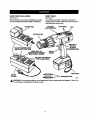
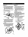
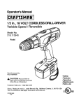
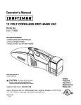
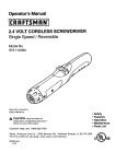
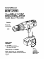
KNOWYOURDRILL-DRIVER
WRIST STRAP
See Figun51.
See Figure 1.
Beforeattempting to use any toolfaml/iarize yourself
with all operatingfeaturas and safety requirements.
A wdst strap is providedto reduce the chances of
droppingyour drill-driver,Place one hand throughthe
wdst stropwhen carryingtool,
BA'n'ERYPACK
TWO.SPEED
GEARTRAIN(HI-LO)
BITSTORAGE
LEVEL
DIRECTION
OF
ROTATION
SELECTOR
JGHTS
INDICATESOFTSTARTMODE
SWITCH
TNGGER
:I'iARGI NG MODE
BA'n'ERY
_
CHARGER
_
WRISTSTRAP
SCREWDRIVER
BITS
Fig. 1
_i_ WARN ING: If any parts are milming,do not operate tool untiJthe missingparts are replaced. Failureto do
so could result in possible sedous personal injury.
• Normally, the yellow and green lights on charger
will come on. This indicates charger is in soft start
mode end shouldswitch to fast charge mode within
5 minutes.When charger is in fast charge mode
the red lightwill come on. If after a period of 15
minutesthe yellow and green lights remain on,
remove battery pack, wait 1 minuteand reinsert
battery pack in charger. If the yellow and green
lightscontinueto remain on after an additional 15
minutes, the bettery pack is damaged and will not
accept a charge. Return battery packto your
nearest Seers Repair Center for checking or
replacing.
WARNING:Alwayswearsafetygoggles
or
safetyglasses
withsideshields
whenoperating
tools.Failureto dosocouldresultinobjects
beingthrownintoyoureyes, resulting in possible
sedous injury.
_lb WARNING: Do not allow familJadtywith your
drill-ddverto make you careless. Remember that
a careless fraction of a secondis sufficientto
inflictsevere injury.
CHARGING
BA'I-rERY PACK
The battery pack for this tool has been shippedin a
low charge conditionto prevent possible problems,
Therefore, you shouldcharge it until lighton front of
charger changes from red to green.
Note: Batteries will not reach full charge the first time
they are charged. Allow several cycles (ddlling
followed by recharging) for them to become fully
charged.
When your battery pack becomes fully charged, the
red lightwill turn OFF and the green light willturn
ON.
•
After normal usage, 1 hour of chargingtime is
required to be fullycharged, A minimumcharge
time of 1-1/2 hours is required to recharge a
completely dischargedtool.
• The battery pack will become slightlywarm to the
touchwhile charging.This is normal and does not
indicatea problem.
TO CHARGE
• Charge battery pack only with the charger
provided,
•
• Make sure power supply is normal household
voltage, 120 volts, 60 Ha, AC only.
Do not place charger in an area of extreme heat or
cold. It willwork best at normal roomtemperature.
• When bettedes become fully charged, unplug
chorger from power supply and remove the battery
pack.
• Connect charger to power supply.
•
Place battery pack in charger aligning raised db in
charger with groove in battery pack.
• Press down on battery pack to be sure contactson
battery pack engage propady with charger
contacts.
LED FUNCTION
•
OF CHARGER
LED WILL BE LIGHTED TO INDICATE STATUS OF CHARGER AND BA3"FERYPACK:
•
Red LED Lighted-- Fast Charging Mode.
•
Green LED Lighted= Slow Charging Mode and Fully Charged BatteP/Pack.
•
Yellow and Green LED Lighted= Soft Start Mode, orAfter 1/2 Hour Equals Hot or Defective
Battery Pack.
7
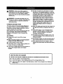
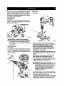
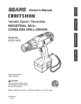
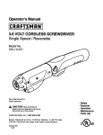
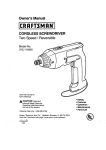
SWITCH
TO INSTALL
See Figure 2.
•
SWITCH
TRIGGER
VAR_BLE
SELECTOR
PACK
Lock switch tdgger on your drillby placingthe
directionof rotation selector in center position,
See Fkjum 5.
Place battery pack in your ddll, Align raised rib
inside ddll with groove on battery pack,
See Figure 4.
To turn your drill ON. depress the switchtdgger. To
turn it OFF, release the switch trigger.
cENTERPOSITION
(LOCK_
BATrERY
•
Fig. 2
SPEED
BAITERYPACK
Thistool hasa variable speed switch that delivershigher
speedand torquewithincreasedtdgger pressure.Speed
iscontrolledbythe amountof switchtriggerdepression.
LATCHES
Note: You might hear a whistling or dnging noise from
the switchduring use. Do not be concemed, this isa
normal part of the switch function,
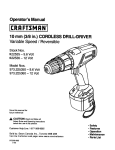
TWO-SPEED GEAR TRAIN
See Figure 3.
Your drill has a two-speed geer train designed for
ddningor driving at HI or LO speeds. A slide switch is
locatedon top of your ddll to select either HI or LO
speed. When using drill in the HI speed range, speed
will increase and unitwill have less power and torque.
When using drill in the LO speed range, speed will
decrease and unitwill have more power and torque.
Use HI speed for fast drillingor drivingapplications
and LO speed for high power and torque applications.
LOSPEED
TWOSPEED
GEARTRAIN(HI-LO)
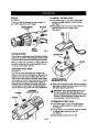
DEPRESSLATCHES
TO
RELEASE
BATTERYPACK
•
A
HI SPEED
Fig. 4
Make sure the latches on each side of your battery
pack snap into place and battery pack is secured in
drillbafom beginning operation.
CAUTION: When placing battery pack in your
drill, be sure raised db inside ddll alignswith
groove on battery pack and latches snap in place
properly.Improper assembly of battery pack can
cause damage to internalcomponents,
TO REMOVEBATrERYPACK
•
Lock switch trigger on your drill by placingthe
directionof rotationselector in center position,
See Figure 5.
• Locate latches on end of battery pack and depress
to release battery pack from your drill.
See Figure 4.
II Remove battery pack from your drill.
Fig, 3
SWITCHLOCK
See Figure 5.
The switchtriggercan be locked in the OFF position.
This feature can be used to prevent the possibilityof
accidental startingwhen not in use. To lock switch
trigger, place the directionof rotationselector in
center position,
CENTERPosmoN
(LOCK)
SELECTOR
REVERSE
1-7/I6 In,
BACKSIDE
OFCHARGER
SWITCH
TRIGGER
,_
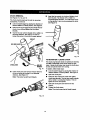
KEYLESS CHUCK
f
FORWARD
Fig. 6
See Figure 7.
Fig, 5
Yournew ddllhas a kaylesschuck.As the name implies,
you can handtightenor releaseddll bits inthe chuck
jaws, Grasp and holdthe collarof the chuckwithone
hand.Rotate the chuckbodywithyour otherhand. The
anows on the chuck indicatewhichdirectionto rctate
the chuck bodyin orderto LOCK (tighten)or UNLOCK
(release)the drillbit.
WARN IN G : Battery toolsare always in
operating condition. Therefore, switch should
always be lockedwhen not in use or carrying at
your side,
REVERSIBLE
See Figure 5.
UNLOCK
(RELEASE)
This tool has the featura of being reversible.The
directionof rotationis controlled by a selector located
above the switchtdgger. With the ddll held in normal
operating position,the directionof rotationselector
shouldhe positionedto the leftof the switch for
drilling.The ddllingdirection is reversed when the
selector'is to the dght of the switch,When the selector
is in center position,the switch trigger is locked,
_L CAUTION: To prevent gear damage, always
allow chuck to come to a complete stop before
changing the diroctionof rotationor the twospeed gear train (hi-lo).
CHUCK
BODY
DRILLBiT
LOCK
(TIGHTEN)
CHUCKCOLLAR
To stop, release switoh tdgger and allow the chuck to
come to a complete stop.
Fig. 7
WARNING: Do not hold chuck bodywith one
hand and use power of the ddll to tighten chuck
jaws on drill bits,Chuck bodycould slip in your
hand or your hand could slipand come in contact
with rotatingddll bit. This could cause an
accident resultingin sadous personal injurY.
CHARGER
See Figure 6.
Your charger has a "key hole" hanging feature for
convenient, space savingstorage. Screws shouldbe
installedso that center distancesare 1-7/16 inches
apa_.
9
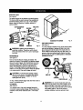
INSTALLINGBITS
REMOVING BITS
See F/guro 8.
See Figure 8.
•
Lock the switchtdgger by placingthe diroctionof
rotation selector in center position.See Figure 5.
•
•
Open or close chuck jaws to a pointwhere the
opening is slightlylarger than the bit size you
intend to use. Also, raise the front of your ddll
slightlyto keep the bit from falling out of the chuck
•
Loosenthe chuck jaws from drillbit.
•
To loosen: graspand hold the collar of the chuck
with one hand, while rotatingchuck body with your
other hand. Note; Rotate chuck body in the
directionofthe arrow marked UNLOCK to loosen
chuck jaws.
Do not use a wrench to tightenor loosenthe
chuckjaws.
jaws.
•
Insert drill bit straight into chuck the full length of
the jaws as shown in figure 8,
•
Tighten the chuck jaws on drill bit.
•
CHUCKBODY
D_U. BIT
•
Lock the switchtriggerby placingthe directionof
rotationselector in center position. See Figure 5.
Remove ddUbitfrom chuckjaws.
ADJUSTABLE
TORQUE CLUTCH
Your ddll is equipped with an adjustable torque clutch
for drivingdifferent types of screws intodifferent materials. The proper settingdepends on the type of matedal and the size of screw you am using.
TO ADJUST TORQUE
•
CHUCKJAWS
•
CHUCKCOLLAR
RIGHT
•
•
_k
Fig. 8
Identify the twenty four torque indicator settings
locatedon the front of your ddll. See F{gum 10.
Rotate adjustingring to the desired setting.
• 1-4
For driving small screws.
5- 8
To tighten the chuck jaws on ddll bit; grasp and
hold the collar of the chuck with one hand, while
rotatingthe chuck body with your other hand.
Note: Rotate the chuck body in the directionof
the arrow marked LOCK to tightenchuck jaws.
Do not use a wrench to tighten or loosenthe
chuck jaws.
For driving screws intosoft
material.
• 9 - f2
• 13 - 16
For driving screwsinto soft and hard
materials.
For drivingscrews in hard wood.
• 17 - 20
Fordrlving large screws.
• 21 - <k,_l For heavy drilling.
TO DECREASE
TORQUE
ADJUSTING
RING
WARNING: Make sure to insert ddll bit straight
intochuck jaws. Do not insert drillbit into chuck
jaws at an angle and then tighten, as shown in
figure 9. This could cause drill bit to be thrown
from drill resultingin possible sedouepersonal
injuryor damage to the chuck.
TO INCREASE
TORQUE
/
Fig. t 0
Fig. 9
10
Note:Remember
thetwo-speed
feature
(HI-LO) when
settingtorque. The amountof torque willvary dependingon which speed settingyou have your drill-driver.
Switchingto LO speed will increasetorque. Switching
to HI speed will decrease torque.
DRILLING
See Figure 13,
BIT STORAGE
See Figure 11.
When not in use, bits providedwith your drill can be
placed in the storagearea located on the top of your
drillas shown in figure 11.
STORAGE
AREA
_k
Fig, 11
WARNING: Always wear safety goggles or
safety glasses with side shields when operating
tools. Failure to do so could result in objects
being thrown intoyour eyes, resulting in possible
serious injury.
LEVEL DRILLING
See Figure 12.
A convenient new feature previded with your drill is a
level. It is recessed in the motor housingon top of
your drill. It can be used to keep drill bits level during
ddllingoperations,
Fig. 13
When drillinghard smooth surfaces use a center
punchto mark desired hole location.This will prevent
the ddll bit from slippingoffcenter as the hole is
started. However. the low speed feature allows
starting holeswithout canter punchingif desired, To
accomplishthis, simplyoperate yourddll at a low
speed untilthe hole is started.
The material to be drilled shouldbe secured in a vise
or with clamps to keep it from turning as the drill bit
rotates.
Hold tool firmlyand place the bit at the pointto be
drilled.Depress the switchtriggerto start tool.
Move the drillbit into the workplace applyingonly
enough pressure to keep the bit cutting,Do not force
or apply side pressure to elongate a hole.
WARNING: Be prepared for bindingor bit
breakthrough.When these situationsoccur, drill
has a tendency to grab and kickoppositeto the
directionof rotationand could cause loss of
control when breakingthrough material. If not
prepared, this loss of controlcan result in
possibleserious injury.
LL=/EL
When ddllingmetals, use a light o11on the drillbit to
keep itfrom overheating.The oil will prolongthe life of
the bit and increase the drillingaction.
If the bit jams in workpleca or if the drill stalls, release
switchtdgger immediately, Remove the bit from the
workpleca and determine the reason for jamming,
Fig. 12
11
CHUCKREMOVAL
Insert hex key wrench in chuck and tighten chuck
jaws securely. Tap sharplywith a mallet in a
counterclockwisedirection.This will loosen chuck
on the spindle. It can now be unscrewed by hand.
See Figure 16.
See Figures 14, 15, and 16.
The chuck must be removed in order to use some
accessodes. To remove:
•
Locktheswitchtdggerbyplacingthedirectlonof
rotationselector in center position.See Figure 5.
•
Inserta 5/16 inchor larger hexkey wrenchintothe
chuck ofyour ddlland tightenthe chuckjaws
securely.
•
Tap the hex kay wrench sharply with a mallet in a
clockwisedirection. See Figure 14. Thiswill
loosen the screw in the chuck for easy removal.
MALLET
KEYLESSCHUCI
Fig. 16
TO RETIGHTEN
A LOOSE CHUCK
The chuck may become loose on spindleand develop
a wobble. Periodicallycheck chuck screwfor tightness. A loose chuck screw may cause the chuckjaws
to bind and prevent them from closing,
CHUCKJAWS
WRENCH
Fig. 14
To tighten, follow these steps:
• Lock the switchtdgger by placingthe directionof
rotation selector in canter position. See Figure 5.
Open chuck jaws and remove wrench. Remove
the chuck screw by turning it in a clockwise
direction.See Figure 15.
Note: The screw has left hand threads.
•
•
i
Open the chuckjaws.
Insert hax key wrench into chuck and tighten
chuck jaws securely, Tap hax key wrench sharply
with a mallet in a clockwisedirection.This will
tighten chuck on the spindle.
Open the chuck jaws and remove hax key
wrench.
"lightenthe chuck screw.
Note: The chuck screw has left hand threads.
Fig. 15
12
_k
WARNING: When servicing, use only identical
Craftsman replacement parts. Use of any other
part may create a hazard or cause product
damage.
Avoid usingsolvents when cleaning plasticparts,
Most plasticsare susceptibleto damage from vadous
types of commercial solventsand may be damaged
by their use, Use clean clothsto remove dirt, dust, oil,
greasej
Do not abuse power tools, Abusive practicescan
damage tool as well as workplece,
Only the parts shownon parts list, page 15, are
intendedto be repaired or replaced by the customer.
All other parts shouldbe replaced at a Sears Service
Center.
,_
WARNING: Do not attemptto modifythis tool or
create accessoriesnot recommendedfor use
with this tool. Any such alteration or modification
is misuse and could result in a hazardous
conditionleadingto possible serious personal
injury.
•
Store and charge your batteries in a cool area.
Temperatures above normal room temperature
will shorten battery life.
Never store batteries in a discharged condition.
Recharge them immediatelyafter they are
discharged.
All batteries gradually lose their charge. The
higherthe temperature the quickerthey lose their
charge. If you store your tool for long pedods of
time withoutusing it, recharge the batteries every
monthor two. This practice will prolongbattery
life.
etc,
WARNING: Do not at any time let brake fluids,
gasoline, petroleum-basedproducts, penetrating
oils, etc. come in contact with plasticpelts. They
contain chemicalsthat can damage, weaken or
destroy plastic.
BATTERIES
Your drill'sbattery pack is equipped with 14 nickelcadmium rechargeable batteries. Length of service
from each charging will depend on the type of work
you are doing.
The batteries in this tool have been designed to
providemaximum trouble free life. However, like all
batteries, they will eventually wear out. Do not
disassemble battery pack and attempt to replace the
batteries. Handlingof these batteries, especially when
weadng rings and jewelry, could result in a serious
bum.
•
•
To obtain the longest possible battery life, we suggest
the following:
ACCESSORIES
FOR
THIS
AND
OTHER|
CRAFTSMAN
POWER ANDSE,.ECT,ON
BENCH TOOLS,|
[,OR
A :O,P,.E,E
O'1
v,srr,rOUR
NEAREST SEARS .ETA.
STORE.)
Ul_.'_B_e."
[|l_'ql--_
_,_//!
13
J DO NOT EXPOSE _1_
J_ TO RAINORUSEIN
DAMPLOC,T,ONS [J
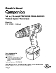
14
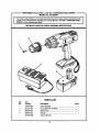
CRAFTSMAN
I
10 mm (3/8 In.), 16.8 VOLT CORDLESS
MODEL NO. 315.222560
DRILL-DRIVER
number in all correspondence regardingyour t0 mm (318 in.), 16.6 VOLT CORDLESS DRILLThe
modelnumber
willbe foundon
a plateattached tot hemotorhousing.Always mentionthe model
DRIVER
or when ordering
repair parts.
SEE BACK PAGE FOR PARTS ORDERING
1
INSTRUCTIONS
2
1
4
$
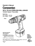
PARTS UST
Key
No.
Part
Number
Description
1
2
6t 6478-003
973015-001
Screw (Special) ................................................................. 1
Chuck (Item No..9-75188) ................................................. 1
3
4
982244-001
982245-001
Battery Pack ...................................................................... 1
972000-889
Quan.
Charger .............................................................................
Owner's Manual
1
d
15
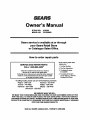
Owner's Manual
STOCK
MODEL
NO.
NO.
R 22256
315.222560
Sears service is available at or through
your Sears Retail Store
or Catalogue Sales Office.
How to order repair parts
SERVICE AND REPAIR PARTS
CALL 1-800-665-4455"
Keep this number handy shouldyou require a
selvice call or need to order repair parts.
If ordering parts, make sum you have the name, make and
model no. of the merchandise and the name and number
of the part you wish to order.
When ordedng repair parts
always give:
1. The Part Number
2. The Part Description
3. The Model Number
315.222560
4. The name of the item:
10 mm (3/6 in.), 16.8 Volt
Cordless Drill-Driver
*If calling locally, please use one of the following numbers:
Regina - 566-5124
Montreal - 333-5740
Toronto - 744-4900
HalIfax - 454-2444
Kitchener - 894-7590
Ottawa - 738-4440
Vancouver - 420-8211
WE MAKE
WITH THE
PROGRAM
PRODUCTS
WE SERVICE WHAT WE SELL.
THIS PLEDGE BECAUSE OUR CONCERN FOR OUR CUSTOMERS DOES NOT END
SALE. TO HONOR OUR PLEDGE, WE HAVE DEVELOPED A TOP-NOTCH SERVICE
STAFFED BY HIGHLY TRAINED SPECIALISTS. THEIR KNOWLEDGE OF OUR NEW
IS CONSTANTLY UPGRADED. THEY USE ONLY PARTS SPECIFICALLY DESIGNED
FOR YOUR FINE SEARS PRODUCTS.
Sold
by: SEARS
CANADA
INC., TORONTO
M5B 2B8