1
SUBISHI
C RIC
MOTION CONTROLLERS
MOTION
CONTROLLER
Q111BD-SSC
Q110BD-SSC
User's Manual
SAFETY PRECAUTIONS
(Read these precautions before using.)
When using this equipment, thoroughly read this manual and the associated manuals introduced in this
manual. Also pay careful attention to safety and handle the module properly.
These precautions apply only to this equipment. Refer to the Users manual of the QCPU module to use
for a description of the PLC system safety precautions.
These SAFETY PRECAUTIONS classify the safety precautions into two categories: "DANGER" and
"CAUTION".
DANGER
Indicates that incorrect handling may cause hazardous conditions,
resulting in death or severe injury.
! CAUTION
Indicates that incorrect handling may cause hazardous conditions,
resulting in medium or slight personal injury or physical damage.
!
Depending on circumstances, procedures indicated by ! CAUTION may also be linked to serious results.
In any case, it is important to follow the directions for usage.
Store this manual in a safe place so that you can take it out and read it whenever necessary. Always
forward it to the end user.
A-1
For Safe Operations
1. Prevention of electric shocks
!
DANGER
Never open the front case or terminal block covers of the servo amplifier while the power is ON
or the unit is running, as this may lead to electric shocks.
Never run the servo amplifier with the front case or terminal cover removed. The high voltage
terminal and charged sections will be exposed and may lead to electric shocks.
Never open the front case or terminal cover of the servo amplifier at times other than wiring
work or periodic inspections even if the power is OFF. The insides of the servo amplifier are
charged and may lead to electric shocks.
When performing wiring work or inspections, turn the power OFF, wait at least ten minutes, and
then check the voltage with a tester, etc.. Failing to do so may lead to electric shocks.
Be sure to ground the controller incorporating the Motion board, servo amplifier and servomotor.
(Ground resistance : 100 or less) Do not ground commonly with other devices.
The wiring work and inspections must be done by a qualified technician.
Wire the units after installing the Motion board, servo amplifier and servomotor. Failing to do
so may lead to electric shocks or damage.
Never operate the switches with wet hands, as this may lead to electric shocks.
Do not damage, apply excessive stress, place heavy things on or sandwich the cables, as this
may lead to electric shocks.
Do not touch the Motion board, servo amplifier or servomotor terminal blocks while the power is
ON, as this may lead to electric shocks.
Do not touch the built-in power supply, built-in grounding or signal wires of the Motion board
and servo amplifier, as this may lead to electric shocks.
For handling a personal computer, follow the instruction manual for the personal computer to be
used. Mistaken handling of a personal computer may lead to electric shocks or damage.
2. For fire prevention
!
CAUTION
Install the Motion board, servo amplifier, servomotor and regenerative resistor on Nonflammable
material. Direct installation on flammable material or near flammable material may lead to fire.
If a fault occurs in the Motion board or servo amplifier, shut the power OFF at the servo
amplifier’s power source. If a large current continues to flow, fire may occur.
When using a regenerative resistor, shut the power OFF with an error signal. The regenerative
resistor may abnormally overheat due to a fault in the regenerative transistor, etc., and may lead
to fire.
Always take heat measures such as flame proofing for the inside of the control panel where
the servo amplifier or regenerative resistor is installed and for the wires used. Failing to do so
may lead to fire.
A-2
3. For injury prevention
!
CAUTION
Do not apply a voltage other than that specified in the instruction manual on any terminal.
Doing so may lead to destruction or damage.
Do not mistake the terminal connections, as this may lead to destruction or damage.
Do not mistake the polarity ( + / - ), as this may lead to destruction or damage.
Do not touch the servo amplifier's heat radiating fins, regenerative resistor and servomotor, etc.,
while the power is ON and for a short time after the power is turned OFF. During this time, these
parts become very hot and may lead to burns.
Always turn the power OFF before touching the servomotor shaft or coupled machines, as
these parts may lead to injuries.
Do not go near the machine during test operations or during operations such as teaching.
Doing so may lead to injuries.
Do not touch the insides of the printed-circuit board or electronic parts of the Motion board.
Lead wires, etc. are exposed and may lead to injuries.
4. Various precautions
Strictly observe the following precautions.
Mistaken handling of the unit may lead to faults, injuries or electric shocks.
(1) System structure
!
CAUTION
Always install a leakage breaker on a controller incorporating the Motion board and servo
amplifier power source.
If installation of an electromagnetic contactor for power shut off during an error, etc., is specified
in the instruction manual for the servo amplifier, etc., always install the electromagnetic
contactor.
Install the emergency stop circuit externally so that the operation can be stopped immediately
and the power shut off.
Use the Motion board, servo amplifier, servomotor and regenerative resistor with the combinations
listed in the instruction manual. Other combinations may lead to fire or faults.
If safety standards (ex., robot safety rules, etc.,) apply to the system using the Motion board,
servo amplifier and servomotor, make sure that the safety standards are satisfied.
Construct a safety circuit externally of the Motion board or servo amplifier if the abnormal
operation of the Motion board or servo amplifier differ from the safety directive operation in
the system.
In systems where coasting of the servomotor will be a problem during the forced stop,
emergency stop, servo OFF or power supply OFF, use dynamic brakes.
A-3
!
CAUTION
Make sure that the system considers the coasting amount even when using dynamic brakes.
In systems where perpendicular shaft dropping may be a problem during the forced stop,
emergency stop, servo OFF or power supply OFF, use both dynamic brakes and
electromagnetic brakes.
The dynamic brakes must be used only on errors that cause the forced stop, emergency stop,
or servo OFF. These brakes must not be used for normal braking.
The brakes (electromagnetic brakes) assembled into the servomotor are for holding
applications, and must not be used for normal braking.
Install an external safety circuit to ensure the security of the entire system even during a fault of
the personal computer.
Configure the system with the system reliability ensured by fully understanding the performance
and functions (such as data saving at a power failure) of the personal computer.
The system must have a mechanical allowance so that the machine itself can stop even if the
stroke limits switch is passed through at the max. speed.
Use wires and cables that have a wire diameter, heat resistance and bending resistance
compatible with the system.
Use wires and cables within the length of the range described in the instruction manual.
The ratings and characteristics of the parts (other than Motion board, servo amplifier and
servomotor) used in a system must be compatible with the Motion board, servo amplifier and
servomotor.
Install a cover on the shaft so that the rotary parts of the servomotor are not touched during
operation.
There may be some cases where holding by the electromagnetic brakes is not possible due to
the life or mechanical structure (when the ball screw and servomotor are connected with a
timing belt, etc.). Install a stopping device to ensure safety on the machine side.
(2) Parameter settings and programming
!
CAUTION
Set the parameter values to those that are compatible with the Motion board, servo amplifier,
servomotor and regenerative resistor model and the system application. The protective
functions may not function if the settings are incorrect.
The regenerative resistor model and capacity parameters must be set to values that conform to
the operation mode, servo amplifier and servo power supply module. The protective functions
may not function if the settings are incorrect.
Set the mechanical brake output and dynamic brake output validity parameters to values that
are compatible with the system application. The protective functions may not function if the
settings are incorrect.
A-4
!
CAUTION
Set the stroke limit input validity parameter to a value that is compatible with the system
application. The protective functions may not function if the setting is incorrect.
Set the servomotor encoder type (increment, absolute position type, etc.) parameter to a value
that is compatible with the system application. The protective functions may not function if the
setting is incorrect.
Set the servomotor capacity and type (standard, low-inertia, flat, etc.) parameter to values that
are compatible with the system application. The protective functions may not function if the
settings are incorrect.
Set the servo amplifier capacity and type parameters to values that are compatible with the
system application. The protective functions may not function if the settings are incorrect.
Use the program commands for the program with the conditions specified in the instruction
manual.
Some devices used in the program have fixed applications, so use these with the conditions
specified in the instruction manual.
(3) Transportation and installation
!
CAUTION
Transport the product with the correct method according to the mass.
Use the servomotor suspension bolts only for the transportation of the servomotor. Do not
transport the servomotor with machine installed on it.
Do not stack products past the limit.
When transporting, installing or removing the Motion board, never touch the insides of the
printed-circuit board or electronic parts of the Motion controller. Instead, hold the front panel or
edges of the printed-circuit board.
When transporting servo amplifier, never hold the connected wires or cables.
When transporting the servomotor, never hold the cables, shaft or detector.
When transporting the servo amplifier, never hold the front case as it may fall off.
When transporting, installing or removing the servo amplifier, never hold the edges.
Install the unit according to the instruction manual in a place where the mass can be withstood.
Do not get on or place heavy objects on the product.
Always observe the installation direction.
For installation of the Motion board, use connecters and slots that conform with the specifications.
Keep the designated clearance between the Motion board and other boards.
Keep the designated clearance between the servo amplifier and control panel inner surface, and
the servo amplifier, and other devices.
A-5
!
CAUTION
Do not install or operate the Motion board, servo amplifiers or servomotors that are damaged
or that have missing parts.
Do not block the intake/outtake ports of the servomotor with cooling fan.
Do not allow conductive matter such as screw or cutting chips or combustible matter such as
oil to enter the Motion board, servo amplifier or servomotor.
The Motion board servo amplifier and servomotor are precision machines, so do not drop or
apply strong impacts on them.
Securely fix the Motion board and servo amplifier to the machine according to the instruction
manual. If the fixing is insufficient, these may come off during operation.
Always install the servomotor with reduction gears in the designated direction. Failing to do
so may lead to oil leaks.
Store and use the unit in the following environmental conditions.
Environment
Ambient
temperature
Ambient humidity
Storage
temperature
Atmosphere
Conditions
Motion board/Servo amplifier
According to each instruction manual.
According to each instruction manual.
According to each instruction manual.
Servomotor
0°C to +40°C (With no freezing)
(32°F to +104°F)
80% RH or less
(With no dew condensation)
-20°C to +65°C
(-4°F to +149°F)
Indoors (where not subject to direct sunlight).
No corrosive gases, flammable gases, oil mist or dust must exist
Altitude
1000m (3280.84ft.) or less above sea level
Vibration
According to each instruction manual
When coupling with the servomotor shaft end, do not apply impact such as by hitting with a
hammer. Doing so may lead to detector damage.
Do not apply a load larger than the tolerable load onto the servomotor shaft. Doing so may
lead to shaft breakage.
When not using the Motion board for a long time, disconnect the Motion board from the
personal computer. Also disconnect the power line from the servo amplifier
Place the Motion controller and servo amplifier in static electricity preventing vinyl bags and
store.
When storing for a long time, please contact with our sales representative.
A-6
(4) Wiring
CAUTION
!
Correctly and securely wire the wires. Reconfirm the connections for mistakes and the
terminal screws for tightness after wiring. Failing to do so may lead to run away of the
servomotor.
After wiring, install the protective covers such as the terminal covers to the original
positions.
Do not install a phase advancing capacitor, surge absorber or radio noise filter (option FRBIF) on the output side of the servo amplifier.
Correctly connect the output side (terminals U, V, W). Incorrect connections will lead the
servomotor to operate abnormally.
Do not connect a commercial power supply to the servomotor, as this may lead to trouble.
Do not mistake the direction of the surge absorbing
diode installed on the DC relay for the control signal
output of brake signals, etc. Incorrect installation may
lead to signals not being output when trouble occurs or
the protective functions not functioning.
Servo amplifier
VIN
(DC24V)
Control output
signal
RA
Do not connect or disconnect the connection cables between each unit, and the encoder
cable while the power is ON.
Securely tighten the cable connector fixing screws and fixing mechanisms. Insufficient
fixing may lead to the cables coming off during operation.
Do not bundle the power line or cables.
(5) Trial operation and adjustment
!
CAUTION
Confirm and adjust the program and each parameter before operation. Unpredictable
movements may occur depending on the machine.
Extreme adjustments and changes may lead to unstable operation, so never make them.
When using the absolute position system function, when starting up for the first time and when
the Motion board or absolute value motor has been replaced, always perform a home position
return.
A-7
(6) Usage methods
!
CAUTION
Immediately turn OFF the power if smoke, abnormal sounds or odors are emitted from the
Motion board, servo amplifier or servomotor.
Always execute a test operation before starting actual operations after the program or
parameters have been changed or after maintenance and inspection.
The units must be disassembled and repaired by a qualified technician.
Do not make any modifications to the unit.
Keep the effect or electromagnetic obstacles to a minimum by installing a noise filter or by using
wire shields, etc. Electromagnetic obstacles may affect the electronic devices used near the
Motion board or servo amplifier.
(7) Corrective actions for errors
!
CAUTION
If an error occurs in the self diagnosis of the Motion board or servo amplifier, confirm the
check details according to the instruction manual, and restore the operation.
If a dangerous state is predicted in case of a power failure or product failure, use a servomotor
with electromagnetic brakes or install a brake mechanism externally.
Use a double circuit construction so that the electromagnetic brake operation circuit can be
operated by emergency stop signals set externally.
Shut off with servo ON signal OFF,
alarm, magnetic brake signal.
Shut off with the
emergency stop
signal (EMG).
Servomotor
RA1
Electromagnetic
brakes
EMG
DC24V
If an error occurs, remove the cause, secure the safety and then resume operation after alarm
release.
The unit may suddenly resume operation after a power failure is restored, so do not go near
the machine. (Design the machine so that personal safety can be ensured even if the machine
restarts suddenly.)
A-8
(8) Maintenance, inspection and part replacement
!
CAUTION
Perform the daily and periodic inspections according to the instruction manual.
Perform maintenance and inspection after backing up the program and parameters for the
Motion board and servo amplifier.
Do not place fingers or hands in the clearance when opening or closing any opening.
Periodically replace consumable parts such as batteries according to the instruction manual.
Do not touch the lead sections such as ICs or the connector contacts.
Do not place the Motion board or servo amplifier on metal that may cause a power leakage or
wood, plastic or vinyl that may cause static electricity buildup.
Do not perform a megger test (insulation resistance measurement) during inspection.
When replacing the Motion board or servo amplifier, always set the new module settings
correctly.
When the Motion board or absolute value motor has been replaced, carry out a home
position return operation using one of the following methods, otherwise position displacement
could occur.
1) After writing the servo data to the Motion board using programming software, switch on
the power again, then perform a home position return operation.
2) Using the backup function of the programming software, load the data backed up before
replacement.
After maintenance and inspections are completed, confirm that the position detection of the
absolute position detector function is correct.
Do not short circuit, charge, overheat, incinerate or disassemble the batteries.
The electrolytic capacitor will generate gas during a fault, so do not place your face near the
Motion board or servo amplifier.
The electrolytic capacitor and fan will deteriorate. Periodically replace these to prevent
secondary damage from faults. Replacements can be made by our sales representative.
A-9
(9) About processing of waste
When you discard Motion controller, servo amplifier, a battery (primary battery)
and other option articles, please follow the law of each country (area).
!
CAUTION
This product is not designed or manufactured to be used in equipment or systems in situations
that can affect or endanger human life.
When considering this product for operation in special applications such as machinery or
systems used in passenger transportation, medical, aerospace, atomic power, electric power, or
submarine repeating applications, please contact your nearest Mitsubishi sales representative.
Although this product was manufactured under conditions of strict quality control, you are
strongly advised to install safety devices to forestall serious accidents when it is used in facilities
where a breakdown in the product is likely to cause a serious accident.
(10) General cautions
!
CAUTION
All drawings provided in the instruction manual show the state with the covers and safety
partitions removed to explain detailed sections. When operating the product, always return the
covers and partitions to the designated positions, and operate according to the instruction
manual.
A - 10
Revisions
*The manual number is given on the bottom left of the back cover.
Print Date
Jan., 2007
*Manual Number
IB(NA)-0300122-A First edition
Revision
Japanese Manual Number IB(NA)-0300121
This manual confers no industrial property rights or any rights of any other kind, nor does it confer any patent licenses.
Mitsubishi Electric Corporation cannot be held responsible for any problems involving industrial property rights which
may occur as a result of using the contents noted in this manual.
2006 MITSUBISHI ELECTRIC CORPORATION
A - 11
INTRODUCTION
Thank you for choosing the Motion board (Q111BD-SSC/Q110BD-SSC).
Please read this manual carefully so that equipment is used to its optimum.
CONTENTS
Safety Precautions ・・・・・・・・・・・・・・・・・・・・・・・・・・・・・・・・・・・・・・・・・・・・・・・・・・・・・・・・・・・・・・・・・・・・・・・A- 1
Revisions・・・・・・・・・・・・・・・・・・・・・・・・・・・・・・・・・・・・・・・・・・・・・・・・・・・・・・・・・・・・・・・・・・・・・・・・・・・・・・・ A-11
Contents ・・・・・・・・・・・・・・・・・・・・・・・・・・・・・・・・・・・・・・・・・・・・・・・・・・・・・・・・・・・・・・・・・・・・・・・・・・・・・・・ A-12
About Manuals ・・・・・・・・・・・・・・・・・・・・・・・・・・・・・・・・・・・・・・・・・・・・・・・・・・・・・・・・・・・・・・・・・・・・・・・・・・ A-15
1 OVERVIEW
1- 1 to 1- 3
1.1 Overview・・・・・・・・・・・・・・・・・・・・・・・・・・・・・・・・・・・・・・・・・・・・・・・・・・・・・・・・・・・・・・・・・・・・・・・・・・・・・ 1- 1
1.2 Model of Applicable OS ・・・・・・・・・・・・・・・・・・・・・・・・・・・・・・・・・・・・・・・・・・・・・・・・・・・・・・・・・・・・・・・・ 1- 2
1.3 Differences between Q111BD-SSC-Q110BD-SSC and Q173HCPU/Q172HCPU ・・・・・・・・・・・・・・・ 1- 2
2 SYSTEM CONFIGURATION
2- 1 to 2-18
2.1 Motion System Configuration ・・・・・・・・・・・・・・・・・・・・・・・・・・・・・・・・・・・・・・・・・・・・・・・・・・・・・・・・・・・ 2- 1
2.2.1 System overall configuration ・・・・・・・・・・・・・・・・・・・・・・・・・・・・・・・・・・・・・・・・・・・・・・・・・・・・・・・・ 2- 1
2.1.2 Function explanation of the Q111BD-SSC/Q110BD-SSC Motion board・・・・・・・・・・・・・・・・・・・・ 2- 3
2.1.3 Restrictions on Motion systems ・・・・・・・・・・・・・・・・・・・・・・・・・・・・・・・・・・・・・・・・・・・・・・・・・・・・・・ 2- 3
2.2 System Configuration Equipment ・・・・・・・・・・・・・・・・・・・・・・・・・・・・・・・・・・・・・・・・・・・・・・・・・・・・・・・・ 2- 4
2.3 General Specifications ・・・・・・・・・・・・・・・・・・・・・・・・・・・・・・・・・・・・・・・・・・・・・・・・・・・・・・・・・・・・・・・・・ 2- 7
2.4 Specifications of Equipment and Settings ・・・・・・・・・・・・・・・・・・・・・・・・・・・・・・・・・・・・・・・・・・・・・・・・・ 2- 8
2.4.1 Name of parts for Motion board ・・・・・・・・・・・・・・・・・・・・・・・・・・・・・・・・・・・・・・・・・・・・・・・・・・・・・・ 2- 8
2.4.2 SSCNET III cables and connection method・・・・・・・・・・・・・・・・・・・・・・・・・・・・・・・・・・・・・・・・・・・ 2- 14
3. DESIGN
3- 1 to 3- 8
3.1 System Designing Procedure ・・・・・・・・・・・・・・・・・・・・・・・・・・・・・・・・・・・・・・・・・・・・・・・・・・・・・・・・・・・ 3- 1
3.2 External Circuit Design ・・・・・・・・・・・・・・・・・・・・・・・・・・・・・・・・・・・・・・・・・・・・・・・・・・・・・・・・・・・・・・・・・ 3- 4
3.2.1 Power supply circuit design ・・・・・・・・・・・・・・・・・・・・・・・・・・・・・・・・・・・・・・・・・・・・・・・・・・・・・・・・・ 3- 6
3.2.2 Safety circuit design・・・・・・・・・・・・・・・・・・・・・・・・・・・・・・・・・・・・・・・・・・・・・・・・・・・・・・・・・・・・・・・・ 3- 7
3.3 Installation environment ・・・・・・・・・・・・・・・・・・・・・・・・・・・・・・・・・・・・・・・・・・・・・・・・・・・・・・・・・・・・・・・・ 3- 8
4. INSTALLATION AND WIRING
4- 1 to 4- 16
4.1 Procedure for installing Motion Board ・・・・・・・・・・・・・・・・・・・・・・・・・・・・・・・・・・・・・・・・・・・・・・・・・・・・ 4- 1
4.2 Installation and Uninstallation of Motion Board Utility ・・・・・・・・・・・・・・・・・・・・・・・・・・・・・・・・・・・・・・・ 4- 2
4.2.1 Installation and Uninstallation of Motion Board Utility・・・・・・・・・・・・・・・・・・・・・・・・・・・・・・・・・・・・ 4- 2
4.2.2 Uninstallation of Motion Board Utility ・・・・・・・・・・・・・・・・・・・・・・・・・・・・・・・・・・・・・・・・・・・・・・・・・ 4- 4
4.2.3 Instructions when the Motion board is installed without Motion Board Utility installed ・・・・・・・・ 4- 5
4.3 Motion board Installation ・・・・・・・・・・・・・・・・・・・・・・・・・・・・・・・・・・・・・・・・・・・・・・・・・・・・・・・・・・・・・・ 4- 12
4.3.1 Instructions for handling ・・・・・・・・・・・・・・・・・・・・・・・・・・・・・・・・・・・・・・・・・・・・・・・・・・・・・・・・・・・ 4- 12
4.3.2 Installation and removal of Motion board ・・・・・・・・・・・・・・・・・・・・・・・・・・・・・・・・・・・・・・・・・・・・・ 4- 12
4.4 Installation and Removal of Cable ・・・・・・・・・・・・・・・・・・・・・・・・・・・・・・・・・・・・・・・・・・・・・・・・・・・・・・ 4- 13
4.4.1 SSCNET III cable ・・・・・・・・・・・・・・・・・・・・・・・・・・・・・・・・・・・・・・・・・・・・・・・・・・・・・・・・・・・・・・・・・ 4- 13
A - 12
4.5 Wiring ・・・・・・・・・・・・・・・・・・・・・・・・・・・・・・・・・・・・・・・・・・・・・・・・・・・・・・・・・・・・・・・・・・・・・・・・・・・・・・ 4- 15
4.5.1 Instructions for wiring・・・・・・・・・・・・・・・・・・・・・・・・・・・・・・・・・・・・・・・・・・・・・・・・・・・・・・・・・・・・・・ 4- 15
4.5.2 Precautions of SSCNET III cable wiring ・・・・・・・・・・・・・・・・・・・・・・・・・・・・・・・・・・・・・・・・・・・・・・ 4- 16
5. TRIAL OPERATION AND ADJUSTMENT
5- 1 to 5- 4
5.1 Checklist before Trial Operation ・・・・・・・・・・・・・・・・・・・・・・・・・・・・・・・・・・・・・・・・・・・・・・・・・・・・・・・・・ 5- 1
5.2 Trial Operation and Adjustment Procedure ・・・・・・・・・・・・・・・・・・・・・・・・・・・・・・・・・・・・・・・・・・・・・・・・ 5- 2
5.3 Operating System Software Installation Procedure ・・・・・・・・・・・・・・・・・・・・・・・・・・・・・・・・・・・・・・・・・ 5- 4
6. MOTION BOARD UTILITY OPERATION
6- 1 to 6- 6
6.1 Start and Exit of Motion Board Utility ・・・・・・・・・・・・・・・・・・・・・・・・・・・・・・・・・・・・・・・・・・・・・・・・・・・・・ 6- 2
6.1.1 Start of Motion Board Utility ・・・・・・・・・・・・・・・・・・・・・・・・・・・・・・・・・・・・・・・・・・・・・・・・・・・・・・・・・ 6- 2
6.1.2 Exit of Motion Board Utility ・・・・・・・・・・・・・・・・・・・・・・・・・・・・・・・・・・・・・・・・・・・・・・・・・・・・・・・・・・ 6- 2
6.2 Operation of Motion Board Utility ・・・・・・・・・・・・・・・・・・・・・・・・・・・・・・・・・・・・・・・・・・・・・・・・・・・・・・・・ 6- 3
7. POSITIONING DEDICATED SIGNALS
7- 1 to 7-24
7.1 Internal Relays ・・・・・・・・・・・・・・・・・・・・・・・・・・・・・・・・・・・・・・・・・・・・・・・・・・・・・・・・・・・・・・・・・・・・・・・・ 7- 1
7.1.1 Axis status・・・・・・・・・・・・・・・・・・・・・・・・・・・・・・・・・・・・・・・・・・・・・・・・・・・・・・・・・・・・・・・・・・・・・・・・ 7-.3
7.1.2 Axis command signal・・・・・・・・・・・・・・・・・・・・・・・・・・・・・・・・・・・・・・・・・・・・・・・・・・・・・・・・・・・・・・・ 7- 4
7.1.3 Virtual servomotor axis status ・・・・・・・・・・・・・・・・・・・・・・・・・・・・・・・・・・・・・・・・・・・・・・・・・・・・・・・ 7- 5
7.1.4 Virtual servomotor axis command signal ・・・・・・・・・・・・・・・・・・・・・・・・・・・・・・・・・・・・・・・・・・・・・・ 7- 6
7.1.5 Cam axis command signal ・・・・・・・・・・・・・・・・・・・・・・・・・・・・・・・・・・・・・・・・・・・・・・・・・・・・・・・・・・ 7- 7
7.1.6 Smoothing clutch complete signal ・・・・・・・・・・・・・・・・・・・・・・・・・・・・・・・・・・・・・・・・・・・・・・・・・・・・ 7- 8
7.1.7 Common device ・・・・・・・・・・・・・・・・・・・・・・・・・・・・・・・・・・・・・・・・・・・・・・・・・・・・・・・・・・・・・・・・・・・ 7- 9
7.2 Data Registers ・・・・・・・・・・・・・・・・・・・・・・・・・・・・・・・・・・・・・・・・・・・・・・・・・・・・・・・・・・・・・・・・・・・・・・・ 7-12
7.2.1 Axis monitor device ・・・・・・・・・・・・・・・・・・・・・・・・・・・・・・・・・・・・・・・・・・・・・・・・・・・・・・・・・・・・・・・ 7-13
7.2.2 Control change register・・・・・・・・・・・・・・・・・・・・・・・・・・・・・・・・・・・・・・・・・・・・・・・・・・・・・・・・・・・・ 7-14
7.2.3 Virtual servomotor axis monitor device・・・・・・・・・・・・・・・・・・・・・・・・・・・・・・・・・・・・・・・・・・・・・・・ 7-15
7.2.4 Cam axis monitor device・・・・・・・・・・・・・・・・・・・・・・・・・・・・・・・・・・・・・・・・・・・・・・・・・・・・・・・・・・・ 7-16
7.3 Motion Registers (#) ・・・・・・・・・・・・・・・・・・・・・・・・・・・・・・・・・・・・・・・・・・・・・・・・・・・・・・・・・・・・・・・・・・ 7-17
7.4 Special Relays / Special Registers ・・・・・・・・・・・・・・・・・・・・・・・・・・・・・・・・・・・・・・・・・・・・・・・・・・・・・・ 7-18
7.4.1 Special Relays(SP.M) ・・・・・・・・・・・・・・・・・・・・・・・・・・・・・・・・・・・・・・・・・・・・・・・・・・・・・・・・・・・・・ 7-18
7.4.2 Special Registers (SP.D) ・・・・・・・・・・・・・・・・・・・・・・・・・・・・・・・・・・・・・・・・・・・・・・・・・・・・・・・・・・ 7-20
8. AUTO RUN FUNCTION
8- 1 to 8-16
8.1 Outline of auto run function ・・・・・・・・・・・・・・・・・・・・・・・・・・・・・・・・・・・・・・・・・・・・・・・・・・・・・・・・・・・・・ 8- 1
8.1.1 How to set the auto run function ・・・・・・・・・・・・・・・・・・・・・・・・・・・・・・・・・・・・・・・・・・・・・・・・・・・・・ 8- 1
8.2 PC monitoring function ・・・・・・・・・・・・・・・・・・・・・・・・・・・・・・・・・・・・・・・・・・・・・・・・・・・・・・・・・・・・・・・・・ 8- 2
8.2.1 Outline of PC monitoring function ・・・・・・・・・・・・・・・・・・・・・・・・・・・・・・・・・・・・・・・・・・・・・・・・・・・・ 8- 2
8.3 Outline of WDT relay output function ・・・・・・・・・・・・・・・・・・・・・・・・・・・・・・・・・・・・・・・・・・・・・・・・・・・・・ 8- 4
8.4 Compatibility with user application ・・・・・・・・・・・・・・・・・・・・・・・・・・・・・・・・・・・・・・・・・・・・・・・・・・・・・・・ 8- 4
8.5 Data Batch Transfer Function between Personal Computer and Motion Board ・・・・・・・・・・・・・・・・・ 8- 5
8.5.1 Data Batch Transfer with Automatic Refresh in Operation Cycle and Main Cycle ・・・・・・・・・・・ 8- 6
8.5.2 Data batch transfer with Motion SFC program (BMOV instruction) ・・・・・・・・・・・・・・・・・・・・・・・ 8-14
8.5.3 Data Batch Transfer between Personal Computer and PCI2-Port Memory ・・・・・・・・・・・・・・・・ 8-16
A - 13
9 INSPECTION AND MAINTENANCE
9- 1 to 9-12
9.1 Battery・・・・・・・・・・・・・・・・・・・・・・・・・・・・・・・・・・・・・・・・・・・・・・・・・・・・・・・・・・・・・・・・・・・・・・・・・・・・・・・ 9- 1
9.1.1 Battery service life time ・・・・・・・・・・・・・・・・・・・・・・・・・・・・・・・・・・・・・・・・・・・・・・・・・・・・・・・・・・・・・ 9- 1
9.1.2 Battery replacement procedure ・・・・・・・・・・・・・・・・・・・・・・・・・・・・・・・・・・・・・・・・・・・・・・・・・・・・・・ 9- 2
9.2 Troubleshooting ・・・・・・・・・・・・・・・・・・・・・・・・・・・・・・・・・・・・・・・・・・・・・・・・・・・・・・・・・・・・・・・・・・・・・・・ 9- 3
9.2.1 Basics of troubleshooting ・・・・・・・・・・・・・・・・・・・・・・・・・・・・・・・・・・・・・・・・・・・・・・・・・・・・・・・・・・・ 9- 3
9.2.2 Troubleshooting of Motion board ・・・・・・・・・・・・・・・・・・・・・・・・・・・・・・・・・・・・・・・・・・・・・・・・・・・・・ 9- 4
9.3 Confirm method of Error Code ・・・・・・・・・・・・・・・・・・・・・・・・・・・・・・・・・・・・・・・・・・・・・・・・・・・・・・・・・ 9-11
APPENDICES
App- 1 to App- 5
APPENDIX 1 Cables ・・・・・・・・・・・・・・・・・・・・・・・・・・・・・・・・・・・・・・・・・・・・・・・・・・・・・・・・・・・・・・・・・・・
APPENDIX 1.1 SSCNET cables ・・・・・・・・・・・・・・・・・・・・・・・・・・・・・・・・・・・・・・・・・・・・・・・・・・・・・・・
APPENDIX 2 Exterior Dimensions ・・・・・・・・・・・・・・・・・・・・・・・・・・・・・・・・・・・・・・・・・・・・・・・・・・・・・・・
APPENDIX 2.1 Motion board ・・・・・・・・・・・・・・・・・・・・・・・・・・・・・・・・・・・・・・・・・・・・・・・・・・・・・・・・・・
APPENDIX 2.2 Connector ・・・・・・・・・・・・・・・・・・・・・・・・・・・・・・・・・・・・・・・・・・・・・・・・・・・・・・・・・・・・
A - 14
App- 1
App- 1
App- 4
App- 4
App- 5
About Manuals
The following manuals are related to this product.
When requesting additional manuals, please refer to this list.
Related Manuals
(1) Motion controller
Manual Number
Manual Name
(Model Code)
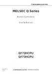
Q173HCPU/Q172HCPU Motion controller Programming Manual (COMMON)
This manual explains the Multiple CPU system configuration, performance specifications, common
IB-0300111
(1XB911)
parameters, auxiliary/applied functions and others.
(Optional)
Q173HCPU/Q172HCPU Motion controller (SV13/SV22) Programming Manual (Motion SFC)
This manual explains the functions, programming, debugging, error codes and others of the Motion SFC.
(Optional)
Q173HCPU/Q172HCPU Motion controller (SV13/SV22) Programming Manual (REAL MODE)
This manual explains the servo parameters, positioning instructions, device list, error list and others.
(Optional)
IB-0300112
(1XB912)
IB-0300113
(1XB913)
Q173HCPU/Q172HCPU Motion controller (SV22) Programming Manual (VIRTUAL MODE)
This manual describes the dedicated instructions use to the synchronous control by virtual main shaft,
mechanical system program create mechanical module.
This manual explains the servo parameters, positioning instructions, device list, error list and others.
IB-0300114
(1XB914)
(Optional)
(2) Servo amplifier
Manual Number
Manual Name
(Model Code)
MR-J3-□B Servo Amplifier Instruction Manual
This manual explains I/O signals, part names, parameters, installation procedure, etc. of
the servo amplifier MR-J3-□B.
SH-030050
(1CW201)
(Optional)
Fully Closed Loop MR-J3-□B-RJ006 Servo Amplifier Instruction Manual
This manual provides explanations for products that take position feedback signals, which
are transmitted from load side encoders such as linear encoders, into servo amplifiers, in
order to perform fully closed loop control.
(Optional)
A - 15
SH-030056
(1CW304)
MEMO
A - 16
1 OVERVIEW
1. OVERVIEW
1.1 Overview
1
This manual describes changes to SV13/SV22 that were incorporated with the
release of the SSCNET based PCI I/F Motion Board (Q111BD-SSC/Q110BDSSC).
Changes from earlier released SSCNETIII based Motion CPU modules
(Q173HCPU/Q172HCPU) are described in principle.
In this manual, the following abbreviations are used.
Generic term/Abbreviation
Q111BD-SSC/Q110BD-SSC or Motion board
Q173HCPU/Q172HCPU or Motion CPU
(module)
Description
Q111BD-SSC/Q110BD-SSC Motion board
Q173HCPU/Q172HCPU/Q173HCPU-T/Q172HCPU-T Motion CPU module
MR-J3-[ ]B
Servo amplifier model MR-J3-[ ]B
AMP or Servo amplifier
General name for "servo amplifier model MR-J3-[ ]B"
Programming software package
General name for "MT Developer" and "GX Developer"
Operating system software
General name for "SW[ ]RN-SV[ ]Q[ ]"
Operating system software for conveyor assembly use (Motion SFC) :
SV13
SW6RN-SV13Q[ ]
Operating system software for automatic machinery use (Motion SFC) :
SV22
SW6RN-SV22Q[ ]
SSCNET III (Note-1)
High speed synchronous network between Motion controller and servo amplifier
High speed synchronous communication network between Motion controller and servo
SSCNET (Note-1)
amplifier
PCI2 port memory orPCI2 port
2-port memory between a personal computer and the motion board
(Note-1): SSCNET: Servo System Controller NETwork
REMARK
This User’s Manual describes only the changes from the conventional
SSCNET III compatible Motion CPU modules (Q173HCPU/Q172HCPU).
Therefore, refer to the following manuals relevant to each module for
information about the design methods for programs and parameters which
are not described.
Item
Reference Manual
Operation method for MT Developer
SV13/SV22
SV13/SV22
Related documentation for programming support.
• Auxiliary and applied functions (common)
Q173HCPU/Q172HCPU Motion controller
• Design method for Motion SFC program
Q173HCPU/Q172HCPU Motion controller (SV13/SV22)
• Design method for Motion SFC parameter
Programming Manual (Motion SFC)
Programming Manual (COMMON)
• Design method for positioning control program in the
real mode
SV22
(Virtual mode)
Q173HCPU/Q172HCPU Motion controller (SV13/SV22)
• Design method for positioning control parameter
Programming Manual (REAL MODE)
• Design method for mechanical system program
Q173HCPU/Q172HCPU Motion controller (SV22)
1-1
Programming Manual (VIRTUAL MODE)
1 OVERVIEW
1.2 Model of Applicable OS
Board Type
OS Type
Model of OS
Q111BD-SSC
SV13
SW6RN-SV13QV
(Number of control axes: 32 axes)
SV22
SW6RN-SV22QU
Q110BD-SSC
SV13
SW6RN-SV13QT
(Number of control axes: 16 axes
SV22
SW6RN-SV22QS
1.3 Differences between Q111BD-SSC-Q110BD-SSC and Q173HCPU/Q172HCPU
Differences between Q111BD-SSC-Q110BD-SSC and Q173HCPU/Q172HCPU
concerning SV13/SV22 are shown below.
(1) Motion control function (Real mode)
Item
Q111-BD-SSC
Number of control axes
Q110-BD-SSC
32 axes
16 axes
0.44ms/ 1 to 3 axes
SV13
0.44ms/ 1 to 3 axes
0.88ms/ 4 to 10 axes
1.77ms/11 to 20 axes
3.55ms/21 to 32 axes
Operation cycle
(default)
0.88ms/ 4 to 10 axes
1.77ms/11 to 16 axes
0.88ms/ 1 to 5 axes
SV22
0.88ms/ 1 to 5 axes
1.77ms/6 to 14 axes
3.55ms/15 to 28 axes
7.11ms/29 to 32 axes
1.77ms/6 to 14 axes
3.55ms/15 to 16 axes
PTP(Point to Point) control, Speed control, Fixedpitch feed, Constant speed control, Position followControl modes
up control, Speed control with fixed position stop,
Speed switching control, High-speed oscillation
control, Synchronous control (SV22)
Home position return
function
Teaching operation function
0.88ms/ 4 to 8 axes
3.55ms/21 to 32 axes
0.88ms/ 1 to 5 axes
1.77ms/6 to 14 axes
0.88ms/ 1 to 5 axes
3.55ms/15 to 28 axes
1.77ms/6 to 8 axes
7.11ms/29 to 32 axes
PTP(Point to Point) control, Speed control, Speedposition control, Fixed-pitch feed, Constant speed
control, Position follow-up control, Speed control
with fixed position stop, Speed switching control,
High-speed oscillation control, Synchronous control
(SV22)
Data set type (2 types), Dog cradle type, Stopper
Limit switch combined type (Home position return
type (2 types), Limit switch combined type (Home
re-try function provided, home position shift
position return re-try function provided, home
function provided)
position shift function provided)
None
3 units can be connected.
None
operation function
Peripheral unit I/F
0.44ms/ 1 to 3 axes
1.77ms/11 to 20 axes
Proximity dog type (2 types), Count type (3 types),
Synchronous encoder
High speed reading function
0.44ms/ 1 to 3 axes
0.88ms/ 4 to 10 axes
types), Dog cradle type, Stopper type (2 types),
operation function
External input signal
Q172HCPU
8 axes
Proximity dog type (2 types), Data set type (2
Manual pulse generator
Number of SSCNET III I/F
Q173HCPU
32 axes
2ch
12 units can be
8 units can be
connected.
connected.
2ch
1ch
1ch
General purpose input signal of servo amplifier
Q172LX or general purpose input signal of servo
FLS, RLS and DOG are used.
amplifier
Pulse generator and synchronous encoder I/F unit,
None
programmable logic controller input unit
PCI bus
USB/SSCNET
None
Provided(Q173HCPU-T/Q172HCPU-T : SV13)
1-2
1 OVERVIEW
(2) Motion control function (Virtual mode)
Item
Drive
Mechanical
Q111BD-SSC
Synchronous encoder
modules
Transmission
modules
Clutch
Q110BD-SSC
Unusable
External input
Q173HCPU
Q172HCPU
12 axes
8 axes
Unusable
mode
Usable
(3) Motion SFC function
Item
Motion SFC
execute
specification
(Executed
task)
Event task
(Execution
can be
masked.)
External interrupt
MULTR
Q110BD-SSC
None
PLC interrupt
None
NMI task
MULTW
None
Write device data to
shared CPU memory
Read device data from
shared CPU memory
Q173HCPU
Q172HCPU
Execute when input ON is set among
interrupt module QI60 (16 points).
Execute with interrupt instruction
(GINT) from PLC CPU.
Execute when input ON is set among
interrupt module QI60 (16 points).
None
Provided
None
Provided
None
Provided
None
Provided
Write device data to
Motion SFC
program
Q111BD-SSC
TO
instruction
intelligent function
module/special function
module.
Read device data from
FROM
intelligent function
module/special function
module.
1-3
1 OVERVIEW
MEMO
1-4
2 SYSTEM CONFIGURATION
2. SYSTEM CONFIGURATION
This section describes the Q111BD-SSC/Q110BD-SSC system configuration,
precautions on use of system and configured equipments.
2.1 Motion System Configuration
2
2.1.1 System overall configuration
Operating system software
SW6RN-SV13QV
For Q111BD-SSC
SW6RN-SV22QU
SW6RN-SV13QT
For Q111BD-SSC
SW6RN-SV22QS
Motion board (Q111BD-SSC/Q110BD-SSC)
Maximum number of installed boards: 4 (total 128 axes (32 axes 4)
Q111BD-SSC and Q110BD-SSC can be connected simultaneously.
Use the board ID setting switch of the Motion Board to designate the
board ID. (Refer to Section 3.2)
PCI bus
SSCNET III (CH1)
d1
M
E
d2
M
E
d15
d16
M
E
M
E
d15
d16
M
E
M
E
Servo external signal (FLS, RLS, DOG)
Personal computer
(IBM PC/AT)
(Win2000/WinXP)
MR-J3-[ ]B model Servo amplifier
(Up to 16 axes/system)
SSCNET III (CH2)
d1
M
E
d2
M
E
Servo external signal (FLS, RLS, DOG)
MR-J3-[ ]B model Servo amplifier
(Up to 16 axes/system)
*: Q111BD-SSC use only
CAUTION
• Construct a safety circuit externally of the Motion controller or servo amplifier if the abnormal
operation of the Motion board or servo amplifier differ from the safety directive operation in the
system.
• The ratings and characteristics of the parts (other than Motion board, servo amplifier and servomotor)
used in a system must be compatible with the Motion board, servo amplifier and servomotor.
• Set the parameter values to those that are compatible with the Motion board, servo amplifier,
servomotor and regenerative resistor model and the system application. The protective functions may
not function if the settings are incorrect.
2-1
2 SYSTEM CONFIGURATION
POINT
(1) This system does not operate in the standby mode and suspend mode
provided for Windows.
Select None for the standby mode and suspend mode.
(2) Power-on and shutdown of servo amplifier
1) Keep the control power of all the servo amplifiers connected to the
Motion board turned on during operation. Otherwise servo amplifiers
connected to servo amplifiers later than the one turned off do not
communicate with the Motion board.
(Note): Even if there is a servo amplifier that is not registered to the
system (not used) in the middle, keep the control power of the
servo amplifier turned on. If it is turned off, communication is
not made with the servo amplifiers connected later than the one
that is turned off.
2) If the control power of the servo amplifier is turned off during operation,
Motion CPU stops communicating with the servo amplifiers later than
the one that is turned off, and those servo amplifiers are in the servooff state.
(Note): The servo amplifiers connected earlier than the one that is
turned off keep operating without any effects.
3) If the control power of the shutoff servo amplifier is turned on again
after the event specified in above item 1, Motion board restarts
communicating with the servo amplifiers that have been disconnected.
4) There is no limitation in the power-on sequence of the Motion board
and servo amplifiers.
(3) Rotary switch setting of servo amplifier
1) There is no need to arrange servo amplifiers in the order of the rotary
switch setting of the servo amplifier.
2) Specify so that axis d1 of the Motion board system setting is "0," axis
d2 "1," and axis d16 "F".
(4) External signal input
1) The upper limit switch, lower limit switch and near-point dog signal of
each axis can be entered, using the general purpose inputs of each
servo amplifier.
2-2
2 SYSTEM CONFIGURATION
2.1.2 Function explanation of the Q111BD-SSC/Q110BD-SSC Motion board
(1) Up to 32 axes servo amplifiers per 2 systems (up to 16 axes per 1 system) can
be used in Q111BD-SSC. Up to 16 axes servo amplifiers per 1 system can be
used in Q110BD-SSC.
(2) It is possible to set the program which synchronized with the motion operation
cycle and executed at fixed cycle (0.88[ms], 1.77[ms], 3.55[ms], 7.11[ms],
14.2[ms]).
(3) It is possible to execute a download of servo parameters to servo amplifier,
servo ON/OFF to servo amplifier and position commands, etc. by connecting
between the Q111BD-SSC/Q110BD-SSC and servo amplifier with SSCNET III
cable.
(4) It is possible to select the servo control functions/programming languages by
installing the corresponding operating system software in the Q111BD-SSC/
Q110BD-SSC.
(5) Motion board becomes difficult to be influenced of an electromagnetic noise
from servo amplifier, etc. by using the SSCNET III cable (optical
communication).
2.1.3 Restrictions on Motion systems
(1) When the operation cycle is 0.4[ms], set the system setting as the axis select
switch of servo amplifier "0 to 7".
If the axis select switch of servo amplifier "8 to F" is set, the servo amplifiers are
not recognized.
2-3
2 SYSTEM CONFIGURATION
2.2 System Configuration Equipment
(1) Table of Motion board related module
Part name
Model Name
Q111BD-SSC
Motion board
Q110BD-SSC
Battery
Q6BAT
MR-J3BUS∆M
(Note-1)
SSCNET III
cable
MR-J3BUS∆M-A
(Note-1)
MR-J3BUS∆M-B
(Note-2)
(Note-1)
Description
Up to 32 axes control, Operation cycle 0.4[ms] or more
Up to 16 axes control, Operation cycle 0.4[ms] or more
For IC-RAM memory backup of Q111BD-SSC/Q110BD-SSC
(Motion SFC programs, Servo programs, Parameters)
• Q111BD-SSC/Q110BD-SSC ↔ MR-J3-[ ]B
• MR-J3-[ ]B ↔ MR-J3-[ ]B
• Standard code for inside panel
• 0.15m (0.49ft.), 0.3m (0.98ft.), 0.5m (1.64ft.), 1m (3,28ft.), 3m(9.84ft.)
• Q111BD-SSC/Q110BD-SSC ↔ MR-J3-[ ]B
• MR-J3-[ ]B ↔ MR-J3-[ ]B
• Standard cable for outside panel
• 5m (16.40ft.), 10m (32.81ft.), 20m(65.62ft.)
• Q111BD-SSC/Q110BD-SSC ↔ MR-J3-[ ]B
• MR-J3-[ ]B ↔ MR-J3-[ ]B
• Long distance cable
• 30m (98.43ft.), 40m (131.23ft.), 50m (164.04ft.)
(Note-1): ∆=Cable length (015: 0.15m (0.49ft.), 03: 0.3m (0.98ft.), 05: 0.5m (1.64ft.), 1: 1m (3.28ft.),
2: 2m (6.56ft.), 3: 3m (9.84ft.), 5: 5m (16.40ft.), 10: 10m (32.81ft.), 20: 20m (65.62ft.),
30: 30m (98.43ft.), 40: 40m (131.23ft.), 50:50m (164.04ft.)
(Note-2): Please contact your nearest Mitsubishi sales representative for the cable of less than
30m(98.43ft.).
(2) Table of servo amplifier
Part name
MR-J3 series
servo amplifier
Battery
Model Name
□B
Description
MR-J3-
Refer to the catalog of the servo amplifier.
MR-J3BAT
Back-up for the absolute position detection
(3) Software packages
(a) Operating system software packages
Application
Software Package
Q111BD-SSC
Q110BD-SSC
For conveyor assembly SV13 (Motion SFC)
SW6RN-SV13QV
SW6RN-SV13QT
For automatic machinery SV22 (Motion SFC)
SW6RN-SV22QU
SW6RN-SV22QS
(b) Integrated start-up support software package
Application
SW6RNC-
Software Package
• Conveyor assembly software
: SW6RN-GSV13P-E0011
• Automatic machinery software
: SW6RN-GSV22P-E0011
SW6RNC-GSVE-E0011
• Cam data creation software
: SW3RN-CAMP
(Integrated start-up
• Digital oscilloscope software
: SW6RN-DOSCP-E0011
support software
• Communication system software : SW6RN-SNETP-E0011
(1 CD-ROM) )
• Document print software
: SW3RN-DOCPRNP
SW20RN-DOCPRNP
GSVPROE-E0011
• Motion Board Utility
SW6RNC-GSVHELPE-E0011
(Operation manual
• Operation manual : SW6RNC-GSVHELP-E0011
(1 CD-ROM) )
Installation manual
(Note): Operating environment of the programming software is Windows 2000/Windows XP
Japanese version) only.
2-4
2 SYSTEM CONFIGURATION
(4) Operating environment of personal computer
(a)Operating environment of the Motion board
The operating environment of the Motion board is shown below.
Description
Item
Q111BD-SSC
Q110BD-SSC
Bus type
PCI
Address bit
32bit
Data bit
32bit
System clock
33MHz
System voltage
+5V
106.7 (4.20) × 174.6 (6.87)
Measure [mm(inch)]
Hot swap
Not compatible
Base address
Set the configuration register using BIOS.
Current consumption
1.01
(5VDC) [A]
0.77
(b)System requirements of integrated start-up support software package
The system requirements of integrated start-up support software package is
shown in the following.
IBM PC/AT with which Windows 2000/Windows XP English version
operates normally.
Windows 2000
Item
CPU
Windows XP
Pentium II 233MHz or more
Pentium II 450MHz or more
Memory capacity
Recommended 64MB or more
Recommended 192MB or more
Hard disk free space
* Refer to the following table in Section 1) SW6RN-GSVPROE-E0011.
Disk drive
3.5inch (1.44MB) floppy disk drive, CD-ROM disk drive
Display
800×600 pixels, 256 colors or more
(Note-1) : Windows are either registered trademarks or trademarks of Microsoft Corporation in the United
States and/or other countries.
(Note-2) : Pentium are trademarks or registered trademarks of Intel Corporation or its subsidiaries in the
United States and other countries.
It is necessary the following capacity depending on the installed software.
1) SW6RN-GSVPROE-E0011
Size
Model Name
SW6RNC-GSVE-E0011
40MB
40MB
2MB
10MB
Standard
4MB
Custom
5MB
(When all selection)
34MB
33MB
SW6RN-GSV13P-E0011
SW6RN-GSV22P-E0011
SW3RN-CAMP
SW6RN-DOSCP-E0011
SW6RN-SNETP-E0011
SW3RN-DOCPRNP
SW20RN-DOCPRNP
SW6RNC-GSVHELPE-E0011
23MB
25MB
3MB
5MB
3MB
4MB
4MB
2) Motion board Utility
Model Name
Motion board Utility
Size
1MB
2-5
2 SYSTEM CONFIGURATION
(5) Related software packages
(b) Servo set up software package
Model Name
MR Configurator
Software Package
MRZJW3-SETUP221
Version
B1 or later
POINT
(1) When the operation of Windows is not unclear in the operation of this
software, refer to the manual of Windows or guide-book from the other
supplier.
(2) The screen might not be correctly displayed depending on the system font
size of Windows 2000/ Windows XP.
Be sure to use the small size fonts.
(3) Although SW6RNC-GSVE and SW6RNC-GSVE-E0011 can be installed
on the same personal computer, they cannot be started simultaneously.
2-6
2 SYSTEM CONFIGURATION
2.3 General Specifications
General specifications of Q111BD-SSC/Q110BD-SSC module are shown below.
Item
Specification
Operating ambient temperature
0 to 55°C (32 to 131°F)
Storage ambient temperature
-20 to 65°C (-13 to 149°F)
Operating ambient humidity
10 to 90% RH, non-condensing
Storage ambient humidity
10 to 90% RH, non-condensing
Operating ambience
No corrosive gases
Cooling method
Power supply
Natural air-cooling
Power supply voltage 5VDC±5%
CAUTION
• The Motion board must be stored and used under the conditions listed in the table of specifications
above.
• When not using the module for a long time, disconnect the power line from the servo amplifier.
• Place the Motion board and servo amplifier in static electricity preventing vinyl bags and store.
• When storing for a long time, please contact with our sales representative.
2-7
2 SYSTEM CONFIGURATION
2.4 Specifications of Equipment and Settings
2.4.1 Name of parts for Motion board
This section explains the names and setting of the Motion board.
(1) Name of parts for Q111BD-SSC/Q110BD-SSC
• Q111BD-SSC
(2)
(1)
RUN
(8)
(9)
(7)
(8)
(9)
ERR
12
ON
(3)
(7)
(4)
(5)
(6)
Q111BD-SSC
• Q110BD-SSC
(2)
(1)
RUN
ERR
12
ON
(3)
(4)
(5)
Q110BD-SSC
2-8
2 SYSTEM CONFIGURATION
No.
Name
(1) RUN LED
Application
• Lit
: Motion board normal start
• Not lit
: LED turns off at following error occurrence.
1) LED turns off when the trouble occurred at Motion CPU start.
2) WDT error occurrence.
• Lit
: LED turns on at following error occurrence.
1) WDT error
2) System setting error
(2) ERR.LED
3) Servo error
4) Personal computer monitoring error
• Not lit
: Normal
Turn ON dip switch 1 when installed the operating system software into
Mode setting dip switch
ON
1 2
(3)
Dip switch 1
the Motion board from the peripheral device.
(Switch for
After completing the installation, move to switch and re-start.
ON : Installation mode/mode written in ROM
Installation )
OFF : Normal mode (Mode operated by RAM/Mode operated by ROM)
Dip switch 2
ON : Mode operated by ROM
(Switch for ROM
OFF : Mode operated by RAM
operation setting)
Connector for watchdog timer output (relay output) and emergency stop input
• EMG, WDT connector pin layout
PIN No.
External input signal connector
1234
(4)
Signal Name
Description
Turning off the circuit between EMG. and EMG.C makes an
1
EMG.
emergency stop. Applying 24VDC to the circuit between EMG.
and EMG.C cancels an emergency stop.
EMG.C is common for EMG. signals. This signal is disabled
2
EMG.C
unless emergency stop input is made valid in basic settings of
the system settings.
(5)
(6)
SSCNET III connector
(for CH 1)
SSCNET III connector
(for CH 2)
3
WDT.
4
WDT.C
WDT. is turned on when a watch dog timer error has occurred.
WDT. is turned off when no watch dog timer error has occurred.
WDT.C is common for WDT. signals.
Connector to connect between Motion board and servo amplifier of system 1 (up to 16 axes)
Connector to connect between Motion board and servo amplifier of system 2 (up to 16 axes)
Correspondence between dip switches and board IDs
Dip Switch No.
Board ID
Board ID No. setting dip switch
(7)
1 2 3 4
ON
No.
1
2
3
4
0
OFF
OFF
OFF
OFF
1
ON
OFF
OFF
OFF
2
OFF
ON
OFF
OFF
3
ON
ON
OFF
OFF
(Note): 3, 4 is not used
(8) Battery connector
For connection of battery lead wire.
(9) Battery (Q6BAT)
For IC-RAM memory backup.
2-9
2 SYSTEM CONFIGURATION
(2) Basic specifications of Q111BD-SSC/Q110BD-SSC
Item
Q111BD-SSC
Q110BD-SSC
Internal current consumption (5VDC) [A]
1.01
0.77
Mass [kg]
0.17
0.16
106.7 (4.20) × 174.6 (6.87)
106.7 (4.20) × 174.6 (6.87)
Exterior dimensions [mm(inch)]
Bus type
PCI
Address bit
32bit
Data bit
Bus specifications
32bit
System clock
33MHz
System voltage
+5V
Hot swap
Not compatible
Base address
Set the configuration register using BIOS.
(3) Motion control specifications/performance specifications
(a) Motion control specifications
Item
Number of control axes
SV13
Operation cycle
(default)
SV22
Interpolation functions
Control modes
Acceleration/
deceleration control
Compensation
Programming language
Servo program capacity
Number of positioning
points
Peripheral I/F
Home position return
function
JOG operation function
Manual pulse generator
operation function
Synchronous encoder
operation function
M-code function
Limit switch output function
Absolute position system
Number of SSCNET III系統
数
Q111BD-SSC
Q110BD-SSC
32 axes
16 axes
0.44ms/ 1 to 3 axes
0.44ms/ 1 to 3 axes
0.88ms/ 4 to 10 axes
0.88ms/ 4 to 10 axes
1.77ms/11 to 20 axes
1.77ms/11 to 16 axes
3.55ms/21 to 32 axes
0.88ms/ 1 to 5 axes
0.88ms/ 1 to 5 axes
1.77ms/6 to 14 axes
1.77ms/6 to 14 axes
3.55ms/15 to 28 axes
3.55ms/15 to 16 axes
7.11ms/29 to 32 axes
Linear interpolation (Up to 4 axes), Circular interpolation (2 axes), Helical interpolation (3 axes)
PTP(Point to Point) control, Speed control, Fixed-pitch feed, Constant speed control,
Position follow-up control, Speed control with fixed position stop, Speed switching control,
High-speed oscillation control, Synchronous control (SV22)
Automatic trapezoidal acceleration/deceleration, S-curve acceleration/deceleration
Backlash compensation, Electronic gear, Phase compensation (SV22)
Motion SFC, dedicated instruction, Mechanical support language (SV22)
14k steps
3200 points
(Positioning data can be designated indirectly)
PCI bus
Proximity dog type (2 types), Data set type (2 types), Dog cradle type,
Stopper type (2 types), Limit switch combined type
(Home position return re-try function provided, home position shift function provided)
Provided
None
None
M-code output function provided, M-code completion wait function provided
Number of output points 32 points
Watch data: Motion control data/Word device
Made compatible by setting battery to servo amplifier.
(Possible to select the absolute data method or incremental method for each axis)
2ch
1ch
2 - 10
2 SYSTEM CONFIGURATION
(b) Mechanism program specifications(SV22)
Item
Drive modules
Control unit
Output module
Drive modules
Virtual axis
Mechanism program
Transmission
modules
Output module
Q111BD-SSC
Virtual servo motor
Roller
Ball screw
Rotary table
Cam
Virtual servomotor
Virtual main shaft
Virtual auxiliary input
Gear*1
Clutch*1,*3
Change gear *1
Differential gear*1
Differential gear
(for connecting the virtual main
shaft)*2
Cam
Roller
Ball screw
Rotary table
mm, inch
32
32
32
Degree fixation
mm, inch, PLS
total 32
16
16
total 64
16
64
64
64
32
32
32
32
32
32
32
32
32
32
32
type
Cam
Q110BD-SSC
PLS
1-cycle resolution
Memory capacity
Resolution of stroke amount
Control mode
total 16
total 32
16
16
total 32
total 16
16
16
Up to 256
256,512,1024,2048
132k bytes
32767
Bi-directional cam, feed cam
(Note-1) : Only one gear, clutch, change gear and differential gear module can be used for each output
module.
(Note-2) : Only one differential gear module for the virtual main shaft can be used for each main shaft.
(Note-3) : Clutches cannot be set for an external input mode.
(c) Motion SFC performance specifications
Motion SFC program
capacity
Motion SFC program
Item
Code total
(Motion SFC chart+Operation control+Transition)
Text total (Operation control+Transition)
Number of Motion SFC programs
Motion SFC chart size/program
Number of Motion SFC steps/program
Number of operation control programs
Operation control
program (F/FS)
/
Transition program
(G)
Number of transition programs
Code size/program
Number of blocks(line)/program
Operation control program
Descriptive
expression Transition program
Number of multi execute programs
Number of multi active steps
Normal task
Execute specification
Executed
task
Event task
(Execution can
be masked.)
Fixed cycle
External interrupt
PLC interrupt
NMI task
2 - 11
Q111BD-SSC/Q110BD-SSC
543k bytes
484k bytes
256 (No.0 to 255)
Up to 64k bytes (Included Motion SFC chart comments)
Up to 4094 steps
4096 with F (Once execution type) and
FS (Scan execution type) combined. (F/FS0 to F/FS4095)
4096(G0 to G4095)
Up to approx. 64k bytes (32766 steps)
Up to 8192 blocks (in the case of 4 steps(min)/blocks)
Calculation expression/bit conditional expression
Calculation expression/bit conditional expression/
comparison conditional expression
Up to 256
Up to 256 steps/all programs
Execute in motion main cycle
Execute in fixed cycle
(0.88ms, 1.77ms, 3.55ms, 7.11ms, 14.2ms)
None
None
None
2 SYSTEM CONFIGURATION
(4) Connection examples of I/O signals
(a) Emergency stop input
For an external circuit that is used to transmit emergency stop signals, refer
to Section 3.2.
Emergency stop
6.8k
EMG
EMG.C
DC24V+-10%
150mA
(b) Watchdog timer output
A lamp relay or photocoupler can be driven. Provide a diode (D) for an
inductive load, and an inrush current suppressing resister (R) for a lamp
load. (Permissible current: 40mA or less, Inrush current: 100mA or less)
The voltage effect inside the motion board is maximum 2.6V.
1) For sink output
If the diode is not connected
as shown, the motion board
will be damaged.
WDT
WDT.C
Load
DC24V+-10%
150mA
2) For source output
If the diode is not connected
as shown, the motion board
will be damaged.
WDT
WDT.C
Load
DC24V+-10%
150mA
• Applicable connector model name
51103-0400 housing
50351-8000 terminal
(Molex Japan Co., Ltd. make)
Purchase this connector separately.
2 - 12
2 SYSTEM CONFIGURATION
(5) Connection of the battery
This section describes the battery specifications, handling precautions and
installation of the Motion board.
(a) Specifications
The specifications of the battery for memory back-up are shown in the table
below.
Battery Specifications
Model Name
Q6BAT
Item
Classification
Manganese dioxide lithium primary battery
Normal voltage[V]
3.0
Battery discharge capacity [mAh]
1800
Battery warranty period
Actually 5 years (Room temperature)
Lithium content [g]
0.49
Applications
Used for Q111BD-SSC/Q110BD-SSC internal IC-RAM memory backup
φ16 (0.63) × 32 (1.26)
Exterior dimensions [mm (inch)]
(Note): The 44th Edition of the IATA (International Air Transportation Association) Dangerous Goods
Regulations was effected in January 1st, 2003 and administered immediately.
In this edition, the provisions relating to lithium and lithium ion batteries have been revised to
strengthen regulations on the air transportation of battery.
This battery is not dangerous goods (not class 9). Therefore, these batteries of 24 units or less
are not subject to the regulations.
These batteries more than 24 units require packing based on Packing Instruction 903.
If you need the self-certification form for the battery safety test, contact Mitsubishi.
For more information, contact Mitsubishi.
(b) Battery replacement
For Battery replacement procedure, refer to section 9.1.2.
Battery connector Q6BAT
(c) Battery service life time
Model Name
Q6BAT
Battery Service Life Time
Guaranteed Time (MIN)
43800
CAUTION
• Do not short a battery.
• Do not charge a battery.
• Do not disassemble a battery.
• Do not burn a battery.
• Do not overheat a battery.
• Do not solder to the battery terminals.
2 - 13
[h]
Actual Time(TYP)
87600
[h]
2 SYSTEM CONFIGURATION
2.4.2 SSCNET III cables and connection method
This section describes how to connect between the Motion board and servo
amplifiers.
Between the Motion board and servo amplifiers is connected by SSCNETIII cable.
When using the Q110BD-SSC, only 1 SSCNET III cable for connection to servo
amplifier can be used. (Connect to CH1.) When using the Q111BD-SSC, up to 2
SSCNET III cables for connection to servo amplifier can be used. (Connect to CH1
and CH2.)
Up to 16 servo amplifies can be connected to 1 SSCNET III cable.
(1) Connection between the Q111BD-SSC and servo amplifiers
Q111BD-SSC
Motion board
SSCNETIII SYSTEM1
CH1
CH2
1)
CN1A
CN1A
Cap
Attach a cap to connectors
of system not being used.
CN1B
Servo amplifier
SSCNET cable length
MR-J3BUS[ ]M use
1) < 3m (9.84ft.)
MR-J3BUS[ ]M-A use
1) < 20m (65.62ft.)
MR-J3BUS[ ]M-B use
1) < 50m (164.04ft.)
CN1B
Servo amplifier
SSCNETIII SYSTEM2
1)
CN1A
CN1A
CN1B
CN1B
Cap
Servo amplifier
Servo amplifier
*: It cannot comunicate with that the connection of
CN1A and CN1B is mistaken.
(2) Connection between the Q110BD-SSC and servo amplifiers
Q110BD-SSC
Motion board
CH1
1)
SSCNET cable length
MR-J3BUS[ ]M use
1) < 3m (9.84ft.)
MR-J3BUS[ ]M-A use
1) < 20m (65.62ft.)
MR-J3BUS[ ]M-B use
1) < 50m (164.04ft.)
CN1A
CN1A
CN1B
CN1B
Cap
Servo amplifier
Servo amplifier
*: It cannot comunicate with that the connection of
CN1A and CN1B is mistaken.
List of SSCNET III cable model name
Model Name (Note)
MR-J3BUS∆M
MR-J3BUS∆M-A
MR-J3BUS∆M-B
Cable Length
Description
0.15m (0.49ft.), 0.3m (0.98ft.), 0.5m (1.64ft.),
Standard code for inside panel
1m (3.28ft.), 3m (9.84ft.)
• Q111BD-SSC/Q110BD-SSC ↔ MR-J3-[ ]B
5m (16.4ft.), 10m (32.81ft.), 20m (65.62ft.)
Standard cable for outside panel • MR-J3-[ ]B ↔ MR-J3-[ ]B
30m (98.43ft.), 40m (131.23ft.), 50m (164.04ft.) Long distance cable
(Note): ∆ = cable length
2 - 14
2 SYSTEM CONFIGURATION
POINT
(1) Be sure to connect SSCNET III cable with the connecter shown on the
previous page. If the connection is mistaken, between the Motion board
and servo amplifier cannot be communicated.
(2) SSCNET III connector is put a cap to protect light device inside connector
from dust. For this reason, do not remove a cap until just before mounting
SSCNET III cable. Then, when removing SSCNET III cable, make sure to
put a cap.
(3) Be sure to keep a cap and the tube for protecting light code end of
SSCNET III cable in a plastic bag with a zipper of SSCNET III cable to
prevent them from becoming dirty.
(4) Do not remove the SSCNET III cable while turning on the power supply of
Motion board and servo amplifier.
Do not see directly the light generated from the end of SSCNET III cable.
When the light gets into eye, may feel something is wrong for eye. (The
light source of SSCNET III cable corresponds to class1 defined in
JISC6802 or IEC60825-1.)
(5) When exchanging the servo amplifier or Motion board, make sure to put a
cap on SSCNET III connector. When asking repair of servo amplifier or
Motion board for some troubles, make also sure to put a cap on SSCNET
III connector. When the connector is not put a cap, the light device may be
damaged at the transit. In this case, exchange and repair of light device is
required.
(3) Cable specifications
(a) MR-J3BUS□M
Model Name
MR-J3BUS015M MR-J3BUS03M
Item
Cable length [m(ft.)]
0.15 (0.49)
0.3 (0.98)
MR-J3BUS05M
MR-J3BUS1M
MR-J3BUS3M
0.5 (1.64)
1 (3.28)
3 (9.84)
(b) MR-J3BUS□M-A
Model Name
Item
Cable length [m(ft.)]
MR-J3BUS5M-A
MR-J3BUS10M-A
MR-J3BUS20M-A
5 (16.40)
10 (32.81)
20 (65.62)
MR-J3BUS30M-B
30 (98.43)
MR-J3BUS40M-B
40 (131.23)
MR-J3BUS50M-B
50 (164.04)
(c) MR-J3BUS□M-B
Cable length [m(ft.)]
2 - 15
2 SYSTEM CONFIGURATION
(4) Setting of the axis No. and axis select switch of servo amplifier
Axis No. is used to set the axis numbers of servo amplifiers connected to
SSCNET III connector(CH □) in the program.
Axis No. of 1 to 32 can be set for Q111BD-SSC, and axis No. of 1 to 16 can be
set for Q110BD-SSC.
Axis No. is set for each system of SSCNET III in the system setting of
programming software. Axis No. (Q111BD-SSC: 1 to 32/Q110BD-SSC: 1 to 16)
is allocated and set for the setting axis number (d01 to d16) of servo amplifier.
Since the axis number (d01 to d16) of servo amplifier on the system setting
screen corresponds to axis select switch (0 to F) of servo amplifier, set the axis
select switch referring to the table of next page.
• System setting (Allocation of axis No.)
BCDE
F01
2
789
A
3456
• Axis select switch
(Servo amplifier)
Set the axis No. relative to axis number (dno.).
(Note): Correspondence between dno. and axis select switch of servo amplifiers is
shown in the next page.
2 - 16
2 SYSTEM CONFIGURATION
Correspondence between dno.s and axis select switches of servo amplifier
dno. (Note)
SSCNET III Axis Select Switch
dno. (Note)
SSCNET III Axis Select Switch
System
of Servo Amplifier
System
of Servo Amplifier
d01
1
"0"
d01
2
"0"
d02
1
"1"
d02
2
"1"
d03
1
"2"
d03
2
"2"
d04
1
"3"
d04
2
"3"
d05
1
"4"
d05
2
"4"
d06
1
"5"
d06
2
"5"
d07
1
"6"
d07
2
"6"
d08
1
"7"
d08
2
"7"
d09
1
"8"
d09
2
"8"
d10
1
"9"
d10
2
"9"
d11
1
"A"
d11
2
"A"
d12
1
"B"
d12
2
"B"
d13
1
"C"
d13
2
"C"
d14
1
"D"
d14
2
"D"
d15
1
"E"
d15
2
"E"
d16
1
"F"
d16
2
"F"
(Note): The dno. is axis number of servo amplifier displayed in the system setting of programming
software. Axis No. is set relative to dno. in the system settings.
Correspondence between SSCNET III system and connector No. of CPU is
shown below.
Correspondence between SSCNET III system No. and connector No. of CPU
SSCNET III System No.
Connector No. of Motion Board
1
SSCNET III CH1
2
SSCNET III CH2
•
׃
(Note): Number of SSCNET III systems: Q111BD-SSC : 2 systems / Q110BD-SSC : 1 system
2 - 17
2 SYSTEM CONFIGURATION
MEMO
2 - 18
3 DESIGN
3. DESIGN
3.1 System Designing Procedure
(1) Design the system which uses the Motion board in the following procedure.
Motion control system design
Select the Motion board according to the number of control axes.
Select the motion functions to be installed according to the machinery
and equipment to be controlled (selection of the programming software
packages according to the operating system software).
3
Before constructing a system, make settings of servo external signals
according to the control method for each axis.
When performing dog type home position return using mechanical
home position: Proximity dog is required.
When overrun prevention is required: Stroke limit is required.
Select the servo amplifier and servo motor according to the desired
motor capacity. The number of revolutions for each axis should be
determined from the mechanics of the system.
Refer to the servo
amplifier manual.
Connect to the servo amplifier via SSSCNET III and then set the Axis
Numbers (dn0.) and the axis select switches (on the amplifiers).
Refer to section 2.4.2
Refer to section 3.2
External circuit design
Power supply circuit design
Design the power supply circuit which supplies power to such system
components as the Motion controller, I/O equipment and servo
amplifiers, etc., taking into consideration the protective coordination
and noise suppression techniques.
Refer to section 3.2.1
Safety circuit design
Design the operation-ready circuit which stops the system at
occurrence of any alarm such as a Motion controller or servo amplifier
alarm or the emergency stop; the circuit which avoids a malfunction
while power is unstable at power-on; and the electromagnetic brake
circuit for servomotors.
Refer to section 3.2.2
Installation environment
Take into account all necessary design considerations such as environment
(e.g. temperature, vibration, etc.) and the operations to be performed by the
installed Motion board.
Refer to section 3.3
CAUTION
• Provide appropriate circuits external to the Motion board to prevent cases where danger may result
from abnormal operation of the overall system in the event of an external power supply fault or Motion
board failure.
• Install the servo amplifier, servomotor, and regenerative resistor on nonflammable material. Direct
installation on flammable material or near flammable material may lead to fire.
3-1
3 DESIGN
CAUTION
• If a fault occurs in the Motion board or servo amplifier, shut the power OFF at the servo amplifier’s power
source. If a large current continues to flow, fire may occur.
• When using a regenerative resistor, shut the power OFF with an error signal. The regenerative resistor
may abnormally overheat due to a fault in the regenerative transistor, etc., and may lead to fire.
• Always take heat measures such as flame proofing for the inside of the control panel where the servo
amplifier or regenerative resistor is installed and for the wires used. Failing to do so may lead to fire.
• Do not apply a voltage other than that specified in the instruction manual on any terminal.
Doing so may lead to destruction or damage.
• Do not mistake the polarity ( + / - ), as this may lead to destruction or damage.
• Do not touch the servo amplifier's heat radiating fins, regenerative resistor and servomotor, etc.
while the power is ON and for a short time after the power is turned OFF. These parts become very
hot and may lead to burns during these times.
• Always turn the power OFF before touching the servomotor shaft or coupled machines, as these parts
may lead to injuries.
• Do not go near the machine during test operations or during operations such as teaching.
Doing so may lead to injuries.
• Always install a leakage breaker on the servo amplifier power source.
• If installation of an electromagnetic contactor for power shut off during an error, etc., is specified in the
instruction manual for the servo amplifier, etc., always install the electromagnetic contactor.
• Install an emergency stop circuit externally so that the operation can be stopped immediately and the
power shut off.
• Use the Motion board, servo amplifier, servomotor and regenerative resistor with the combinations
listed in the instruction manual. Other combinations may lead to fire or faults.
• If safety standards (ex., robot safety rules, etc.,) apply to the system using the Motion board, servo
amplifier and servomotor, make sure that the safety standards are satisfied.
• Construct a safety circuit externally of the Motion board or servo amplifier if the abnormal operation of
the Motion board or servo amplifier differs from the safety directive operation in the system.
• In systems where coasting of the servomotor will be a problem during the forced stop, the emergency
stop, servo OFF or when the power is shut OFF, use dynamic brakes.
• Make sure that the system considers the coasting amount even when using dynamic brakes.
• In systems where perpendicular shaft dropping may be a problem during the forced stop, the emergency
stop, servo OFF or when the power is shut OFF, use both dynamic brakes and electromagnetic brakes.
• The dynamic brakes must be used only during the forced stop, the emergency stop and errors where
servo OFF occurs. These brakes must not be used for normal braking.
• The brakes (electromagnetic brakes) assembled into the servomotor are for holding applications, and
must not be used for normal braking.
• The system must have a mechanical allowance so that the machine itself can stop even if the stroke
limits switch is passed through at the max. speed.
• Use wires and cables that have a wire diameter, heat resistance and bending resistance fully
compatible with the system.
• Use wires and cables within the length of the range described in the instruction manual.
• The ratings and characteristics of the parts (other than Motion board, servo amplifier, servomotor) used in
a system must be compatible with the Motion board, servo amplifier and servomotor.
• Install a cover on the shaft so that the rotary parts of the servomotor are not touched during operation.
• There may be some cases where holding by the electromagnetic brakes is not possible due to the service
life time or mechanical structure (when the ball screw and servomotor are connected with a timing belt,
etc.). Install a stopping device to ensure safety on the machine side.
3-2
3 DESIGN
MEMO
3-3
3 DESIGN
3.2 External Circuit Design
As to the ways to design the external circuits of the Motion system, this section
explains the method and instructions for designing the power supply circuits and
safety circuits, etc.
(1) Sample system circuit design for motion control
3-phase
200/220VAC
Q111BD-SSC/Q110BD-SSC
NFB1
R S
EMG
EMG.C
WDT
WDT.C
T
Ra1
SSCNETIII
CP2
EMG
24VDC +24V
Power
supply 24G
Emergency stop
EMG
Operation Ready
CP3
Ra1
Operation ready
OFF
ON
MC
MC
SK
3-4
3 DESIGN
POINT
(1) (Note-1): It is also possible to use a full wave rectified power supply as the
power supply for the electromagnetic brake.
(2) (Note-2): It is also possible to use forced stop signal of the servo amplifier.
(3) (Note-3): It is recommendeds to use one leakage breaker for one servo
amplifier. When electric power is supplied to multiple servo
amplifiers for one leakage breaker, select the wire connected to
the servo amplifier according to the capacity of the leakage
breaker.
(4) For SSCNET III cable of connection, refer to section 2.4.2
(Note-3)
Circuit example when using MR-J3-B
NFB2
U
V
W
L1 MR-J3-B U
V
L2
A
W
L3
L11
L21
SSCNETIII
(Note-3)
ALM
CN1B
EM1
DOCOM
(Note-1)
Ra2
(Note-2)
24VDC
Circuit example when using MR-J3-B
NFB3
U
V
W
L1 MR-J3-B U
V
L2
B
W
L3
L11
L21
(Note-3)
Ra2
ElectroGround magnetic
brake
DICOM
CN1A
SM
ALM
CN1B
EM1
DOCOM
Ra3
ElectroGround magnetic
brake
DICOM
CN1A
SM
(Note-1)
Ra3
(Note-2)
24VDC
Circuit example when using MR-J3-B
NFB4
U
V
W
L1 MR-J3-B U
L2
V
C
L3
W
L11
L21
MC
CP4
ALM
CN1B
EM1
DOCOM
Ra4
ElectroGround magnetic
brake
DICOM
CN1A
SM
Ra4
(Note-2)
(Note-1)
24VDC
(Note-1): When the control power supply of the servo amplifier is shut off, it is not possible to
communicate with the servo amplifier after that.
Example) When the control power supply L11/L21 of servo amplifier
B
in above figure is
shut off, it is also not possible to communicate with servo amplifier
C
.
If only a specific servo amplifier power supply is shut off, be sure to shut off the main circuit
power supply L1/L2/L3, and do not shut off the control power supply L11/L21.
(Note-2): Be sure to shut off the both of main circuit power supply L1/L2/L3 and control power supply
L11/L21 at the time of exchange of servo amplifier. At this time, it is not possible to
communicate between the servo amplifier and Motion board. Therefore, be sure to exchange
the servo amplifier after stopping the operating of machine beforehand.
3-5
3 DESIGN
3.2.1 Power supply circuit design
This section describes the protective coordination and noise suppression
techniques of the power supply circuit.
(1) Separation and protective coordination (leakage current protection, over current
protection) of power supply lines
Separate the personal computer’s power supply line from the lines for I/O
devices and the servo amplifier as shown below.
When there is much noise, connect an insulation transformer.
Main power
supply
100/200VAC
Insulation
PLC power transformer
supply
Q111BD-SSC
/Q110BD-SSC
CP
NFB
T1
I/O power
supply
I/O devices
CP
Main circuit
power supply
Main circuit device
CP
Servo amplifier
power supply
AC200V
Personal computer
Servo amplifier
NFB
(2) Grounding
The Motion system may malfunction as it is affected by various noises such as
electric path noises from the power supply lines, radiated and induced noises
from other equipment, servo amplifiers and their cables, and electromagnetic
noises from conductors. To avoid such troubles, connect the earth ground of
each equipment and the shield grounds of the shielded cables to the earth.
For grounding, where possible, use the exclusive ground terminal wire of each
equipment or a single-point earth method to avoid grounding by common wiring,
since noises may sneak from other equipment due to common impedances.
Personal computer
100/200VAC
Line noise filter
Q111BD-SSC
/Q110BD-SSC
SSCNET
Servo amplifier
Servomotor
(Note): Be sure to ground the line noise filter, Multiple CPU system, servo amplifier and
servomotor. (Ground resistance : 100 Ω or less)
3-6
3 DESIGN
3.2.2 Safety circuit design
(1) Concept of safety circuits
When the Motion board is being powered off, proper outputs may not be
provided temporarily due to the delays and rise times of the Motion board power
supply and external I/O control power supplies (especially DC).
Also, abnormal operations may happen when the external power supply
becomes faulty or the Motion board fails.
To avoid abnormal operations of the whole system, construct the necessary
fail-safe circuits (emergency stop, protective and interlock circuits, etc.) for parts
which may contribute to machine breakdown and/or accidents due to abnormal
operations outside of the Motion board.
(2) Emergency stop
(a) The circuit should be constructed outside of the Motion board or servo
amplifier. Shut off the power supply to the external servo amplifier by this
circuit, and turn on the electromagnetic brakes of the servomotor.
(b) By using the emergency stop input, all axes of external servo amplifiers can
be stopped simultaneously and immediately.
To recover from the emergency stop state, remove the source of the
emergency stop.
(An emergency stop does not cause the servo error detection signals to
turn on.)
To enable or disable the emergency stop input, change the basic settings in
the system settings accordingly.
(3) Forced stop
(a) By using devices (M, X) assigned as external forced stop input, all axes of
external servo amplifiers can be stopped simultaneously and immediately.
To recover from the external forced stop state, remove the source of the
external forced stop.
(An external forced stop does not cause the servo error detection signals to
turn on.)
Input numbers for external forced stop input can be assigned in the basic
settings of the system settings.
(b) It is also possible to use the forced stop signal of the servo amplifier. Refer
to the manual of the servo amplifier about servomotor capacity.
3-7
3 DESIGN
3.3 Installation environment
Before installing the Motion board, be sure that the board conforms with the
specifications of the personal computer and the installation location satisfies the
environmental conditions listed below.
(1) Ambient temperature is within the range of 0° to 55°C (32° to 131°F) .
(2) Ambient humidity is within the range of 10 to 90%RH.
(3) No condensing from sudden temperature changes
(4) No corrosive or inflammable gas
(5) There must not be a lot of conductible dust, iron filings, oil mist, or salt, organic
solvents.
(6) No direct sunlight
(7) No strong electrical or magnetic fields
(8) No direct vibrations or shocks on the Motion controller
3-8
4 INSTALLATION AND WIRING
4. INSTALLATION AND WIRING
This chapter describes the procedure for installing a motion board to the personal
computer and the method for wiring cables.
4.1 Procedure for installing Motion Board
This section explains the procedure for installing a motion board to the personal
computer.
Motion board installation procedure
Install the software of Motion Board
Utility to the personal computer.
Refer to Section 4.2.1.
After installation, turn OFF the power
supply of the personal computer.
Set a board ID No. of the motion board.
Install the motion board in the personal computer.
Wire cables to the motion board.
4
Refer to Section 2.4.1 (1) for the board ID No.
setting switch.
Refer to Section 4.3.1.
Refer to Section 4.4.1.
After installing the motion board, turn
ON the power supply of the personal
computer.
Start Motion Board Utility.
Operate Motion Board Utility.
Refer to Section 6.1.1.
Refer to Section 6.2.
End
POINT
(1) Be sure to install the Motion Board Utility before installing the motion board
to the personal computer.
Note, however, that this installation is not necessary if the target personal
computer will not be used for the following purposes.
● Using Motion Board Utility, accessing the Motion board for STOP/RUN,
RESET, L.CLR, etc., and checking operation status and information of
the Motion board.
● Using Motion Board Utility, performing Ethernet communication,
transfering user applications, etc. (Refer to Section 6.2 in Chapter 6.)
● Performing program transfer, monitoring or debugging from the
personal computer on which the Motion board is mounted.
● Using the personal computer monitoring function.
(2) When communicating with the motion board, start SW6RN-SNETP-E0011.
If communication is performed by SW6RN-GSVE-E0011 while SW6RNSNETP is being activated, a communication error (error code: -255) will
occur.
End SW6RN-SNETP and then start SW6RN-SNETP-E0011.
4-1
4 INSTALLATION AND WIRING
4.2 Installation and Uninstallation of Motion Board Utility
The following sections describe the installation and uninstallation methods of the
Motion Board Utility.
4.2.1 Installation and Uninstallation of Motion Board Utility
This section describes the installation method of the Motion Board Utility.
POINT
(1) Before installation, close all the other applications operated on Windows ®.
(2) In the following cases, be sure to uninstall (refer to Section 4.2.2.) and
install it again.
● When the installation failed
● When installing again
1) Turn ON the power supply of the personal computer
and start Windows.
2) Select [start]-[Settings]-[Control Panel] to open
“Control Panel”.
Select "Add or Remove Programs” and double-click it.
↓
3) Open “Add or Remove Programs” and select “Add
New Programs”.
Click the CD or Floppy button.
↓
4) Insert the CD-ROM disk (SW6RNC-GSVE-E0011) into
the CD-ROM drive, and click the Next> button.
↓
To next page
4-2
4 INSTALLATION AND WIRING
From preceding page
↓
5) When the screen on the left appears, click the Browse
button and select the place where “Setup.exe” of the
Motion Board Utility exists.
“Setup.exe” exists in the following folder of the CD-ROM
(SW6RNC-GSVE-E0011).
• E:\SW6RN-GSVE-E0011\Motion Board Utility\Disk1
\Setup.exe
*:
part differs depending on the setting of a CD-ROM
drive.
6) Click the Finish button.
↓
7) When the screen on the left appears, click the
button.
Next>
↓
8) The installation starts.
The Motion Board Utility is installed in the following
folder.
・C:\MotionUtl
↓
9) When the installation is completed, the screen on the
left appears.
Click the Finish button to end the installation.
4-3
4 INSTALLATION AND WIRING
4.2.2 Uninstallation of Motion Board Utility
This section describes the uninstallation method of Motion Board Utility.
1) Select [Start]-[Settings]-[Control Panel] and open
“Control Panel".
Select “Add or Remove Programs” and double-click it.
↓
2) Open “Add or Remove Programs” and select “Add or
Remove Programs.
Select Motion Board Utility and click the Change/Remove
button.
↓
3) When the screen on the left appears, click the
button to start the uninstallation.
OK
↓
4) When the uninstallation is completed, the screen on
the left appears.
Click the Finish button to end the uninstallation.
4-4
4 INSTALLATION AND WIRING
4.2.3 Instructions when the Motion board is installed without Motion Board Utility installed
If a personal computer in which the Motion board is installed without the Motion
Board Utility also installed is booted, Windows shows a wizard dialog that prompts
to install a driver of newly connected hardware.
Click the “ Cancel ” button, or click the “ Next> ” button and follow the steps below.
(1) When Windows2000 is used
1) If a personal computer on which the Motion board is
mounted but Motion Board Utility is not installed is
booted, the screen on the left appears.
Click the Next> or Cancel button.
↓
2) The screen on the left appears.
Click the Next> button.
↓
3) The screen on the left appears.
Click the Next> button.
↓
4) Select “Skip driver installation of this device. Windows
will prompt again to perform the driver installation. ”
and click the Finish button.
4-5
4 INSTALLATION AND WIRING
(2) When Windows XP is used
1) If a personal computer on which the Motion board is
mounted but Motion Board Utility is not installed is
booted, the screen on the left appears.
Select “Install the software automatically.
[Recommended]” and click the Next> button.
↓
2) The screen on the left appears.
Click the Next> button.
↓
3) Uncheck “Don't prompt me again to install this
software.” and click the Finish button.
After the above steps are all completed, install Motion Board Utility and then reboot
the personal computer.
If the “ Finish ” button is clicked without completing the steps above, the wizard
dialog for a newly connected hardware will not appear after rebooting the personal
computer.
In such a case, click “Reinstall Driver” in Device Manager.
4-6
4 INSTALLATION AND WIRING
Follow the steps below to install the driver again.
(1) When Windows2000 is used
1) Select [Start]-[Settings]-[Control Panel] and open
“Control Panel".
C lik h e re
↓
2) Select "System” and double-click it.
Double-click "System"
on the Control Panel.
↓
3) In the property screen, select “Hardware” tab and click
Device Manager .
↓
4) The device manager screen appears. Select “PCI
Device”.
5) Right-click “PCI Device” and refer to the property.
↓
To next page
4-7
4 INSTALLATION AND WIRING
From preceding page
↓
6) Click the Reinstall Driver
7) Click the OK button
button.
↓
8) The screen on the left appears. Click the
button.
Next>
9) The screen on the left appears. Click the
button.
Next>
↓
↓
10) The screen on the left appears. Click the
button.
↓
To next page
4-8
Next>
4 INSTALLATION AND WIRING
From preceding page
↓
11) The screen on the left appears. Click the
button.
Next>
↓
12) The screen on the left appears. Click the Finish
button to completes installation of the driver.
4-9
4 INSTALLATION AND WIRING
(1) When Windows XP is used
1) Select [Start]-[Control Panel] and open “Control Panel".
C lik h e re
↓
2) Select "System” and double-click it.
Double-click "System"
on the Control Panel.
↓
3) In the property screen, select “Hardware” tab and click
Device Manager .
↓
4) The device manager screen appears. Select “PCI
Device”.
5) Right-click “PCI Device” and refer to the property.
↓
To next page
4 - 10
4 INSTALLATION AND WIRING
From preceding page
↓
6) Click the
Reinstall Device
7) Click the
OK button
button.
↓
8) The screen on the left appears. Click the
button.
Next>
↓
9) The screen on the left appears. Click the
Continue Anyway button.
↓
10) When the screen on the left appears, click the
Finish button to end the installation of driver.
4 - 11
4 INSTALLATION AND WIRING
4.3 Motion board Installation
4.3.1 Instructions for handling
CAUTION
• Use the Motion board in an environment that meets the general specifications contained in this
manual.
Using this Motion board in an environment outside the range of the general specifications could result
in electric shock, fire, operation failure, and damage to or deterioration of the product.
• Fix the motion board with the mounting screws securely, and be sure to tighten the mounting screws
within the specified torque range.
Under tightening may cause an operation failure.
Over tightening may cause a short circuit or operation failure due to damage to the screws or motion
board.
• The motion board should be handled in a place without static electricity. Not doing so could result in a
malfunction or operation failure.
• Before connecting or disconnecting the Motion board to or from a personal computer, be sure to
disconnect external cables (emergency stop circuit/watch dog timer output circuit/SSCNET III cables)
and power off the personal computer. Not doing so could result in an electric shock or damage to the
product.
• Do not directly touch the Motion board conductive parts. Touching the conductive parts could cause
an operation failure or damage the Motion board.
This section describes instructions for handling the Motion board.
(1) Do not drop or strongly impact the Motion board.
(2) For the tightening torque of the motion board mounting screw, refer to the
instruction manual of the personal computer.
4.3.2 Installation and removal of Motion board
For the procedure of installing and uninstalling the Motion board to and from the
extended slot for the PCI bus of the personal computer, refer to the instruction
manual of the personal computer.
4 - 12
4 INSTALLATION AND WIRING
4.4 Installation and Removal of Cable
4.4.1 SSCNET III cable
(1) Precautions for handling the SSCNET III cable
• Do not stomp on the SSCNET III cable.
• When routing the SSCNET III cable, be sure to allow for the minimum cable
bend radius or more.
If less than the minimum cable bend radius is allowed, it may cause
malfunctions due to characteristic deterioration, wire breakage, etc.
Model name of SSCNET III cable
Minimum Bend Radius [mm (inch)]
MR-J3BUS[ ]M
25 (0.98)
Enforced covering cord: 50 (1.97)
MR-J3BUS[ ]M-A
Optical Cord : 25 (0.98)
Enforced covering cord: 50 (1.97)
MR-J3BUS[ ]M-B
Optical Cord : 30 (1.18)
• Hold the connector tab securely when installing or removing the SSCNET III
cable.
Motion board
CH1
CH2
• For wiring precautions, refer to Section 4.5.2.
(2) Installation of the SSCNET III cable
• When installing the SSCNET III cable to the Motion board, hold the connector
tab while inserting it into the SSCNET III connector CH1 or CH2 of the Motion
board. Be sure to insert it until it clicks.
(3) Removal of the SSCNET III cable
• When removing the SSCNET III cable, hold SSCNET III cable connector or
the connector tab.
• After removal of the SSCNET III cable, be sure to put a cap back on the
Motion board and servo amplifier.
4 - 13
4 INSTALLATION AND WIRING
POINT
(1) Forcibly removing the SSCNET III cable from the Motion board module
will damage the Motion board modules and SSCNET III cables.
(2) After removal of the SSCNET III cable, be sure to put a cap on the SSCNET III
connector. Otherwise, adhesion of dirt may cause malfunctions.
(3) Do not remove the SSCNET III cable while turning on the power supply of
Motion board and servo amplifier.
Do not look directly at the light generated from the end of SSCNET III cable.
Direct eye contact with the light may damage the eye. (The light source of
SSCNET III cable corresponds to class1 defined in JISC6802 or IEC60825-1.)
(4) If the SSCNET III cable is subjected to major shock, lateral pressure,
tension, sudden bending or twisting, its inside may distort or brake and
optical transmission will not be possible.
Be careful when twisting the short SSCNET III cable so that it is not
damaged easily.
(5) Be sure to use the SSCNET III cable within the range of the operating
temperature described in this manual. The cable/optical cord will melt if
left near a fire or high temperature. Therefore, do not allow it to touch a
part which may become hot, such as the radiator or regenerative brake
option of the servo amplifier, or servomotor.
(6) When routing the SSCNET III cable, be sure to allow for the minimum
cable bend radius or more.
(7) Put the SSCNET III cable in a duct or fix the cable at the closest part to
the Motion board module with bundle material in order to prevent the
SSCNET III cable from putting its own weight onto the SSCNET III
connector.
(8) If routing the SSCNET III cable, do not allow the cable to touch wires or
cables made from soft polyvinyl chloride (PVC), polyethylene resin (PE),
teflon (Fluorocarbon resin) or nylon which contains plasticizing material.
Never use vinyl tape for on the cord. Plasticizing material in vinyl tape
gets into the optical fiber and lowers the optical characteristics. At worst, it
may cause wire breakage. If using adhesive tape for cable laying, the fire
resistant acetate cloth adhesive tape 570F (Teraoka Seisakusho Co., Ltd)
is recommended.
(9) The adhesion of solvent and oil to the SSCNET III cable may lower the
optical characteristics and machine characteristics. If it is used in such an
environment, be sure to do the protection measures to the cord part.
(10) When storing the Motion board or servo amplifier, be sure to put on a
cap to the connector part so that dirt does not adhere to the end of
SSCNET III connector.
(11) The SSCNET III connector has a cap on it to protect the light device
inside the connector from dust. For this reason, do not remove the cap
until just before mounting the SSCNET III cable. Then, when removing
the SSCNET III cable, make sure to put a cap on.
(12) Be sure to keep the cap and the tube that protects the optical cord end of
the SSCNET III cable in a plastic bag with a zipper to prevent them from
becoming dirty.
(13) When returning the servo amplifier or Motion board, make sure to put a
cap on the SSCNET III connector. When asking for repair of servo
amplifier or Motion board due to some troubles, also make sure to put a
cap on the SSCNET III connector. When a cap is not put on the
connector, the optical device may be damaged during transit. In this
case, exchange and repair of the optical device is required.
4 - 14
4 INSTALLATION AND WIRING
4.5 Wiring
4.5.1 Instructions for wiring
DANGER
• Completely turn off all lines of the power supply externally before wiring. Not completely turning off all
power could result in electric shock or damage to the product.
• When turning on the power supply or operating the module after wiring, be sure that the module's
terminal covers are correctly attached. Not attaching the terminal cover could result in electric shock.
CAUTION
• When connecting wires to the Motion board, be sure that it is done correctly by checking the product's
rated voltage and the terminal layout. Connecting a power supply that is different from the rating or
incorrectly wiring the product could result in fire or damage.
• External connections should be crimped or pressure welded with the specified tools, or correctly
soldered.
Imperfect connections could result in short circuit, fire, or operation failure.
• Tighten the terminal screws within the specified torque range. If the terminal screws are loose, it could
result in short circuit, fire, or operation failure. Tightening the terminal screws too much may cause
damage to the screws and/or the module, causing the module to drop, short circuit, or experience an
operation failure.
• Be sure there are no foreign matters such as sawdust or wiring debris inside the module. Such debris
could cause fire, damage, or operation failure.
4 - 15
4 INSTALLATION AND WIRING
4.5.2 Precautions of SSCNET III cable wiring
The SSCNET III cable is made from optical fiber. If optical fiber is subjected to
major shock, lateral pressure, tension, sudden bending or twisting, its inside may
distort or break, and optical transmission will not be possible. Be sure to use optical
fiber within the range of operating temperature described in this manual. Optical
fiber melts down if being left near fire or high temperature. Therefore, do not allow it
to touch a part which becomes hot, such as the radiator or regenerative brake
option of the servo amplifier.
Read described item of this section carefully and handle it with caution.
(1) Minimum bend radius
When routing the SSCNET III cable, be sure to allow for the minimum cable
bend radius or more.
If less than the minimum cable bend radius is allowed, it may cause
malfunctions due to characteristic deterioration, wire breakage, etc.
Model name of SSCNET III cable
MR-J3BUS[ ]M
Minimum Bend Radius [mm (inch)]
25 (0.98)
Enforced covering cord: 50 (1.97)
MR-J3BUS[ ]M-A
Optical Cord : 25 (0.98)
Enforced covering cord: 50 (1.97)
MR-J3BUS[ ]M-B
Optical Cord : 30 (1.18)
(2) Tension
If tension is added to the SSCNET III cable, an increase of transmission loss will
occur because of external force which concentrates on the fixing part of the
SSCNET III cable or the connecting part of the SSCNET III connector. At worst,
breakage of the SSCNET III cable or damage to the SSCNET III connector may
occur.
For cable laying, handle without putting forced tension. (Refer to
"APPENDIX1.1 SSCNET III cables" for the tension strength.
(3) Lateral pressure
If lateral pressure is added to the SSCNET III cable, the cable itself distorts,
internal optical cord gets stressed, and then transmission loss increases. At
worst, the breakage of optical cable may occur. As the same condition also
occurs during cable laying, if the SSCNET III cable is fixed, do not tighten up
optical cable with something such as a nylon band (TY-RAP).
(4) Twisting
If the SSCNET III cable is twisted, the same condition will occur as when local
lateral pressure or bending is applied. Consequently, transmission loss
increases, and the breakage of optical fiber may occur.
(5) Wiring process of SSCNET III cable
Put the SSCNET III cable in a duct or fix the cable to the closest part to the
Motion board with bundle material in order to prevent the SSCNET III cable from
putting its own weight on the SSCNET III connector.
4 - 16
5 TRIAL OPERATION AND ADJUSTMENT
5. TRIAL OPERATION AND ADJUSTMENT
5.1 Checklist before Trial Operation
Table 5.1 Checklists before Trial Operation
Model Name
Confirmation Items
(1) Check that the motion board is installed in the personal computer correctly.
(2) Check that the motion board is connected correctly if the emergency stop or watchdog
Q111BD-SSC/Q110BD-SSC
Motion board
timer output is used.
(3) Check that the dip switch of the motion board is set correctly.
Reference
4.3.2
3.2
2.4.1 (1)
(4) Check that the battery lead connector is connected into the BAT connector of
battery holder unit correctly.
2.4.1 (4)
(5) Check that the battery voltage is normal. (Normal value: 3.0V)
(1) Check that the installed SSCNET III cable model names are correct.
SSCNET III cable
(2) Check that the installation positions of the connector for SSCNET III cables are
2.4.2
correct.
(3) Check that the SSCNET III cables are connected correctly.
4.4.1
5
5-1
5 TRIAL OPERATION AND ADJUSTMENT
5.2 Trial Operation and Adjustment Procedure
Servo start-up procedure
The information in the brackets [ ] at the top left
of each step describes which mode to use in the
programming software.
Turn OFF personal computer power supply
Motion board
Check that the power supply of personal
computer is OFF.
Check wiring and module installation
(1) Check the installation condition of
connectors.
(2) Check that all terminal screws are tight.
(3) Check the ground wires of servo
amplifier, etc..
(4) Check the servomotor wiring (U, V, W).
(5) Check the regenerative resistor wiring.
(6) Check the circuit of emergency stop.
Servo amplifier
Refer to Section 2.4.2 (4)
Turn ON power supply
CAUTION
Turn ON the power supply of personal
computer.
Always take heat measures such as flame
proofing for the inside of the control panel where
the servo amplifier is installed and for the wires
used. Failing to do so may lead to fires.
[Install mode]
Install operating system software
Install the operating system software to
the Motion board by the peripheral device.
[System setting
mode]
System setting
Refer to Section 5.3
(Note): The operating system software is not installed
at the time of Motion CPU module purchase.
Be sure to install the operating system software
to be used before a system start.
CAUTION
Set the following positioning parameters
by the peripheral device.
(a) System setting
[Servo data setting
mode]
Positioning parameters setting
Set the following positioning parameters
by the peripheral device.
(a) Fixed parameters
(b) Servo parameters
(c) Home position return data
(d) Limit switch
[Programming mode]
Create Motion programs
Create the Motion programs by GSV[ ]P.
Write Motion programs
Motion board
DANGER
Be sure to ground the Motion controllers, servo
amplifiers and servomotors.
(Ground resistance: 100Ω or less)
Do not ground commonly with other devices.
Servo amplifier setting
Set the axis number of servo amplifier.
Motion board
Refer to Section 4.3 for installation of Motion board.
Write the positioning data and Motion
programs created by the peripheral device
to the Q111BD-SSC/Q110BD-SSC.
1)
5-2
Do not install a phase advancing capacitor,
surge absorber or radio noise filter (option FRBIF)
on the output side of the servo amplifier.
Correctly connect the output side (terminal U, V,
W). Incorrect connections will lead the
servomotor to operate abnormally.
CAUTION
Set parameter values to those that are compatible
with the Motion board, servo amplifier and
servomotor model name and the system name
application.
The protective functions may not function if the
settings are incorrect.
5 TRIAL OPERATION AND ADJUSTMENT
1)
Reset power supply again
DANGER
Reset power to the personal computer in
which the Motion board is installed or
perform the reset function provided by the
MotionBoard Utility.
Turn ON servo amplifiers power supply
Check the emergency stop ON, and turn
ON the power supply of servo amplifiers
and servomotors.
[Test mode
servo start-up
(Initial check) ]
Check servo amplifier
Check that the installed servo amplifiers
operate correctly.
Motion board
Never open the front case or terminal cover at times
other than wiring work or periodic inspections even
if the power is OFF.
The insides of the servo amplifier is charged and
may lead to electric shocks.
When performing wiring work or inspections, turn the
power OFF, wait at least ten minutes, and then check
the voltage with a tester, etc..
Failing to do so may lead to electric shocks.
Wire the units after installing the servo amplifier and
servomotor.
Failing to do so may lead to electric shocks or
damage.
Axis No. and error description of servo amplifier which
detected errors are displayed on initial check screen.
CAUTION
[Test mode
servo start-up
(Upper/lower stroke
limit check) ]
Check upper/lower stroke limits
Check that the upper/lower stroke limits
operate correctly.
[Test mode
JOG operation ]
Check machine operation
Check the following by making the
machine operate with the JOG operation
of peripheral device.
(a) Machine operates correctly
(no vibration, hunting, etc. )
(b) Stroke limits operate correctly
(c) Machine stops by the emergency
stop.
[Test mode
home position return ]
Check home position return
Check the followings by executing the home
position return.
(a) Home position return direction
(b) Home position return data
(c) Proximity dog position
Motion board
If safety standards (ex., robot safety rules, etc., )
apply to the system using the Motion board , the
servo amplifier and servomotor, make sure that
the safety standards are satisfied.
Construct a safety circuit externally of the Motion
board or servo amplifier if the abnormal operation
of the Motion board or servo amplifier differ from
the safety directive operation in the system.
CAUTION
The system must have a mechanical allowance
so that the machine itself can stop even if the
stroke limits switch is passed through at the
max. speed.
CAUTION
Always install a leakage breaker on the servo
amplifier power source.
Install emergency stop circuit externally so that
operation can be stopped immediately and the
power shut off.
Use the program commands for the program with
the conditions specified in the instruction manual.
Some devices used in the program have fixed
applications, so use these with the conditions
specified in the programming manual.
[Programming mode]
Check Motion program
Set the RUN/STOP key of Motion Board
Utility to RUN, and check that all
positioning controls by Motion programs
are correct.
END
POINT
(1) Make note of motor module names before the motor is installed on a
machine.
The motor name plate may not be visible after the motor is installed.
(2) When the servo amplifier, servomotor is first turned on, check the
operation before the servomotor is installed on a machine to avoid
unexpected accidents such as machine breakage.
5-3
5 TRIAL OPERATION AND ADJUSTMENT
5.3 Operating System Software Installation Procedure
The operating system software must be installed to the Motion board module by
using the peripheral device and programming software package.
Start installation
Turn ON the Motion board install switch.
Refer to Section 2.4.1(2) for install switch.
Turn ON the personal computer power
supply.
Install operating system software
according to the programming software
package instructions.
After installation, turn OFF the personal
computer power supply.
Turn OFF the install switch.
End
POINT
(1) If the operating system software was not installed at the time of Motion
board module purchase, be sure to install the operating system software
to be used before a system start.
To check that the operating system software is installed, refer to board
information provided in Motion Board Utility.
If the operating system software is not installed, the utility screen shows
as follows: (Refer to Chapter 6 for details.)
[If not installed]
[If installed]
(2) Even if the operating system software is installed, the positioning data and
servo programs already written in the Motion board module do not need to
be rewritten.
(3) Do not turn off the power supply during installation. The Motion board
module may break down.
5-4
6 MOTION BOARD UTILITY
6. MOTION BOARD UTILITY
The Motion Board Utility is utility software featuring two functions available for use with
the Motion board (Q111BD-SSC/Q110BD-SSC). One of them is the monitoring
function for operating status or information of the board, and the other is the operating
function for STOP/RUN, RESET, L.CLR using the screen switches.
Also, the Motion Board Utility allows its host computer to be connected to another
computer on which MT Developer is installed through Ethernet, by which programs can
be transferred, monitored and debugged from the MT Developer-installed computer.
(For details on the operating procedure, refer to Help of Motion Board Utility.)
Ethernet communication function
[System configuration diagram]
Personal computer
(Motion board mounted)
Personal computer
(MT Developer installed)
Ethernet cable
[Conection diagram]
Personal computer
Personal computer
Ethernet cable
MT Developer
For program
transfer
Monitor
Debug
Motion Board
Utility
PCI bus
System setting data
Servo setting data
Motion SFC
Servo program
Mechanism program
etc.
LAN port
(RJ-45)
Motion Board
*:Assign IP addresses to computers before using the Ethernet communication function.
(For details on the operating procedure, refer to Help of MotionBoard Utility.)
Note that user applications (servo setting data, Motion SFC and servo program)
can also be written, read and verified without MT Developer.
(For details on the operating procedure, refer to Help of Motion Board Utility.)
6-1
6
6 MOTION BOARD UTILITY
6.1 Start and Exit of Motion Board Utility
6.1.1 Start of Motion Board Utility
The Motion Board Utility can be started by clicking the following menu in the [start][Programs]-[MELSOFT application]-[MT Developer]-[SW6RNC-GSVE-E0011]
menu.
MELSOFT application
Starts Motion Board Utility.
Starts the HELP of Motion Board Utility.
6.1.2 Exit of Motion Board Utility
To exit Motion Board Utility, click the × button on the upper right corner of the
title bar on the Motion Board Utility screen.
Click
6-2
6 MOTION BOARD UTILITY
6.2 Operation of Motion Board Utility
This section describes the operation of the Motion Board Utility.
(1) Board ID No. switching tab (ID0 to ID3)
This tab is used to perform motion board monitoring, STOP/RUN, RESET and
latch clear operations.
The ID No. switching tabs (ID0 to ID3) for the number of mounted motion
boards (Max. 4 boards) are displayed.
1)
7)
2)
3)
4)
8)
5)
6)
9)
13)
10)
No.
Name
1)
MODE LED
2)
RUN LED
11)
12)
Application
• Lit (green) : Normal mode
• Lit (orange) : Installation mode/mode written in ROM
• Lit
: Motion board normal start
• Not lit : LED turns off at following error occurrence.
1) Motion board start error
2) WDT error
: LED turns on at following error occurrence.
1) WDT error
2) System setting error
3) Servo error
4) Personal computer monitoring error
• Not lit : Normal
• Lit
: During motion control
• Flickers : Latch clear start
• Not lit : Not during motion control.
• Lit
: Battery error occurrence
• Lit
: Mode operated by ROM
• Not lit : Mode operated by RAM/Installation mode . mode written in ROM
Displays the motion board type and the name and version information of installed OS model.
The time taken for the motion operation is indicated in [µs] unit.
The information of main cycle (cycle of processing carried out during the spare time when the motion
control is not performed) is displayed.
• Scan
: The current main cycle is displayed in 1[ms] unit.
• Max
: The maximum value of main cycle is displayed in 1[ms] unit.
• Lit
3)
ERR. LED
4)
M.RUN LED
5)
BAT. LED
6)
BOOT LED
7)
8)
Motion board information
Motion operation cycle
9)
Main cycle monitor
6-3
6 MOTION BOARD UTILITY
No.
Name
10)
RUN/STOP
(Momentary switch)
11)
RESET
(Momentary switch)
12)
L.CLR
(Momentary switch)
13) Switch lock button
Application
Move to RUN/STOP.
• RUN
: Turns ON the PLC ready flag.
• STOP : Turns OFF the PLC ready flag.
• RESET : Set the switch to the “RESET" position for two seconds or more to reset the hardware.
Applies a reset after an operation error and initializs the operation.
• L.CLR : All data in the latch area is cleared .
(LATCH CLEAR also clears data outside the latch area at this time.)
Latch clear operating method
1) Set the "RUN/STOP" switch to "STOP".
2) Turn on the "L.CLR" switch for 2 seconds or more.
("M. RUN LED" flickers: Latch clear performed.)
Switch lock button enables locking the operation of “RUN/STOP switch” and “RESET/L.CLR switch”.
Selecting the lock switch button again unlocks the operation.
6-4
6 MOTION BOARD UTILITY
(2) Option tab
This tab is used to perform the operations for setting the LAN communication
which operates the motion board via LAN and for transferring (writing, reading
or verifying) data or programs to the motion board.
1)
2)
3)
4)
5)
6)
7)
9)
8)
10)
11)
No.
Name
Application
Setting of the Port No. to be used in the LAN communication.
• Setting range : 0 to 65536
The connecting condition of the LAN communication is displayed.
• Stopped
: The LAN communication is stopped
• Disconnected : The LAN communication is started and in stand-by for the communication on the
target side
• Connected
: The LAN connection is connected.
The LAN communication is started by the Start button.
The LAN communication is stopped by the Stop button.
1)
Port No.
2)
LAN connecting condition
3)
4)
Start button
Stop button
5)
Board ID No.
Input the ID No. setting using the setting switch of the motion board.
Select Project button
(Refer to Section 3.2.1.)
Data or a program project to be transferred is specified using the Select Project button.
*: Specify the PC type file (GSVP.cnf) in the project.
The project specified in 6) is displayed.
Setting of the board ID No. of the transfer target motion board.
6)
7)
Project display
Transfer data selection
8)
check box
9) Read button
10) Write button
11) Verify button
Data or a program to be transferred is selected.
Data or a program designated from the motion board is read using the Read button.
Data or a program designated from the motion board is written using the Write button.
Data or a program in the motion board and project is verified using the Verify button.
6-5
6 MOTION BOARD UTILITY
MEMO
6-6
7 POSITIONING DEDICATED SIGNALS
7. POSITIONING DEDICATED SIGNALS
The internal signals of the motion board are used as positioning signals.
The following five devices of the motion board are used as the internal signals of
the motion board.
• Internal relay (M) ・・・・・・・・・・・・・・・・ M2000 to M5599 (3600 points)
• Special relay (SP.M) ・・・・・・・・・・・・・ M9073 to M9079 (7 points)
• Data register (D)・・・・・・・・・・・・・・・・・ D0 to D1599 (1600 points)
• Motion register (#) ・・・・・・・・・・・・・・・ #8000 to #8191 (192 points)
• Special register (SP.D) ・・・・・・・・・・・ D9112 and D9180 to D9201 (23 points)
7.1 Internal Relays
(1) Internal relay list
Device No.
Purpose
M0
User device
M2000
Common device
Real
Virtual
(2000 points)
(320 points)
M2320
Unusable
(80 points)
M2400
Axis status
(20 points × 32 axes)
Real mode ・・・・・・・ Each axis
Virtual mode・・・・・・ Output module
M3040
Unusable
(176 points)
M3200
Axis command signal
(20 points × 32 axes)
Real mode ・・・・・・・ Each axis
7
Virtual mode・・・・・・ Output module
M3840
Unusable
(60 points)
M4000
Virtual servomotor axis status
(20 points × 32 axes) (Note-2)
M4640
Unusable
(160 points)
M4800(Note-1)
Backup
Virtual servomotor axis command signal
(20 points × 32 axes) (Note-2)
M5440(Note-1)
Unusable
(48 points)
M5488(Note-1)
Cam axis command signal
(1 point × 32 axes) (Note-3)
M5520
Smoothing clutch complete signal
(2 points × 32 axes)
M5584
Unusable
(16 points)
M5600
User device
(2592 points)
M8191
: Valid,
: Invalid
It can be used as a user device.
7-1
7 POSITIONING DEDICATED SIGNALS
POINT
• Total number of user device points
4592 points
• M2320 to M2399 cannot be used as a device (status) where special relays
are assigned
• M3072 to M3135 cannot be used as a common device (command signal).
• M3136 to M3199 cannot be used as a device (command signal) where
special relays are assigned.
(Note-1): Do not set M4000 to M5599 as the latch range in virtual mode.
(Note-2): "Virtual servomotor axis status/command signal" occupy only the
area of the axis set in the mechanical system program. The unused
axis areas in the mechanical system program can be used as a
user device.
(Note-3): Unused axis of cam axis command signal can be used as a user
device.
7-2
7 POSITIONING DEDICATED SIGNALS
7.1.1 Axis status
Axis No.
1
2
3
4
5
6
7
8
9
10
11
12
13
14
15
16
17
18
19
20
21
22
23
24
25
26
27
28
29
30
31
32
Device No.
M2400 to M2419
M2420 to M2439
M2440 to M2459
M2460 to M2479
M2480 to M2499
M2500 to M2519
M2520 to M2539
M2540 to M2559
M2560 to M2579
M2580 to M2599
M2600 to M2619
M2620 to M2639
M2640 to M2659
M2660 to M2679
M2680 to M2699
M2700 to M2719
M2720 to M2739
M2740 to M2759
M2760 to M2779
M2780 to M2799
M2800 to M2819
M2820 to M2839
M2840 to M2859
M2860 to M2879
M2880 to M2899
M2900 to M2919
M2920 to M2939
M2940 to M2959
M2960 to M2979
M2980 to M2999
M3000 to M3019
M3020 to M3039
Signal Name
Virtual
Signal Name
0
1
2
3
4
5
6
7
8
9
10
11
12
13
14
15
16
17
Positioning start complete
Positioning complete
In-position
Command in-position
Speed controlling
Unusable
Zero pass
Error detection
Servo error detection
Home position return request
Home position return complete
FLS
External signals
RLS
Unusable
Servo ready
Torque limiting
Unusable
Virtual mode continuation operation
18
(Note-1)
disable warning signal
19 M-code outputting signal
Real
Roller
Ball Rotary
screw table
Cam
Real
mode
axis
OFF
OFF
OFF
: Valid
(Note-1) : It is unusable in the real mode.
(Note-2) : The range of axis No.1 to 16 is valid in the Q110BD-SSC.
(Note-3) : Device area of 17 axes or more is unusable in the Q110BD-SSC.
7-3
7 POSITIONING DEDICATED SIGNALS
7.1.2 Axis command signal
Axis No.
1
2
3
4
5
6
7
8
9
10
11
12
13
14
15
16
17
18
19
20
21
22
23
24
25
26
27
28
29
30
31
32
Device No.
M3200 to M3219
M3220 to M3239
M3240 to M3259
M3260 to M3279
M3280 to M3299
M3300 to M3319
M3320 to M3339
M3340 to M3359
M3360 to M3379
M3380 to M3399
M3400 to M3419
M3420 to M3439
M3440 to M3459
M3460 to M3479
M3480 to M3499
M3500 to M3519
M3520 to M3539
M3540 to M3559
M3560 to M3579
M3580 to M3599
M3600 to M3619
M3620 to M3639
M3640 to M3659
M3660 to M3679
M3680 to M3699
M3700 to M3719
M3720 to M3739
M3740 to M3759
M3760 to M3779
M3780 to M3799
M3800 to M3819
M3820 to M3839
Signal Name
Virtual
Signal name
0
1
2
3
4
5
6
7
8
9
10
11
12
13
14
15
16
17
18
19
Real
Roller
Ball Rotary
screw table
Cam
Real
mode
axis
Stop command
Rapid stop command
Forward rotation JOG start command
Reverse rotation JOG start command
Complete signal OFF command
Unusable
Error reset command
Servo error reset command
External stop input disable at start command
Unusable
Address clutch reference setting command
(Note-1)
Cam reference position setting command
(Note-1)
Servo OFF command
Gain changing command
Unusable
FIN signal
: Valid,
: Invalid
(Note-1) : It is unusable in the real mode.
(Note-2) : The range of axis No.1 to 16 is valid in the Q110BD-SSC.
(Note-3) : Device area of 17 axes or more is unusable in the Q110BD-SSC.
7-4
7 POSITIONING DEDICATED SIGNALS
7.1.3 Virtual servomotor axis status
Axis No.
1
2
3
4
5
6
7
8
9
10
11
12
13
14
15
16
17
18
19
20
21
22
23
24
25
26
27
28
29
30
31
32
Device No.
M4000 to M4019
M4020 to M4039
M4040 to M4059
M4060 to M4079
M4080 to M4099
M4100 to M4119
M4120 to M4139
M4140 to M4159
M4160 to M4179
M4180 to M4199
M4200 to M4219
M4220 to M4239
M4240 to M4259
M4260 to M4279
M4280 to M4299
M4300 to M4319
M4320 to M4339
M4340 to M4359
M4360 to M4379
M4380 to M4399
M4400 to M4419
M4420 to M4439
M4440 to M4459
M4460 to M4479
M4480 to M4499
M4500 to M4519
M4520 to M4539
M4540 to M4559
M4560 to M4579
M4580 to M4599
M4600 to M4619
M4620 to M4639
Signal Name
Virtual
Signal name
0
1
2
3
4
5
6
7
8
9
10
11
12
13
14
15
16
17
18
19
Positioning start complete
Positioning complete
Unusable
Command in-position
Speed controlling
Real
Roller
Ball Rotary
screw table
Cam
Real
mode
axis
Backup
Backup
Unusable
Error detection
Backup
Unusable
M-code outputting signal
Backup
: Valid,
: Invalid
(Note-1) : The range of axis No.1 to 16 is valid in the Q110BD-SSC.
(Note-2) : The unused axis areas in the mechanical system program can be used as a user device.
7-5
7 POSITIONING DEDICATED SIGNALS
7.1.4 Virtual servomotor axis command signal
Axis No.
1
2
3
4
5
6
7
8
9
10
11
12
13
14
15
16
17
18
19
20
21
22
23
24
25
26
27
28
29
30
31
32
Device No.
M4800 to M4819
M4820 to M4839
M4840 to M4859
M4860 to M4879
M4880 to M4899
M4900 to M4919
M4920 to M4939
M4940 to M4959
M4960 to M4979
M4980 to M4999
M5000 to M5019
M5020 to M5039
M5040 to M5059
M5060 to M5079
M5080 to M5099
M5100 to M5119
M5120 to M5139
M5140 to M5159
M5160 to M5179
M5180 to M5199
M5200 to M5219
M5220 to M5239
M5240 to M5259
M5260 to M5279
M5280 to M5299
M5300 to M5319
M5320 to M5339
M5340 to M5359
M5360 to M5379
M5380 to M5399
M5400 to M5419
M5420 to M5439
Signal Name
Virtual
Signal name
0
1
2
3
4
5
6
7
8
9
10
11
12
13
14
15
16
17
18
19
Stop command
Rapid stop command
Forward rotation JOG start command
Reverse rotation JOG start command
Complete signal OFF command
Unusable
Real
Roller
Ball Rotary
screw table
Cam
Real
mode
axis
Error reset command
Unusable
External stop input disable at start command
Unusable
FIN signal
: Valid,
: Invalid
(Note-1) : The range of axis No.1 to 16 is valid in the Q110BD-SSC.
(Note-2) : The unused axis areas in the mechanical system program can be used as a user device.
7-6
7 POSITIONING DEDICATED SIGNALS
7.1.5 Cam axis command signal
Device No.
M5488
M5489
M5490
M5491
M5492
M5493
M5494
M5495
M5496
M5497
M5498
M5499
M5500
M5501
M5502
M5503
M5504
M5505
M5506
M5507
M5508
M5509
M5510
M5511
M5512
M5513
M5514
M5515
M5516
M5517
M5518
M5519
Signal Name
Axis-1 cam/ball screw switching
Axis-2 cam/ball screw switching
Axis-3 cam/ball screw switching
Axis-4 cam/ball screw switching
Axis-5 cam/ball screw switching
Axis-6 cam/ball screw switching
Axis-7 cam/ball screw switching
Axis-8 cam/ball screw switching
Axis-9 cam/ball screw switching
Axis-10 cam/ball screw switching
Axis-11 cam/ball screw switching
Axis-12 cam/ball screw switching
Axis-13 cam/ball screw switching
Axis-14 cam/ball screw switching
Axis-15 cam/ball screw switching
Axis-16 cam/ball screw switching
Axis-17 cam/ball screw switching
Axis-18 cam/ball screw switching
Axis-19 cam/ball screw switching
Axis-20 cam/ball screw switching
Axis-21 cam/ball screw switching
Axis-22 cam/ball screw switching
Axis-23 cam/ball screw switching
Axis-24 cam/ball screw switching
Axis-25 cam/ball screw switching
Axis-26 cam/ball screw switching
Axis-27 cam/ball screw switching
Axis-28 cam/ball screw switching
Axis-29 cam/ball screw switching
Axis-30 cam/ball screw switching
Axis-31 cam/ball screw switching
Axis-32 cam/ball screw switching
(Note-1) : The range of axis No.1 to 16 is valid in the Q110BD-SSC.
7-7
7 POSITIONING DEDICATED SIGNALS
7.1.6 Smoothing clutch complete signal
Device No.
M5520
M5521
M5522
M5523
M5524
M5525
M5526
M5527
M5528
M5529
M5530
M5531
M5532
M5533
M5534
M5535
M5536
M5537
M5538
M5539
M5540
M5541
M5542
M5543
M5544
M5545
M5546
M5547
M5548
M5549
M5550
M5551
M5552
M5553
M5554
M5555
M5556
M5557
M5558
M5559
M5560
M5561
M5562
M5563
M5564
M5565
M5566
M5567
M5568
M5569
M5570
M5571
M5572
M5573
M5574
M5575
M5576
M5577
M5578
M5579
M5580
M5581
M5582
M5583
Output axis 1
Output axis 2
Output axis 3
Output axis 4
Output axis 5
Output axis 6
Output axis 7
Output axis 8
Output axis 9
Output axis 10
Output axis 11
Output axis 12
Output axis 13
Output axis 14
Output axis 15
Output axis 16
Output axis 17
Output axis 18
Output axis 19
Output axis 20
Output axis 21
Output axis 22
Output axis23
Output axis 24
Output axis 25
Output axis 26
Output axis 27
Output axis 28
Output axis 29
Output axis 30
Output axis 31
Output axis 32
Signal Name
Main shaft side
Auxiliary input side
Main shaft side
Auxiliary input side
Main shaft side
Auxiliary input side
Main shaft side
Auxiliary input side
Main shaft side
Auxiliary input side
Main shaft side
Auxiliary input side
Main shaft side
Auxiliary input side
Main shaft side
Auxiliary input side
Main shaft side
Auxiliary input side
Main shaft side
Auxiliary input side
Main shaft side
Auxiliary input side
Main shaft side
Auxiliary input side
Main shaft side
Auxiliary input side
Main shaft side
Auxiliary input side
Main shaft side
Auxiliary input side
Main shaft side
Auxiliary input side
Main shaft side
Auxiliary input side
Main shaft side
Auxiliary input side
Main shaft side
Auxiliary input side
Main shaft side
Auxiliary input side
Main shaft side
Auxiliary input side
Main shaft side
Auxiliary input side
Main shaft side
Auxiliary input side
Main shaft side
Auxiliary input side
Main shaft side
Auxiliary input side
Main shaft side
Auxiliary input side
Main shaft side
Auxiliary input side
Main shaft side
Auxiliary input side
Main shaft side
Auxiliary input side
Main shaft side
Auxiliary input side
Main shaft side
Auxiliary input side
Main shaft side
Auxiliary input side
(Note-1) : The range of axis No.1 to 16 is valid in the Q110BD-SSC.
(Note-2) : The unused axis areas in the mechanical system program can be used as a user device.
7-8
7 POSITIONING DEDICATED SIGNALS
7.1.7 Common device
Device No.
M2000
M2001
M2002
M2003
M2004
M2005
M2006
M2007
M2008
M2009
M2010
M2011
M2012
M2013
M2014
M2015
M2016
M2017
M2018
M2019
M2020
M2021
M2022
M2023
M2024
M2025
M2026
M2027
M2028
M2029
M2030
M2031
M2032
M2033
M2034
M2035
M2036
M2037
M2038
M2039
M2040
M2041
M2042
M2043
M2044
M2045
M2046
M2047
M2048
M2049
M2050
M2051
M2052
M2053
M2054
M2055
M2056
M2057
M2058
M2059
M2060
M2061
M2062
M2063
M2064
M2065
M2066
M2067
M2068
Signal Name
PLC ready flag
Axis 1
Axis 2
Axis 3
Axis 4
Axis 5
Axis 6
Axis 7
Axis 8
Axis 9
Axis 10
Axis 11
Axis 12
Axis 13
Axis 14
Axis 15
Axis 16
Start accept flag
Axis 17
Axis 18
Axis 19
Axis 20
Axis 21
Axis 22
Axis 23
Axis 24
Axis 25
Axis 26
Axis 27
Axis 28
Axis 29
Axis 30
Axis 31
Axis 32
Personal computer fault detection flag
Personal computer link communication error flag
Motion SFC error history clear request flag
Unusable
(3 points)
Motion SFC error detection flag
Speed switching point specified flag
System setting error flag
All axes servo ON command
Real/virtual mode switching request (Virtual mode only)
Real/virtual mode switching status (Virtual mode only)
Real/virtual mode switching error detection (Virtual mode only)
Out-of-sync warning (Virtual mode only)
Motion slot fault detection flag
JOG operation simultaneous start command
All axes servo ON accept flag
Start buffer full
Unusable
(3 points)
Operation cycle over flag
Unusable
(6 points)
Axis 1
Axis 2
Axis 3
Axis 4
Speed changing flag
Axis 5
Axis 6
Axis 7
Axis 8
Device No.
M2069
M2070
M2071
M2072
M2073
M2074
M2075
M2076
M2077
M2078
M2079
M2080
M2081
M2082
M2083
M2084
M2085
M2086
M2087
M2088
M2089
M2090
M2091
M2092
M2093
M2094
M2095
M2096
M2097
M2098
M2099
M2100
M2101
M2102
M2103
M2104
M2105
M2106
M2107
M2108
M2109
M2110
M2111
M2112
M2113
M2114
M2115
M2116
M2117
M2118
M2119
M2120
M2121
M2122
M2123
M2124
M2125
M2126
M2127
M2128
M2129
M2130
M2131
M2132
M2133
M2134
M2135
M2136
M2137
7-9
Signal Name
Axis 9
Axis 10
Axis 11
Axis 12
Axis 13
Axis 14
Axis 15
Axis 16
Axis 17
Axis 18
Axis 19
Axis 20
Speed changing flag
Axis 21
Axis 22
Axis 23
Axis 24
Axis 25
Axis 26
Axis 27
Axis 28
Axis 29
Axis 30
Axis 31
Axis 32
Unusable
(35 points)
Axis 1
Axis 2
Axis 3
Axis 4
Axis 5
Automatic deceleration flag
Axis 6
Axis 7
Axis 8
Axis 9
Axis 10
7 POSITIONING DEDICATED SIGNALS
Common Device List (Continued)
Device No.
M2138
M2139
M2140
M2141
M2142
M2143
M2144
M2145
M2146
M2147
M2148
M2149
M2150
M2151
M2152
M2153
M2154
M2155
M2156
M2157
M2158
M2159
M2160
M2161
M2162
M2163
M2164
M2165
M2166
M2167
M2168
M2169
M2170
M2171
M2172
M2173
M2174
M2175
M2176
M2177
M2178
M2179
M2180
M2181
M2182
M2183
M2184
M2185
M2186
M2187
M2188
M2189
M2190
M2191
M2192
M2193
M2194
M2195
M2196
M2197
M2198
M2199
M2200
M2201
M2202
M2203
M2204
M2205
M2206
M2207
Signal Name
Axis 11
Axis 12
Axis 13
Axis 14
Axis 15
Axis 16
Axis 17
Axis 18
Axis 19
Axis 20
Axis 21
Axis 22
Axis 23
Axis 24
Axis 25
Axis 26
Axis 27
Axis 28
Axis 29
Axis 30
Axis 31
Axis 32
Output
axis 1
Output
axis 2
Output
axis 3
Output
axis 4
Output
axis 5
Output
axis 6
Output
axis 7
Output
axis 8
Output
axis 9
Output
axis 10
Output
axis 11
Output
axis 12
Output
axis 13
Output
axis 14
Output
axis 15
Output
axis 16
Output
axis 17
Output
axis 18
Output
axis 19
Output
axis 20
Output
axis 21
Output
axis 22
Output
axis 23
Output
axis 24
Automatic deceleration flag
Main shaft side
Auxiliary input side
Main shaft side
Auxiliary input side
Main shaft side
Auxiliary input side
Main shaft side
Auxiliary input side
Main shaft side
Auxiliary input side
Main shaft side
Auxiliary input side
Main shaft side
Auxiliary input side
Main shaft side
Auxiliary input side
Main shaft side
Auxiliary input side
Main shaft side
Auxiliary input side
Main shaft side
Auxiliary input side
Main shaft side
Auxiliary input side
Main shaft side
Auxiliary input side
Main shaft side
Auxiliary input side
Main shaft side
Auxiliary input side
Main shaft side
Auxiliary input side
Main shaft side
Auxiliary input side
Main shaft side
Auxiliary input side
Main shaft side
Auxiliary input side
Main shaft side
Auxiliary input side
Main shaft side
Auxiliary input side
Main shaft side
Auxiliary input side
Main shaft side
Auxiliary input side
Main shaft side
Auxiliary input side
Clutch status (Note-3)
Device No.
M2208
M2209
M2210
M2211
M2212
M2213
M2214
M2215
M2216
M2217
M2218
M2219
M2220
M2221
M2222
M2223
M2224
M2225
M2226
M2227
M2228
M2229
M2230
M2231
M2232
M2233
M2234
M2235
M2236
M2237
M2238
M2239
M2240
M2241
M2242
M2243
M2244
M2245
M2246
M2247
M2248
M2249
M2250
M2251
M2252
M2253
M2254
M2255
M2256
M2257
M2258
M2259
M2260
M2261
M2262
M2263
M2264
M2265
M2266
M2267
M2268
M2269
M2270
M2271
M2272
M2273
M2274
M2275
M2276
M2277
7 - 10
Output
axis 25
Output
axis 26
Output
axis 27
Output
axis 28
Output
axis 29
Output
axis 30
Output
axis 31
Output
axis 32
Signal Name
Main shaft side
Auxiliary input side
Main shaft side
Auxiliary input side
Main shaft side
Auxiliary input side
Main shaft side
Auxiliary input side
Clutch status (Note-3)
Main shaft side
Auxiliary input side
Main shaft side
Auxiliary input side
Main shaft side
Auxiliary input side
Main shaft side
Auxiliary input side
Unusable
(16 points)
Axis 1
Axis 2
Axis 3
Axis 4
Axis 5
Axis 6
Axis 7
Axis 8
Axis 9
Axis 10
Axis 11
Axis 12
Axis 13
Axis 14
Axis 15
Axis 16
Speed change "0" accepting flag
Axis 17
Axis 18
Axis 19
Axis 20
Axis 21
Axis 22
Axis 23
Axis 24
Axis 25
Axis 26
Axis 27
Axis 28
Axis 29
Axis 30
Axis 31
Axis 32
Unusable
(6 points)
7 POSITIONING DEDICATED SIGNALS
Common Device List (Continued)
Device No.
M2278
M2279
M2280
M2281
M2282
M2283
M2284
M2285
M2286
M2287
Unusable
M2288
(21 points)
M2289
M2290
M2291
M2292
M2293
M2294
M2295
M2296
M2297
M2298
Signal Name
Device No.
M2299
M2300
M2301
M2302
M2303
M2304
M2305
M2306
M2307
M2308
Unusable
M2309
(21 points)
M2310
M2311
M2312
M2313
M2314
M2315
M2316
M2317
M2318
M2319
Signal Name
(Note-1) : The range of axis No.1 to 16 is valid in the Q110BD-SSC.
(Note-2) : Device area of 17 axes or more is unusable in the Q110BD-SSC.
(Note-3) : This signal is unusable in the real mode.
(1) Personal computer fault detection flag (M2033)・・・・・・・・・・・・・・・・ Status signal
If a personal computer fault is detected during execution of the personal
computer monitoring function, the personal computer fault detection flag is set.
• ON :personal computer is fault detected.
• OFF :personal computer is normal.
The detail of this personal computer monitoring function is in the section 8.2
7 - 11
7 POSITIONING DEDICATED SIGNALS
7.2 Data Registers
(1) Data register list
Device No.
D0
Purpose
Real
Virtual
Axis monitor device
(20 points × 32 axes)
Real mode ・・・・・・・ Each axis
Virtual mode・・・・・・ Output module
D640
Control change register
(2 points × 32 axes)
D704
Unusable
(96 points)
D800
Virtual servomotor axis monitor device
(6 points × 32 axes) (Note-1)
Current value after virtual servomotor axis main shaft's
differential gear
(4 points × 32 axes) (Note-1)
D1120
Unusable
(120 points)
D1240
Cam axis monitor device
(10 points × 32 axes) (Note-1)
D5600
User device
(2592 points)
Backup
D8191
: Valid,
: Invalid
It can be used as an user device.
POINT
• Total number of user device points
6632 points
• D704 to D799 cannot be used as a common device.
(Note-1): "The virtual servomotor axis/cam axis monitor device" occupies only
the areas of the axes set in the mechanical system program. The
unused axis areas in the mechanical system program can be used
as a user side.
7 - 12
7 POSITIONING DEDICATED SIGNALS
7.2.1 Axis monitor device
Axis No.
1
2
3
4
5
6
7
8
9
10
11
12
13
14
15
16
17
18
19
20
21
22
23
24
25
26
27
28
29
30
31
32
Device No.
D0 to D19
D20 to D39
D40 to D59
D60 to D79
D80 to D99
D100 to D119
D120 to D139
D140 to D159
D160 to D179
D180 to D199
D200 to D219
D220 to D239
D240 to D259
D260 to D279
D280 to D299
D300 to D319
D320 to D339
D340 to D359
D360 to D379
D380 to D399
D400 to D419
D420 to D439
D440 to D459
D460 to D479
D480 to D499
D500 to D519
D520 to D539
D540 to D559
D560 to D579
D580 to D599
D600 to D619
D620 to D639
Signal Name
Virtual
Signal Name
0
1
2
3
4
5
6
7
8
9
10
11
12
13
14
15
16
17
18
19
Real
Roller
Ball Rotary
screw table
Cam
Real
mode
axis
Feed current value/roller cycle speed
Real current value
Deviation counter value
Minor error code
Major error code
Servo error code
Home position return re-travel value
Backup
Backup
Travel value after proximity dog ON
Execute program No.
M-code
Torque limit value
Data set pointer for constant-speed control
Unusable
Real current value at stop input
Backup
: Valid,
: Invalid
(Note-1) : The range of axis No.1 to 16 is valid in the Q110BD-SSC.
(Note-2) : Device area of 17 axes or more is unusable in the Q110BD-SSC.
7 - 13
7 POSITIONING DEDICATED SIGNALS
7.2.2 Control change register
Axis No.
1
2
3
4
5
6
7
8
9
10
11
12
13
14
15
16
17
18
19
20
21
22
23
24
25
26
27
28
29
30
31
32
Device No.
D640, D641
D642, D643
D644, D645
D646, D647
D648, D649
D650, D651
D652, D653
D654, D655
D656, D657
D658, D659
D660, D661
D662, D663
D664, D665
D666, D667
D668, D669
D670, D671
D672, D673
D674, D675
D676, D677
D678, D679
D680, D681
D682, D683
D684, D685
D686, D687
D688, D689
D690, D691
D692, D693
D694, D695
D696, D697
D698, D699
D700, D701
D702, D703
Signal Name
Signal Name
0
1
Real
Virtual
JOG speed setting
: Valid
(Note-1) : The range of axis No.1 to 16 is valid in the Q110BD-SSC.
(Note-2) : Device area of 17 axes or more is unusable in the Q110BD-SSC.
7 - 14
7 POSITIONING DEDICATED SIGNALS
7.2.3 Virtual servomotor axis monitor device
Axis No.
1
2
3
4
5
6
7
8
9
10
11
12
13
14
15
16
17
18
19
20
21
22
23
24
25
26
27
28
29
30
31
32
Device No.
D800 to D809
D810 to D819
D820 to D829
D830 to D839
D840 to D849
D850 to D859
D860 to D869
D870 to D879
D880 to D889
D890 to D899
D900 to D909
D910 to D9019
D920 to D929
D930 to D939
D940 to D949
D950 to D959
D960 to D969
D970 to D979
D980 to D989
D990 to D999
D1000 to D1009
D1010 to D1019
D1020 to D1029
D1030 to D1039
D1040 to D1049
D1050 to D1059
D1060 to D1069
D1070 to D1079
D1080 to D1089
D1090 to D1099
D1100 to D1109
D1110 to D1119
Signal Name
Virtual
Signal Name
0
1
2
3
4
5
6
7
8
9
Real
Roller
Ball Rotary
screw table
Cam
Real
mode
axis
Feed current value
Minor error code
Major error code
Execute program No.
Backup
M-code
Current value after virtual servomotor
axis main shaft's differential gear
Error search output axis No.
Data set pointer for constant-speed control
: Valid,
: Invalid
(Note-1) : The range of axis No.1 to 16 is valid in the Q110BD-SSC.
(Note-2) : Device area of 17 axes or more is unusable in the Q110BD-SSC.
(Note-3) : The unused axis areas in the mechanical system program can be used as a user device.
7 - 15
7 POSITIONING DEDICATED SIGNALS
7.2.4 Cam axis monitor device
Axis No.
Device No.
1
D1240 to D1249
2
D1250 to D1259
3
D1260 to D12569
4
D1270 to D1279
5
D1280 to D1289
6
D1290 to D1299
7
D1300 to D1309
8
D1310 to D1319
9
D1320 to D1329
10
D1330 to D1339
11
D1340 to D1349
12
D1350 to D1359
13
D1360 to D1369
14
D1370 to D1379
15
D1380 to D1389
16
D1390 to D1399
17
D1400 to D1409
18
D1410 to D1419
19
D1420 to D1429
20
D1430 to D1439
21
D1440 to D1449
22
D1450 to D1459
23
D1460 to D1469
24
D1470 to D1479
25
D1480 to D1489
26
D1490 to D1499
27
D1500 to D1509
28
D1510 to D1519
29
D1520 to D1529
30
D1530 to D1539
31
D1540 to D1549
32
D1550 to D1559
Signal Name
0
1
2
3
4
5
6
7
8
9
Signal name
Unusable
Execute cam No.
Execute stroke amount
Real
Virtual
Backup
Current value within 1 cam shaft
revolution
Unusable
: Valid
(Note-1) : The range of axis No.1 to 16 is valid in the Q110BD-SSC.
(Note-2) : Device area of 17 axes or more is unusable in the Q110BD-SSC.
(Note-3) : The unused axis areas in the mechanical system program can be used as a user device.
7 - 16
7 POSITIONING DEDICATED SIGNALS
7.3 Motion Registers (#)
Axis No.
1
2
3
4
5
6
7
8
9
10
11
12
13
14
15
16
17
18
19
20
21
22
23
24
25
26
27
28
29
30
31
32
Device No.
#8064 to #8067
#8068 to #8071
#8072 to #8075
#8076 to #8079
#8080 to #8083
#8084 to #8087
#8088 to #8091
#8092 to #8095
#8096 to #8099
#8100 to #8103
#8104 to #8107
#8108 to #8111
#8112 to #8115
#8116 to #8119
#8120 to #8123
#8124 to #8127
#8128 to #8131
#8132 to #8135
#8136 to #8139
#8140 to #8143
#8144 to #8147
#8148 to #8151
#8152 to #8155
#8156 to #8159
#8160 to #8163
#8164 to #8167
#8168 to #8171
#8172 to #8175
#8176 to #8179
#8180 to #8183
#8184 to #8187
#8188 to #8191
Signal Name
Signal Name
+0 Servo amplifier type
+1 Motor current
+2
Motor speed
+3
7 - 17
7 POSITIONING DEDICATED SIGNALS
7.4 Special Relays / Special Registers
7.4.1 Special Relays(SP.M)
Special relays refer to internal relays whose specifications are defined for use in the
Motion board. Therefore, on Motion SFC programs, special relays cannot be used
in the same manner that standard internal relays are used. Turn ON or OFF special
relays to control the Motion board as required.
The table below explains terms used in the following list.
Item
Description
Device No.
• Refers to a device number of special relays.
Signal name
• Refers to a name of special relays.
Meaning
• Refers to meaning of special relays.
Details
• Refers to details of special relays
Set by
• Refers to the setter of the special relay, together with the setting timing.
(When set)
<Setter>
S
: The system side (Motion board)
U
: The user side (using the Motion SFC program or performing test operation
S/U
: Both the system (Motion board) and user sides.
from peripheral devices.)
<Setting timing> Setting timings are indicated only when set by the system side (Motion
board).
Main processing
: Set repeatedly at main processing (processing performed at CPU
Initial processing
: Set only at initial processing (e.g. power-on, reset cancel).
Change status
: Set only when status has been changed
idle time
Occur an error
: Set when an error has occurred.
Request
: Set only when requested by the user (by using special relays,
Operation cycle
: Set at every motion operation cycle.
etc.) .
7 - 18
7 POSITIONING DEDICATED SIGNALS
Device
No.
M9005
Signal Name
AC/DC DOWN
detection
Meaning
OFF : AC/DC DOWN
not detected
ON : AC/DC DOWN
detected
M9006 Battery low
OFF : Normal
ON : Battery low
M9007 Battery low latch
OFF : Normal
ON : Battery low
M9008
Self-diagnostic
error
M9010 Diagnostic error
M9025
Clock data set
request
M9026 Clock data error
Clock data read
M9028
request
M9036 Always ON
M9037 Always OFF
M9060 Error reset
OFF
ON
OFF
ON
OFF
ON
: No error
: Error
: No error
: Error
: Ignored
: Set request
present used
: No error
: Error
: Ignored
: Read request
OFF
ON
OFF
ON
ON
OFF
ON
OFF
OFF → ON : Error reset
M9073
PCPU WDT error ON : Abnormal
flag
OFF : Normal
M9074
PCPU READY
complete flag
ON : PCPU READY
completion
OFF : PCPU READY
uncompletion
M9075
Test mode ON
flag
ON : TEST mode is in
effect.
OFF : TEST mode is not
in effect.
M9076
External forced
stop input flag
ON : Forced stop OFF
OFF : Forced stop ON
M9078
TEST mode
ON : Abnormal
request error flag OFF : Normal
M9079
Servo program
setting error flag
ON : Abnormal
OFF : Normal
Details
Set by (When set)
• Turns on when a momentary power interruption of 5VDC occurs, and reset
by turning power off to on.
• Turns on when the voltage of the battery reduces to less than specified
value. Turns off when the voltage of the battery becomes normal.
• Synchronizes with "BAT. LED"
• Turns on when the voltage of the battery reduces to less than specified
value. Turns off when the voltage of the battery becomes normal.
• Synchronizes with "BAT. LED"
• Turns on when error is found as a result of self-diagnosis.
Remains on if normal status is restored.
• Turns on when error is found as a result of diagnosis.
Remains on if normal status is restored.
• Write clock data stored in D9025 to D9028 to the clock element when
M9025 has changed from off to on.
• Turns on by clock data (D9025 to D9028) error.
• Read clock data from D9025 to D9028 in BCD when M9028 is on.
S (Occur an error)
U
S (Request)
U
• Turns on without regard to position of RUN/STOP switch on.
S (Main processing)
• Turns off without regard to position of RUN/STOP switch on.
• A release of the error is executed.
• Turns on when a "watchdog timer error" is detected by the Motion CPU
self-diagnosis function.
When the Motion CPU detects a WDT error, it executes an immediate stop
without deceleration of the operating axes.
• The error cause is stored in the "Motion CPU WDT error cause (D9184)".
• When the PLC ready flag (M2000) turns off to on, the fixed parameters,
servo parameters and limit switch output data, etc., are checked, and if no
error is detected this flag turns on.
• Turns off when the PLC ready flag (M2000) turns off.
• This flag status indicates whether a TEST mode established from a
peripheral device is currently in effect.
• If the TEST mode is not established in response to a TEST mode request
from a peripheral device, the "TEST mode request error flag (M9078)" will
turn on.
• This flag status indicates whether the forced stop input is on or off.
U
S (Occur an error)
S (Request)
S (Operation cycle)
• Turns on if the TEST mode is not established in response to a TEST mode
request from a peripheral device.
• When this relay turns on, the error content is stored at the TEST mode
request error register (D9182 to D9183).
S (Occur an error)
• This flag status indicates whether the positioning data of the servo
program(K) specified with the Motion SFC program is normal or abnormal,
and if error is detected this flag turns on.
• The content of a servo program setting error is stored at D9189 and D9190.
7 - 19
7 POSITIONING DEDICATED SIGNALS
7.4.2 Special Registers (SP.D)
Special registers refer to internal registers whose specifications are defined for use
in the Motion board. Therefore, on Motion SFC programs, special registers cannot
be used in the same manner that standard internal registers are used. Write data to
special registers to control the Motion board as required.
In special registers, data is stored in binary form, unless otherwise specified.
The table below explains terms used in the following list.
Item
Item explanation
Device No.
• Refers to a device number of special registers.
Signal name
• Refers to a name of special registers
Meaning
• Refers to meaning of special registers.
Details
• Refers to details of special registers.
Set by
• Refers to the setter of the special relay, together with the setting timing..
(When set)
<Setter>
S
: The system side (Motion board)
U
: The user side (using the Motion SFC program or performing test operation
S/U
: Both the system (Motion board) and user sides.
from peripheral devices.)
<Setting timing> Setting timings are indicated only when set by the system side (Motion
board).
Main processing
: Set repeatedly at main processing (processing performed at CPU
Initial processing
: Set only at initial processing (e.g. power-on, reset cancel).
Change status
: Set only when status has been changed
idle time
Occur an error
: Set when an error has occurred.
Request
: Set only when requested by the user (by using special relays,
Operation cycle
: Set at every motion operation cycle.
etc.) .
7 - 20
7 POSITIONING DEDICATED SIGNALS
Each becoming at the moment of DC5V the power failure while the motion board is operating +1 is done,
and the value is stored by the BIN code.
Device
No.
D9005
Signal Name
AC/DC DOWN
counter No.
D9008 Diagnostic error
Meaning
Number of
timesfor AC/DC
DOWN
Dignostic error
number
Details
Set by (When Set)
• 1 is added to the stored value each time a momentary power interruption
of 5VDC occurs while the Motion board is running, and the value is
stored in BIN code.
• When error is found as a result of self-diagnosis, error No. is stored in BIN code.
• Refer to the "Q173HCPU/Q172HCPU Motion Controller Programming Manual
(COMMON)" 2.4 Multiple CPU Error Codes" " for details of the error code.
• The age (A.D, the rightmost two digits) when data on D9008 are updated, and the
month stored with a BCD code two digits.
D9010
B15
to
B8 B7
Year (0 to 99)
to
B0
Month (1 to 12)
Example: November, 2001
H0111
• The day when data on D9008 are updated, and the hour stored with a BCD code
two digits.
D9011
Diagnostic error
occurrence time
Diagnostic error
occurrence time
B15
to
B8 B7
Day (1 to 31)
to
B0
Example: 25th, 10 a.m.
H2510
Hour (0 to 23)
S (Occur an error)
• The minute when data on D9008 are updated, and the second stored with a BCD
code two digits.
D9012
B15
to
B8 B7
to
B0
Minute (0 to 59) Second (0 to 59)
D9013
Error information
classification
D9014 Error information
• The classification code to judge the diagnostic error stored in the error information
(D9014) is stored.
Error information • The following codes are stored.
classification code 0: None
1: Module No./CPU No./Base No.
2: Parameter No.
• Error information to comply with the diagnostic error (D9008) is stored.
There are following two types information to be stored.
Error information
1) Module No./CPU No./Base No.
2) Parameter No.
• The operation states of CPU as shown below are stored in D9015.
B15
D9015
Operating state
of CPU
Example: 35min., 48sec.
H3548
Operating state
of CPU
B12 B11
B8 B7
B4 B3
2)
1) Operating state of CPU
B0
1)
0: RUN
2: STOP
0: RUN/STOP switch
4: Error
2) STOP cause
S (Main processing)
Note: Priority is earliest first
D9017 Scan time
D9019
Maximum scan
time
D9025 Clock data
Scan time
(1ms units)
Maximum scan
time (1ms units)
Clock data
(Year, month)
• Main cycle is stored in 1ms units.
Setting range (0 to 65535[ms])
• The maximum value of the main cycle is stored in 1ms units.
Setting range (0 to 65535[ms])
• Stores the year (2 lower digits) and month in BCD.
B15
B12 B11
B8 B7
Year
B4 B3
B0 Example: July, 2005
H0507
Month
• Stores the day and hour in BCD.
D9026 Clock data
Clock data
(Day, hour)
B15
B12 B11
B8 B7
Day
B4 B3
B0 Example: 31st., 10 a.m.
H3110
Hour
• Stores the minute and second in BCD.
D9027 Clock data
Clock data
(Minute, second)
B15
B12 B11
B8 B7
Minute
B4 B3
Second
7 - 21
B0 Example: 35 min., 48 sec.
H3548
S/U (Request)
7 POSITIONING DEDICATED SIGNALS
Special Register List (Continued)
Device
No.
Signal Name
Meaning
Details
Set by (When Set)
• Stores the day of the week in BCD.
B15
B12 B11
B8 B7
"0" must be set here.
D9028 Clock data
D9182
D9183
D9184
D9188
D9189
D9190
D9191
D9192
D9193
D9194
D9195
D9197
B0 Example: Friday
H0005
Day of week
0
Sunday
1
Monday
2
Tuesday
3 Wednesday
4 Thursday
5
Friday
6
Saturday
S/U (Request)
• Error No. of canceling error is stored.
U
• When the servo amplifier or SSCNET cable of SSCNET system are exchanged or
re-connected, a user side requests connect/disconnect for a specific axis, then the
system side accepts the request and then wait for the execution command of
connect/disconnect.
Connect/
Connect/
0 : Waiting for connect/disconnect command
disconnect of
S (Main processing)
disconnect
-1 : Waiting for Connect/disconnect execute
SSCNET
1 to 32 : Command for which axis is to be connected/disconnected
-10 : Connect command
U
-2 : Connect/disconnect execute command
Information on an • The axis was stopped: 0/Operating: 1 while a test mode request error occurred.
Test mode
axis status while a
Information is stored as a bit data.
request error
test mode request D9182: b0 to b15 (Axis 1 to Axis 16)
information
error occurred.
D9183: b0 to b15 (Axis 17 to Axis 32)
• The following error codes are stored in D9184.
1 : S/W fault 1
2 : Operation cycle over
S (Occur an error)
3 : Q bus WDT error
Error meaning
Motion CPU WDT
4 : WDT error
of WDT error
error cause
30 : Information processor H/W error
occurance
250 to 253 : Servo amplifier interface H/W fault
300 : S/W fault3
301 : 15 CPSTART instructions of 8 or more points were started
simultaneously.
Motion operation Motion operation
• The time when the motion operation cycle is stored in [µs] units.
S (Operation cycle)
cycle
cycle
Error program No. • When the servo program setting error flag (M9079) turns on, the erroneous servo
Error program No.
of servo program
program No. will be stored.
S (Occur an error)
Error item
Error code of
• When the servo program setting error flag (M9079) turns on, the error code
information
servo program
corresponding to the erroneous setting item will be stored.
• The loading status (loading: 1/non-loading: 0) of the servo amplifier is checked
during initialization process, and stored as the bit data.
Servo amplifier
D9191: b0 to b15 (axis 1 to axis 16)
Servo amplifier
loading
loading
D9192: b0 to b15 (axis 17 to axis 32)
S (Initial processing)
information
information
• The axis which turned from non-loading to loading status after power-on is handled
as loaded. (However, the axis which turned from loading to nonloading status
remains as loaded.)
Real/virtual mode • When a mode switching error occurs in real-to-virtual or virtual-to-real mode
Real/virtual mode
Switching error
switching, or a mode continuation error occurs in the virtual mode, its error
S (Occur an error)
switching error
code
information is stored.
Operation cycle
Operation cycle
of the Motion
of the Motion
• The time when the setting operation cycle is stored in [µs] units.
S (Initial processing)
CPU setting
CPU setting
D9060 Error reset
D9112
Clock data
(Day of week)
B4 B3
Error reset
7 - 22
7 POSITIONING DEDICATED SIGNALS
Special Register List (Continued)
Device
No.
Signal Name
Meaning
Details
Set by (When Set)
• The Motion board switch status is stored in the following format.
B15
B12 B11
Not used.
D9200 State of switch
State of motion
board switch
B8 B7
2)
B4 B3
Not used.
B0
1)
1) Utility switch status
0: RUN
1: STOP
2: L.CLR
2) Dip switch
B8 through B9 correspond to the mode setting
dip switches No.1 and No.2. B10 through B13
correspond to the board ID number setting dip
switches No.1 to No.4.
0: OFF/1: ON
B14 through B15 are not used.
S (Main processing)
• Information concerning which of the following states the LEDs on the Motion board
or Motion Board Utility screen are in is stored in the following bit patterns
• 0 is off, 1 is on, and 2 is flicker
B15
D9201 State of LED
LED state of
Motion board and
Motion Board
Utility screen
B12 B11
3)
1): RUN
2): ERROR
3): M.RUN
4): BAT.ALARM
7 - 23
B8 B7
Not used.
B4 B3
2)
5): BOOT
6): Not used
7): Not used
8): MODE
Bit patterns for MODE
0: OFF 1: Green
2: Orange
B0
1)
S (Change status)
7 POSITIONING DEDICATED SIGNALS
MEMO
7 - 24
8 AUTO RUN FUNCTIONS
8. AUTO RUN FUNCTION
8.1 Outline of auto run function
If the auto run function is made valid, the PLC ready signal (M2000) is automatically
turned on to run the PLC when the Motion Board is turned on. After starting operation
with the auto run function, the button operation of the Motion Board utility S/W
(Motion Board Utility) can be used to keep running or to stop operation.
If the auto run function is not used, the button operation of the Motion Board utility
S/W (Motion Board Utility) must be used to run or stop operation.
8.1.1 How to set the auto run function
Use the system setting to validate or invalidate the auto run function (new setting
screen). The auto run parameter becomes valid after the Motion Board is turned off
then on again or with the reset operation of the Motion Board utility S/W (Motion
Board Utility).
The relationship between the auto run function setting and the power-on and
resetting operations is shown below.
Setting
Description
of operation
・Power-on
・Resetting operation with utility
・Re-start or reset of PC
Auto run setting
Valid
Invalid
STOP
STOP to RUN
utility operation
RUN
(1) Validating the auto run function
With the auto run function validated, the PLC ready signal (M2000) is
automatically turned on to run the PLC when the Motion Board is turned on.
Power-on
In initial process
Motion Board
process
8
PLC Ready
(M2000)
(2) Invalidating the auto run function
To run or stop the PLC with the auto run function invalidated, use keys in the
utility software for the Motion Board (Motion Board Utility).
Power-on
In initial process
Motion Board
process
PLC Ready
(M2000)
Motion Board Utility
STOP
8-1
RUN
8 AUTO RUN FUNCTIONS
8.2 PC monitoring function
The Motion Board (Q111BD-SSC/Q110BD-SSC) monitors whether the PC
operates normally or not. The monitoring function is realized with the Motion Board
and the Motion Board driver of the PC.
The monitoring process starts to operate and keeps monitoring when the Motion
Board starts correctly and the Motion Board driver of the PC starts to process.
If a fault (hang-up, etc.) is detected while the PC is monitored, the ERR LED lights
up and the PC fault detection flag (M2033) is set.
POINT
The PC monitoring period is about 355.msec (3.55msecx100 times).
If the PC hangs or fails to operate correctly while Windows is launched, the
PC monitoring function does not function correctly.
8.2.1 Outline of PC monitoring function
If a PC fault is detected during execution of the PC monitoring function, the operation
continues or is interrupted according to the "action setting upon PC fault."
Use the system setting to define the "action setting upon PC fault."
An outline of the action occurring at detection of a PC fault is shown below.
(1) If "continuous operation" is specified in the "action setting upon PC fault".
The PC fault detection flag (M2033) is set upon detection of the PC fault.
The Motion Board keeps running.
Power-on
Driver normal action
PC action
Fault
OS being launched
Motion Board
process
PC monitoring
Waiting for PC start
In initial process
ERR.LED
PC fault detection
flag(M2033)
PLC Ready
(M2000)
(note 1 : M2000 is turned on in the above diagram. This assumes that the auto run function is validated.)
8-2
8 AUTO RUN FUNCTIONS
(2) If "discontinuation of operation" is specified in the "action setting upon PC fault"
The PC fault detection flag (M2033) is set upon detection of a PC fault, and PLC
Ready (M2000) is turned off, stopping the Motion Board.
Power-on
PC action
Driver normal action
Fault
OS being launched
Motion Board
process
PC monitoring
Waiting for PC start
In initial process
ERR.LED
PC fault detection
flag(M2033)
PLC Ready
(M2000)
(note 1 : M2000 is turned on in the above diagram. This assumes that the auto run function is validated.)
8-3
8 AUTO RUN FUNCTIONS
8.3 Outline of WDT relay output function
The WDT relay output function makes the WDT error, which is detected by the
Motion Board, output from the WDT relay output terminal.
The WDT error code detected by the Motion Board, ERR.LED status and WDT
relay output status action timings is shown below.
Error
code
1
Cause of error
Calculation period
over
4
WDT error
250 to
253
H/W fault of servo
amplifier I/F
300
S/W fault 3
A CPSTART
instruction of 8 or
more points is
started beyond the
simultaneously
starting program
count limit.
Remedy
・Reset.
・If the error persists even after
resetting,
(1) Enter a larger calculation
period to the system setting.
S/W fault 1
2
301
Action at error
occurrence
All axes are stopped
immediately and start is
prohibited.
(2) Decrease the number of
instructions in the event
class, using the Motion
SFC program.
・Reset.
・If the error persists even
after resetting, explain the
error symptom and get
advice from our sales
representative.
Reset
・Reset.
・Reduce the CPSTART
instruction of 8 or more
points to within the
simultaneously starting
program count limit.
Power on
Motion Board
process
WDTerror being monitored
Fault
ERR.LED
WDT relay output
8.4 Compatibility with user application
User created data such as Motion SFC and mechanism programs are compatible
with Q173HCPU/Q172HCPU.
However, because the number of controlled axes of Q110BD-SSC is 16, when
utilizing data that is user-created on Q173HCPU for Q110BD-SSC, examine the
program to see if 17 or more axes were being controlled.
For set values in system settings and servo data setting, those set for the 17th or
later axes will be invalid.
For details, refer to Help of SW6RNC-GSVE-E0011.
8-4
8 AUTO RUN FUNCTIONS
8.5 Data Batch Transfer Function between Personal Computer and Motion Board
Data batch transfer can be made between a personal computer and a motion board
by using PCI 2-port memory.
The following three methods are available for data batch transfer.
• Data batch transfer with an automatic refresh in the operation cycle
• Data batch transfer with an automatic refresh in the main cycle
• Data batch transfer with Motion SFC program (BMOV instruction)
Data between the personal computer and the motion board are communicated in a
fixed cycle or main cycle by using the data batch transfer function with the
automatic refresh in the operation cycle or main cycle. The data can be
communicated at any time using the data batch transfer with the Motion SFC
program (BMOV instruction).
The transfer points are shown below.
(1) Transfer points
Data batch transfer method
Data batch transfer with an
automatic refresh in the
operation cycle
Data batch transfer with an
automatic refresh in the
main cycle
Data batch transfer with SFC
program (BMOV instruction)
Bit (Total)
Word
(Total)
128 points
64 points
2048 points
2048 points
4096 points
4096 points
Motion Board → PCI2 port
Motion Board ← PCI2 port
Motion Board → PCI2 port
Motion Board ← PCI2 port
Motion Board → PCI2 port
Motion Board ← PCI2 port
(2) Area configuration for data batch transfer
(a) Word device area
Data batch transfer area with an automatic
refresh in the operation cycle 64 points
(PhW0 to PhW63)
Data batch transfer area with an automatic
refresh in the main cycle 2048 points
(PIW0 to PIW2047)
Data batch transfer area with the Motion SFC
program (BMOV instruction) 4096 points
(PW0 to PW4095)
(b) Bit device area
Data batch transfer area with an automatic
refresh in the operation cycle 64 points
(PhB0 to PhB7)
Data batch transfer area with an automatic
refresh in the main cycle 2048 points
(PIB0 to PIB127)
Data batch transfer area with the Motion SFC
program (BMOV instruction) 4096 points
(PB0 to PB255)
8-5
8 AUTO RUN FUNCTIONS
8.5.1 Data Batch Transfer with Automatic Refresh in Operation Cycle and Main Cycle
(1) Automatic refresh
The auto refresh function allows data communication between the motion board
device memory and PCI2-port memory.
Data communication between a personal computer and the PCI2-port memory
is performed with API that contains functions for SSCNET communication. For
information on how to use the API, refer to Help of SW6RN-SNETP-E0011.)
By using the automatic refresh, the data on the personal computer is read, and
then can be used as internal device data.
Data communication is performed with the following timings.
(a) Data communication between device memory and PCI2-port memory
• Once per operation cycle
• Once per main cycle
(b) Data communication between a personal computer and PCI2-port memory.
• When the personal computer calls the API functions
The following shows the outline of the batch transfer function between a
personal computer and a motion board in the automatic refresh system.
Outline of the batch transfer function between a personal computer
and a motion board in the automatic refresh system
Personal computer
Application (VB, VC++)
Communication API
SSCNET communication manager
SSCNET communication driver
PCI bus
PCI2-port memory between PC and Motion Board
Q111BD-SSC/
Q110BD-SSC
Word device
Bit device
For
64 points
operation cycle (128 bytes)
For main cycle 2048 poins
(4k bytes)
For
128 points
operation cycle (16 bytes)
For main cycle 2048 poins
(256 bytes)
Automatic refresh
(Operation cycle/Main cycle)
Device memory
POINT
In the batch transfer function with an automatic refresh in the operation cycle or
main cycle, synchronization of data is guaranteed within the specified batch
transfer range.
8-6
8 AUTO RUN FUNCTIONS
In the automatic refresh processing, the following handshakes are made between
the motion board and the communication API. This guarantees synchronization of
data cycle within the specified batch transfer range.
Description of the processing is as follows.
<When processing a batch transfer from Motion Board to PC>
1) The read processing from the personal computer side is not performed
while the motion board is writing.
2) If the reading is in progress on the personal computer side when the
motion board is writing, the writing is not processed.
3) Unless the data update processing is performed, the read processing on
the personal computer side is not processed.
Motion board side
processing
Automatic refresh
write processing
Personal computer side
(API) processing
PC side read processing
3)
Flag set during board write
Data updated
1)
Yes
No
2)
During PC read?
Yes
No
Flag set during PC read
1)
During Board write?
Data write processing
2)
Yes
No
Data updated flag set
3)
Flag reset during board write
1)
8-7
Data read processing
Data updated flag reset
3)
Flag reset during PC read
2)
8 AUTO RUN FUNCTIONS
<When processing a batch transfer from the PC to Motion Board>
1) The read processing from the motion board is not performed while the
writing from the personal computer is in progress.
2) If the motion board is reading when the personal computer is writing, the
writing is not processed.
3) Unless the data update processing is performed, the read processing of
the motion board is not performed.
Personal computer side
(API) processing
Motion board side
processing
Automatic refresh
read processing
PC side write processing
Flag set during PC read
1)
3)
Data updated
2)
During Board write?
Yes
No
Flag set during board write
No
Data write processing
1)
During PC write?
Data updated flag set
3)
Flag reset during PC read
1)
8-8
Yes
2)
Yes
No
Data read processing
Data updated flag set
3)
Flag reset during board write
2)
8 AUTO RUN FUNCTIONS
(2) Area configuration for batch transfer of automatic refresh target data
(a) Area used for automatic refresh in operation cycle
Word device area
16 bits
Data batch transfer area
with an automatic refresh
in the operation cycle
Word PCI2 port memory No. 0 (PhW0)
Word PCI2 port memory No. 1 (PhW1)
(128 bytes)
64
poins
Word PCI2 port memory No. 63 (PhW63)
Bit device area
16 bits
Data batch transfer area
with an automatic refresh
in the operation cycle
Bit PCI2 port memory No. 0 (PhB0)
15
14
1
0
Bit PCI2 port memory No. 1 (PhB1)
31
30
17
16
Bit PCI2 port memory No. 7 (PhB7)
127 126
(16 bytes)
128
points
113 112
(b) Area used for automatic refresh in main cycle
Word device area
Data batch transfer area
with an automatic refresh
in the main cycle
16 bits
Word PCI2 port memory No. 0 (PlW0)
Word PCI2 port memory No. 1 (PlW1)
(4k bytes)
2048
poins
Word PCI2 port memory No.2047 (PlW2047)
Bit device area
Data batch transfer area
with an automatic refresh
in the main cycle
16 bits
Bit PCI2 port memory No. 0 (PlB0)
15
14
1
0
Bit PCI2 port memory No. 1 (PlB1)
31
30
17
16
(256 bytes)
Bit PCI2 port memory No.127 (PlB127)
8-9
2047 2046
2033 2032
2048
points
8 AUTO RUN FUNCTIONS
(3) Automatic refresh setting
(a) Setting method for the automatic refresh in operation cycle
Make the setting of batch transfer devices (setting of the head device and
the number of devices) on the setting screen for “PCI2 port automatic
refresh parameter“ of the system settings.
Specify how many devices, counted from the head device, are transferred
to PCI2-port memory.
PCI2-portt
Device memory of motion board
memory
Head device No.
Head device No. +(n-1)
1)
PhW0
PhW(n-1)
Specify how many devices, counted from the head device, are transferred
from PCI2-port memory.
PCI2-port
memory
Device memory of motion board
Head device No. .
2)
Head device No. +(m-1)
3)
Number of
devices
specified
(n points)
Number of
devices
specified
(m points)
PhW(n)
PhW(n+m-1)
Specify how many devices, counted from the head device, are transferred
to PCI2-port memory.
PCI2-port
Head device No.
memory
Device memory of motion board
(Multiples of 16)
Number of
devices
specified
(n points)
PhB0
PhB(n-1)
Head device No. +(16n×-1)
Specify how many devices, counted from the head device, are transferred
from PCI2-port memory.
PCI2-port
Head device No.
memory
Device memory of motion board
(Multiples of 16)
PhB(n)
Number of
devices
specified
(m points)
PhB(n+m-1)
Head device No. +(16n×m-1)
1) Select the operation cycle by the setting switch tab.
2) Word data setting
• Batch transfer from motion board to PCI2-port
Set the source head device No. and transfer points.
• Batch transfer from PCI2-port to motion board
Set the target head device No. and transfer points.
3) Bit data setting
• Batch transfer from motion board to PCI2-port
Set the source head device No. and transfer points.
• Batch transfer from PCI2-port to motion board
Set the target head device No. and transfer points.
The PCI2 port memory for the batch transfer consecutively uses the number of
specified points starting with PhW0 or PhB0.
8 - 10
8 AUTO RUN FUNCTIONS
POINT
The following table shows types of devices that can be a target of automatic
refresh. Note that the device transfer is performed in word (16 bits) units.
When bit data is specified and the number of devices to be transferred is set
to 1, 16 bit devices are transferred.
Also, when specifying the head device of bit devices, the head device is
specified with multiples of 16.
Devices type
word device
Bit device
8 - 11
D,W,#
M,B,F,X,Y
8 AUTO RUN FUNCTIONS
(b) Setting for the automatic refresh in main cycle
Make the setting of batch transfer devices (setting of the head device and
the number of devices) on the setting screen for “PCI2 port automatic
refresh parameter“ of the system settings.
Specify how many devices, counted from the head device,
are transferred to PCI2-port memory.
PCI2-portt
Device memory
memory
of motion board
Head device No.
Head device No. +(n-1)
Number of
devices
specified
(n points)
PhW0
PhW(n-1)
Specify how many devices, counted from the head device,
are transferred from PCI2-port memory.
PCI2-portt
Device memory
memory
of motion board
Head device No. .
1)
Head device No. +(m-1)
Number of
devices
specified
(m points)
PhW(n)
PhW(n+m-1)
Specify how many devices, counted from the head device,
are transferred to PCI2-port memory.
Device memory
Head device No. PCI2-portt
memory
of motion board
(Multiples of 16)
2)
Number of
devices
specified
(n points)
3)
PhB0
PhB(n-1)
Head device No. +(16n×-1)
Specify how many devices, counted from the head device,
are transferred from PCI2-port memory.
Device memory
Head device No. PCI2-portt
of motion board
memory
(Multiples of 16)
PhB(n)
Number of
devices
specified
(m points)
PhB(n+m-1)
Head device No. +(16n×m-1)
In the automatic refresh setting window, the setting pattern can be divided
into 4 different areas by switching between main cycle tabs.
1) Select Main cycle 1 to 4 using the setting switch tabs.
2) Setting for the word data in the selected area
• Batch transfer from motion board to PCI2-port
Set the source head device No. and transfer points.
• Batch transfer from PCI2-port to motion board
Set the target head device No. and transfer points.
3) Setting for the bit data in the selected area
• Batch transfer from motion board to PCI2-port
Set the source head device No. and transfer points.
• Batch transfer from PCI2-port to motion board
Set the target head device No. and transfer points.
The PCI2 port memory for the batch transfer consecutively uses the number
of specified points starting with PIW0 or PIB0.
8 - 12
8 AUTO RUN FUNCTIONS
POINT
The following table shows types of devices that can be a target of automatic
refresh. Note that the device transfer is performed in word (16 bits) units.
When bit data is specified and the number of devices to be transferred is set
to 1, 16 bit devices are transferred.
Also, when specifying the head device of bit devices, the head device is
specified with multiples of 16.
Devices type
word device
Bit device
8 - 13
D,W,#
M,B,F,X,Y
8 AUTO RUN FUNCTIONS
8.5.2 Data batch transfer with Motion SFC program (BMOV instruction)
The block transfer instruction (BMOV) of the Motion SFC program allows data
communication between the device memory of the motion board and PCI2-port memory.
Data communication between a personal computer and the PCI2-port memory is
performed with API that contains functions for SSCNET communication. For information
on how to use the API, refer to Help of SW6RN-SNETP-E0011.)
The following shows the outline of the batch transfer function that is performed by the
Motion SFC program (BMOV instruction) between a personal computer and a motion
board.
Outline of the batch transfer between a personal computer and
a motion board using the SFC program (BMOV instruction)
Personal computer
Application (VB, VC++)
Communication API
SSCNET communication manager
SSCNET communication driver
PCI bus
PCI 2-port memory between PC and Motion Board
Q111BD-SSC/
Q110BD-SSC
BMOV
instruction
Word device
Bit device
4096 points
(8k bytes)
4096 points
(512 bytes)
SFC program (BMOV)
Device memory
The following shows the devices that can be set by the block transfer instruction
(BMOV) of the Motion SFC program.
Device type
D,W,#
M,B,F,X,Y
Word device
Bit device
• The device No. of bit data is designated in multiples of 16.
• The special relay (M9000 to M9255) and the dedicated devices
(M2000 to M2399) cannot be set.
(1) Area configuration for batch transfer of Motion SFC program block transfer
instruction (BMOV) target data.
Word device area
Data batch transfer area using
Motion SFC program
(BMOV instruction)
16 bits
Word PCI2 port memory No. 0 (PW0)
Word PCI2 port memory No. 1 (PW1)
(8k bytes)
4096
points
Word PCI2 port memory No.4095 (PW4095)
Bit device area
Data batch transfer area using
Motion SFC program
(BMOV instruction)
16 bits
Bit PCI2 port memory No. 0 (PB0)
15
14
1
0
Bit PCI2 port memory No. 1 (PB1)
31
30
17
16
(512bytes)
Bit PCI2 port memory No.255 (PB255)
8 - 14
4095 4094
4081 4080
4096
points
8 AUTO RUN FUNCTIONS
(2) Description of method for the block transfer instruction (BMOV) of the Motion SFC program
a) When transferring word device data to the word device batch transfer area of
PCI2-port memory
BMOV PW0000 , D1000 ,
K100
Number of transfer words
Transfer source device No.
Transfer target address
”P: 2-port memory”+”W: Word data”+Specified address (0 to 4095)
b) When transferring bit device data to the bit device batch transfer area of
PCI2-port memory
BMOV PB0000 , M512 , K100
Number of transfer words
Transfer source device No. (Multiples of 16)
Transfer target address
”P: 2-port memory”+”B: Bit data”+Specified address (0 to 255)
c) When transferring data in the word device batch transfer area of PCI2-port
memory to the word device.
BMOV D1000 ,
PW0000 , K100
Number of transfer words
Transfer target address
”P: 2-port memory”+”W: Word data”+Specified address
(0 to 4095)
Transfer source device No.
d) When transferring data in the bit device batch transfer area of PCI2-port
memory to the bit device.
BMOV M512 , PB0000 , K100
Number of transfer words
Transfer target address
”P: 2-port memory”+”B: Bit data”‚+Specified address
(0 to 255)
Transfer source device No. (Multiples of 16)
8 - 15
8 AUTO RUN FUNCTIONS
8.5.3 Data Batch Transfer between Personal Computer and PCI2-Port Memory
The PCI memory access function, which directly accesses the 2-port memory
between a personal computer and a board, allows batch transfer of data.
The following shows the list of API that is used for data batch transfer between a
personal computer and PCI2-port memory.
PCI memory
access
Function name
SnetPCIMemRead
SnetPCIMemWrite
SnetPCIRefresh
Description
Reads the PCI2-port memory between a personal
computer and a motion board.
(For the batch transfer area access using BMOV)
Writes the PCI2-port memory between a personal
computer and a motion board.
(For the batch transfer area access using BMOV)
Refresh the PCI2 port memory between a personal
computer and a motion board automatically.
For information on how to use the API, refer to Help of SW6RN-SNETP-E0011.
8 - 16
9 INSPECTION AND MAINTENANCE
9 INSPECTION AND MAINTENANCE
9.1 Battery
The special relays (M9006, M9007) turn ON due to the Motion CPU program or a
decrease in voltage of the memory back-up battery.
Even if these special relays turn ON, the program and the contents of memory
back-up are not erased immediately.
However, if these relays are overlooked, the contents may be erased.
Replace the old battery with a new one within the specified time after M9006,
M9007 turn ON .
POINT
M9007 turns ON due to the decrease in voltage of battery. Even if M9007
turns ON, it holds the data for a specified time.
However, for safety, replace the battery with a new one as soon as possible.
When the external battery voltage is lowered, M9006 and M9007 turn ON.
M9006 always detects the battery decrease, and it turns OFF when the battery
voltage becomes normal.
M9007 detects the battery decrease, and it holds an alarm until the power supply is
turned ON again or reset even if the battery voltage becomes normal.
9.1.1 Battery service life time
The battery service life time corresponding to the type is shown below.
Type
Battery (Q6BAT)
Battery Service Life Time (Total Power Failure Time) [h] (Note)
Guaranteed Time
Actual Time
After the Battery Decrease
(MIN)
(TYP)
43800
876000
120 (After M9006, M9007 on)
(Note1): The actual time in use means the averaged time, and the guaranteed time means the minimum
time.
Even if the Q6BAT is not connected to the Q111BD-SSC/Q110BD-SSC or a total
power failure time does not exceed the guaranteed value, replace it with a new one
in 4 to 5 years.
If a total of power failure time exceeds the guaranteed value specified above and
M9006, M9007 turn on, replace the battery with a new one immediately.
9-1
9
9 INSPECTION AND MAINTENANCE
9.1.2 Battery replacement procedure
When the battery has been exhausted, replace the battery with a new one in
accordance with the procedure shown below.
Before removing the battery, turn ON the power supply for 10 minutes or longer.
When the battery is removed, the memory is backed up by a capacitor. However, if
the replacement time exceeds the guaranteed value specified in the table below, the
contents stored in memory may be erased. To prevent this, replace the battery
quickly.
Backup time by capacitor
Backup time by capacitor[min]
3
POINT
Before replacing the battery, take care to do the following.
(1) Start the replacement operation after backing up the data to the personal
computer which GSV[ ]P is installed on .
(2) First back up the data stored in the Motion board to the personal computer
which GSV[ ]P is installed on, then replace the battery with a new one.
After installation of the battery in the Battery holder unit, verify that the
backed up data in the personal computer which GSV[ ]P is installed on
and the data in the Motion board are the same and confirm that the data
has not changed.
Replacing Battery
Turn on the power supply of the
personal computer for 10 minutes
or longer.
Turn off the power supply of the
personal computer
Remove the motion board from the
personal computer.
Remove the old battery from its
holder of the Motion board.
Install a new battery into the holder
in the correct direction.
Connect the lead connector to the
battery connector.
Mount the motion board on the
personal computer.
Turn on the power supply of the
personal computer
End
9-2
Battery connector Q6BAT
9 INSPECTION AND MAINTENANCE
9.2 Troubleshooting
This section describes both the various types of trouble that occur when the system
is operated, and the causes and corrective actions of these troubles.
9.2.1 Basics of troubleshooting
The basic three points that should be followed in the troubleshooting are as follows.
(1) Visual inspection
Visually check the following.
(a) Movement of machine (stopped condition, operating condition)
(b) Power supply on/off
(c) State of I/O devices
(d) Installation condition of the motion board and SSCNET III cable.
(e) State of wiring (I/O cables, cables)
(f) Display states of various types of indicators (RUN LED, ERR. LED, etc.)
(g) Setting states of various types of set switches
After confirming (a) to (g), using SW6RN-GSV□P-E0011, check the servomotor
operation status, error codes, etc.
After (a) - (g) is confirmed, the state of operation and the error code of the servo
motor are viewed from SW6RN-GSV*P-E0011.
(2) Check of trouble
Check to see how the operating condition varies while the Motion controller is
operated as follows.
(a) Set the RUN/STOP switch of Motion Board Utility to STOP.
(b) Reset the trouble with the RESET/L.CLR switch of Motion Board Utility.
(c) Cycle the power supply of the personal computer.
(3) Reduction in area
Estimate the troubled part in accordance with items (1) and (2) above.
(a) Motion board or external devices?
(b) Servo program or Motion SFC program?
9-3
9 INSPECTION AND MAINTENANCE
9.2.2 Troubleshooting of Motion board
This section describes the error codes meanings and corrective actions of the
respective issues.
POINT
Check that the operating system software is installed at the time of Motion
board module start.
(1) Troubleshooting flowchart
The following shows the contents of the troubles classified into a variety of
groups according to the types of events.
*1: LED of Q111BD-SSC/Q110BD-SSC
*2: Motion Board Utility screen
Error-occurrence description
"RUN" LED is OFF
*1
(a)
"Flowchart for when"RUN" LED is turned off."
"ERR." LED is ON/ flickers
*1
(b)
"Flowchart for when "ERR." LED is turned on."
"MODE" LED is OFF
*2
(c)
"Flowchart for when "MODE" LED is turned off."
"M.RUN" LED is OFF
*2
(d)
"Flowchart for when "M.RUN" LED is turned off."
"BAT." LED is ON
*2
(e)
"Flowchart for when "BAT." LED is turned on."
The peripheral devices cannot
communicate to the Motion board
9-4
(f)
"Flowchart for when the peripheral device cannot
communicate to theMotion board."
9 INSPECTION AND MAINTENANCE
(a) Flowchart for when "RUN" LED is turned off.
The following shows a flowchart for when the "RUN" LED is turned off
during operation.
* To check status of RUN LED, refer to the LED of
Q111BD-SSC/Q110BD-SSC and the Motion Board
Utility screen.
"RUN" LED is turned off.
Is the power
supply turned on?
Is the motion board mounted
correctly?
NO
Mount the motion board correctly and
turn on the power supply.
YES
NO
YES
(b)
Flowchart for when "ERR." LED
is turned on.
YES
Is "ERR." LED turned on?
Is "RUN" LED
turned on?
NO
1) Motion board parts/connection fault
2) By excessive noise
For the case
of 2)
Specify the noise source, and remove
it.
For the case of 1)
NO
Explain the error symptom and get
advice from our sales representative.
9-5
Is "RUN" LED
turned on?
Completion
YES
9 INSPECTION AND MAINTENANCE
(b) Flowchart for when "ERR." LED is turned on/flickering.
The following shows the flowchart to be followed when the "ERR." LED is
turns on while the power supply is ON or during an operation start or
during operation.
"ERR." LED is turned on.
*To check status of ERR. LED, refer to the LED of
Q111BD-SSC/Q110BD-SSC and the Motion Board
Utility screen.
Confirm error contents by GSV P error
history.
H/W error
Refer to the help of the GSV P and
correct error contents.
Reset by the RESET/L.CLR switch.
Set the RUN/STOP switch to RUN.
Explain the error symptom and get
advice from our sales representative.
Is the"ERR." LED
turned off?
YES
Completion
9-6
NO
9 INSPECTION AND MAINTENANCE
(c) Flowchart for when "MODE" LED is turned off.
The following shows a flowchart for when the "MODE" LED is turned off
when the power supply is ON.
* To check status of "MODE" LED, refer to
the Motion Board Utility screen.
"MODE" LED is turned off
Is board information
correctly monitored in
Motion Board Utility?
(f)
"Flowchart for when the peripheral device
cannot communicate to the Motion board."
NO
YES
NO
Is "MODE" LED
turned on?
YES
H/W error
Explain the error symptom and get
advice from our sales representative
for the modules with failure.
Completion
(Note) : Lit (green) : Normal
Lit (orange) : Installation mode mode written in ROM
9-7
9 INSPECTION AND MAINTENANCE
(d) Flowchart for when "M.RUN" LED is turned off.
The following shows a flowchart for when the "M.RUN" LED is turned off
during operation.
* To check status of "M.RUN" LED, refer to
the Motion Board Utility screen.
"M.RUN" LED is turned off.
Is board information
correctly monitored in
Motion Board Utility?
(f)
"Flowchart for when the peripheral device
cannot communicate to the Motion board."
NO
YES
NO
YES
(b)
"Flowchart for when "ERR." LED is
turned on."
YES
Is "ERR." LED turned on?
Is the "M.RUN" LED
turned on?
NO
OFF
Is M2000 turned on?
M2000 is turned on.
ON
NO
H/W error
Explain the error symptom and get
advice from our sales representative.
Is "M.RUN" LED
turned on?
YES
Completion
REMARK
(Note-1) : When the RUN/STOP switch is in the stop position and the L.CLR is
turned ON for two seconds or more for the latch clear operation, the
"M.RUN" LED flashes to indicate that the latch clear processing is
under operation.
When the RESET/L.CLR switch is tilted towards L.CLR while the
"M.RUN" LED flickers, the "M.RUN" LED turns off and terminates
the latch clear processing.
9-8
9 INSPECTION AND MAINTENANCE
(e) Flowchart for when "BAT." LED is turned on.
In the Motion board, when the battery capacity decreases , this LED turns
on.
After replacing the battery with a new one, "BAT." LED can be turned off by
executing a reset via the RESET/L.CLR switch.
"BAT." LED is turned on.
Is the battery voltage correct?
* To check status of "BAT." LED, refer to
the Motion Board Utility screen.
NO
Replace the battery.
YES
Reset by the RESET/ L.CLR switch.
NO
Is the "BAT." LED
turned off?
YES
H/W error
Explain the error symptom and get
advice from our sales representative.
9-9
Completion
9 INSPECTION AND MAINTENANCE
(f) Flowchart for when the peripheral device cannot communicate to the Motion
board
The following shows a flowchart for when the Motion board cannot
communicate with the GSV[ ]P while the power supply is ON.
The peripheral device cannot
communicate to the Motion controller.
Are Windows2000
or XP,MotionBoard Utility,
GSV P, and SNETP installed on the
personal computer?
NO
Install Utility, GSV P and SNETP to the
personal computer.
YES
NO
Is SNETP activated?
NO
Can the CPU
communicate with
the GSV P?
YES
Activate SNETP.
YES
NO
Is the CPU
communicating with
YES
the GSV P?
Do the board
ID No. set in the motion board
and GSV P match?
NO
Check the board ID No. in the GSV P
communication setting.
YES
NO
Is the operating system
software installed to the motion
board?
NO
Can the CPU
communicate with
the GSV P?
YES
Turn On the installation switch and install
the operating system.
YES
NO
Explain the error symptom and get
advice from our sales representative.
Can the CPU
communicate with
the GSV P?
Completion
9 - 10
YES
9 INSPECTION AND MAINTENANCE
9.3 Confirm method of Error Code
When an error occurs, the error code and error message can be read by the
personal computer(IBM PC/AT) installation of the SW6RN-GSV[ ]P-E0011.
The procedure for reading error codes by the SW6RN-GSV[ ]P is as follows.
(1) Start SW6RN-GSV[ ]P-E0011.
(2) Select [ Create a new project ] - [ Motion CPU Read ] Menu in SW6RNGSV[ ]P-E0011, and also read the project data from the Motion board.
(3) Select the [ Monitor ] - [ PV Enlarged Monitor ] Menu.
(4) Confirm the error code and error message that is displayed on the screen.
For details of the SW6RN-GSV[ ]P-E0011 operating method, refer to the help
manual of each programming software package.
9 - 11
9 INSPECTION AND MAINTENANCE
MEMO
9 - 12
APPENDICES
APPENDICES
APPENDIX 1 Cables
APPENDIX 1.1 SSCNET cables
Generally, it is recommended to use the SSCNET III cables available directly from
us.
(1) Model explanation
The number in each cell below the row containing cable lengths is the value to
put in the "[ ]" section of the corresponding cable model. Only those lengths
which exist are available in the table.
Cable Model
MR-J3BUS[ ]M
0.15
(0.49)
0.3
(0.98)
0.5
(1.64)
1
(3.28)
015
03
05
1
Cable Length [m(ft.)]
3
5
10
(9.84) (16.40) (32.81)
20
(65.62)
Flex Life
30
40
50
(98.43) (131.23) (164.04)
3
MR-J3BUS[ ]M-A
Application/
remark
Standard code
for inside panel
Standard cable
Standard
for outside panel
Long distance
Long flex
cable
Standard
5
10
20
MR-J3BUS[ ]M-B
30
(Note-1)
40
50
(Note-1) : For cables of less than 30[m](98.43[ft.]), contact your nearest Mitsubishi sales representative.
(2) Specifications
Minimum bend radius
[mm(inch)]
70
Temperature range
for use [°C(°F)] (Note-1)
Ambient
-40 to 80 (-40 to 176)
-20 to 70 (-4 to 158)
Indoors (no direct sunlight), No solvent or oil
Optical
cable
(Cord)
2.2±0.07
4.4±0.1
External appearance
[mm]
2.2±0.07
4.4±0.4
2.2±0.2
Tension strength [N]
Description
MR-J3BUS[ ]M-A
MR-J3BUS[ ]M-B
0.3 to 3 (0.98 to 9.84) 5 to 20 (16.40 to 65.62) 30 to 50 (98.43 to 164.04)
Reinforcing coat cable:
Reinforcing coat cable:
50 (1.97)
25 (0.98)
50 (1.97)
Code: 30(1.18)
Code: 25 (0.98)
420
980
140
(Enforced covering cord) (Enforced covering cord)
MR-J3BUS[ ]M
0.15 (0.49)
2.2±0.07
SSCNET III cable model
SSCNET III cable length [m(ft.)]
4.4±0.1
7.6±0.1
7.6±0.5
(Note-1): This temperature range for use is the value for optical cable (cord) only.
App
APPENDICES
POINT
(1) If the end face of the optical cord tip for the SSCNET III cable is dirty,
optical transmission will be interrupted and this may cause malfunctions.
If it becomes dirty, wipe with a bonded textile, etc. Do not use solvents
such as alcohol.
(2) Do not exert excessive force on the SSCNET III cable connector.
(3) When incinerating the SSCNET III cable (optical fiber), hydrogen fluoride
gas or hydrogen chloride gas which is corrosive and harmful may be
generated. For disposal of the SSCNET III cable (optical fiber), request
for specialized industrial waste disposal service who has an incineration
facility for disposing hydrogen fluoride gas or hydrogen chloride gas.
(a) MR-J3BUS[ ]M
1) Model explanation
Type: MR-J3BUS[ ]M-*
Cable Type
Symbol
None Standard cable for inside panel
Standard cable for outside panel
A
Long distance cable
B
Symbol Cable Length [m(ft.)]
0.15 (0.49)
015
0.3 (0.98)
03
0.5 (1.64)
05
1 (3.28)
1
3 (9.84)
3
5 (16.40)
5
10 (32.81)
10
20 (65.62)
20
30 (98.43)
30
40 (131.23)
40
50 (164.04)
50
App - 2
APPENDICES
2) Exterior dimensions
• MR-J3BUS015M
[Unit: mm(inch)]
15 13.4
(0.59) (0.53)
37.65(1.48)
TD
RD
TD
RD
+50
150 - 0
(5.91)
8+0
(0.31)
2.3(0.09)
1.7(0.07)
20.9(0.82)
6.7(0.26)
• MR-J3BUS03M to MR-J3BUS3M
Refer to the table in section (1) of this appendix for cable length (L).
[Unit: mm(inch)]
(Note)
RD
TD
TD
RD
100
(3.94)
100
(3.94)
L
• MR-J3BUS5M-A to MR-J3BUS20M-A,MR-J3BUS30M-B to
MR-J3BUS50M-B
Refer to the table in section (1) of this appendix for cable length (L).
Variation [mm(inch)]
SSCNET Cable
A
B
MR-J3BUS5M-A to MR-J3BUS20M-A
100(3.94)
30(1.18)
MR-J3BUS30M-B to MR-J3BUS50M-B
150(5.91)
50(1.97)
(Note)
RD
TD
TD
RD
(A)
(B)
(B)
(A)
L
(Note) : Dimension of connector part is the same as that of MR-J3BUS015M.
App - 3
APPENDICES
APPENDIX 2 Exterior Dimensions
APPENDIX 2.1 Motion board
(1) Q110BD-SSC
[Unit: mm (inch)]
174.6 (6.87)
RUN
ERR
106.7 (4.20)
98.4 (3.87)
121(4.76)
127(4.99)
12
ON
Q110BD-SSC
18.4
(0.72)
(2) Q111BD-SSC
[Unit: mm (inch)]
174.6 (6.87)
RUN
ERR
18.4
(0.72)
App - 4
106.7 (4.20)
98.4 (3.87)
121(4.76)
127(4.99)
12
ON
Q111BD-SSC
APPENDICES
APPENDIX 2.2 Connector
(1) SSCNET III cable connector
[Unit: mm (inch)]
13.4(0.53)
4.8(0.19)
6.7
(0.26)
9.3
(0.37)
15(0.59)
1.7(0.07)
17.6 +- 0.2
(0.69 +- 0.01)
2.3(0.09)
8
(0.31)
20.9 +- 0.2
(0.82 +- 0.01)
(2) Molex Japan Co., Ltd. (External input / output signal connector)
[Unit: mm (inch)]
9.5(0.37)
Type Connector : DF3-2S-2C
Terminal
: DF3-2428SCC
12.2(0.48)
7.5
(0.29)
App - 5
WARRANTY
Please confirm the following product warranty details before using this product.
1. Gratis Warranty Term and Gratis Warranty Range
If any faults or defects (hereinafter "Failure") found to be the responsibility of Mitsubishi occurs during use of the
product within the gratis warranty term, the product shall be repaired at no cost via the sales representative or
Mitsubishi Service Company.
However, if repairs are required onsite at domestic or overseas location, expenses to send an engineer will be solely
at the customer's discretion. Mitsubishi shall not be held responsible for any re-commissioning, maintenance, or
testing on-site that involves replacement of the failed module.
[Gratis Warranty Term]
Note that an installation period of less than one year after installation in your company or your customer’s premises
or a period of less than 18 months (counted from the date of production) after shipment from our company,
whichever is shorter, is selected.
[Gratis Warranty Range]
(1) Diagnosis of failure
As a general rule, diagnosis of failure is done on site by the customer.
However, Mitsubishi or Mitsubishi service network can perform this service for an agreed upon fee upon the
customer’s request.
There will be no charges if the cause of the breakdown is found to be the fault of Mitsubishi.
(2) Breakdown repairs
There will be a charge for breakdown repairs, exchange replacements and on site visits for the following four
conditions, otherwise there will be a charge.
1) Breakdowns due to improper storage, handling, careless accident, software or hardware design by the
customer
2) Breakdowns due to modifications of the product without the consent of the manufacturer
3) Breakdowns resulting from using the product outside the specified specifications of the product
4) Breakdowns that are outside the terms of warranty
Since the above services are limited to Japan, diagnosis of failures, etc. are not performed abroad.
If you desire the after service abroad, please register with Mitsubishi. For details, consult us in advance.
2. Exclusion of Loss in Opportunity and Secondary Loss from Warranty Liability
Mitsubishi will not be held liable for damage caused by factors found not to be the cause of Mitsubishi; opportunity
loss or lost profits caused by faults in the Mitsubishi products; damage, secondary damage, accident compensation
caused by special factors unpredictable by Mitsubishi; damages to products other than Mitsubishi products; and to
other duties.
3. Onerous Repair Term after Discontinuation of Production
Mitsubishi shall accept onerous product repairs for seven years after production of the product is discontinued.
4. Delivery Term
In regard to the standard product, Mitsubishi shall deliver the standard product without application settings or
adjustments to the customer and Mitsubishi is not liable for on site adjustment or test run of the product.
5. Precautions for Choosing the Products
(1) These products have been manufactured as a general-purpose part for general industries, and have not been
designed or manufactured to be incorporated in a device or system used in purposes related to human life.
(2) Before using the products for special purposes such as nuclear power, electric power, aerospace, medicine,
passenger movement vehicles or under water relays, contact Mitsubishi.
(3) These products have been manufactured under strict quality control. However, when installing the product where
major accidents or losses could occur if the product fails, install appropriate backup or failsafe functions in the
system.
(4) When exporting any of the products or related technologies described in this catalogue, you must obtain an
export license if it is subject to Japanese Export Control Law.
MOTION CONTROLLER Qseries
(Q111BD-SSC/Q110BD-SSC)User's Manual
MITSUBISHI ELECTRIC CORPRATION
HEAD OFFICE : 1-8-12, OFFICE TOWER Z 14F HARUMI CHUO-KU 104-6212,JAPAN
NAGOYA WORKS : 1-14 , YADA-MINAMI 5-CHOME , HIGASHI-KU, NAGOYA , JAPAN
MODEL
Q111BD-U-E
MODEL
CODE
IB(NA)-0300122-A(0701)MEE
IB(NA)-0300122-A(0701)MEE
When exported from Japan, this manual does not require application to the
Ministry of Economy, Trade and Industry for service transaction permission.
Specifications subject to change without notice.