1
GasPoint
Gas Transmitter
Installation and
Operating
Instructions
4-20mA Fixed Gas Monitor
s
Table of Contents:
Description
Page
Safety Information—Read First Warnings and Cautions ............
BW Technologies Contact Information .......................................
Introduction ................................................................................
Ratings and Certifications ..........................................................
Installation
Sensor Location ...........................................................
Mounting the Enclosure ...............................................
System Design Specifications .....................................
Cable Installation .........................................................
Select Field Settings ....................................................
Dip Switch Overview ....................................................
Power-up .....................................................................
Controller Calibration ...................................................
Changing Alarm and Calibration Setpoints ..................
Operation ...................................................................................
Gas Alarm Conditions and Advice ...............................
Automatic Daily Test and Sensor Advice .....................
Fault Alarm Conditions and Advice ..............................
Calibration
Calibration Guidelines..................................................
Automatic Calibration Routine .....................................
Maintenance and Service ..........................................................
Order Numbers: Models, Accessories and Spares ....................
BW Warranty .............................................................................
ii
ii
2
2
4
5
6
6
10
10
12
12
13
14
15
16
17
18
19
21
29
29
Appendix A: Sensor Specifications
Sensors Specifications ...............................................................
Combustible Sensors (Catalytic)—Relative Sensitivity Chart ....
Combustible Sensors (IR)—Relative Sensitivity Chart...............
Instrument Specifications ...........................................................
26
27
27
28
List of Figures:
1. Elements Drawings ................................................................ 3
2. Enclosure Outline Drawing..................................................... 5
3. System Wiring Diagram ......................................................... 8
4. Remote Sensor Separation Kit Installation ............................ 9
5. Sensor Replacement Diagram ............................................... 23
6. GasPoint Assembly Drawing.................................................. 23
List of Tables:
1 A/B. Transmission Ranges...................................................... 6
2. Sensor Separation Kit Distances ........................................... 7
3. Factory Default Settings ......................................................... 10
4. Dip Switch Settings / Select Measuring Ranges .................... 11
5. Replacement Parts ................................................................ 23
i
Safety Information — Read First
IMPORTANT
Users of the GasPoint require a full understanding of the operating and maintenance instructions. Use the monitor
only as specified in this manual, otherwise the protection provided by the monitor may be impaired. Read the
following Warnings and Cautions before using the monitor:
Warning
Do not paint the sensor assembly or the transmitter.
Calibrate the monitor at start-up and BW recommends a calibration check on a regular schedule, once
at least every 90 days. More frequent checks or inspections are encouraged to spot problems such a
mud collections on the sensor head, accidental painting over the sensor head, etc.
Do not use the monitor if it is damaged. Before you use the monitor, inspect the case. Look for cracks
or missing metals or plastics. If the monitor is damaged or something is missing, contact BW
Technologies immediately.
Make sure the cover is properly fastened before you operate the monitor.
Use only a sensor assembly specifically designed for your GasPoint model. (See the section,
"Replacement Parts and Accessories.")
Periodically test the sensor’s response to gas by exposing the monitor to a targeted gas concentration
that exceeds the High Alarm setpoint. Manually verify that visual alarms are activated.
Caution
Do not expose the monitor to electrical shock and/or severe continuous mechanical shock.
Do not attempt to disassemble, adjust, or service the monitor unless instructions for that procedure are
contained in the manual and/or that part is listed as a replacement part.
Do not allow liquids to condense and/or use high power sprays on the instruments.
The Warranty will be voided if customer personnel or third parties damage the monitor during repair
attempts. Non-BW Technologies repair/service attempts void this Warranty.
Important
The Gaspoint is only to be used for the purposes specified in this manual. BW Technologies’ authorized
service representatives and parts must be employed in carrying out repairs to the unit in order to maintain
the validity of the warranty. Modification of components, use of non-BW parts, or use of incomplete or
used parts will also invalidate the warranty.
CAUTION: FOR SAFETY REASONS THIS EQUIPMENT MUST BE OPERATED AND SERVICED BY
QUALIFIED PERSONNEL ONLY. READ AND UNDERSTAND INSTRUCTION MANUAL
COMPLETELY BEFORE OPERATING OR SERVICING.
ATTENTION: POUR DES RAISONS DE SÉCURITÉ, CET ÉQUIPEMENT DOIT ÊTRE UTILISÉ,
ENTRETENU ET RÉPARÉ UNIQUEMENT PAR UN PERSONNEL QUALIFIÉ. ÉTUDIER LE MANUEL
D’INSTRUCTIONS EN ENTIER AVANT D’UTILISER, D’ENTRETENIR OU DE RÉPARER
L’ÉQUIPEMENT.
Contacting BW Technologies
To contact BW Technologies call:
Or visit us on the World Wide Web:
USA and Canada: 1-800-663-4164
BW America: 1-888-749-8878
Europe and U.K.: +44 (0) 1869-233004
Anywhere in the world: 1-403-248-9226
www.gasmonitors.com
BW Technologies Ltd.
2840 – 2nd Ave. SE
Calgary, AB T2A 7X9
Canada
BW Technologies Inc. (America)
3279 West Pioneer Parkway
Arlington, TX
76013
USA
ii
BW Europe Ltd.
101 Heyford Park,
Upper Heyford, Oxfordshire OX25 5HA
United Kingdom
Installation and
Operating
Instructions
Manufacturer’s Notes and Warnings
1.
2.
Read the Safety Warnings and Cautions at the beginning of this manual.
The GasPoint is fully tested and calibrated in the factory.
Installation of the GasPoint should be done by qualified personnel.
Introduction
Introduction
The GasPoint provides continuous monitoring of the atmosphere for hazardous gases in the workplace and is
virtually maintenance-free. Its revolutionary design utilizes advanced microcontrollers and allows for enhanced
diagnostics and fault analysis. Advanced design features make installation and operation simpler than ever - saving
you time and money.
The GasPoint transmitter provides a 4-20 mA output signal which can be connected to any control system (DCS,
PLC, etc.). Designed with non-volatile memory, the GasPoint has total memory retention.
The pushbutton, non-intrusive calibration can be easily performed by one person with no tools or magnets.
Normally, only a periodic calibration check is needed to assure dependable performance. The backlit will light
automatically in low light conditions and in an alarm condition.
The LCD is an intuitive user interface, indicating:
gas type monitored and concentration level (%LEL or ppm)
alarm level (field settable) and the type encountered (LOW, HIGH or FAULT)
when to apply gas during calibration
when a toxic or combustible sensor has “failed” its daily automatic full function self-test
when the sensor’s useful life has “expired” and needs replacement.
The flexibility of the GasPoint’s modular design affords efficient installation. Wiring of the transmitter itself is
straightforward. Field interchangeable plug-in sensor assemblies enable you to change the gas monitored at any
time. The GasPoint Transmitter will recognize the sensor installed and test and reset itself to that sensor type.
The poison-resistant sensors have the fastest response times available. GasPoint is capable of responding to a
momentary puff of gas that would otherwise remain undetected. The sensors have a proven history of reliable, longterm performance and are relatively unaffected by temperature or humidity variations. Gas enters the GasPoint’s
sensor by convection and diffusion through a sintered stainless steel or wire-mesh screened opening.
The GasPoint’s explosion-proof design allows operation in areas where the combustible gas concentration may
exceed the lower-explosive limit (LEL). Its rugged construction ensures a long life span in almost any environment.
The GasPoint Monitor incorporates the best of both proven and new technologies that offer versatility in addition to
reliable safety mechanisms.
Ratings and Certifications
Approved by CSA (Canadian Standards Association) for use in both the USA and Canada
Class I, Div. 1, Groups B, C, D
Explosion Proof: ANSI/ISA: UL1203; CSA : C22.2 No. 30
Combustible Performance Standards: ANSI/ISA. ISA—S12.13
CSA: C22.2 No 152
ANSI/ISA (American National Standard Institute)
Approved Non-Incendive for installation’s in
Class I, Division 2, Groups B, C, D,
Location’s when both input power and relay outputs are connected to Non-Incendive sources
not to exceed 32 Vdc( Power input) and 24 Vdc (Relay output)
CSA: C22.2 No.213, UL: 1604
Page 2
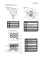
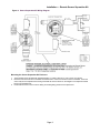
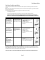
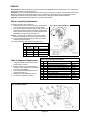
Introduction
Elements Drawings 1a, 1b, 1c
1a GasPoint Monitor
Item
1b Control Bay
Item
Description
1
Cable Conduit Access
2
Explosion-proof Enclosure
3
Sensor
4
Calibration Pushbutton
1c Liquid Crystal Displays
Function
1
Edit buttons: Increment / Decrement
Value
2
OK button: Access User Setpoints, or
Save Displayed Values
3
Faceplate Security Screw
4
Low Light Sensor
5
High / Low Alarm Settings: User Label
6
Slip Hinge
Item
Page
Page 33
Function
1
Numeric Reading
2
Units of Measure (ppm or %)
3
Alarm Level / Type
4
Increment / Decrement Prompt
Arrows
5
Set Value Arrow Prompts
6
Sensor Advice
7
Span Advise Icon
8
Automatic Zero Advise Icon
9
Apply Gas Advise Icon
Installation — Sensor Location
Sensor Location
Several factors should be considered when selecting locations to install sensors. The following general suggestions
should be considered to assure the detection of the target gas. Select the most suitable location for each sensor.
Air Currents: If there are fans, wind, or other sources of air movement, gases may tend to rise or collect in
certain areas of a facility. The local air currents should be assessed to aid in selecting the sensor location. In
outdoor situations considerations such as prevailing winds should be accounted for. Air convection can often be
more important in determining gas concentrated areas than factors of Vapor Density.
Vapor Density: When there are no air currents in the area, sensor placement may be affected where the gas
(vapor) to be monitored is lighter or heavier than air. For gases lighter than air, we suggest approx. 12 in.
(30 cm) above the level of a potential gas release, or close to the ceiling or roof in indoor installation. For gases
heavier than air, we suggest 12 in. (30 cm) below the release site, or near the floor or ground . Gases with a
density equal to air or slightly greater than air will tend to rise, particularly when air currents are present.
Gas Emission Sources: As a rule, at least one sensor should be located in close proximity to each point
where a leak is likely to occur. This is particularly important when a liquid having a low volatility is monitored.
Environmental Factors: Designed for rugged outdoor use consider the following in selecting locations. Install
sensors where they will be protected from wind, dust, snow, water, vibration and /or shock. Observe the
operating temperature range of the sensor (listed in the specifications).
Page 4
GasPoint
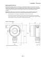
Installation — Enclosure
Mounting the Enclosure
Modular design simplifies installation of the GasPoint. The transmitter main board is mounted to the inner control
door which is equipped with slip hinges. The transmitter back enclosure contains the relays and power board and is
equipped with a threaded 3/4 in. NPT conduit fitting outlet and pre-drilled mounting flanges. Power and signal lines
connect to the plug-in terminal block on the power board. The GasPoint may be disassembled, simplifying
installation.
Recommend: Qualified personnel should perform the installation according to applicable electrical codes,
regulations and safety standards. Ensure correct cabling and sealing fitting practices are implemented.
1.
Install the GasPoint. The predrilled mounting flanges: I.D. 0.25 on 5.5 inch centers.
It is preferable to attach the transmitter to a wall or bracket, using bolts through the two mounting holes.
These mountings however, may be omitted if the electrical conduit is sufficiently rigid to support the weight
of the transmitter. The sensor should never be installed pointing upwards.
Figure 2: Outline Drawing
1 Mounting Holes (0.250 inch diameter)
Page
Page 35
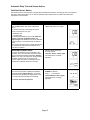
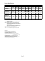
GasPoint — System Design Specifications
Installation
System Design Specifications:
Supply Voltage:
12 to 32 volts
Power Consumption: Catalytic Combustible Sensors: 100 mA @ 24 VDC
IR Combustible Sensors: 75 mA @ 24 VDC
Toxic /Oxygen Sensors: 40 mA @ 24 VDC
Relays: 50 mA per relay (150 mA total)
Memory:
Non-volatile memory, a battery back-up is not necessary to retain values in the event of
power
outages.
Loop Resistance:
650 ohms maximum
Cable
4-20 mA: 3 conductor, 14 to 24 AWG; Relays: 3 conductor, 14 to 24 AWG
Sensor Separation Kit: 4 conductor, 16 to 22 AWG
Relays:
5 amp at 24 VDC or 115 VAC SPDT; LOW, HIGH and FAULT
Low/High Relays: Field selectable for normally energized/de-energized; latching/non-latching
Fault Relay: Energized; Non-latching
Sensor Separation Kit: Transmission Distances. See Table
Cable Installation
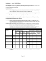
Transmission Range: The distance the 4-20 mA signal can travel is dependent on several factors including
the cable gauge. Maximum cable resistance is 650 ohms less the controller resistance.
The Tables below assume a constant 24 volt power supply (at 20°C) , copper wire and a Controller resistance of
250 ohms. The signal range from the Controller to the GasPoint takes into account the return loop, the distance
shown is from the Controller to the Transmitter. (Note the BW CR-4000 Controller has a resistance of only 120
ohms)
Table 1A: Transmitter with Catalytic/IR Combustible Sensor
(Maximum cable Lengths between Controller and Transmitter )
Conductor Size
Sq mm
AWG
0.64
22
0.75
20
1.0
1.5
Relays Not Used
feet
One Relay Connected Two Relays Connected
feet
3,356
1,022
2,368
722
1,830
557
1,491
454
5,336
1,626
3,767
1,148
2,910
887
2,371
722
18
8.476
2,583
5,983
1,823
4,623
1,409
3,767
1,148
16
13,474
4,106
9,511
4,106
7,749
2,240
5,988
Ic Current Factor
meters
0.12
feet
meters
Three Relays Connected
meters
0.17
feet
0.23
meters
1,825
0.28
Table 1B: Transmitter with Toxic/Oxygen Sensor
(Maximum cable Lengths between Controller and Transmitter )
Conductor Size
Relays Not Used
AWG
meters
feet
meters
0.64
22
6,712
2,045
3.661
1,115
2,517
767
1,917
584
0.75
20
10,953
3,253
5,821
1,774
4,002
1,219
3,049
929
1.0
18
16,953
5,167
9,247
2,818
6,357
1,937
4,843
1,476
1.5
16
26,948
8,213
14,699
8,213
10,105
3,080
7,699
2,346
0.06
0.110
feet
meters
Three Relays Connected
Sq mm
Ic Current Factor
feet
One Relay Connected Two Relays Connected
0.160
feet
meters
0.210
For other operating parameters use the formula below to establish the transmission range.
Formula: Maximum Distance = {((VP — VT)/Ic)-RC}/(2xRL)
Where:
VP = power supply voltage (minimum)
VT = transmitter supply voltage (minimum) 12 volt
Ic = current through conductor See table 1A and 1B for factors
RC = total controller resistance
RL = line resistance per 350 meters (1,160 ft)
Page
Page 36
GasPoint
Installation—Cable Installation
4-20 mA Loop Installation
Cable Routing:
Separate cables are required for each GasPoint. In classified areas cable should be in conduit or
be approved hazardous location cable.
Power Supply:
Ensure power supply meets the minimum requirements of all components of your system
(i.e. alarms, relays, etc.). BW recommends that the power supply be regulated.
Caution:
Polarity must be observed. If the RETURN and +24 volt wires are reversed the GasPoint
transmitter will not work. Do not apply electrical power to the GasPoint until all connections are
made, the sensor is in place and the transmitter is complete.
1.
2.
3.
Remove the GasPoint cover, open the inner hinged control door and remove, if desired.
Attach the conduit if applicable and pull cable(s) into the enclosure.
Connecting the 3-pin Power Terminal Block
Return (R): 4-20 mA signal to the labeled terminal
Supply (V): (+) positive (12-32 volts) to the labeled terminal
Ground (G): Ground wire to the labeled terminal
Note 1: (If using shielded Cable): To avoid radio frequency interference, the shield (including mylar) must be
grounded. Simply tying a bare drain wire to ground will not ground a shield. Keeping the shield as short as possible,
tie the shield to the internal grounding screw. Tie any unused wires to ground.
Relay Cable Installation
GasPoint is equipped with three relays: Low Gas Alarm, High Gas Alarm and Fault Alarm. Select to connect the
applicable relays required in each situation. Relay connections are labeled: NO (Normally Open), C (Common),
NC (Normally Closed). Attach wires as required to the applicable terminals.
Note 2: The Fault relay connections are reversed.
Note 3: Set Alarm Dipswitches before applying power. Once power is applied, if desired, change the Alarm Setpoints
Connecting the Controller and Power Supply
Ensure the GasPoint transmitter is complete with external cover in place before applying power. Follow the
procedures and recommendations in the Control Systems Manuals to complete installation.
1.
2.
Ensure the GasPoint is tied to the Controller ground, to the Earth ground and to the Negative Terminal of the
power supply.
Attach wires to the Controller and Power Supply as shown in the wiring diagram.
Remote Sensor Separation Kit
The GasPoint Sensor Separation Kit can be mounted at the following distances dependent of cable size.
Table 2: Distances for Sensor Separation Kit equipped as Follows:
Conductor Size
Sq mm
AWG
Catalytic/IR Combustible
Sensor
feet
meters
Toxic/O2 Sensor
feet
meters
0.64
22
619
188.5
1,548
472
0.75
20
985
300
2,463
750
1.0
18
1,564
476
3,912
1,174
1.5
16
2,487
758
6,218
1,895
Page
5
Page 37
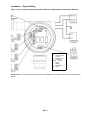
Installation — System Wiring
Figure 3: System Wiring Diagram (Exception GasPoints equipped with Communication Modules)
LEGEND
NC - Normally closed
C
- Common
NO - Normally open
V
- 12-32 VDC
G(Gnd) - Ground
R
- Return
Vx - Voltage
Tx - Transmission
Rx - Return
Exception Note: For wiring GasPoints equipped with the MODBUS Communication Expansion Module see applicable
Manual.
Page 8
Installation — Remote Sensor Separation Kit
Figure 4: Sensor Separation Kit Wiring Diagram
Mounting the Sensor Separation Kit Enclosure
1.
2.
3.
The Separation Kit is equipped with predrilled flanges: I.D. 3065 (7.68 mm) on 4.35 in (10.6 mm) centers.
Disconnect the wires from the Transmitter terminal block and remove the sensor from the Transmitter. Screw the
sensor fully into the Separation Kit housing and install the wires as shown on the diagram to the adjacent terminal
block in the Separation Kit.
Install cable as shown. Ensure correct cabling and sealing fitting practices are implemented.
Page
Page 39
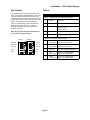
Installation — Select Field Settings
Factory Settings: The GasPoint is calibrated and tested before shipping. Prior to shipping they are factory set to
the commonly used values. To change the factory default settings see the applicable section:
The following settings are field selectable:
Dip Switch Overview
1. Calibration Time Delay: To set span, select a time delay of 30 seconds or 6 minutes. For remote calibration use
the 6 minute setting to allow time for the gas to reach the sensor. To save time and calibration gas,
GasPoint will begin the Span procedure when it senses the calibration gas.
Note: The factory default is 0.5 minutes (30 seconds). See Dipswitch 3 (CAL TIME) to change to 6 minutes.
2. Measuring Range: Select from up to four measuring ranges by setting Block 1 switch 4 and switch 5 to open or
closed. Both switch 4 and 5 are factory set to "open". See table below for selections
3. LOW and/or HIGH Relays: Select Non-latching or Latching. Factory default is set to open (non-latching).
4. LOW and/or HIGH Relays: Select De-energized or Energized. Factory default is set to open (de-energized).
Changing the Alarm and Calibration Gas Setpoints
5. Gas Alarms: Gas alarm levels are set to OSHA (Occupational Health and Safety of America) standards prior to
shipping. GasPoint is equipped with two alarm levels LOW and HIGH. To set, select (two, one or
none) alarm levels and set selected levels to any values desired. To change them see Setting Alarm
Setpoints. Factory defaults are listed below
6. Calibration Gas Concentration Level: To facilitate Auto Span, the calibration gas concentration expected is
preset. It can be changed at any time for the toxic and combustible gas Sensors. Set the standard
generally used in your facility. See Automatic Calibration Routine to change the value.
The Oxygen Sensor span is set to 20.9% and cannot be adjusted (For O2 calibrate in normal 20.%
ambient air or if the atmosphere may be deficient or enriched use Pure Air calibration gas.
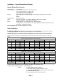
Table 3: Factory Default Settings; Select Measuring Ranges
Gas Sensed
Units of
Measure
Select Measuring Range:
Factory
Default
O—O
Or Select
4. Closed
5. Open
1
Or Select
4. Open
5. Closed
2
Or Select
4. Closed
5. Closed
3
4
Alarm Setpoints
Calibration Gas
Factory Defaults
(Field Settable)
Factory Default
Value Level
Expected
Note1:
LOW
HIGH
Combustibles 0-100% LEL
% LEL
0 to 100
N/A
N/A
N/A
10%
20%
50% LEL
Hydrogen Sulfide
ppm
0 to 100
0 to 50
0 to 500
0 to 20
10 ppm
15 ppm
20 ppm
Carbon Monoxide
ppm
0 to 500
0 to 1000
0 to 100
0 to 50
35 ppm
200 ppm
200 ppm
Ammonia
ppm
0 to 50
0 to 100
0 to 500
0 to 999
25 ppm
50 ppm
50 ppm
Nitrogen Dioxide
ppm
0 to 50.0
0 to 10.0
0 to 20
0 to 99.9
2.0 ppm 5.0 ppm
10.0 ppm
Hydrogen Cyanide
ppm
0 to 20.0
0 to 50.0
0 to 100
N/A
4.7 ppm 10 ppm
15 ppm
Sulfur Dioxide
ppm
0 to 100
0 to 50
0 to 20
0 to 10
2 ppm
5 ppm
20 ppm
Oxygen
% by vol.
0 to 30.0%
N/A
N/A
N/A
19.5%
18.5%
20.9% Ambient
air or pure air
Note 1: Calibration Gas Factory Default Values — It is recommended that the default values be changed if
selecting higher measuring ranges than the factory default measuring range. See page 13 and page
26 (Note 2).
Page
Page 10
3
Installation — DIP Switch Settings
Dip Switches
Table 4:
The dipswitches are located on the upper control
board. To access the dipswitch banks, remove the
top of the explosion-proof enclosure, loosen the
control board access screw (located just below the
buttons) and open the control door which is on slip
hinges. The dipswitches are clearly labeled.
Caution: The GasPoint must be powered down
before removing the outer cover. If it is in a
classified area either remove the GasPoint or
declassify the area.
Note: Any latched relay will be released upon
one push of the external button.
OPEN
5
4
3
2
3
Block 1: Calibration and Measuring Ranges
1
OPT B
Not used
2
OPT A
Not used
3
CAL TIME
Calibration wait period
Open—0.5 min.
Closed—6 min.
4
RANGE LO
Set Measuring Range
5
RANGE HI
Set Measuring Range
1
HI L
(High alarm)
Open—Non-latching relay
Closed—Latching relay
2
LOW L
(Low alarm)
Open—Non-latching relay
Closed—Latching relay
3
FAULT E
Not used. (See Specifications)
4
HI E
(High alarm)
Open—De-energized relay
Closed—Energized relay
5
LOW E
(Low alarm)
Open—De-energized relay
Closed—Energized relay
FA ULT E
LOW L
1
OPT B
OPEN
OPT A
HI E
2
CAL TIME
LOW E
1
RANGE LO
4
5
RANGE HI
Function
Block 2: Gas Alarm Relay Settings
Block 2
Block 1
Dip Switch
HI L
Page 11
Power-Up
Connecting the Controller and Power Supply
Ensure the GasPoint transmitter is complete with its external cover in place before applying power. Follow the
procedures and recommendations in the Control Systems Manuals to complete installation.
Note: Ensure the GasPoint is tied to the Controller ground, to the Earth ground and to the Negative Terminal of the
power supply.
1.
Attach wires to the Controller and Power Supply as shown in the wiring diagram (page 6). When power is
applied the GasPoint automatically turns on.
!
All elements of the LCD will light and flash twice. Then each icon will light separately and stay on until all are
displayed. The LCD backlight will activate.
!
The word Test will appear on the LCD. The GasPoint then begins a 2 minute countdown
from 999 to 000.
During the countdown to normal operations the GasPoint will communicate with the sensor,
determine the sensor type, test sensor integrity of the Toxic and/or combustible sensors (Not
applicable to oxygen sensor) test all circuitry and allow the sensor to stabilize before normal
operation begins. The transmitter will determine the sensor range and the sensor life remaining.
Once the initialization is complete, the GasPoint enters normal operational mode (in the system
loop) providing a signal to the controller of the gas present.
!
After countdown, the LCD will display the current LOW alarm and HIGH Alarm
Setpoints. Each Alarm setpoint is displayed for 4 seconds. To review them,
press and release the external pushbutton after normal operation begins.
!
Upon a successful Self-Test, the transmitter will automatically enter normal
operation and display the ambient gas present. The backlight remains on for
5 seconds after normal operation begins. In the event the unit fails the self-test
(see Fault Alarm Conditions).
Controller Calibration
Follow the procedures and recommendations in the Control System Manual to calibrate the Control System.
1.
Calibrate the Control System (see your Control Manuals). Set the controller as follows:
4 mA = ZERO
20 mA = FULL SCALE
Next, calibrate the GasPoint with gas. Then, see Changing the Alarm Setpoints.
Page
Page 12
3
Changing Setpoints
Changing the Alarm Setpoints and Calibration Gas Setpoints
The Setpoint Mode allows the user to change the calibration gas concentration level, the low alarm setpoint and the
high alarm setpoint. See "Select Field Settings" (page 8) for factory default settings. To change the values:
1.
2.
Screw off the enclosure top. (Allows access to edit buttons).
Press OK button for 2 seconds to access Setpoint Mode and change factory default settings.
GAS ALARM SETPOINTS:
1. GasPoint is equipped with two setpoints LOW and HIGH.
2. If only one setpoint is required, set one level to zero to turn it OFF. Set the
other setpoint as desired.
Note: If both LOW and HIGH are set to the same value, the Gaspoint will trigger
a HIGH alarm condition if that setpoint is met or exceeded.
3. To turn OFF both alarm levels set both setpoints to zero.
Changing Setpoints
LCD Icons Displayed
CHANGE THE CAL GAS CONCENTRATION LEVEL
1. The LCD will first display the current cal gas
concentration value. Press OK to accept the current
displayed value or proceed to change the value.
Numeric display shows current
calibration gas value expected.
Set new Calibration Gas Level
Press ▲up button to increase value.
Press ▼down button to decrease value.
Press OK button to accept the new value
displayed on the screen and end set calibration
gas level.
Note: O2 The factory default Span is set at 20.9%
“Set Span” advice flashes
Gas Cylinder icon flashes
Up/down arrow icons flash
Gas monitored is constantly
displayed
CHANGE THE LOW ALARM SETPOINT
1. The next screen displays the current Low Alarm
Setpoint as shown. Press OK to accept the current
displayed value or proceed to change the value.
Set new Low Alarm Setpoint
Press ▲up button to increase value.
Press ▼down button to decrease value.
Press OK button to accept the new low alarm
value displayed on the screen.
Numeric display shows current
Low Alarm Setpoint
CHANGE THE HIGH ALARM SETPOINT
1. The next screen displays as shown.
Numeric display shows current
High Alarm Setpoint
“HIGH ALARM Set” advice
lights
Up/down arrow icons flash
Gas monitored is constantly
displayed
Set new High Alarm Setpoint
Press ▲up button to increase value.
Press ▼down button to decrease value.
2. Press OK button to accept the new high alarm
value displayed on the screen. GasPoint will return
automatically to normal operation and display gas
currently present.
3.
Display
“LOW ALARM Set” advice
lights
Up/down arrow icons flash
Gas monitored is constantly
displayed
Settings Complete—Verification (optional)
Test the GasPoint using a gas cylinder other than the one used in the calibration steps. The gas concentration
should not exceed the sensor's detection range (see page 8). Confirm that the display shows the expected concentration.
O2 (Oxygen) Note 1: Oxygen Low and/or High gas alarm setpoints can be set to either enrichment and/or defi-
ciency alarms as desired. If the alarm setpoint is set to below 20.9% (deficiency alarm) an alarm will be triggered if
the concentration present is below 20.9%. If the alarm setpoint is set to above 20.9%, an alarm will be triggered if
the concentration present exceeds 20.9%. You can choose to set both alarms above or below 20.9% or one alarm
above and one below 20.9 % as desired.
Page
Page
Page 13
39
Operation
Normal Operation
The GasPoint provides continuous monitoring for the target gas. In the event of power failure,
the GasPoint will automatically reset itself back into the system loop after power is restored.
The GasPoint has non-volatile memory and will not be affected by a power disruption. All
programmed information is protected with total memory retention.
Operation
Recommend: BW recommends GasPoint be calibrated before first time use
The GasPoint runs a daily self-diagnostics including a Toxic and combustible sensor integrity test Not applicable to
oxygen sensors). If the GasPoint fails any of the diagnostics, the transmitter will then provide the proper output and
LCD display screen for that particular fault.
LCD: The LCD shows the current ppm or % reading of the target gas present.
View Alarm Setpoints: To view the alarm setpoints at any time:
1. Press the external pushbutton (one second only) and release. The LCD will display current alarm setpoints
LOW and then HIGH.
Relays:
! Fault: The fault relay will always be energized under normal operations. The relay will de-energize only if the
GasPoint is addressing a fault condition or when power is released.
! Low/High Gas Alarms: The gas alarm relays connected will be energized or de-energized (latching or nonlatching) according to the GasPoint dipswitch settings you have selected.
Reset Latched Relay Alarm (Alarm Acknowledge): If a gas alarm relay has been set to latching mode,
acknowledge the alarm condition:
1.
Press the external pushbutton (for one second only) until the display reads Low Alarm setpoint, then release
the external button. The GasPoint will release the latched alarm(s), and display the current LOW and HIGH
alarm setpoints.
Note: If an alarm condition exists, GasPoint will not allow the user to reset a latched alarm or display the alarm
setpoints.
Output: The 4-20 mA loop output will be normal (from 4 to 20 mA according to calibrated values) except in a fault
condition.
Backlight: The backlight will activate in low light conditions. When ambient light conditions return to normal the
backlight will turn off automatically.
Page
Page 14
3
Gas Alarms Advice
Gas Alarm Conditions and Advice
If the current gas concentration meets or exceeds either alarm setpoint, the GasPoint gas alarm functions will
activate.
Note: If both or either gas alarm is turned OFF (set to zero or set to the same value) then no gas alarm condition
will exist for that alarm level.
The following alarm advice will activate in any gas alarm condition (LOW or HIGH):
The backlight will activate.
The 4-20 mA loop output will be normal (from 4 to 20 mA according to calibrated values)..
When the alarm condition no longer exists, GasPoint will exit alarm mode and enter normal operations.
Exception: If a relay is set to the latching position on either Low or High gas alarm, the relay will
remain “on” until the alarm is reset (ACKNOWLEDGED). Press the external button to reset the relay.
Alarm Condition
LOW GAS ALARM
If the current gas
concentration present
meets or exceeds the
low alarm setpoint.
Alarm Relay
LCD Icons Displayed
Low Alarm Relay triggers
field interface if the relay
is connected and a low
alarm setpoint is entered.
Numeric display will show the gas
currently present (ppm/%)
LOW icon lights
ALARM icon flashes
Gas type monitored is constantly
displayed
High Alarm Relay triggers
a field interface if the
relay is connected and a
high alarm setpoint is
entered.
Numeric display will show the gas
currently present (ppm/%)
HIGH icon lights
ALARM icon flashes
Gas type monitored is constantly
displayed
*See O2 Note below
HIGH GAS ALARM
If the current gas
concentration present
meets or exceeds the
high alarm setpoint.
*See O2 Note below
OVER RANGE
(over level or over
range)
GAS CONDITION
If the gas concentration
present meets or
exceeds the full
measuring range.
Display
OL icon lights
Gas type monitored is constantly
displayed
Note: If the alarms are turned OFF,
then no alarm icons will display
O2 (Oxygen) Note: (See Oxygen note 1 on page 13) An oxygen alarm level will depend on which
alarm setpoints have been set to Low and High. The oxygen Low and/or High gas alarm setpoints are user
selectable for either enrichment and/or deficiency alarms as desired.
CAUTION: HIGH OFF-SCALE READINGS MAY INDICATE AN EXPLOSIVE CONCENTRATION.
Page 15
Automatic Daily Test and Sensor Advice
GasPoint Sensor Advice
The GasPoint sensor communicates constantly with the GasPoint transmitter, providing gas level concentrations
and sensor status information such as, self-test pass/fail, sensor replacement, life expired and other status
information to the transmitter.
Sensor
LCD Icons Displayed
Numeric display will read “00”
“Auto Test” advice icons light
AUTOMATIC DAILY SENSOR SELF-TEST
(FOR COMBUSTIBLE AND TOXIC SENSORS
ONLY)
The self-test will not be run if background gas is
present. The self-test is run upon:
initialization and
on a daily basis.
The self-test period lasts for 45 seconds. While the
self-test is running, the GasPoint does not
respond to gas. The GasPoint can not be calibrated
during a self-test or 10 minutes before the self-test
begins.
Note: Sensor Fail Advice: If the unit fails the self-test.
The GasPoint will enter Self-Test Fail Mode. See
Fault Alarm Conditions.
SENSOR REPLACEMENT ADVISE
The sensor provides the expiry information to the
transmitter. Once the sensor has reached the expiry
date, the GasPoint transmitter will display “Replace
Sensor” on its LCD. This will last for 90 days and the
transmitter will send a 3.8 mA signal from its
4-20 mA output when there is no background gas.
Otherwise the GasPoint will function normally.
Numeric display shows gas
currently present
“Replace Sensor” advice lights
Gas monitored is constantly
displayed
EXPIRED SENSOR ADVISE
Once the 90-day period is complete the GasPoint
system will display “Expired Sensor”, the monitor
will shutdown and the GasPoint triggers fault mode
(2 mA output and the fault relay de-energized).
FAULT icon lights
ALARM icon flashes
3 bar ( - - - ) icon flashes
“Expired Sensor” advice lights
Gas monitored is constantly
displayed
The sensor must then be replaced.
Page 16
Display
Fault Alarm Advice
Fault Alarm Conditions and Advice
In the event of a fault condition, the fault alarm will trigger activating any connected field interface. GasPoint will
advise which fault condition has occurred.
Under Fault Alarm conditions:
The non-latching fault relay be "on" de-energized during a fault condition.
The backlight will activate.
When the problem is corrected, GasPoint automatically returns to normal operation.
Fault Condition
4-20 mA
Output
LCD Icons Displayed
SENSOR SELF-TEST FAIL
(The self-test has failed)
2.00 mA
Three (3) bars will flash on numeric display.
FAULT icon lights
ALARM icon flashes
"Sensor Fail" advice lights
Gas type monitored is constantly displayed
SENSOR FAULT
(no communications)
2.00 mA
Numeric display will read the last value (ppm/%)
present before sensor fault occurs
FAULT icon lights
ALARM icon flashes
"Sensor Fail" advice lights
Gas type monitored is constantly displayed
SENSOR DRIFT
2.00 mA
Numeric Display will read "00"
FAULT icon lights
ALARM icon flashes
“Sensor Error” advice lights and flashes
Gas type monitored is constantly displayed
Page 17
Display
Calibration
Calibration Guidelines
When calibrating the GasPoint, adhere to the following guidelines.
Calibration accuracy is never better than the calibration gas accuracy. BW Technologies recommends a
premium-grade calibration gas. Gases with NIST (National Institute of Standards and Technology) traceable
accuracy will improve the validity of the calibration. Do not use a gas cylinder beyond its expiration date.
Calibrate a new sensor before use. Allow the sensor to stabilize before starting calibration (approx. 5 minutes).
Calibrate the GasPoint on a regular schedule. (BW recommends once every 3 months, depending on use and
sensor exposure to poisons and contaminants.)
Calibrate the GasPoint if the ambient gas display value varies at startup.
It is best to calibrate the sensor before changing alarm setpoints.
Calibrate only in a clean atmosphere, which is free of background gas.
Calibration Diagnostics Protection
If calibration is incomplete the GasPoint automatically returns to normal operation, all prior (former), calibration
data is retained. Common cause for the GasPoint to refuse calibration or for an incomplete calibration include:
Background Interfering gas is present
If interfering gas is present during Auto Zero. GasPoint will
refuse to Auto Zero and exit calibration routine.
Combustible and Toxic Sensors: Wait for GasPoint to
return to normal operation. Apply Pure Air (Zero gas)
and repeat calibration.
Calibration Gas cylinder runs empty during calibration
Wait for unit to return to normal operation. Replace
empty gas cylinder with full cylinder and repeat
calibration.
Calibration Gas concentration is too low or too high
Calibration gas concentration is not within expected
parameters—either the concentration of applied gas (ppm
or %) is too high or too low.
GasPoint will refuse to set span if the calibration gas is not
within expected parameters and will exit.
Change the value to equal the calibration gas
concentration being applied.
Gas applied at the wrong time.
Gas is applied before requested to do so, or if, gas is
applied during auto zero, GasPoint will refuse to proceed
and exit the calibration routine. The prior (former) auto zero
value will be retained.
Restart the calibration routine and apply gas only
when the gas bottle icon flashes.
Calibration Tubing: Use teflon, or stainless steel hose on
all electrochemical sensors.
Caution: Tygon will poison a Catalytic Combustible sensor
over time.
Remote Calibration: The length of time depends on the
length of hose the calibration gas must travel. If the wait
period is longer than 30 seconds, the CAL TIME Dipswitch
must be set to 6 minutes.
To save gas and time, GasPoint will begin span when it
senses calibration gas.
Apply calibration gas for approximately 2 minutes plus the
time estimated for the gas to reach the sensor.
Page 18
Calibration
Automatic Calibration Routine
Calibration can be run at any time during normal operation except the self-test period (from 10 minutes before the
self-test until the self-test is complete). Calibration is a one man operation and virtually automatic.
Note: For Calibration gas concentrations and flowrates for each gas, see Appendix A (page 25)
To Calibrate perform the following steps:
LCD Icons Displayed
START CALIBRATION
1. Press and hold the external button down while
the LCD displays the Alarm Setpoints.
Continue to hold down until the display reads
“CAL“ (approx. 5 seconds) and then release the
button.
The 4-20 mA output will be 3 mA throughout
calibration. Calibrating the GasPoint will not
cause false alarms at the controller.
First, the LOW and HIGH alarm
setpoints will be displayed (8
seconds approx)
Next, the CAL icon lights for 3
seconds
Gas type is constantly displayed
Backlight is activated
AUTO ZERO
Numeric display will read “00”
"Auto Zero" advice flashes
Gas monitored is constantly
displayed
The GasPoint will then take a zero level reading
The display is as shown.
2. Combustible and Toxic Sensors: If background
gas is present, apply zero gas (pure air or 100%
nitrogen) to zero the sensor. Restart the
Calibration sequence.
3. Oxygen Sensor: Gas is not required. Auto Zero
sequence will take 30 to 60 seconds.
AUTO SPAN
3. Insert cal cap (1) and apply gas to the sensor
for approx. 2 minutes (Ammonia 5 minutes).
See Appendix A for concentrations and
flowrates.
4. When the countdown "300" to "00" begins Span
is complete, disconnect the gas.
If Span Fails: Check calibration gas cylinder
used and concentration expected. Replace the
cylinder and/or change the cal gas expected
value, if required. Recalibrate.
Oxygen Sensor: Use Pure Air Calibration Gas
(20.9% O2 ) in case o of deficient ot enriched
Exiting Calibration Routine (Fail or Error):
Auto Zero Fail: If the "Fail" icon lights, the LCD
will display a countdown from "300" to "00",
before GasPoint begins normal operation.
AutoSpan Error: If the "Error" icon lights, the
LCD will display a countdown from "300" to "00",
before GasPoint begins normal operation.
Note: In either fail condition occurs, all previous
information values are retained. Retry.
Numeric display will show
calibration gas value expected
Gas cylinder icon flashes
"Span" advice lights
Gas type is constantly displayed
After a successful calibration
GasPoint automatically returns to
normal operation and displays the
current reading ppm or % present.
Auto Zero: If the target or an
interfering gas is present GasPoint
will refuse to auto zero. The “Fail”
icon lights. The “Fail” icon will also
light if the external pushbutton is
pressed during auto zero.
Span: If the cal gas is not within
expected values, the GasPoint will
refuse to span. The "Error" icon
will light.
Page 19
Display
MAINTENANCE
SERVICE
Page 21
Maintenance
To keep the GasPoint in good operating condition, perform the following basic maintenance as required:
Calibrate, test, and inspect the GasPoint at regular intervals and after exposure to high concentrations.
Keep an Operations Log of all maintenance, calibrations, and alarm events.
Clean the exterior with a soft damp cloth. Do not use solvents, soaps, or polishes.
Do not immerse the GasPoint in liquids.
Cleaning a Sensor
The sensors are equipped with a stainless steel sintered or a hastelloy sintered flame arrestor screen (dependent on
gas). Clean only with a dry brush being careful not to clog the screen. Replace the sensor if the screen is plugged.
Clearing a Sensor
The sensor has a high degree of resistance to common vapors and gases. The sensor will most likely clear itself if you
remove the GasPoint to a clean environment and wait 10 to 30 minutes. Do not expose a sensor to the fumes of
inorganic solvents (such as paint fumes) or organic solvents.
Troubleshooting
With enhanced diagnostics GasPoint provides extensive fault analysis and fault advice, see Fault Alarm Conditions and
Advice. The troubleshooting chart deals with other factors and is to be used a guide. Prior to reaching any conclusion that
problem may exist, check the following.
!
!
All terminal blocks are fully seated on the boards.
Power and signal connections are correct and complete.
Troubleshooting Chart
Fault
Probable Cause
Solution
No response to gas
Sensor screen dirty
Clean or replace sensor
Apparent false alarm
Puff of gas
Monitor is functioning
Not properly calibrated
Re-calibrate
Solvent fumes or interference
from high levels of interfering gas
Radio frequency interference
Remove source
Maximum distance reached
Verify loop resistance, change wire AWG
or increase supply
No signal at controller
Page 22
Check grounds and shielding and correct.
SERVICE
Disassembling: Observe all safety and electrical codes and regulations before removing front cover. Unscrew the
thumbscrew and open the service bay door.
Assembling: When re-assembling the GasPoint ensure that it is electrically complete. Close the Service Bay Door.
Ensure the thumbscrew is aligned and tighten it down. Replace the outside glass cover. Re-apply power and reinitialize the transmitter Power-Up procedure (see Power-Up). Change the Alarm setpoints if desired.
Important: Calibrate the GasPoint whenever a component is replaced.
Sensor Assembly Replacement
To replace the entire sensor assembly:
1. Disconnect the wires from the 4-pin plug-in terminal block
at J5 on the power board and remove the old sensor.
2. Feed the new wires through the opening. Fully screw in the
new sensor. Attach the wires to the plug-in terminal block.
Ensure that all colored wires are correctly matched to the
board labels from left to right. See Figure 4.
Caution: Check that all connections are correct. Incorrect
wiring may damage the sensor and/or the power board.
4. See Transmitter Dipswitch Settings (Table 4) to select a
measuring range if required.
For sensor replacement part numbers see Appendix A.
Fig. 5: Sensor Wiring Diagram
Sensor Wiring Configuration
#
1
2
3
4
Board
Label
Pwr 8 VDC
TX
RX
GND
Wire
Color
Red
Grey
White
Black
Description
Power 8 VDC (left)
Transmission
Signal
Ground (right)
Other Component Replacement
1.
2.
3.
4.
5.
Unplug the sensor terminal block from the
power board if required.
Replace component, ensuring all wiring
connections are complete and re-assemble
as shown. See Installation.
Ensure all field selectable options are set
(measuring range, etc.).
Apply power and re-initialize Power-Up.
Set the alarm setpoints if required.
Table 5: GasPoint Replacement Parts
#
QTY.
DESCRIPTION RATING/TOL
Part #
1
2
3
4
5
6
7
8
9
10
1
1
1
3
1
2
1
1
1
1
External faceplate window cover
Internal hinged door faceplate cover
Transmitter main LCD board (PCB)
#6-32 x 1/4 inch machine Phillips screws
Threaded stand-off –accepts thumbscrew
#6-32 x 1/4 inch machine Phillips screws
Plug-in ribbon cable
Power/Relay Board (PCB)
Transmitter housing c/w external switch
Sensor Assembly
M1147
M2345
E2737/2
M0262
M2394
M0262
E2802
E2739/1
M2346K
Appendix A
Fig 6: Assembly Drawing
Page 23
APPENDIX A
Sensor Information
Sensor Specifications ....................................................
Order Numbers ..............................................................
Relative Sensitivity of combustible gases . ...................
Instrument Specifications ...........................................................
26
26
27
28
A
P
P
E
N
D
I
X
Page 25
A
Sensor Specifications
Operating and Calibration Specifications
Specifications
Repeatability % of signal
Op Temperature Range
ºC
ºF
% of signal loss per month
Catalytic
Combustibles
Zero:
Span:
LCD Increments
Calibration: Note2
Flow Rate (min). mls/minute
at a % or ppm reading of:
Sensor:
Replacement Part Numbers
%LEL
%LEL
H2S ppm
CO ppm
1
1
1
1
-40 to +70
-40 to +150
-40 to +90
-40 to +194
-40 to +50
-40 to +122
Hydrogen Cyanide
Nitrogen
Dioxide
Oxygen
SO2 ppm
NH3 ppm
HCN ppm
NO2 ppm
O2 ppm
1
<10
0.5
0.2
0.1
-20 to +50
-4 to +122
-20 to +50
-4 to +122
-20 to +50
-4 to +122
Nominal
<1
1%
Nominal
<1
1%
Nominal
<2
1 ppm
Nominal
<2
1 ppm
Nominal
<2
1 ppm
Nominal
<2
1 ppm
Nominal
<2
0.1 ppm
Nominal
<2
0.1 ppm
Nominal
<1%
0.1%
250
50% LEL
IR-RW03
250
50% LEL
SS-RW02
250
20 ppm
SS-RH02
150
200 ppm
SS-RM02
250
20 ppm
SS-RS02
500
50 ppm
SS-RA02
250
15 ppm
SS-RZ02
1,000
10 ppm
SS-RD02
250
Note:3: 20.9 %
SS-RX02
Dioxide
-20 to +50
-20 to +50
-10 to +50
-4 to +122
-4 to +122
+14 to +122
5 to 95 % non condensing
Note 1: Performance data is based on conditions at 20 ºC,
50% RH, 1013 mBar.
Note 2: Calibration Gases: It is recommended that the
Calibration Gas concentration for toxic sensors be 50%
of the selected measuring range. (Factory default
values are shown. )
Auto span. Values expected by the GasPoint for toxic
gases can be changed at any time (See page 13).
Note: 3 Oxygen Use Pure Air calibration Gas
Note 4:
Ammonia
Hydrogen Sulfide Carbon Monoxide Sulfur
0 to 100%
Non Condensing
Operating Humidity
Long Term Drift
IR
Combustibles
Do not adjust the oxygen sensor span value.
Sensors:
Toxic and Oxygen: Electrochemical
Combustible: Catalytic or Infrared (IR)
Position Sensitivity: None
Operation Pressure Range: 900 to 1100 mBar
(Atmospheric +/- 10%)
Calibration Notes: For maximum accuracy
calibrate with a mixture in the range most
measurements will be made. For most purposes a
2 minute exposure is satisfactory.
Page 26
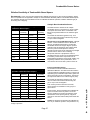
Combustible Sensor Notes:
Relative Sensitivity of Combustible Gases/Vapors
Recommend: For the most accurate measurements calibrate using the gas or vapor under investigation. Where
this is not possible see the applicable “Catalytic or Infrared Relative Sensitivity table for Combustible Gases/Vapors”.
The GasPoint catalytic and combustible sensors are calibrated to Methane (with 50% methane calibration gas) at
the factory prior to shipping.
Catalytic Bead Combustible Sensor
Catalytic Sensor Relative Sensitivity of Common
Combustible Gases/Vapors
Gas/Vapor
Relative
Sensitivity
Gas/Vapor
Relative
Sensitivity
Methane
100
Carbon
monoxide
110
Propane
60
Acetone
75
n-Butane
60
Methyl ethyl
ketone
60
n-Pentane
50
Toluene
60
n-Hexane
50
Ethyl acetate
65
n-Heptane
50
Hydrogen
100
n-Octane
50
Ammonia
145
Methanol
115
Cyclohexane
65
Ethanol
85
Leaded petrol
60
iso-Propyl
Alcohol
70
Unleaded
petrol
60
NOTE: Each sensitivity has been rounded to the nearest 5%.
Standard Model IR GasPoint Relative Sensitivity to
Applicable Combustible Gases/Vapors
Gas/Vapor
Relative
Sensitivity
Gas/Vapor
Relative
Sensitivity
Acetone
60
n-Hexane
325
n-Butane
450
Methane
100
iso-Butane
450
n-Pentane
390
Butane-1
450
iso-Pentane
390
cis-Butane-2
450
Propane
410
trans-Butane-2
450
Propanol
230
Ethane
450
Propylene
310
Ethanol
330
o-Xylene
100
Ethylene
80
m-Xylene
100
n-Heptane
325
p-Xylene
100
NOTE: This table is intended for guidance only.
Always calibrate using the gas or vapor under investigation.
The table shows the variation of the catalytic
combustible sensor on exposure to a range of gases
and vapors at the same %LEL concentration. The
figures are expressed relative to the methane signal
(=100).
The results are intended for guidance only. For a
more accurate measurement calibrate using the gas
or vapor under investigation.
Special Note on the Combustible Sensor: Catalytic
Poisons - Certain substances have a detrimental
effect on all catalytic bead sensors. The GP-WD
combustible sensor has a higher degree of poison
resistance and will outperform other catalytic bead
sensors in poisonous atmospheres. However,
catalytic sensors should not be exposed for prolonged
periods of time to lead or sulfur containing
compounds, silicones or phosphates. Action is
cumulative and may result in an irreversible decrease
in sensitivity. Certain other compounds such as
halogenated hydrocarbons and hydrogen sulfide, may
temporarily inhibit the sensor performance, but in
most cases it will recover after a period in clean air.
Infrared Combustible Sensor
The standard model IR Combustible GasPoint is
calibrated to Methane. The table shows the variation
of the IR (infrared) combustible sensor on exposure to
applicable group combustible hydrocarbon gases and
vapors at the same %LEL concentration. The figures
are expressed relative to the methane signal (=100).
The results are intended for guidance only. For a
more accurate measurement calibrate using the
gas or vapor under investigation.
Note: If the hydrocarbon desired is not listed,
special models are available for other groups of
hydrocarbons
For IR sensors, use the specified gas to calibrate the
system. IR sensors work very well in Low or NO
Oxygen Conditions. IR sensors monitors the molar
concentration of the specific gases by a physical
method. No chemical reaction takes places inside the
sensor.
Caution: IR Systems should always be calibrated as
soon as you install the system to compensate for any
change in pressure.
Page 27
A
P
P
E
N
D
I
X
A
Specifications:
3-wire, 4-20 mA gas transmitter with advanced micro-controller based circuitry
Power Input:
12 to 32 volts DC
Output Current: Normal Operation: Isolated linear 4-20 mA output
Calibration Mode: Steady 3 mA (Automatic reset to normal operation)
Fault Mode: 2 mA signal (and less)
Current Consumption:
Toxic Versions: 40 mA at 24 VDC
Catalytic Combustible Version: 100 mA at 24 VDC
Infrared Combustible Version: 75 mA at 24 VDC
Relays: 50 mA per relay @ 24 VDC
Accuracy: ± 0.1 mA @ 10°C to 50 °C (50°F to 122°F)
MONITOR:
SENSORS:
Self-Test:
Pug-in, Logic sensors M
Automatic daily self-test of toxic and combustible sensor integrity and sensor life
Oxygen: Not required
CALIBRATION:
Non-intrusive, via push-button
Auto Zero and Auto Span
DISPLAYS:
Two backlit Liquid Crystal Displays
3 digit continuous readout of the gas present (ppm or % LEL)
Alphanumeric diagnostic Status display
LCD 1:
LCD 2:
ALARM SETPOINTS: Two (2) setpoints - User selectable
RELAY CONTACTS: Three field retro-fittable SPDT relays; 5 amps @ 250 VAC
LOW/HIGH:
FAULT:
Field selectable for normally energized/de-energized and latching/non-latching
Normally energized and non-latching
CONTROLS:
Calibration:
Non-Intrusive via external pushbuttonM
Alarm Setpoints: Simple Up/Down push-buttons with LCD readout of setpoints
PHYSICAL:
Size:
Weight:
Enclosure:
Sensor:
Wiring Port:
WARRANTY:
Instrument:
Sensor:
APPROVAL:
6.8 x 7 x 4.3 in. (17 x 17.8 x 10.8 cm) including sensor
4.85 lb. (2.2 kg) approx.
Explosion-proof, anodized aluminum enclosure c/w mounting flanges
Stainless Steel enclosure
3/4 inch n.p.t.
2 years non-prorated
2 years warranty.
Approved by CSA to both U.S. and Canadian Standards: Class I, Groups, B, C, D
Approved Explosion Proof Standards UL1203; C22.2 No 152
Approved to Combustible Performance Standards ISA-S12.13 and C22.2 No. 152
DUE TO ON-GOING RESEARCH AND PRODUCT IMPROVEMENT, SPECIFICATIONS ARE SUBJECT TO CHANGE WITHOUT NOTICE.
Page 28
BW Technologies Limited Warranty
ORDER NUMBERS
BW Technologies warrants this product to be free from
defects in material and workmanship under normal use and
service for a period of two years, beginning on the date of
shipment. Parts, product repairs and services are warranted
for 90 days. This warranty extends only to the original buyer
or end-user customer of a BW Technologies authorized
reseller. It does not apply to any product which, in BW
Technologies’ opinion, has been misused, altered, neglected
or damaged by accident or abnormal conditions of operation
or handling. BW Technologies warrants that software will
operate substantially in accordance with its functional
specifications for 90 days and that it has been properly
recorded on non-defective media. BW Technologies does not
warrant that software will be error free or operate without
interruption.
Transmitters c/w Sensor Assemblies and Relays
GP-WD
GP-IR-WD
GP-HD
GP-MD
GP-SD
GP-ZD
GP-XD
GP-AD
GP-DD
Add Suffix "-SS"
Transmitter c/w Combustible Sensor
Transmitter c/w IR Combustible Sensor
Transmitter c/w Hydrogen Sulfide Sensor
Transmitter c/w Carbon Monoxide Sensor
Transmitter c/w Sulfur Dioxide Sensor
Transmitter c/w Hydrogen Cyanide Sensor
Transmitter c/w Oxygen Sensor
Transmitter c/w Ammonia Sensor
Transmitter c/w Nitrogen Dioxide Sensor
For optional Stainless Steel Transmitter
enclosure
Note: Sensor Assembly enclosures are stainless steel (standard)
Accessories and Spares:
GP-1
Gas Transmitter only c/w LCD’s and Relays (No
Sensor)
GP-SEP
Sensor Separation Kit
GP-MBUS1
MODBUS Communication Expansion Module
SS-RW02
Combustible Sensor Assembly
IR-RW03
IR Combustible Sensor Assembly
SS-RH02
Hydrogen Sulfide Sensor Assembly
SS-RM02
Carbon Monoxide Sensor Assembly
SS-RS02
Sulfur Dioxide Sensor Assembly
SS-RA02
Ammonia Sensor Assembly
SS-RZ02
Hydrogen Cyanide Sensor Assembly
SS-RD02
Nitrogen Dioxide Sensor Assembly
SS-RX02
Oxygen Sensor Assembly
GP-CAL-3
Non-conductive Remote
Calibration Cup and Splash Guard
GP-SSCAL4
Stainless Steel Remote Calibration
Cup and Splash Guard
GP-SSPLASH4 Stainless Steel Splash Guard
GPOINT-B
GasPoint Pushbutton protective boot
D1374/2
Manual
BW Technologies authorized resellers shall extend this
warranty on new and unused products to end-user customers
only but have no authority to extend a greater or different
warranty on behalf of BW Technologies. Warranty support is
available if product is purchased through a BW Technologies
authorized sales outlet or Buyer has paid the applicable
international price. BW Technologies reserves the right to
invoice Buyer for importation costs of repair/replacement parts
when product purchased in one country is submitted for repair
in another country.
BW Technologies’ warranty obligation is limited, at BW
Technologies’ option, to refund of the purchase price, free of
charge repair, or replacement of a defective product which is
returned to a BW Technologies authorized service center
within the warranty period.
To obtain warranty service, contact your nearest BW
Technologies authorized service center or send the product,
with a description of the difficulty, postage and insurance
prepaid (FOB Destination), to the nearest BW Technologies
authorized service center. BW Technologies assumes no risk
for damage in transit. Following warranty repair, the product
will be returned to Buyer, transportation prepaid (FOB
Destination). If BW Technologies determines that the failure
was caused by misuse, alteration, accident or abnormal
condition of operation or handling, BW Technologies will
provide an estimate of repair costs and obtain authorization
before commencing the work. Following repair, the product
will be returned to the Buyer transportation prepaid and the
Buyer will be billed for the repair and return transportation
charges (FOB Shipping Point).
THIS WARRANTY IS BUYER'S SOLE AND EXCLUSIVE
REMEDY AND IS IN LIEU OF ALL OTHER WARRANTIES,
EXPRESS OR IMPLIED, INCLUDING BUT NOT LIMITED TO
ANY IMPLIED WARRANTY OF MERCHANTABILITY OR
FITNESS FOR A PARTICULAR PURPOSE. BW
TECHNOLOGIES SHALL NOT BE LIABLE FOR ANY
SPECIAL, INDIRECT, INCIDENTAL OR CONSEQUENTIAL
DAMAGES OR LOSSES, INCLUDING LOSS OF DATA,
WHETHER ARISING FROM BREACH OF WARRANTY OR
BASED ON CONTRACT, TORT, RELIANCE OR ANY
OTHER THEORY.
Since some countries or states do not allow limitation of the
term of an implied warranty, or exclusion or limitation of
incidental or consequential damages, the limitations and
exclusions of this warranty may not apply to every buyer. If
any provision of this Warranty is held invalid or unenforceable
by a court of competent jurisdiction, such holding will not
affect the validity or enforceability of any other provision.
11/99
Page 29
Notes:
Page 30
t
D1374/3
E-mail: [email protected]
Visit our Web Site: www.gasmonitors.com


![121290 CR-4000 Controller User Manual [English].pub](http://vs1.manualzilla.com/store/data/005770288_1-ff1b31ed544f6d88740c7f5db9da46b2-150x150.png)