1
WASHING MACHINE
DRUM TYPE
Basic Model: Model Name:
Model Code :
SERVICE
WASHING MACHINE
WF316LAS
WF316BAC
WF316LAW
<FRONTIER 1 PROJECT>
WF326***
WF306***
WF316***
WF317***
<MARS 1 PROJECT>
WF206***
WF317AAW/XAA (FRONTIER1)
WF206BNW/XAA (MARS1)
Manual
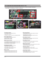
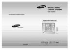
THE FEATURE OF PRODUCT
1. SilverCare
2. SuperSize Capacity
3. Direct Drive Motor
4. Child Lock
WF306LAW
WF206LNW
5. My Cycle
Refer to the service manual in the GSPN (see the rear cover) for the more information.
CONTENTS
1. PRECAUTIONS
1-1. SAFETY PRECAUTIONS.....................................................................................................................................1-1
1-2. PRECAUTIONS UPON INSTALLATION..............................................................................................................1-2
2. PRODUCT SPECIFICATIONS
2-1. THE FEATURE OF PRODUCT............................................................................................................................2-1
2-2. SPECIFICATIONS OF PRODUCT.......................................................................................................................2-2
2-3. THE COMPARATIVE SPECIFICATIONS OF PRODUCT....................................................................................2-3
2-4. OPTION SPECIFICATIONS.................................................................................................................................2-4
3. OPERATING INSTRUCTIONS
3-1. OVERVIEW OF THE CONTROL PANEL.......................................................................................... 3-1
3-2. PROGRAMME CHART............................................................................................................... 3-3
3-3. MAIN FUNCTIONS........................................................................................................................... 3-5
3-4 TECHNICAL POINT........................................................................................................................... 3-7
4. ALIGNMENT AND ADJUSTMENTS
4-1. GENERAL ERROR FUNCTION...........................................................................................................................4-1
4-2. TEST MODE.........................................................................................................................................................4-2
5. ASSEMBLY AND DISASSEMBLY
5-1. TOOLS FOR DISASSEMBLY AND ASSEMBLY..................................................................................................5-1
5-2. DISASSEMBLY....................................................................................................................................................5-2
6. TROUBLE SHOOTING
6-1. TROUBLE DIAGNOSIS........................................................................................................................................6-1
6-2. PROBLEM CHECKING AND METHOD OF PCB.................................................................................................6-6
7. EXPLODED VIEWS AND PARTS LIST
7-1. MATERIAL CODE STANDARDS..........................................................................................................................7-1
7-2. THE CONTROL PARTS (WF317AAW/XAA)........................................................................................................7-2
7-3. THE DOOR PARTS (WF317AAW/XAA)...............................................................................................................7-4
7-4. THE TUB PARTS (WF317AAW/XAA)..................................................................................................................7-6
7-5. THE FRAME PARTS (WF317AAW/XAA).............................................................................................................7-8
7-6. PARTS LIST (SA/SC others) (WF317AAW/XAA)...............................................................................................7-10
7-7. THE CONTROL PARTS (WF206BNW/XAA)......................................................................................................7-12
7-8. THE DOOR PARTS (WF206BNW/XAA)............................................................................................................7-14
7-9. THE TUB PARTS (WF206BNW/XAA)................................................................................................................7-16
7-10. THE FRAME PARTS (WF206BNW/XAA)........................................................................................................7-18
7-11. PARTS LIST (SA/SC others) (WF206BNW/XAA).............................................................................................7-20
CONTENTS
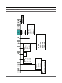
8. BLOCK DIAGRAM...................................................................................................................................8-1
9. WIRING DIAGRAM..................................................................................................................................9-1
9-1. WIRING DIAGRAM..............................................................................................................................................9-1
9-2. REFERENCE INFORMATION.............................................................................................................................9-2
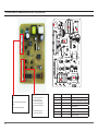
10. PCB DIAGRAM....................................................................................................................................10-1
10-1. PCB LAYOUT...................................................................................................................................................10-1
10-2. CONNECTOR & RELAY TERMINALS DESCRIPTION (MAIN PBA)...............................................................10-2
10-3. CONNECTOR & RELAY TERMINALS DESCRIPTION (SUB PBA)................................................................10-3
10-4. SUB PCB LAYOUT (THE PRINCIPLE PART)..................................................................................................10-4
10-5. MEMS PBA CONNECTOR TERMINAL DESCRIPTION & LAYOUT (THE PRINCIPLE PART).......................10-5
10-6. AG PBA CONNECTOR TERMINAL DESCRIPTION & LAYOUT (THE PRINCIPLE PART)............................10-6
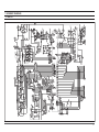
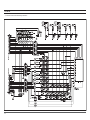
11. SCHEMATIC-DIAGRAMS .................................................................................................................. 11-1
11-1. MAIN PCB........................................................................................................................................................11-1
11-2. SUB PCB..........................................................................................................................................................11-2
11-3. MEMS PCB.......................................................................................................................................................11-3
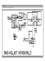
11-4. AG PCB............................................................................................................................................................11-4
12. REFERENCE INFORMATION
12-1. OVERALL SYSTEM.........................................................................................................................................12-1
12-2. POWER SUPPLY PART...................................................................................................................................12-2
12-3. DRIVING PART................................................................................................................................................12-3
12-4. SENSING PART...............................................................................................................................................12-4
12-5. COMMUNICATION PART................................................................................................................................12-5
13. REFERENCE INFORMATION
13-1. MODEL NAME.................................................................................................................................................13-1
13-2. TERMINOLOGY...............................................................................................................................................13-2
13-3. FABRIC CARE CHART....................................................................................................................................13-3
13-4. ELECTRICAL WARNINGS...............................................................................................................................13-4
13-5. Q & A................................................................................................................................................................13-5
1. PRECAUTIONS
1-1. SAFETY PRECAUTIONS
1.Do not allow the customer to repair the product.
☞ It may cause personal injury or product damage when the unit is serviced by unqualified personnel.
2.Disconnect power to the appliance before servicing.
☞ Be aware of the possibilities of an electric shock.
3.Do not use multi-plug.
☞ Power outlet may be overloaded causing the socket to overheat.
4.Check for any damage on power plug or power outlet.
☞ Replace it immediately if it has problem. (It may cause an electric shock or fire)
5.Make sure to earth the product.
☞ May cause electric shock.
6.Do not clean the product with water.
☞ May cause electric shock / fire or shorten product life.
7.The wiring harness should be free from moisture and connected properly during serving.
☞ It should be proof against any external force.
8.Remove any dust or dirt in the product, wiring section and connections during servicing.
☞ Protect against possibilities of fire due to tracking etc.
9.Check for any water trace on electrical parts, harness, etc.
☞ Replace the parts and /or wipe dry the water.
10.Check the assembled status of the parts after servicing.
☞ Check if the product is assembled in the same status as before servicing.
11.Be sure not to pull on the power cord but to unplug it by holding the plug.
☞ Beware of possibility of electric shock or fire when the power cord is damaged.
12.Unplug the power plug from the outlet when the washing machine is not used.
☞ Beware of possibility of electric shock or fire while lightening.
13.Do not use or put flammable materials (including gasoline, alcohol, thinner etc) around the washing machine.
☞ Flammable materials may spark an explosion or fire.
14.Do not put a water containing bowl or wet laundry on the washing machine.
☞ It may cause an electric shock or fire, or shorten the product life when its water penetrates into the washing machine.
15.Do not install the washing machine in a place where it is exposed to snow or rain etc.
☞ It may cause an electric shock or fire and shorten the product life.
16.Do not press control buttons with pointed objects such as pins, needles, etc.
☞ It may cause an electric shock or other problems.
17.Check the washing machine is leveled horizontally on the floor and is installed properly.
☞ Vibration may shorten the product life.
18.Make sure to use connectors when connecting wires.
☞ If wires are connected without connectors, it may cause a tracking fire.
19.When the washing machine is to be laid down for servicing, put a pad on the floor and lay the product on its side slowly.
☞ If the wash machine is laid on its front, internal components may be damaged by the tub.
1-1
1-2. PRECAUTIONS UPON INSTALLATION
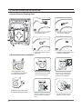
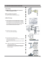
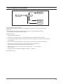
■ How to Remove Shipping Bolts
1. Remove the screws by using the supplied spanner.
3. Fill the holes with the supplied plastic caps.
■ Precautions before Installation
The unit is quite heavy.
So, make sure to have 2 or
more personnel move it.
Make sure that the unit stands
on a firm and leveled floor.
2. Remove the shipping bolts
from the back of the unit.
4. Keep the shipping bolts and screws for future use.
eep it away from direct sunlight
or high humidity, and install it in
a place with good ventilation.
Install the unit at a place with
a wall outlet easily accessible.
Keep the unit away from places in
which it is freezing, especially in
winter.
1-2
Keep the unit away from heat
appliances such as a heater.
1-2. PRECAUTIONS UPON INSTALLATION
■ Grounding
►Make sure to ground the unit to prevent electric leakage or shock.
With a grounded receptacle
►It does not need an additional grounding.
■Water Drainage
►Hook the drain hose over the Wash Basin or Laundry Tub or plug the end of the drai hose into the Standpipe
- Hook the drain hose over the Wash Basin or Laundry Tub or plug the end of the drain hose into the Standpipe
- The outlet end of the drain hose must be at least
60-90 cm above the base of the machine.
►Seal the drain pipe connections
- If not, it may cause water leakage.
►Prevent water from siphoning away
- If the end of the drain hose is put in water, it could siphon away water during washing.
So, make sure that the end of the drain hose is not put in water.
Note: Caution must always be exercised to avoid collapsing
or damaging the drain hose.
For best performance the drain hose should not be restricted in any way, through elbows, couplings or excessive lengths.
1-3
1-2. PRECAUTIONS UPON INSTALLATION
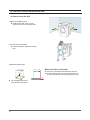
■ How to Level the Unit
1.Select an installation place.
►Install the unit with 10cm or more
clearance from its surrounding walls.
2.Check if the unit is leveled.
►If the unit wabbles, adjust the leveling
legs.
3.Adjust the leveling legs.
When the unit is not leveled
►Lift up the unit a little bit and adjust the shortest.
►Turn the leveling bolt counter clockwise as shown in the picture above (The leveling leg gets longer.)
► The 4 leveling legs should touch the floor all together.
1-4
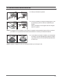
1-2. PRECAUTIONS UPON INSTALLATION
► Slide your Washer into position.
► Level your Washer by turning the leveling legs in or out
as necessary by hand or wrench included with your
Washer.
When your Washer is level, tighten the nuts using the wrench or (-)driver.
NOTE: Your Washer must be leveled on all four sides. A carpenter’s level should be used on all four corners of
your Washer. It’s a good idea after the first dozen washes to recheck your Washer’s levelness.
► If you install your washer on softfloor, you should place
the rubber cup under adjustable leg. Before put rubber
cup, please remove film for double-side tape attached
on rubber cup.
NOTE: If washer is installed on riser, you should put rubber cup under leg for riser.
1-5
Memo
1-6
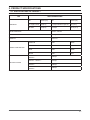
2. PRODUCT SPECIFICATIONS
2-1. SPECIFICATIONS OF PRODUCT
TYPE
DIMENSION
FRONT LOADING WASHER
Div
Inches (cm)
Div
Inches (cm)
A. Height-Overall
38 (96.5)
C. Depth With Door Open 90°
49 (124.5)
B. Width
27 (68.6)
D. Depth
30.25 (77.0)
WATER PRESSURE
50 kPa ~ 800 kPa
WEIGHT
89.9 kg
CAPACITY
3.29 Cu.ft
WASHING
120V
226W
WASHING AND HEATING
120V
997W
SPIN
120V
379W
DRAIN
120V
41W
WF326***
1200rpm
WF316*** / WF317***
1100rpm
WF306***
1000rpm
WF206***
1000rpm
POWER CONSUMPTION
SPIN REVOLUTION
2-1
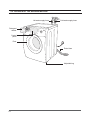
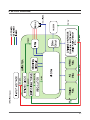
2-2. OVERVIEW OF THE WASHING MACHINE
Hot water supply hose
Cold water supply hose
Detergent
drawer
Control
panel
Door
Drain Hose
Adjustable leg
2-2
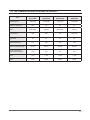
2-3. THE COMPARATIVE SPECIFICATIONS OF PRODUCT
Samsung
(WF316LAW)
Whirlpool
(GHW9250M)
LG
(WM2432HW)
Bosch
(WFMC6400)
3.29 (DOE)
3.21 (DOE)
3.22 (3.72)
2.93 (DOE)
93.4
90
91
83
Direct Drive
3-Phase
Direct Drive
3-Phase
LED
LED
LED
LCD (red)
57
52
59
66
1.01
1.00
0.99
1.02
48 Liter
56 Liter
49 Liter
61 Liter
128
105
114
189
RPM
1,100
1,100
1,200
1,200
Noise
57 dB
59 dB
66 dB
62 dB
Item
Capacity (Cu.ft)
Volume of Spinner (ℓ)
Motor
User Interface
Cycle Time
Wash Performance
Water Consumption/Cycle
Energy Consumption
(W/O Heater Wh/Cycle)
2-3
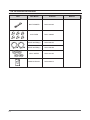
2-4. OPTION SPECIFICATIONS
Item
2-4
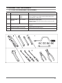
Item Name
Code No.
BOLT-SPANER
DC60-40146A
CAP-FIXER
DC61-10688A
HOSE-WATER(H)
DC62-00075A
HOSE-WATER(C)
DC62-00075B
SEAL-WATER
DC62-40178A
MANUAL-BOOK
DC68-02291A
Remark
3. OPERRATING INSTALLATION
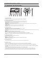
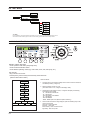
3-1. OVERVIEW OF THE CONTROL PANEL
1. Digital graphic display
Displays the remaining wash time, all wash information, and error messages.
2.
Temperature selection button
Press the button repeatedly to cycle through the different water temperature options.
Extra Hot/Cold - Heavily soiled, colorfast items. Only available with the Sanitize cycle.
Hot/Cold - Whites and heavily soiled, colorfast items.
Warm/Warm - Colorfast items. When warm rinse is selected, only the final rinse will be warm. The other rinses will be cold to conserve energy.
Warm/Cold - Moderately soiled, colorfast items; most wrinkle-free items.
Cold/Cold - Brightly colored, very lightly soiled items; washable woolens.
3.
Spin selection button
Press the button repeatedly to cycle through the different spin speed options.
Extra High - Removes more water from loads during spin.
NOTE: To minimize wrinkling of wrinkle-free and no-iron fabrics, DO NOT use the Extra High spin option for these loads, nor overload your Washer.
High - Use for underwear, t-shirts, jeans and sturdy cottons.
Medium - Use for jeans, wrinkle-free or wash-and-wear items and synthetics.
Low - Use for delicate items needing a slow spin speed because of fabric and construction.
No Spin - Drains your Washer without spinning. Use for extremely delicate items that cannot tolerate any spin.
4.
Soil Level selection button
Press the button to select the Soil Level/washing time.
Heavy - For heavily soiled loads.
Normal - For moderately soiled loads. This setting will be appropriate for most loads.
Light - For lightly soiled loads.
5. Signal selection button
Press the button to increase or decrease the end of cycle signal volume or turn off the signal.
6. SilverCare™ button
Silver ions are added during the wash and rinse cycles to maximize the sanitizing and antibiotic
effects, Harnesses pure silver’s sanitizing power and the state-of-the-art technological competency of SAMSUNG.
Two plates of 99.9% pure silver are converted into silver ions through electrolysis and penetrate into the laundry blended with water.
Even in cold water, silver particles sanitize and kill 99.9% of odor-causing bacteria.
Washing garments with SilverCareTM can save about 92% of energy compared to hot water sanitization. Also, SilverCareTM Technology significantly reduces damage to delicate clothes compared to sanitizing in hot water.
3-1
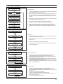
3-1. OVERVIEW OF THE CONTROL PANEL
7.
Select Cycle Option
Delay Start - Any cycle can be delayed for up to 12, 19 or 24hours (select models) in one-hour increments. Displayed hour indicates the time at which the wash will be finished.
Extra Wash - Add additional time to the wash for better stain removal.
Extra Rinse - Add an additional rinse at the end of the cycle to more thoroughly remove laundry additives and perfumes.
Extra Spin - Add additional time to remove more water from loads
My Cycle - Choose your favorite cycle including temperature, spin, soil level, option, etc.
Pre Wash - Add detergent to the Pre Wash selection of the detergent compartment. Washer fills with cold water and detergent, tumbles, then drains and advances to the selected wash cycle. Some cycles cannot be selected with this option.*
8.
Cycle Selector
Select the appropriate cycle for the type of load.
This will determine the tumble pattern and spin speed for the cycle.
NOTE: To minimize wrinkling of loads, select the Perm Press cycle.
Heavy Duty - For sturdy, colorfast fabrics and heavily soiled garments.
Normal - For most fabrics including cottons, linens, and normally soiled garments.
Whites - For white fabrics with or without bleach.
Perm Press - For wash-and-wear, synthetic fabrics, and lightly to normally soiled garments.
Delicates/Hand Wash - For sheer fabrics, bras, lingerie silk, and other handwash-only fabrics. For best results, use liquid detergent.
Wool - For machine-washable wool. Loads should be under 8 pounds.
* You can`t select PreWash option in Delicate/Hand Wash, Wool, Quick Wash and Active Wear cycles.
The wool wash cycle of this machine has been approved by Woolmark for the washing of machine washable Woolmark products provided that the products are washed according to the instructions on the garment label and those issued by the manufacturer of this washing machine, M0509.
Quick Wash - For lightly soiled or wrinkled garments needed quickly.
Towels - For bath towels and washcloths. Do not load too many towels because they absorb lots of water.
Sanitize - For heavily soiled, colorfast garments. This cycle heats the water to 150°F to eliminate bacteria.
NOTE: If Pause is selected during the heating portion of the Sanitize Cycle, your Washer door will remain locked for your safety.
Bedding - For bulky items such as blankets and sheets.
Active Wear - For washable sportswear.
Eco Wash - For geographic areas where energy and water conservation is needed.
Rinse + Spin - Use for loads that need rinsing only or to add rinse-added fabric softener to a load.
Spin Only - Provides a spin to remove more water from the load.
9. Start/Pause selection button
Press to pause and restart programs.
10.Power button
Press once to turn your Washer on, press again to turn your Washer off. If your Washer is left on for more than 10 minutes without any buttons being touched, the power automatically turns off. NOTE : Cycles and options vary by model. See next pages.
3-2
3-3
3-2. PROGRAMME CHART
3-4
3-2. PROGRAMME CHART
3-5
3-3. MAIN FUNCTION
CHILD LOCK
A function that prevents children from playing with your Washer.
ACTIVATING/DEACTIVATING
If you want to activate/deactivate the Child Lock function, press the Soil Level and Signal buttons at the
same time for 3 seconds.
How It Works:
1. Child Lock can be activated while your Washer is running.
2. Once you activate Child Lock, all controls (except for the Power button) will be locked until you
deactivate Child Lock.
3. The Child Lock button will be lit while it is in effect.
Note:
When buttons, other than the Power button, do not respond, please check if the Child Lock
button is on.
GARMENT +
You can add or take out laundry items even after the wash has started, as long as the Garment+ light is
on. Pushing the Start/Pause button unlocks the door, unless the water is too hot or if there is too much
water in your Washer. If you are able to unlock the door and wish to continue the wash cycle, close the
door and press the Start/Pause button.
MY CYCLE
Allows you to activate your custom wash (temperature, spin, soil level, etc.) with one-button
convenience.
By pushing the My Cycle button, you activate the settings used during the last My Cycle mode. The My
Cycle light will indicate activation.
You can select all options as follows in My Cycle mode.
1. Select cycle using Cycle Selector dial.
2. After cycle selection, set each option.
Note: At this time, the option will follow as per each cycle’s default option selection.
3. Then, you can start My Cycle by pushing the Start/Pause button in My Cycle mode.
The cycle and options you select will be displayed next time you choose My Cycle.
Note: You can change My Cycle setting by repeating same process above.
The last used setting will be displayed at next time you choose My Cycle.
3-6
3-3. MAIN FUNCTION
FOR SilverCare™ WASHING
An increased consumer demand for energy-saving products prompted Samsung to develop a system to
use silver, widely known for its antibacterial properties, in your washing machine. Pure silver atoms have
an electron stripped away by electrolysis during the wash and rinse cycles, which releases up to 400
billion silver ions that then penetrate deep into the fabric to sanitize clothing (according to U.S. EPA Test
Guideline DIS/TSS-13) without the need for hot water or bleach.
Here’s how it works: A grapefruit-sized device alongside the tub uses two pure silver plates the size of
large chewing gum sticks. The resulting positively charged silver atoms - Silver ions (Ag+) -- are sprayed
into the tub during the wash cycle. The ionic solution penetrates laundry and coats the individual fibers
with the ions. According to NSF tests, this process removed or killed greater than 99.9% of tested bacteria
(specified test bacteria in U.S. EPA Test Guideline DIS/TSS-13)
Samsung’s SilverCare™ Technology provides a 92% energy savings over hot water sanitization. Extra
delicate blouses, shirts, or even lingerie that can’t be washed in hot water can now be sanitized
effectively without the adverse effects of hot water washing that is normally a concern with those
types of articles. The silver plates carry a warranty of ten years, and can easily be replaced by a Service
Technician if so needed.
1. Open the door, put in the clothes and close the door again.
2. Press the Power button.
3. Select a Cycle by turning the Cycle Selection dial.
4. Press SilverCare™ button.
5. Add detergent in the dispenser tray for main washing, and add fabric softener up to the marked line.
: For Pre Wash, put a supplementary detergent in the dispenser.
SilverCare™ : If it is used together with fabric softener, its effect may be decreased.
6. Press Start/Pause button.
: Automatically selects optimal washing conditions by sensing the laundry’s weight.
Note :
FOR HOME USE ONLY– COMMERCIAL USERS SHOULD NOTIFY THEIR LOCAL WASTE TREATMENT
AUTHORITIES BEFORE USE
You can find # of times you used SilverCare™ option by pushing signal and SilverCare™ button.
LU3 : less than 1000 times
LU2 : between 1000 to 2000 times
LU1 : between 2000 to 2999 times
LU0 : over 2999 times
You should replace the SilverCare™ kit when it displays “LU0”. Contact 1-800-SAMSUNG.
Note :
For some model which has no heater if you choose SilverCare™, Temp will be fixed to Cold/Cold.
If you change Temp selection, the SilverCare™ option will be canceled.
You can’t choose SilverCareTM option with Wool cycle.
3-7
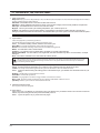
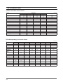
3-4. TECHNICAL POINT
1) Motor on/off time at each course
unit:sec
Course
Washing
Off
6
Ccw
14
Off
6
Motor r.p.m
Heavy Duty
Cw
14
Normal
14
6
14
6
45
Whites
12
8
12
8
45
Perm Press
5
5
5
5
45
Delicate/Hand wash
2
13
2
13
45
Wool
1
59
1
59
40
Quick Wash
12
8
12
8
45
Towels
10
10
10
10
45
Sanitary
10
10
10
10
45
Bedding
12
8
12
8
45
Active Wear
10
10
10
10
45
Eco Wash
12
8
12
8
45
Rinse + Spin
10
10
10
10
45
Spin Only
-
-
-
-
-
45
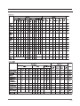
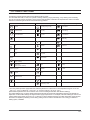
2) Final dehydrating r.p.m at each course
unit:rpm
Model
Course
Heavy Duty
WF326L
Default
MAX RPM
1200
1200
WF316L
Default
MAX RPM
1100
1100
WF306L
Default
MAX RPM
1000
1000
WF206L
Default
MAX RPM
1000
1000
Normal
1200
1000
1000
1100
1000
1000
1000
1000
Whites
1200
1200
1100
1100
1000
1000
1000
1000
Perm Press
Delicate/Hand
wash
Wool
800
1000
600
1000
600
600
600
600
800
400
400
400
400
400
-
-
400
600
600
600
600
600
-
-
Quick Wash
1200
1200
1000
1100
1000
1000
-
-
Towels
400
1200
1000
1100
1000
1000
1000
1000
Sanitary
1200
1200
1100
1100
-
-
-
-
Bedding
600
800
600
800
-
-
-
-
Active Wear
600
1000
-
-
-
-
-
-
Eco Wash
1000
1200
-
-
-
-
-
-
Rinse + Spin
1000
1200
1000
1100
1000
1000
1000
1000
Spin Only
1000
1200
1000
1100
1000
1000
1000
1000
3-8
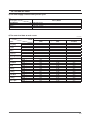
3-4. TECHNICAL POINT
3) The water supply control at each process cycle
Model
WF316, WF306
Process cycle
Cold water 5L/min
Cold water 10L/min + (Hot water 10L/min)
Cold water 10L/min
Cold water 10L/min + Cold water 5L/min
Pre Washing
Washing
Rinse
Final rinse
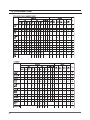
4) The water level data at each course
unit:Khz
Model
Course
Washing
Rinse
Washing
Normal
Rinse
Washing
Whites
Rinse
Washing
Perm Press
Rinse
Washing
Delicate/Hand wash
Rinse
Washing
Wool
Rinse
Washing
Quick Wash
Rinse
Washing
Towels
Rinse
Washing
Sanitary
Rinse
Washing
Bedding
Rinse
Washing
Active Wear
Rinse
Washing
Bedding
Rinse
Washing
Rinse + Spin
Rinse
Heavy Duty
Default water level
(kHz)
24.5
24.6
24.4
24.6
24.4
24.3
24.3
24.2
23.7
23.6
23.7
23.2
24.4
24.3
24.3
24.2
24.7
24.6
24.2
24.1
24.4
24.3
24.5
24.4
24.3
Water Level
Supplementary water START
(kHz)
24.85
24.95
24.75
24.6
24.75
24.65
24.65
24.55
24.05
23.95
24.75
24.65
24.65
24.55
25.05
24.95
24.55
24.45
24.75
24.65
24.85
24.75
24.65
Supplementary water
End (kHz)
24.6
24.7
24.5
24.95
24.5
24.4
24.4
24.3
23.8
23.7
24.5
24.4
24.4
23.3
24.8
24.7
24.3
24.8
24.7
24.4
24.6
24.5
24.4
3-9
Memo
3-10
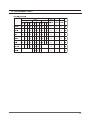
4. ALIGNMENT AND ADJUSTMENTS
4-1. GENERAL ERROR FUNCTION
LED
Diagnostic
NO Display
Code
Description
Corrective Action
1
nd
1
The water level fails to drop below the Reset Water Level
within 15 minutes.
2
LO
2
Door fails to unlock after 3 attempts.
3
nF
3
When the filling continues for more than 16 minutes or there
is no change of water level for 3 minutes
4
FL
4
Door fails to lock after 3 attempts.
5
LE
8
6
OE
E
7
dc
10
8
-
11
EEPROM Fault. (Program settings are being reset.)
9
E2
15
Jammed Key.(When key input signals are coming out for
more than 30 seconds, it is regarded as a jam.)
10
dL
18
Door is detected as open when the motor is operating.
11
dS
22
Door is detected as open while it is trying to lock the door.
12
bE
25
Motor hall sensor signals come out without motor operation.
Replace Machine Control Board.
13
tE
29
Abnormal high/low temperature or resistance (Thermal
sensor or PBA) resistance.
Go to “ Board Input Test” and check Water
Temperature. Check loose or pinched wires.
Replace PCB or thermistor.
Water Level Sensor Trouble.
(When the input signal from the water level sensor is out of
range, the unit will send out beeping sounds and halts the
cycle.)
A fault is detected in the water level sensor.
Data (frequency) shows the water level is at or above the
overflow water level. (When this condition is detected, the
machine will automatically starts draining water until the water
level falls below the overflow water level)
Unbalance or cabinet bump is detected during final spin,
which prevents the drum from spinning over 400 rpm. (Never
exceeds 400 RPM due to unbalanced load)
MICOM is attempting to drive the motor but is not getting any
response signals from the hall sensor. Visual check shows
motor is not running. (Locked, Defective Hall Sensor or
Overload)
System Relay (Main Relay) Failure. (PCB does not notice the
relay operation when there should be.)
Go to “ Will Not Drain” Troubleshooting
Section.
Go to “ Will Not Unlock” Troubleshooting
Section.
Go to “ No Water Fill” Troubleshooting
Section.
Go to “ Will Not Lock” Troubleshooting
Section.
Go to “No Water Fill” Troubleshooting Section.
First check to see that all of water valves are
not stuck. If water valves are OK, check water
level sensor.
Go to “Wet Clothes” Troubleshooting Section.
Go to “EEPROM Clear Mode” If display
shows “FAiL”,Replace Machine Control
Board.
Check all of keys. If A key is sensed to be
pressed, all keys will do not respond.
Check for loose wire connections.
Go to “Quick Test Mode” and then do Door
lock/Unlock Test and Motor Test.
Go to “Quick Test Mode” and then do Door
Lock/Unlock Test
Evaluate wire harness for loose or unhooked
connections. Go to “ Quick Test Mode” and
test Motor.
14
E3
2E
15
Sr
34
16
Hr
36
17
3E
3E
Over-current is detected. Motor won’t turn.
(IPM detects over-current.)
Evaluate wire harness for loose or unhooked
connections.
Go to “ Quick Test Mode” to test Motor.
18
2E
91
Voltage for motor control bus is over specified limit.
Replace PCB
19
2E
92
Voltage for motor control bus is under specified limit.
Replace PCB
20
8E
8E
MEMS Sensor Failure. (No MEMS Sensor Check Signal)
Check MEMS PCB ,Main PCB & Wireharness
21
7E
7E
Silver Care Kit (Silver Care PCB) Failure.
Check Silver Care PCB ,Main PCB & Wireharness
22
PF
-
23
SUdS
-
Heater Relay Failure (No Heater Relay Check Signal)
Replace PCB.
Replace PCB
It occurs when there is power failure during the washing.(“PF”
is not an error. It is to inform the user of power failure.)
Suds is detected during the washing session. (“SUdS” is not Guide a user to reduce amount of detergent
an error. If the washer is in suds period, “SUdS” will light up
usage.
instead of remaining time.)
4-1
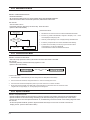
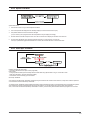
4-2. TEST MODE
7HVW0RGH
(DFK7HVW0RGHIRUWKH)URQWLHU:DVKHULVDVIROORZVLQWKHFRPLQJSDJHV7KHWHVWPRGHVLQGLFDWHGE\WKHUHG
DUURZVDUHWKHPRGHVXQDEOHWRJHWDQDFFHVVRQFHWKHZDVKLQJF\FOHKDVVWDUWHGGXHWRVDIHW\UHDVRQV
4-2-1. Quick Test Mode
Definition of Quick Test Mode:
- Check operation of all LED’s (Verify faulty LED).
- Check model and software version.
- Check different operating modes (e.g. water valve, motor, door, drain pump, etc.).
How to Enter:
- Plug in and turn on the unit.
- Press Spin Key, Soil Level Key and Power Key at the same time.
(Same for all Frontier models.)
Quick Test Mode:
4XLFN7HVW0RGH
1. All LED’s
light up and it sends out Beep Sound when it enters into the Quick Test Mode. (Including 7-Segment)
$OO/('¶VOLJKWXSDQGLWVHQGVRXW%HHS6RXQGZKHQLWHQWHUV
LQWRWKH4XLFN7HVW0RGH,QFOXGLQJ6HJPHQW
2. 3. Displays software version for a sec.
(Ex. If S/W Version is 60, 7-Segment will display U060)
'LVSOD\VVRIWZDUHYHUVLRQIRUDVHF
([,I6:9HUVLRQLV6HJPHQWZLOOGLVSOD\8
$IWHUGLVSOD\LQJWKHVRIWZDUHYHUVLRQ6HJPHQWZLOOGLVSOD\WKH
IROORZLQJLQIRUPDWLRQIRUHDFKPRGHO
):)/$::)/$6
):)/$:
)E:)%$&:)%$:
):)/$:
)E:)%+:
((((0RGHORSWLRQ(UURU1HHGWRUHSODFH3&%$VV\
After displaying the software version, 7-Segment will display the following information for each model.
- F1 : WF326LAW, WF326LAS
- F2 : WF316LAW
- F2b: WF316BAC, WF316BAW
:KHQPRGHOLQIRUPDWLRQLVEHLQJGLVSOD\HG
SUHVVWKHIROORZLQJNH\VWRWHVWYDULRXVFRPSRQHQWV
- F3 : WF306LAW
7HPS.H\:DWHU9DOYH7HVW
6SLQ.H\0RWRU7HVW
- F8b: WF306BHW
6RLO/HYHO.H\'RRU/RFN8QORFN7HVW
- EEEE : Model option Error (Need to replace PCB Assy.)
6LJQDO.H\'UDLQ3XPS7HVW
4. When model information is being displayed, press the following keys to test various components.
- Temp Key : Water Valve Test
- Spin Key : Motor Test
- Soil Level Key : Door Lock/Unlock Test
- Signal Key : Drain Pump Test.
4-2
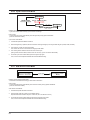
4-2-1. Quick Test Mode
:DWHU9DOYH7HVW
Water Valve Test:
7RHQWHUWKH:DWHU9DOYH7HVWSUHVVWKH7HPS.H\ZKLOH
1.PRGHOLQIRUPDWLRQLVEHLQJGLVSOD\HGGXULQJWKH4XLFN
To enter the Water Valve Test, press the Temp
7HVW0RGH
being displayed during the Quick Test Mode.
Key while model information is (DFKWLPHWKH7HPS.H\LVSUHVVHGLWZLOOF\FOHWKURXJK
WKHRSHUDWLRQVRQWKHOHIWIORZFKDUW
2.%XW:)/$:)DQG:)%+:)EGRQRWKDYH
Each time the Temp Key is pressed, it will cycle through the operations on the
WKHSUHZDWHUYDOYH6RLWZLOOVNLS3UH:DWHU9DOYH2QDQG
left flow chart. But, WF306LAW(F3) and WF306BHW(F8b) do not have the MXPSWR&ROG:DWHU9DOYH2Q
pre water valve. So, it will skip Pre Water Valve On and jump to Cold Water Valve On.
,IWKH7HPS.H\LVSUHVVHGGXULQJ$OO:DWHU9DOYH2))
WKHPDFKLQHZLOOUHWXUQWRWKHEHJLQQLQJDVVKRZQ
LQWKHIORZFKDUW
3. If the Temp Key is pressed during All Water Valve OFF, the machine will return to the beginning as shown in the flow chart.
7KHGRRUQHHGVWREHVHFXUHGIRUWKH:DWHU9DOYHWRRSHUDWH
7KHUHIRUHWKHGRRUORFNZLOOEHRQGXULQJWKHZDWHUYDOYH
RSHUDWLRQ
4. The door needs to be secured for the Water Valve to operate.
Therefore, the door lock will be on during the water valve operation.
,IWKHUHLVDQ\SUREOHPZLWK:DWHU9DOYH3&%$VV\RU:LUH
+DUQHVVWKHZDWHUYDOYHVFRXOGQRWRSHUDWH6RWRPDNHVXUH
IRUWKHZDWHUYDOYHVWRRSHUDWHFKHFNYLVXDOO\LIZDWHUFRPHV
5.RXWZLWKHDFK:DWHU9DOYH2QPRGH
If there is any problem with Water Valve, PCB Assy. or Wire Harness,
the water valves could not operate. So, to make sure for the water valves to operate, check visually if water comes out with each Water Valve On mode.
Motor Test:
1. To enter the Motor Test, press the Spin Key while model information is being displayed during the Quick Test Mode.
2. Each time the Spin Key is pressed, it will cycle through the operations on the left flow chart.
4. The Door Lock will be on during the motor operation.
5. If there is any problem with Motor, PCB Assy. or Wire Harness,related error codes will be displayed.
Door Lock/Unlock Test:
1. 2. 3. 4. To check the Door Lock/Unlock operation, press the Soil Level Key while model information is being displayed during the Quick Test Mode.
Each time the Soil Level Key is pressed, it will cycle through the Door Lock/
Unlock operations on the left flow chart.
If the Soil Level Key is pressed during Door Lock and Water Valve, Motor or Drain Pump operation, all of the operations will stop. And, when the Soil Level Key is pressed again,the door will be released.
If there is any problem with Door Switch, PCB Assy. or Wire Harness, related error codes will be displayed.
Drain Pump Test:
1. 2. 3. 4. To check the Drain Pump operation, press the Signal Key while model information is being displayed during the Quick Test Mode.
Each time the Signal Key is pressed, it will cycle through the operations on the left flow chart.
The Drain Pump operation is independent.
Therefore, it will operate regardless of Door Lock/Unlock.
If there is any problem with Drain Pump, PCB Assy. or Wire Harness, the Drain Pump will not operate.
So, its operation needs a visual inspection.
4-3
4-2-2. EEPROM Reset Mode
Definition of EEPROM Reset Mode:
- EEPROM initialization.
- All course/option settings are to be reset to default values after EEPROM initialization.
- When Service arises and it needs PCB replacement, EEPROM should be reset.
How to Enter:
- The unit needs to be on.
- Press Delay Start Key, Signal Key and Power Key at the same time.
(Same for all Frontier models.)
EEPROM Reset Mode:
1. EEPROM can be reset once the user enters the EEPROM Clear Mode.
2. If there is any problem with EEPROM, 7-Segment will display “ FAiL ”. “Good” will be displayed if everything is OK.
3. PCB assy. needs replacing if “FAiL” is displayed during EEPROM reset.
4. If PCB assy. is replaced for some reason, EEPROM needs resetting.
5. If problem occurs with Sticky Function, My Cycle and Power Failure Compensation, it may be due to EEPROM .
Check EEPROM’s condition at EEPROM Clear Mode.
4-2-3. Continuous Run Mode
Definition of Continuous Run Mode:
- Will continuously repeat the current cycle until the Continuous Run Mode is cancelled.
How to Enter:
- Press Delay Start Key and Extra Rinse Key together for 3 sec.
(Same for all Frontier models.)
Continuous Run Mode:
1. Press Delay Start + Extra Rinse Key for 3 sec during Power On State (Normal User Mode) .
2. Once in Continuous Run Mode, 7-Segment will blink “cc” and the remaining time in turns.
3. The Continuous Run Mode will repeat the previous cycle until continuous run mode is cancelled.
4. During Continuous Run Mode, press Delay Start + Extra Rinse Key for 3 seconds to return to normal user mode.
7-segment will no longer display “cc”, but only display the remaining time.
4-2-4. Special Test Mode
Definition of Special Test Mode:
- Special Test Mode enables service technicians to verify the operation of the washing machine and do troubleshooting.
- Special Test Mode can be entered during all washing cycle without interrupting the cycle except some of test modes.
- Various tests can be done with Special Test Mode. So, troubleshooting can be done based on the resulting diagnostic codes.
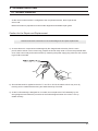
How to Enter:
- To enter the Special Test Mode, press the Signal and Extra Rinse Keys for 3 seconds or until the unit sends out
beeping sounds. (same for all Frontier models.)
4-4
4-2-4. Special Test Mode
Special Test Mode:
1. The washer must be on to go into the Special Test Mode.
2. The motor speed will be displayed when started (It displays 0 when the motor does not spin).
3. The present state of the machine will not be changed.
(i.e., the current cycle in progress will not be interrupted and only the display will change)
4. All LED’s will be turned off except the “Door Lock” LED. It will continue to display the condition of the door lock.
5. To exit Special Test Mode, press Signal and Extra Rinse Keys for 3 second again, or Power Key.
If no key is operated during Special Test Mode for 5 minutes, the machine will return to normal user mode.
4-2-5. Quick Spin Test Mode
Definition of Quick Spin Test Mode:
- Quick Spin Test Mode is to do Spin Check. (High RPM)
How to Enter:
- During Special Test Mode, press the Delay Start and Silver Wash Keys (Rinse Water + Key) for 3 seconds to enter
Quick Spin Test Mode. (same for all Frontier models.)
- Cannot enter once the washing cycle has started.
Quick Spin Test Mode:
As it enters into the Quick Spin Test Mode, it starts spinning and reaches to its maximum RPM. And then, it stays at its maximum speed for
2 minutes before it exits the Quick Spin Test Mode.
To hold Quick Spin Test Mode (entering Speed Hold Mode), press the Start/Pause button. If the Start/Pause button is pressed during Quick
Spin Test Mode, it will stop accelerating and hold its spinning speed for 10 minutes before going back to Quick Spin Test Mode.
Also, to cancel the hold and allow Quick Spin Test Mode to continue, press the Delay Start and Silver Wash Keys together for 3 seconds.
4-5
4-2-6. Cycle Count Check Mode
Definition of Cycle Count Check Mode:
- Cycle Count Check Mode is to tally up the number of washings.
How to Enter:
- To enter the Cycle Count Check Mode, press the Signal Key during Special Test Mode.
(same for all Frontier models.)
Cycle Count Check Mode:
1. Activate the Special Test Mode in advance.
2. When the Signal key is pressed, the total number of washings will light up and a signal LED will glow (Louder, Softer, Off LED).
3. The maximum number of cycles will be 2999.
The counter will roll over to 0 and start counting again after 2999.
4. The counting will be carried out at the end of the normal cycle.
(During Continuous Run Mode, it does not Do not count any cycle in Continuous Run Mode)
5. To exit the Cycle Count Check Mode, press the “Signal” key again.
Then, it returns to the Special Test Mode with motor RPM illuminating.
4-2-7. S/W Version Check Mode
Definition of S/W Version Check Mode:
- S/W Version Check Mode is to bring up S/W Version information.
How to Enter:
- To enter the S/W Version Check Mode, press the Soil Level Key during Special Test Mode.
(same for all Frontier models.)
S/W Version Check Mode:
1. Activate the Special Test Mode in advance.
2. Press the Soil Level Key to bring up its software Version
EX) Generate F005 at Version 05 (F0 is model code, 05 is it’s software version)
3. To exit the S/W Version Check Mode, press the Soil Level S/W once again.
Then, it returns to the Special Test Mode with motor RPM illuminating.
4-6
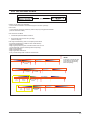
4-2-8. Fast Time Down Test Mode
Definition of Fast Time Down Test Mode:
- Fast Time Down Test Mode is to forward the program to the next cycle stage.
How to Enter:
- To enter the Fast Time Down Test Mode, press the Temp key during Special Test Mode.
(same for all Frontier models.)
Fast Time Down Test Mode:
1. Activate the Special Test Mode in advance.
2. To forward the program to the next cycle stage,
press the Temp key.
Each stage is located at key points of a complete cycle as follows:
- End of Each Fill (Beginning of Wash or Rinse Tumble Session)
- Beginning of Drain Session
- Beginning of Spin Session (Here, it checks the water level. So, if it is
over the reset level, it carries out draining before the spinning.)
- Beginning of Fill Session
- Beginning of Bleach Fill
- Beginning of Fabric Softener Fill
- Every 3 minutes during Wash and Rinse Tumble Session
0DUNHU
mG~
wG~
k
$WWKLVSRLQWLWFKHFNVWKHZDWHU
OHYHODQG,ILWLVRYHUWKHUHVHW
OHYHOLWZLOOFDUU\RXWGUDLQLQJ
EHIRUHWKHVSLQQLQJ
z
PLQXWHV
mG~
tG~
PLQXWHV
mG~
w
}
k
z
PLQXWHV
mG~
w
}
z
PLQXWHV
y
iG
z k
zG
z mGy
k
mGz
PLQXWHV
4-7
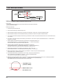
4-2-9. Board Input Test Mode
Definition of Board Input Test Mode:
- Board Input Test Mode is to displays a specified input after a key press.
How to Enter:
- To enter the Board Input Test Mode, press the Extra Wash key during Special Test Mode.
(same for all Frontier models.)
Board Input Test Mode:
1. Activate the Special Test Mode first.
2. Press the Extra Wash key to start Board Input Test.
3. Water Temperature Display in Celsius Dial the Rotary Cycle Selector to “Heavy Duty” and press the Start/Pause dial.
4. Water Temperature Display in Fahrenheit Dial the Rotary Cycle Selector to “Normal” and press the Start/Pause dial.
5. Door Position (Open/Close) Display Dial the Rotary Cycle Selector to “Whites” and press the Start/Pause dial: “OP” will illuminate if open, “CL” if closed.
6. Door Status (Lock/Unlock) Display Dial the Rotary Cycle Selector to “Perm Press” and press the Start/Pause dial: “UL” will illuminate if unlocked, “LO” if locked.
7. Overflow Water Level Display Dial the Rotary Cycle Selector to “Delicate/Hand Wash” and
press the Start/Pause dial: “ ‾0 ” will illuminate if below level, “ ‾1 ” if above level (Overflow).
The above water level is defined as the overflow water level.
8. Heater-On Water Level Display Dial the Rotary Cycle Selector to “Wool” and
press the Start/Pause dial: “ -0” will illuminate if below level, “-1” if above level (Heater-On).
The Medium water level is defined as the level needed for the heater to turn on.
9. Reset Water Level Display Dial the Rotary Cycle Selector to “Quick Wash” and
press the Start/Pause dial: “_0” will illuminate if below level (Reset), “_1” if above level.
10. Water Level Display (Frequency) Dial the Rotary Cycle Selector to “Towels” and press the Start/Pause dial:
If it illuminates “2435”, it indicates 24.35 kHz.
11. AG Kit Status Dial the Rotary Cycle Selector to “Rinse+Spin” and press the Start/Pause dial.
Then, it will display the Ag Kit Status in 3 seconds: “- -” if AG kit is operated properly.
“7E” if AG kit is out of order (check wire harness & PCB)
12. MEMS Sensor Kit Status. Dial the Rotary Cycle Selector to “Spin Only” and press the Start/Pause dial. Then, it will display the MEMS Sensor Kit status after displaying “00” for 3 seconds: “- -” if MEMS Sensor kit is operated properly.
“8E” if MEMS Sensor kit is out of order (check wire harness & PCB)
+LJK:DWHU/HYHO
2YHUIORZ/(9(/
0HGLXP:DWHU/HYHO
+HDWHU
4-8
5HVHW:DWHU/HYHO
4-2-10. Diagnostic Code Check Mode
Definition of Diagnostic Code Check Mode:
- Diagnostic Code Check Mode is to bring up the stored diagnostic codes (reference codes for service technicians).
How to Enter:
- To enter the Diagnostic Code Check Mode with code “d” flashing, press the Silver Wash (Rinse Water +)
during Special Test Mode. (same for all Frontier models.)
Board Input Test Mode:
1. Activate the Special Test Mode first.
2. Press the “Silver Wash (Rinse Water +)” key to start Diagnostic Code Check Mode with Code “d” flashing.
3. To cycle through the diagnostic codes (d1,d2,d3~d9), turn the Rotary Cycle Selector in one direction (either Clockwise or Counterclockwise).
4. Now, when turning the Rotary Selector Key in the same direction, it shows diagnostic codes from the latest (d1).
5. When turning it in the opposite direction, it shows the diagnostic codes in the reverse order.
Ex) When it stops at d5 and turns backward, it shows from d4 down to “d”.
6. EEPROM holds the codes up to 9 of them. So, when it goes beyond it, “- -” and “d” will light up.
Ex) “d” – d1~d9 – “- -”
7. When there are only 6 codes stored in EEPROM, it will display “- -” after them.
Refer to Diagnostic Code.
4-9
Memo
4-10
5. ASSEMBLY AND DISASSEMBLY
5-1. TOOLS FOR DISASSEMBLY AND ASSEMBLY
NO.
TOOL
Box driver
10mm
13mm
19mm
Heater (1)
Motor (1), Balance (5), 2 holes of each left and right of the
shock absorber 1 Pulley hole
10, 13,19mm
2
Double-ended
spanner
Replaceable for the box driver.
Since the bolt runs idle when the box driver is used, use the
box driver 17mm.
3
Vice pliers
Tool to protect the idle and abrasion of the bolt for the
box driver.
4
Other(Driver, Nipper, Long nose)
General tools for the after service.
5
JIG for the Tub
1 (Disassemble and Assemble)
1
5-1
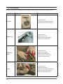
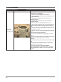
5-2. DISASSEMBLY
Warning! To avoid risk of electrical shock, personal injury or death, disconnect the power to the washing machine.
Part Name
Descriptive Picture
How To Do
Top Cover
1. Unplug the unit.
2. Remove screws(2ea) at the back.
3. Slide Top Cover back and lift it up.
MEMS Sensor
1. Unplug the unit.
2. Remove Top Cover.
3. Disconnect the wire harness.
4. Remove the screws(2ea)
Water Level
Sensor
1. Unplug the unit.
2. Remove Top Cover.
3. Remove the screw(1ea).
4. Disconnect the wire harness.
5. Take out Pressure Hose.
Ag Kit
1. Unplug the unit.
2. Remove Top Cover.
3. Remove screws(2ea) from the rail.
4. Disconnect the wire harness.
4. Remove clamps and hoses.
5-2
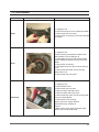
5-2. DISASSEMBLY
Part Name
Descriptive Picture
How To Do
Ag PCB
1. Unplug the unit.
2. Remove Top Cover.
3. Flip open the PCB cover.
4. Disconnect the wire harness.
5. Remove screws (2ea) on the frame.
EMI Filter
1. Unplug the unit.
2. Remove Top Cover.
3. Remove the earth screw.
3. Remove the acorn nut (13mm) and
disconnect the wire harness.
Water Valve
1. Unplug the unit.
2. Remove Top Cover.
3. Remove two screws for each Single Hot
and 3-Combo Cold Valve.
4. Remove clamps and hoses.
Dispenser
1. Unplug the unit.
2. Remove Top Cover.
3. Remove Dispenser Drawer.
4. Remove screws(3ea) on the top.
5. Plug out all the connectors.
6. Unscrew(6ea) PCB and separate it from
Console.
5-3
5-2. DISASSEMBLY
Part Name
Descriptive Picture
How To Do
Console
1. Unplug the unit.
2. Remove Top Cover.
3. Remove Dispenser Drawer.
4. Remove screws(3ea) on the top.
5. Plug out all the connectors.
6. Unscrew(6ea) PCB and separate
it from Console.
Door
1. Unplug the unit.
2. Remove screws(2ea) and takeout Door Assy
from Front Panel.
3. Remove screws along the
perimeter of Glass Retainer.
4. Remove Glass Retainer.
5. Remove Door Glass.
6. Remove Hinge.
7. Remove Outer Window Panel.
Front Panel
1. Unplug the unit.
2. Remove Top Cover, Dispenser, Console and
Door.
4. Snap up the boot at 6 o’clock and pull out
the clamp spring.
5. Pull the boot from the lip formed into the front
opening.
6. Remove screws(2ea) on the bottom.
7. Remove screws(4ea) on the top.
8. Plug out the connectors to Door Lock.
9. Lift out Front Panel.
Boot
1. Unplug the unit.
2. Knock the unit down to Front Panel
(included).
3. Unscrew the boot clamp at 12
o’clock.
4. Pull out the boot.
5-4
5-2. DISASSEMBLY
Part Name
Descriptive Picture
How To Do
Heater
1. Unplug the unit.
2. Knock the unit down to Front Panel (included).
3. Remove the wire connectors.
4. Remove the nut (10mm) in the center and take
out Heater.
Motor
1. Unplug the unit.
2. After removing screws(2ea) on Back Cover,
take out Back Cover by sliding it up.
4. Rotate Motor Cover to locate a slot in Stator.
Insert a Phillips screwdriver into the slot to lock
Stator.
5. Remove the nut (19mm).
6. Grab Motor Cover at 3 and 9 o’clock and pull
it out.
7. Remove the bolts (6ea, 10mm) securing
Stator Coil to Tub.
8. Remove the wire connectors.
Drain Pump
1. Unplug the unit.
2. Remove Back Cover.
3. Remove the wire connector.
4. Remove Clamp and Drain Hose.
5. Remove Clamp and Pump Hose.
6. Remove the bolts (3ea, 13mm) securing Drain
Pump to Cabinet Bottom.
7. Remove the screw securing
Drain Pump to the support bracket.
Twist Drain Pump clockwise to
remove.
* Make sure to put an empty container under
Drain Pump to hold water inside.
5-5
5-2. DISASSEMBLY
Part Name
Outer Tub
and Spinner(1)
5-6
Descriptive Picture
How To Do
1. After the above knock-down to
Drain Pump, do the following.
2. Remove screws holding the wire harness.
3. Remove the bolts (2ea,13mm) securing Rear Struts
to Cabinet Bottom.
4. Swing Struts up against Tub to make it easy to
remove Tub Assy.
5. Remove bolts (2ea each side, 13mm) securing
Counter Weights.
6. Remove the screw holding the wire harness.
7. Remove bolts (2ea each side, 13mm) securing Front
Struts to Cabinet Bottom and swing Struts up against
Tub..
8. Loop the wire harness and Water Pressure Hose out
of its retaining holders.
9. Remove screws (7ea) securing Rail Frame and take
it off.
10. Remove Clamp and Vent Hose.
11. Loop out Suspension Spring by lifting it up (each
side).
12. Take out Tub and put it on block supports (4” wood
blocks or their equivalents) to prevent shaft
damage.
13. Remove screws (10mm) around the perimeter of the
tub.
14. Separate Front and Back Tubs from each other.
15. Take out Spinner Drum.
16. Remove screws to disassemble Baffles.
* When assembling, make sure that Front and Back
Tubs are fastened up tightly. If not, it will cause water
leakage.
6. TROUBLE SHOOTING
6-1. TROUBLE DIAGNOSIS
- As the micom wash machine is configured of the complicate structure, there might be the
service call.
Below information is prepared for exact trouble diagnosis and suitable repair guide.
Caution for the Repair and Replacement
Please follow below instruction for the trouble diagnosis and parts replacement.
1) As some electronic components are damaged by the charged static electricity from the resin part of wash machine or the human body, prepare the human body earth or remove the potential differ
ence of the human body and wash machine by contacting the power supply plug when the work contact
ing to PCB is executed.
2) Since AC220~240V is applied to the triac T1 and T2 on P.C.B, the electric shock may occur by touching and be careful that the strong and weak electricity are mixed.
3) As the P.C.B assembly is designed for no trouble, do not replace the P.C.B assembly by the wrong diagnosis and follow the procedure of the trouble diagnosis when the micom is not op
erated normally.
6-1
6-1. TROUBLE DIAGNOSIS
WARNING
To avoid risk of electrical shock, personal injury or death, disconnect power to unit before servicing, unless testing requires
power.
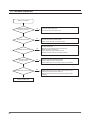
No Power
Is the voltage of the
outlet normal?
Is the Power Cord normal?
Is the Noise Filter normal?
Unplug the power cord and check the power of the outlet?
- Check the Circuit Bracket.
- Check for power disconnection and supply the rated power.
NO
Check the power cord and replace the power cord.
- Check whether there is any damage in the Plug.
- Check for disconnection and Short circuit in power cord.
NO
Is the button and
Sub PCB normal?
NO
Is the connected condition
of the Connector normal?
NO
Replace the Main PCB.
6-2
NO
Check and replace the noise filter if there is a problem.
- Check whether the housing of the input/output side is normally done.
- Check for disconnection and Short circuit in the Noise Filter.
- Remove the Cover Top and pull out the terminal of the output side.
Then connect the power and check the output voltage. (About AC120V)
(Always unplug the power after checking to prevent electric shock)
Check the power button and Sub PCB.
- Check the feeling and sense when operating the power button and
when it is locked or cannot be pressed, resolve the issue.
- When the S/W product is defective or the board damaged, replace the
Sub PCB.
- Check whether the Flat Wire connecting the Main and Sub has
deviated. (13P)
Check whether the connection condition of the Wire is the same as the
wiring diagram.
- Check the disconnection of the power supply by looking at the wiring
diagram.
- Check the Main PCB Fuse and replace the Main PCB when Opening.
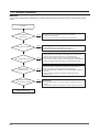
6-1. TROUBLE DIAGNOSIS
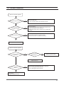
Will Not Start
Is the Start/Pause button pressed
after selecting the course?
Is the Door Lock S/W normal?
NO
Press the Start/Pause Key once.
- When the operation is unstable from locking or hitting, resolve the
issue and replace the necessary parts.
- When the Sub PCB Encoder S/W is defective, replace the Sub PCB.
NO
Check the Door Lock S/W.
- Check whether the Door causes an Error and if so, resolve the issue.
(door S/W terminal loose, part defective)
- Close the Door completely.
- When the Door Lock S/W is damaged, replace the parts.
Is the water supply
condition normal?
NO
Is the water drain
condition normal?
NO
Isn’t there any Error?
NO
Check the water supply part.
- Check whether the water supply Hoses for hot and cold water are
connected properly.
- Check whether the water is not disconnected. (“nF” Error)
- Check whether the water level sensor is normal. (“LE” Error)
Check the water drain part.
- Check whether the water drain is normal.
- Check whether there is water inside the drum.
Check whether there is any Error.
- In case of E3 and 3E Error, check the Motor and Hall Sensor part
and check the connected condition of the connector.
- Check the “LE” and “tE” water level sensor and temperature sensor.
- Check whether the “E2” button is pressed.
- Refer to other service Error and resolve the any issues.
Replace the Main PCB.
6-3
6-1. TROUBLE DIAGNOSIS
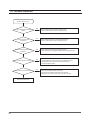
Leaking
<Plug the unit into the wall outlet>
Is there a leakage in the
water supply part?
Is there a leakage in the
water drain part?
NO
Is there a leakage in the
Housing drawer?
NO
Is there a leakage in the
Diaphragm?
NO
Is there a leakage in the
Front and Back of the Tub?
NO
Replace the Tub.
6-4
NO
Check the leakage of the water supply part.
- Check the connected condition between the water facet and water supply hose.
- Check the connected condition between the water supply hose and the Valve.
- Check the Water Valve.
- Check the connected condition between the Water Valve and Housing Drawer
Hose.
- Check the clogging due to Housing Drawer detergent.
- Check the connected condition between the Housing Drawer and Tub Hose.
Check the leakage of the water drain part.
- Check the leakage of Door Glass and Diaphragm.
- Check the connected condition of the Pressure Hose.
- Check the leakage of the connected part of the Front and Back of the Tub.
- Check the connected part of the Ventilation Hose. (Leakage during spin)
- Check the connected condition of the Drain Pump in the Tub.
Check the leakage of the Housing drawer.
- Check the connected part of the Drain Pump Hose.
- Check any break of Drain Hose.
- If the Housing drawer is damaged and replace it.
Check the Diaphragm.
- Check whether there is any fabric stuck on the Diaphragm.
- In case of leakage from permanent deformation of Diaphragm,
replace the part.
- When the Housing drawer is damaged, replace it.
Check the Front and Back of the Tub.
- Check whether the upper Ventilation Hose is pulled out.
- Check if there is any abrasion or missing Bolt in the Front and Back
assembly of the Tub.
6-1. TROUBLE DIAGNOSIS
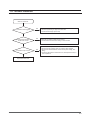
The drum is not rotating
Is the water supplied to the
set level and stopped?
Is there a “3E” Error on the Display?
Is the water drain normal?
Is the Motor operating normally?
Is the connected condition of
the Wire normal?
NO
NO
NO
NO
NO
Check the water level sensor part.
- Connect the terminal of the water level sensor firmly.
- Check the output frequency of the water level sensor.
(Frequency: 22Kz-26KHz) In case of defect, replace the part.
- Check whether there are any breaks on the Pressure Hose or
whether the pressure hose is pulled out, and take appropriate
measures.
Check the Motor part.
- Connect the Motor and Hall Sensor terminal firmly.
- Correct the Wire form. (2 Wire Holders)
- Check the Motor and Hall Sensor parts.
- Refer to the Wiring diagram and check for wire disconnection.
When the water level does not reach the Reset level (25.5Khz) during
draining, it will not proceed to the spin cycle. It generates an “nd”
Error after 15 minutes.
Check the water drain.
Check the Motor.
- Check the Wire color. (RED/WHT/BLU)
- Check the Motor resistance (RED<->BLU, RED<->WHT about 10Ω20Ω)
Check the connected condition of the Wire.
- Check the housing connected to the Main PCB.
- Check the Wire with the Motor with the tester.
- Check the Hall sensor Wire with the tester.
Replace the Main PCB
6-5
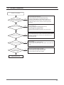
6-1. TROUBLE DIAGNOSIS
Water is not supplied
Is the water supply hose
connected normally?
Is the water facet open?
Is the Water Valve normal?
Is the connected condition of
the Wire normal?
Is the water level sensor normal?
Replace the Main PCB.
6-6
NO
NO
NO
Connect the water supply hose.
- Connect the hot and cold water hose.
Check the water facet valve.
- Connect the hot and cold water valves.
- Check whether the water is not disconnected.
Check the Water Valve.
- Remove any alien particles in the Valve Filter part.
- Check the Valve Coil resistance.
Check whether you hear a “Woong” sound.
- Replace the Value when you have other problems.
NO
Check the connected condition of the Wire.
- Check whether the Wire is disconnected.
- Check whether there is any housing missing or Pin deviated.
NO
Check the Pressure.
- Check whether there are any breaks on the pressure hose or
whether the Pressure Hose is pulled out.
- Replace the Pressure Sensor if there are any problems after
checking.
6-1. TROUBLE DIAGNOSIS
Water is continuously supplied.
Is the water supply valve normal?
Is the pressure Hose
connected normally?
Is the Wire connection normal?
NO
NO
NO
Check the Water Valve.
- It is from the alien particles inside. Replace the valve.
Check the Pressure.
- Check whether there are any breaks on the pressure hose or
whether the Pressure Hose is pulled out.
- Replace the Pressure Sensor if there are any problems after
checking.
Check whether the Wire is connected correctly.
- Check the connection of the Main PCB Housing.
Replace the Main PCB.
Water is continuously supplied.
Is the noise generated from inside
the drum?
NO
Are there any alien objects
inside the drum?
NO
Remove any alien objects.
It is from a drum assembly defect.
Replace the drum.
Is the noise generated from the
Motor?
NO
Noise from bolt or nut loosening from the connected part.
- Bolt from fixating Motor Stator loosened.
- Nut from fixating Motor Rotor loosened.
Noise from abrasion from contact with
motor bearing
- Replace the Back of the Tub.
6-7
6-1. TROUBLE DIAGNOSIS
The Door does not open.
Isn’t the washer filled with water
inside?
Is there hot water inside
the washer?
Did you unplug the power during
operation?
Is the Wire connection normal?
Is the Door Lock S/W normal?
Replace the Main PCB.
6-8
NO
NO
NO
NO
NO
Check whether there is any water inside the drum.
(There is a forced lock function for safety purpose.)
Check whether there is any hot water inside the drum.
(There is a forced lock function for safety purpose.)
Check whether the power was unplugged by force.
- When the power is unplugged, plug the power and open the door.
Check the connected condition of the Wire.
- Check whether the housing of the Door Lock S/W is missing.
- Check whether the housing Pin is pushed and missing.
- Check Wire disconnection.
Check the connected condition of the Wire.
- Check the coil resistance of the Door Lock S/W Coil.
Replace the parts when the part is Open or Short circuited.
6-1. TROUBLE DIAGNOSIS
Water is not drained.
Is the drain hose clogged?
Is the connected condition of
the terminal normal?
Is the drain Pump normal?
NO
NO
NO
Check the drain hose.
- Remove any bending or clogs in the drain hose.
- Check the drain height. (9 ft or less)
Check the connected condition of the terminal.
- Check whether the terminal is missing or disconnected.
Check the drain Pump.
- Remove the alien particles when it is locked by alien particles.
- Remove the overload element of the Protector (over voltage, time
delay)
- Check Coil disconnection and Short circuit, and replace the Pump in
case of problems.
Replace the Main PCB.
6-9
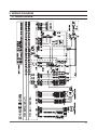
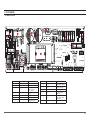
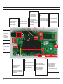
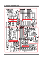
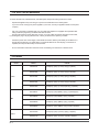
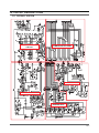
6-2. PROBLEM CHECKING AND METHOD OF PCB
-If you plug in the power cord and turn Power S/W on, memorized data is displayed.
If any data is not displayed, check the followings.
① CN1 ⑬
① CN2 ⑬
① CN4 ⑤
③ CN9 ①
③ CN9 ①
① CN8 ④
① CN3 ⑨
⑤
⑧
④
①
Check Voltage at Pin #6 and #3 of CN3
Tester Check = DC2.5V
If it reads 5V, check if its connector is engaged properly.
Door Switch Check
Check Voltage at Pin #6 and #4 of CN3
When Door Open = DC5V
When Door Close = DC0V
Check Voltage and Frequency at Pin #6 and #7 of CN3
Reset water level = DC2.5V, 25.8KHz
Check Voltage and Frequency at Pin #6 and #8 of CN3
Reset water level = DC2.5V, 25.8KHz
Sump Sensor Check
Check Voltage at Pin #4 and #2 of CN8
Tester Check = DC0V or 3.75V
Check Voltage at Pin #4 and #3 of CN8
Tester Check = DC0V or 3.75V
Motor Check
Resistance at Pin #1 and #2 of CN9 =11.6Ω
Resistance at Pin #1 and #3 of CN9 =11.6Ω
Resistance at Pin #2 and #3 of CN9 =11.6Ω
6-10
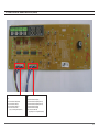
CN7
①
CN10
Thermistor Check
Water Sensor Check
②
① CN9 ②
Door Lock Check
Check Voltage at Pin #1 of CN5 and Pin #7 of CN10
When Door Lock = AC120V
Check Voltage at Pin #1 of CN5 and Pin #2 of CN7
When Door Lock = AC120V
Door Unlock Check
Check Voltage at Pin #1 of CN5 and Pin #8 of CN10
When Door Unlock = AC120V
Drain Motor Check
Check Voltage at Pin #1 of CN5 and Pin #6 of CN10
When Drain Pump operates = AC120V
Water Valve Check
Check Voltage at Pin #1 of CN5 and Pin #1,2,3,4 of CN10
When each Valve operates = AC120V
AC Power Check
Check Voltage at Pin #1 and #3 of CN5
Check Voltage at Pin #1 of CN5 and Pin #1 of CN6
Tester Check = AC120V
Heater Relay Check
Check Voltage at Pin #1 of CN5 and Pin #2 of RY9
When Heater Relay operates = AC120V
7.EXPLODED VIEW AND PARTS LIST
7-1. MATERIAL CODE STANDARDS
Material codes and names and their respective naming rules are managed in accordance with the
prescribed standards.
Please refer to these standards when requesting a material.
1.Material Code Type
(●: Number, ■: Letter (Alphabet))
Type 1: ●●●●-●●●●●● ex) 0204-000418 FREON
Type 2: ■■●●-●●●●●■ ex) DC96-01390A ASSY-CONTROL
� Type 1: Enterprise-wide parts
Type 1 materials can be used for all Samsung Electronics products.
(Most electrical parts belong to this type.)
� Type 2: Division-wide parts (DC** - Washing machine)
Type 2 materials can be used for specific products.
(Most instruments and tools belong to this type.)
2.Ass’y Materials
: All ass’y material codes start with DC9*.
An ass’y material is created by combining more than two materials. If a requested material
cannot be provided, you can request an ass’y material that contains that material.
7-1
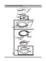
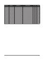
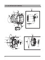
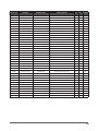
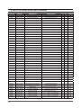
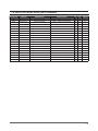
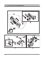
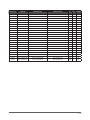
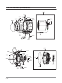
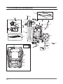
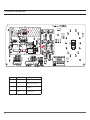
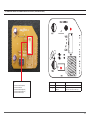
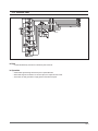
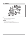
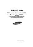
7-2. THE CONTROL PARTS (WF317AAW/XAA)
C0002
Y0171
Y0162
C0108
Y0170
C0044
C0029
C0105
W0032
R0158
R0085
R0025
R0157
J0028
W0032
R0159
N0009
R0036
R0155
R0173
R0160
R0014
7-2
I0003
R0096
R0019
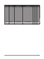
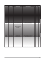
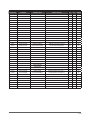
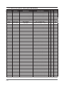
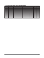
Location.No
CODE-NO
DESCRIPTION
SPECIFICATION
Un
Q’TY
SA/SNA
C0002
DC97-10513R
ASSY-S.PANEL CONTROL
WF317AAW/XAA,NEAT-W
PC
1
SNA
C0029
DC97-10511A
ASSY-KNOB ENCODER
FRONTIER,LOWES
PC
1
SA
C0044
DC64-01105A
BUTTON-PUSH(P)
WF326LAW,ABS,-,-,WHT,FRON
PC
1
SA
C0105
DC64-01108A
BUTTON-ENCODER
WF326LAW,ABS,-,-,WHT,FRON
PC
1
SA
C0108
DC66-00413A
LEVER-POWER
GW-PJT,POM,-,-,-,-,NTR,ENTRY
PC
1
SA
I0003
DC67-00089F
HOSE-WATER
WF326LAW,EPDM,ID5,OD9,T2,L190
PC
1
SA
J0028
DC61-01267A
CASE-PRE WASH
WINGS-PJT,PP(TB53),-,-,-,W
PC
1
SC
N0009
DC65-00008A
CLAMPER HOSE
SEW-DR605,SK5,-,-,YEL,ID14.
PC
10
SA
R0014
DC97-10336A
ASSY-DRAWER
WF316LAW,NEAT-WHT
PC
1
SA
R0019
DC97-07125M
ASSY-HOUSING DRAWER
WF337AAW,MAIN/HOT/BL
PC
1
SA
R0025
DC97-10960A
ASSY-PANEL DRAWER
WF316LAW,FRONTIER
PC
1
SA
R0036
DC61-01170A
BODY-DRAWER
GW-PJT,PP(TB-53),-,-,-,-,WHT
PC
1
SNA
R0085
DC61-01171A
GUIDE-LIQUID
GW-PJT,ABS,-,-,-,WHT,-
PC
1
SA
R0096
DC61-01167D
HOUSING-DRAWER(L)
WF337AAW,PP(TB-53),-,-
PC
1
SA
R0155
DC64-01113A
HANDLE-DRAWER
WF326LAW,ABS,-,-,-,-,WHT,F
PC
1
SNA
R0157
DC67-00121B
CAP-RINSE
MAH9700,PP(TB53),-,-,-,MUNSELL
PC
1
SA
R0158
DC67-00051B
HOSE-DRAWER
Q1636GW/XEU,EPDM,ID9.0,OD14.
M
1.48
SA
R0159
DC97-08800A
ASSY-S.HOUSING DRAWER
MAH9700AWW,-
PC
1
SA
R0160
DC97-08774A
ASSY-S.DRAWER
MAH9700AWW,-
PC
1
SA
R0173
DC63-00516A
COVER-DETERGENT
GW-PJT,PP(TB-53),-,-,-,-
PC
1
SNA
W0032
DC62-00142G
VALVE-WATER
V-0119,NYLON #6,123x55x55,1~
PC
1
SA
W0032
DC62-30314K
VALVE-WATER
V-0117,NYLON #6,83x45,1~8(10
PC
1
SA
Y0162
MFS-F2WLHA-S0
ASSY PCB PARTS(S)
MFS-F2WLHA-S0
PC
1
SA
Y0170
MFS-WF317-T0
ASSY-PCB PARTS
FRONTIER PJT
PC
1
SA
Y0171
MFS-WF317-00
ASSY-PCB PARTS(M)
FRONTIER PJT
PC
1
SA
7-3
7-4
D0066
D0010
D0106
D0001
D0061
Z0036
D0081
D0048
D0107
F0064
D0005
D0072
D0108
Z0027
C0058
R0030
D0106
7-3. THE DOOR PARTS (WF317AAW/XAA)
Location.No
CODE-NO
DESCRIPTION
C0058
DC64-00519B
DOOR-LOCK S/W
D0001
DC97-10671D
ASSY-DOOR
SPECIFICATION
Un
Q’TY
SA/SNA
GW-PJT,PP-GF,-,-,-,-,BLK,1
PC
1
SA
WF317AAW,AG+ PRINT/POM LEVER PC
1
SA
D0005
DC97-10718A
ASSY-HINGE DOOR
FRONTIER-PJT,SINGLE
PC
1
SA
D0010
DC97-10338C
ASSY-COVER DOOR
WF317AAG/XAA,SILVER CARE
PC
1
SA
D0048
DC61-01222A
BRACKET-HINGE
27-DRYER,HGI,T2.0,-,-,-,-
PC
1
SA
D0061
DC64-00504B
DOOR-GLASS
SEW-HW125,SODALIME,-,-,-,-,-,
PC
1
SC
D0066
DC64-01120A
DOOR-SAFETY
WF326LAW,PET,T2.8,-,-,-,NTR,
PC
1
SA
D0072
DC61-00891A
GUIDE-HINGE
HAUZEN(DOM),POM,-,-,-,WHT,HI
PC
4
SA
D0081
DC61-01520A
HOLDER-GLASS
WF326LAW,PP(TB53),T2.8,-,-,
PC
1
SA
D0106
DC63-00673A
COVER-DOOR
WF316LAW,ABS,T2.8,-,-,-,-,CR-
PC
1
SNA
D0106
DC63-00693A
COVER-DOOR SWITCH
FRONTIER,PP(V0),-,-,-,
PC
1
SA
D0107
DC66-00326A
LEVER-DOOR
TS85-PJT,POM,-,W24,L54,-,WHT,
PC
1
SA
D0108
DC61-01532A
HINGE-DOOR
WF326LAW,ZNDC,T3.8,-,-,-,-,FR
PC
1
SA
F0064
DC97-10340A
ASSY-FRAME FRONT
WF316LAW,NEAT-WHT/FRONT
PC
1
SA
R0030
DC97-04973B
ASSY-WIRE DIAPHRAGM
SEW-HFR1637AR,STS304
PC
1
SNA
Z0027
6001-001773
SCREW-MACHINE
TH,+,-,M5,L12,PASS,STS430,
PC
2
SA
Z0036
6001-001668
SCREW-MACHINE
TH,+,M5,L16,PASS,STS430,FP
PC
1
SA
7-5
7-4. THE TUB PARTS (WF317AAW/XAA)
R0001
R0021
I0079
W0031
N0008
U0079
U0029
I0046
U0038
R0007
I0078
U0354
U0367
U0365
U0086
R0006
N0010
U0384
U0363
U0358
U0133
U0320
W0005
A0353
U0078
U0185
W0031
W0031
U0078
U0364
H0075
U0097
Z0004
U0016
U0016
U0362
U0353
U0112
U0359
N0018
I0043
7-6
U0363
U0385
U0133
U0320
U0112
U0364
Location.No
CODE-NO
DESCRIPTION
SPECIFICATION
Un
Q’TY
SA/SNA
A0353
DC61-01257B
SPRING ETC-HANGER
Frontier,SWC,4.2,21.6,
PC
2
SA
H0075
DC31-00049A
MOTOR BLDC-DRUM
POM1300,0~1200,-,DC310V,
PC
1
SA
I0043
DC67-00126A
HOSE-DRAIN
GW-PJT,EPDM,OD 68,-,T2.0,-,BL
PC
1
SA
I0046
DC67-00265A
HOSE-DRAWER TUB
MACH,EPDM,-,-,-,-,BLK,-
PC
1
SA
I0078
DC67-00124A
HOSE-PRESSURE
GW-PJT,EPDM,-,-,-,-,BLK,-
PC
1
SA
I0079
DC97-12748A
ASSY-HOSE DRAWER TUB
SEW-HFR167AR,MACH-P
PC
1
SA
N0008
DC61-70029C
SPRING-CLIP
SEW-HW125,HSWR67,CD1.2,ID8.5
PC
1
SA
N0010
DC65-00009A
CLAMPER HOSE
TS85-PJT,HSWR,-,-,YEL,OD24/
PC
1
SA
N0018
DC65-00014A
CLAMPER HOSE
GW-PJT,HSWR,-,ID82,ZPC2,HOS
PC
1
SA
R0001
DC97-10337A
ASSY-DRUM
WF326LAW,FRONTIER
PC
1
SA
R0006
DC66-00434A
DRUM-LIFTER
WF326LAW,PP(TI42),-,-,L314,G
PC
3
SA
R0007
DC97-06986A
ASSY-FLANGE SHAFT
GW-PJT,ALDC+SM45C/DD-T
PC
1
SA
R0021
DC97-12747A
ASSY-GUIDE WATER
WF337LAW,FRONTIER II
PC
1
SNA
U0016
DC62-00156A
SEAL-OIL
TS85-PJT,NBR(SD45.5),BLK,-,-,-
PC
1
SA
U0029
DC64-00802A
DOOR-DIAPHRAGM
GW-PJT,EPDM,T1.5,-,-,-,GR
PC
1
SA
U0038
DC97-04981D
ASSY-CLAMP DIAPHGRAM
WINGS-PJT,HSWR/ZPC4
PC
1
SA
U0078
DC97-08649D
ASSY-SEMI TUB BACK
WF-G126AW,FRONTIER/VE
PC
1
SNA
U0079
DC97-08650F
ASSY-SEMI TUB FRONT
WF337AAW,15%/HEATER/
PC
1
SA
U0086
DC67-00139A
WEIGHT-BALANCER(F)
GW-PJT,GC,-,-,-,RED,F
PC
2
SA
U0097
6011-001548
M7.5,L30,ZPC(YEL),SWRCH18A,HEX
PC
20
SA
U0112
DC61-01338B
DR130,SBHG1-A(GI
PC
1
SA
GW-PJT,STEEL+PP+RUBBER,40N,
PC
2
SA
GW-PJT,-,-,-,-,-,-,60N
PC
2
SA
U0133
DC66-00343E
BOLT-ETC
BRACKET-HOUSING
BEARING
DAMPER-SHOCK
U0133
DC66-00343C
DAMPER-SHOCK
U0185
DC67-00155A
HOSE-O.F(I)
WINGS-PJT,EPDM,-,-,T2.0,-,BL
PC
1
SA
U0320
DC60-40141A
BOLT-HEX
SM10C/DAMPER,HEX,M8,L66,-,ZPC2
PC
2
SA
U0320
DC60-40141A
BOLT-HEX
SM10C/DAMPER,HEX,M8,L66,-,ZPC2
PC
2
SA
U0353
DC60-60044A
WASHER-PLAIN
-,ID10.5,OD30,T3,-,STS304
PC
1
SA
U0354
6031-001523
WASHER-WAVE
SK5,-,ID35,OD45,T0.6,ZPC2,-
PC
1
SA
U0358
DC47-00006G
HEATER
-,GW-PJT,STS316L,900W,7.18~7.8
PC
1
SA
U0359
DC61-01482A
BRACKET-HEATER
GW-PJT,STS430/304,T0.5,W9
PC
1
SA
U0362
DC60-60049A
WASHER-SPRING
-,ID10.5,OD18,T2.5,-,SIR
PC
1
SA
U0363
DC65-20008C
CABLE CLAMP
DA-8N,NYLON#66,-,-,NTR,ID13.
PC
2
SA
U0363
DC65-20008C
CABLE CLAMP
DA-8N,NYLON#66,-,-,NTR,ID13.
PC
1
SA
U0363
DC63-00820A
COVER-HEATER
WF337AAW,PP(V0),-,-,-,-,-,-
PC
1
SA
U0364
DC69-00804A
PACKING-TUB
GW-PJT,EPDM-FORM,-,PI8,W624,
PC
1
SA
U0365
DC97-02412A
ASSY-BOLT
SWF-P12,MOTOR, M8*L62
PC
4
SA
U0367
DC63-10003E
SPONGE-HOSE AIR
GW-PJT,HB22-GREY,-,T130,
PC
1
SA
U0367
DC63-10003C
SPONGE-HOSE AIR
POL,GRY,SWF-P12,HB22-GRE
PC
1
SA
U0384
DC61-01414A
BRACKET-TUB(F)
WINGS-PJT,SBHG1-A,T0.4,-,
PC
1
SA
U0385
DC61-01431B
BRACKET-TUB(B)
WINGS-PJT,SBHG1-A,T0.4,-,
PC
1
SA
W0005
DC96-01417A
ASSY-HEATER
WF337AAW,COVER-HEATER +HEATE
PC
1
SA
W0031
DC72-00001D
BAND-RING
WINGS-PJT,HSWR,T2.4,-,-,YEL,ID
PC
1
SA
W0031
DC72-00055A
BAND-RING
27” Washer,HSWR,#2/ M4x35,-,-,
PC
1
SA
W0031
DC72-00001E
BAND-RING
SEW-HTR122L,HSWR,#3.5,-,ID #49
PC
1
SNA
Z0004
DC60-50148B
NUT-HEX
SM20C(NYLON),M12,-,-,ZPC3(YEL)
PC
1
SA
7-7
7-5. THE FRAME PARTS (WF317AAW/XAA)
P0053
P0001
Y0162
U0380
Z0048
J0013
U0161
F0223
J0019
Q0006
I0030
Y0162
F0125
A0352
J0025
Z0047
I0023
W0036
A0352
N0001
Z0047
W0002
J0017
J0029
A0372
X0051
F0028
( ASSY-PUMP DRAIN )
A0282
U0380
( ASSY-ABSORBER )
B0070
A:
B:
B
N0006
B0045
B0073
J0013
W0004
A0083
I0040
I0040
A0025
B
B
A
B
A
A
B
A
A
7-8
R0161
Location.No
CODE-NO
DESCRIPTION
SPECIFICATION
A0025
DC97-07448B
ASSY-FIXER TUB
WF337AAW,YELLOW
A0083
DC61-00274A
GUIDE-HOSE
P/PV/M,PP,-,-,-,WHT,FRAME/DRA
Un
Q’TY
SA/SNA
PC
4
SNA
PC
1
SA
A0282
DC63-00522A
COVER-BACK
GW-PJT,GI,T0.4,W426,L507,-,-,
PC
1
SA
A0352
DC61-01548A
GUIDE-SPRING
GW-PJT,POM,-,-,-,NTR,-
PC
2
SA
A0372
DC97-08740D
ASSY-CAP O.F
WF337AAW,FRONTIER2
PC
1
SA
B0045
DC61-01652A
LEG-RING
K4-PJT,Nylon66+GF30,NON,SIL,L1
PC
1
SNA
B0070
DC97-12560A
ASSY-LEG
WF206LNW,MARS-PJT
PC
4
SA
B0073
DC61-01747A
LEG-RUBBER
MARS,BUTYL+SWRCH10A,-,GRY+YEL
PC
1
SA
F0028
DC97-06995J
ASSY-FRAME
WF327LAW,FRONTIER II
PC
1
SNA
F0125
DC61-01166A
FRAME-PLATE(U)
GW-PJT,EGI,-,-,-,T1.6,-,-
PC
1
SA
F0223
DC62-00202A
VALVE-CHECK
WINGS,EPDM,PO30,1~10BAR,BLK,
PC
1
SA
I0023
DC97-12534B
ASSY-HOSE DRAIN(I)
WF337AAW,L1920/BLOW-S
PC
1
SA
I0030
DC62-10278A
HOSE-HANGER
-,PP(JS20),-,-,-,-,NTR,-
PC
1
SA
I0040
DC62-00075A
HOSE-WATER(H)
-,NBR+NYLON,ID10.2,OD16.5,
PC
1
SA
I0040
DC62-00075B
HOSE-WATER(C)
-,NBR+NYLON,ID10.2,OD16.5,
PC
1
SC
J0013
DC96-01414A
ASSY-PUMP DRAIN
WF337AAW,FRONTIER II
PC
1
SA
J0017
DC61-01853A
BRACKET-PUMP
WF337AAW,SGCC(GI),T1.2,-,-,
PC
1
SA
J0019
DC61-01871A
CASE-PUMP
WF337AAW,PP(5113MF6),-,-,-,WHT
PC
1
SNA
J0025
DC31-00054A
PUMP-DRAIN
-,120V,60Hz,40mm,80W/3600RPM
PC
1
SNA
J0029
DC63-00766A
CUSHION-PUMP
WF206LNW,EPDM,-,-,-,-,MARS-
PC
1
SA
N0001
DC61-00133A
CLAMPER HOSE
P1291,PP(BJ-730),ID24.5,OD2
PC
1
SNA
N0006
DC61-40081A
HOLDER-WIRE
DAWH-2NC,NYLON66,-,-,-,-,NTR
PC
4
SA
N0006
DC61-40081A
HOLDER-WIRE
DAWH-2NC,NYLON66,-,-,-,-,NTR
PC
4
SA
P0001
DC97-12878B
ASSY-COVER TOP
WF317,NEAT-WHT
PC
1
SNA
P0053
DC63-00523G
WF206LNW,SECC(EGI),T0.8,-,-,-,
PC
1
SNA
Q0006
DC97-03716C
SEW-3HW123,DN-S14T/
PC
1
SA
R0161
DC62-40178A
COVER-TOP
ASSY-SENSOR
PRESSURE
SEAL-WATER
-,NR,BLK,-,-,-,ID12XOD25XT3
PC
4
SA
U0161
DC61-01200B
GUIDE-WIRE
WF206LNW,SGCC(GI),T0.8,-,-,-,
PC
1
SA
U0380
DC97-08635H
ASSY-ABSORBER
WF316,WEIGHT 390g+305g(SCP
PC
1
SA
W0002
DC96-00757A
ASSY POWER CORD
GW-PJT,GW,UL/CSA,3/16AWG
PC
1
SA
W0004
DC96-01043F
ASSY-M.WIRE HARNESS
FRONTIER MC,AG KIT/
PC
1
SA
W0036
DC29-00013A
FILTER-EMI
LFT-215G,WINGS_PJT,250VAC,15A
PC
1
SA
X0051
DC99-00815A
ASSY-CUSHION PUMP
WF206LNW,MARS-PJT
PC
3
SA
Y0162
MES-AG3MOD-S2
ASSY PCB PARTS(S)
MES-AG3MOD-S2
PC
1
SA
Y0162
MFS-MEMS-00
ASSY PCB PARTS(S)
MES-MEMS-00
PC
1
SA
Z0047
6009-001458
SCREW-SPECIAL
CH,+,-,M4,L10,ZPC3(BLK),SW
PC
2
SA
Z0048
6009-001476
SCREW-HEX
HEX,+,-,M5,L10,ZPC3(BLK),SWRCH
PC
2
SA
7-9
7-6. PARTS LIST (SA/SC others) (WF317AAW/XAA)
Location.No
CODE-NO
DESCRIPTION
SPECIFICATION
Un
Q’TY
SA/SNA
A0028
A0028
DC61-01586B
BRACKET-FIXER(L)
WF206LNW,SGCC(GI),T1.0,
PC
1
SA
DC61-01723A
BRACKET-FIXER(O/L)
WF206LNW,SGCC(GI),T2.
PC
2
SA
A0029
DC61-01587B
BRACKET-FIXER(R)
WF206LNW,SGCC(GI),T1.0,
PC
1
SA
A0034
DC60-40146A
BOLT-SPANER
-,HR,-,T2.3,OD36,-,BLK,-,-
PC
1
SA
A0043
DC61-10688A
CAP-FIXER
SWF-P12,PP(TB53),-,-,-,WHT,-,
PC
4
SA
A0043
DC61-10688B
CAP-FIXER
SEW-HFR167AR,PP(TB53),T1.5,-,-
PC
2
SA
A0055
DC61-01679A
CLIP-HOSE
SEW-HFR177AR,SK5,T1.6,NTR,ID37
PC
1
SA
A0125
6046-000310
STAND OFF
ID11.5,L2,NTR,NYLON66,DAWH-3NA
PC
4
SA
A0363
DC61-70029D
SPRING ETC-CLIP
WF337,HSWR67,CD1.6,ID8.5
PC
1
SA
B0027
DC97-12492A
ASSY-WEIGHT
WF316,WEIGHT 390g(SCP1)
PC
1
SA
B0027
DC97-12493A
ASSY-WEIGHT
WF316,WEIGHT 305g(SCP1)
PC
1
SA
D0105
DC61-01576A
SUPPORT-HINGE
FRONTIER-PJT,STS430,T1.2,-
PC
1
SA
D0111
DC72-00034B
SPONGE-EPDM
MAH2400,EPDM,-,T1,W15,L500,W
PC
3
SA
I0044
DC97-08633D
ASSY-HOSE PRESSURE
WF316LAW,HEATER/FRONT
PC
1
SA
I0045
DC67-00057A
HOSE-AIR
TS85-PJT,EPDM,-,-,-,-,BLK,-
PC
1
SA
J0020
DC63-00810A
COVER-PUMP
WF337AAW,PP(FH-44N),-,-,-,-,-
PC
1
SA
M0047
DC61-01736B
HOLDER-WIRE
WF337AAW,NYLON66,OD31,H15,L1
PC
1
SA
N0008
DC61-70029C
SPRING-CLIP
SEW-HW125,HSWR67,CD1.2,ID8.5
PC
1
SA
P0025
DC61-01839A
BRACKET-COVER TOP
WF337AAW,SGCC(GI),T1.6
PC
1
SA
P0025
DC61-01839A
BRACKET-COVER TOP
WF337AAW,SGCC(GI),T1.6
PC
1
SA
R0021
DC97-10417A
ASSY-GUIDE WATER
WF326LAW,FRONTIER
PC
1
SA
U0069
DC97-08632C
ASSY-GUIDE WIRE
WF206LNW,MARS-PJT/T0.8
PC
1
SA
U0320
DC60-40137A
BOLT-HEX
MARS-PJT,STS304,M8,-,P1.25,L30
PC
6
SA
U0320
6011-001565
BOLT-HEX
M6,L35.1,ZPC(YEL),SWCH25K,TAPP
PC
3
SA
U0353
DC60-60044A
WASHER-PLAIN
-,ID10.5,OD30,T3,-,STS304
PC
2
SA
U0353
DC60-60044A
WASHER-PLAIN
-,ID10.5,OD30,T3,-,STS304
PC
2
SA
U0353
6031-001531
WASHER-PLAIN
SCP1,-,ID7,OD14,T0.8,ZPC2(Y
PC
1
SA
U0363
6502-000127
CABLE CLAMP
DAWH-18NB,ID15,-,NYLON66,NTR
PC
3
SA
U0363
6502-000127
CABLE CLAMP
DAWH-18NB,ID15,-,NYLON66,NTR
PC
5
SA
U0379
DC67-00252A
WEIGHT-ABSORBER
WF316,SHP1(PO##),4mm,#70
PC
1
SA
U0379
DC67-00253A
WEIGHT-ABSORBER
WF316,SHP1(PO##),4mm,#70
PC
4
SA
U0379
DC67-00255A
WEIGHT-ABSORBER
WF316,SHP1(PO##),1mm,#70
PC
2
SA
U0379
DC67-00252A
WEIGHT-ABSORBER
WF316,SHP1(PO##),4mm,#70
PC
1
SA
U0379
DC67-00253A
WEIGHT-ABSORBER
WF316,SHP1(PO##),4mm,#70
PC
2
SA
U0379
DC67-00255A
WEIGHT-ABSORBER
WF316,SHP1(PO##),1mm,#70
PC
5
SA
U0382
DC61-01820A
FIXER-WEIGHT ABSORBER
WF316,SM10C,L25/D6
PC
5
SA
U0382
DC61-01821A
FIXER-WEIGHT ABSORBER
WF316,SM10C,L20/ D
PC
5
SA
U0395
DC97-12814A
ASSY-BRACKET SPRING(R)
WF337AAW,FRONTIER
PC
1
SA
U0396
DC97-12813A
ASSY-BRACKET SPRING(L)
WF337AAW,FRONTIER
PC
1
SA
W0030
DC62-10022X
HOSE-PUMP
FRONTIER,PP,ID20.6,OD27,-,L192
PC
1
SA
W0059
DC63-10002D
SPONGE-HARNESS
-,PU-FOAM,-,T10,W100,L80,
PC
4
SA
X0050
DC61-01445A
GUIDE-CUSHION
MAH98700AWW,PP,T2.8,-,-,-,
PC
1
SA
Z0008
6002-000444
SCREW-TAPPING
TH,+,-,2S,M4,L14,PASS,STS4
PC
3
SA
Z0008
6002-000444
SCREW-TAPPING
TH,+,-,2S,M4,L14,PASS,STS4
PC
12
SA
Z0008
6002-000444
SCREW-TAPPING
TH,+,-,2S,M4,L14,PASS,STS4
PC
1
SA
7-10
7-6. PARTS LIST (SA/SC others) (WF317AAW/XAA)
Location.No
CODE-NO
Z0008
6002-000444
Z0011
6002-001277
Z0013
6002-001279
Z0038
6002-000241
Z0055
Z0055
DESCRIPTION
SPECIFICATION
Un
Q’TY
SA/SNA
SCREW-TAPPING
TH,+,-,2S,M4,L14,PASS,STS4
SCREW-TAPPING
HEX,+,-,2,M6.5,L40,ZPC(WHT
PC
3
SA
PC
12
SA
SCREW-TAPPING
SCREW-TAPPING
PWH,+,-,1,M4,L12,PASS,STS4
PC
2
SA
TH,+,-,2S,M5,L12,ZPC(WHT),
PC
1
SA
6002-001374
6002-001374
SCREW-TAPPING
TH,+,WE,-,M4,L12,ZPC3 (WHT
PC
6
SA
SCREW-TAPPING
TH,+,WE,-,M4,L12,ZPC3 (WHT
PC
1
SA
Z0055
6002-001374
SCREW-TAPPING
TH,+,WE,-,M4,L12,ZPC3 (WHT
PC
2
SA
Z0055
6002-001374
SCREW-TAPPING
TH,+,WE,-,M4,L12,ZPC3 (WHT
PC
2
SA
Z0055
6002-001374
SCREW-TAPPING
TH,+,WE,-,M4,L12,ZPC3 (WHT
PC
15
SA
Z0056
6002-001376
SCREW-TAPPING
TH,+,-,1,M4,L12,ZPC3 (WHT)
PC
4
SA
Z0056
6002-001376
SCREW-TAPPING
TH,+,-,1,M4,L12,ZPC3 (WHT)
PC
4
SA
Z0056
6002-001376
SCREW-TAPPING
TH,+,-,1,M4,L12,ZPC3 (WHT)
PC
3
SA
Z0056
6002-001376
SCREW-TAPPING
TH,+,-,1,M4,L12,ZPC3 (WHT)
PC
1
SA
Z0056
6002-001376
SCREW-TAPPING
TH,+,-,1,M4,L12,ZPC3 (WHT)
PC
7
SA
Z0062
6002-000630
SCREW-TAPPING
PH,+,-,2S,M3,L8,ZPC(WHT),S
PC
1
SA
Z0064
DC97-14006A
ASSY-SCREW
WF203,SCREW-TAPPING(M4+L16,TH PC
2
SA
Z0065
6003-001563
SCREW-TAPTITE
TH,+,-,S,M4,L8,ZPC3(BLK),S
PC
2
SA
Z0065
6003-001563
SCREW-TAPTITE
TH,+,-,S,M4,L8,ZPC3(BLK),S
PC
1
SA
Z0065
6003-001563
SCREW-TAPTITE
TH,+,-,S,M4,L8,ZPC3(BLK),S
PC
4
SA
7-11
7-7. THE CONTROL PARTS (WF206BNW/XAA)
C0002
Y0161
Y0162
C0108
Y0163
C0044
C0029
C0105
W0032
R0158
R0085
R0025
W0032
R0157
R0159
N0009
R0036
R0155
R0173
R0015
R0014
7-12
R0096
R0019
Location.No
CODE-NO
DESCRIPTION
SPECIFICATION
Un
Q’TY
SA/SNA
C0002
DC97-12075B
ASSY-S.PANEL CONTROL
WF206BNW,MARS-PJT
PC
1
SA
C0029
DC97-10526A
ASSY-KNOB ENCODER
WF316BAW,BBY/CR-COATIN
PC
1
SA
C0044
DC64-01105A
BUTTON-PUSH(P)
WF326LAW,ABS,-,-,WHT,FRON
PC
1
SA
C0105
DC64-01132B
BUTTON-ENCODER
DV306BEW(SECA),ABS,-,-,WH
PC
1
SA
C0108
DC66-00413A
LEVER-POWER
GW-PJT,POM,-,-,-,-,NTR,ENTRY
PC
1
SA
N0009
DC65-00008A
CLAMPER HOSE
SEW-DR605,SK5,-,-,YEL,ID14.
PC
6
SA
R0014
DC97-10335D
ASSY-DRAWER
WF306BHW,NEAT-WHT/3-TRAY
PC
1
SA
R0015
DC97-08774B
ASSY-S. DRAWER
WF306LAW,NO-PRE WASH
PC
1
SA
R0019
DC97-07125L
ASSY-HOUSING DRAWER
WF206LNW,MAIN/HOT/BL
PC
1
SA
R0025
DC97-10961A
ASSY-PANEL DRAWER
WF316BAW,FRONTIER
PC
1
SNA
R0036
DC61-01170A
BODY-DRAWER
GW-PJT,PP(TB-53),-,-,-,-,WHT
PC
1
SNA
R0085
DC61-01171A
GUIDE-LIQUID
GW-PJT,ABS,-,-,-,WHT,-
PC
1
SA
R0096
DC61-01167A
HOUSING-DRAWER(L)
GW-PJT,PP(FH44N),-,-,-
PC
1
SA
R0155
DC64-01113A
HANDLE-DRAWER
WF326LAW,ABS,-,-,-,-,WHT,F
PC
1
SNA
R0157
DC67-00121B
CAP-RINSE
MAH9700,PP(TB53),-,-,-,MUNSELL
PC
1
SA
R0158
DC67-00051B
HOSE-DRAWER
Q1636GW/XEU,EPDM,ID9.0,OD14.
M
0.92
SA
R0159
DC97-08800A
ASSY-S.HOUSING DRAWER
MAH9700AWW,-
PC
1
SA
R0173
DC63-00516A
COVER-DETERGENT
GW-PJT,PP(TB-53),-,-,-,-
PC
1
SNA
W0032
DC62-30312J
VALVE-WATER
V-1245,NYLON #6,83x45,1~8(V1
PC
1
SA
W0032
DC62-30314K
VALVE-WATER
V-0117,NYLON #6,83x45,1~8(10
PC
1
SA
Y0161
MFS-WF206L-00
ASSY PCB PARTS(M)
MFS-WF206L-00
PC
1
SA
Y0162
MFS-WF206L-S0
ASSY PCB PARTS(S)
MFS-WF206L-S0
PC
1
SA
Y0163
MFS-WF206L-T0
ASSY-PCB PARTS
MFS-WF206L-T0
PC
1
SA
7-13
7-14
D0066
D0010
D0106
D0001
D0061
Z0036
D0081
D0048
D0107
F0064
D0005
D0072
D0108
Z0027
C0058
R0030
D0106
7-8. THE DOOR PARTS (WF206BNW/XAA)
Location.No
CODE-NO
DESCRIPTION
SPECIFICATION
Un
Q’TY
SA/SNA
C0058
DC64-00519B
DOOR-LOCK S/W
GW-PJT,PP-GF,-,-,-,-,BLK,1
PC
1
SA
D0001
DC97-10792G
ASSY-DOOR
WF206,-
PC
1
SA
D0005
DC97-10718A
ASSY-HINGE DOOR
FRONTIER-PJT,SINGLE
PC
1
SA
D0010
DC97-10342D
ASSY-COVER DOOR
DV2C6BEW/XAA,MARS-PJT/Cr
PC
1
SA
D0048
DC61-01222A
BRACKET-HINGE
27-DRYER,HGI,T2.0,-,-,-,-
PC
1
SA
D0061
DC64-00504B
DOOR-GLASS
SEW-HW125,SODALIME,-,-,-,-,-,
PC
1
SC
D0066
DC64-01120A
DOOR-SAFETY
WF326LAW,PET,T2.8,-,-,-,NTR,
PC
1
SA
D0072
DC61-00891A
GUIDE-HINGE
HAUZEN(DOM),POM,-,-,-,WHT,HI
PC
4
SA
D0081
DC61-01520A
HOLDER-GLASS
WF326LAW,PP(TB53),T2.8,-,-,
PC
1
SA
D0106
DC63-00674C
COVER-DOOR
DV2C6BEW/XAA,ABS,T2.8,-,-,-,B
PC
1
SNA
D0106
DC63-00693A
COVER-DOOR SWITCH
FRONTIER,PP(V0),-,-,-,
PC
1
SA
D0107
DC66-00326A
LEVER-DOOR
TS85-PJT,POM,-,W24,L54,-,WHT,
PC
1
SA
D0108
DC61-01532A
HINGE-DOOR
WF326LAW,ZNDC,T3.8,-,-,-,-,FR
PC
1
SA
F0064
DC97-10340A
ASSY-FRAME FRONT
WF316LAW,NEAT-WHT/FRONT
PC
1
SA
R0030
DC97-04973A
ASSY-WIRE DIAPHRAGM
TS85-PJT,FRAME-FRONT
PC
1
SA
Z0027
6001-001773
SCREW-MACHINE
TH,+,-,M5,L12,PASS,STS430,
PC
2
SA
Z0036
6001-001668
SCREW-MACHINE
TH,+,M5,L16,PASS,STS430,FP
PC
1
SA
7-15
7-9. THE TUB PARTS (WF206BNW/XAA)
R0001
P0148
W0031
N0008
U0079
U0029
I0046
U0038
R0007
I0078
U0354
U0367
U0365
U0086
R0006
N0010
U0133
U0320
A0353
U0078
U0185
W0031
W0031
U0078
U0364
H0075
U0097
Z0004
U0016
U0016
U0362
U0353
U0112
U0363
U0385
N0018
I0043
7-16
U0133
U0320
U0112
U0364
Location.No
CODE-NO
DESCRIPTION
SPECIFICATION
Un
Q’TY
SA/SNA
A0353
DC61-01257B
SPRING ETC-HANGER
Frontier,SWC,4.2,21.6,
PC
2
SA
H0075
DC31-00049A
MOTOR BLDC-DRUM
POM1300,0~1200,-,DC310V,
PC
1
SA
I0043
DC67-00126A
HOSE-DRAIN
GW-PJT,EPDM,OD 68,-,T2.0,-,BL
PC
1
SA
I0046
DC67-00122A
HOSE-DRAWER TUB
GW-PJT,EPDM,-,-,-,-,BLK,
PC
1
SA
I0078
DC67-00124A
HOSE-PRESSURE
GW-PJT,EPDM,-,-,-,-,BLK,-
PC
1
SA
N0008
DC61-70029C
SPRING-CLIP
SEW-HW125,HSWR67,CD1.2,ID8.5
PC
1
SA
N0010
DC65-00009A
CLAMPER HOSE
TS85-PJT,HSWR,-,-,YEL,OD24/
PC
1
SA
N0018
DC65-00014A
CLAMPER HOSE
GW-PJT,HSWR,-,ID82,ZPC2,HOS
PC
1
SA
P0148
DC61-01172A
GUIDE-WATER
GW-PJT,FRPP(GF15%),T2.5,-,-,
PC
1
SA
R0001
DC97-12224A
ASSY-DRUM
WF206LNW,MARS-PJT
PC
1
SA
R0006
DC66-00434A
DRUM-LIFTER
WF326LAW,PP(TI42),-,-,L314,G
PC
3
SA
R0007
DC97-12222A
ASSY-FLANGE SHAFT
WF206LNW,MARS-PJT
PC
1
SA
U0016
DC62-00223A
SEAL-OIL
GW-PJT,EPDM,BLK,-,W77.55,L12,6
PC
1
SA
U0029
DC64-00802A
DOOR-DIAPHRAGM
GW-PJT,EPDM,T1.5,-,-,-,GR
PC
1
SA
U0038
DC97-04981D
ASSY-CLAMP DIAPHGRAM
WINGS-PJT,HSWR/ZPC4
PC
1
SA
U0078
DC97-11526C
ASSY-SEMI TUB BACK
WF206LNW,NO-HEATER/VE
PC
1
SNA
U0079
DC97-08650D
ASSY-SEMI TUB FRONT
WF206LNW,12%/NO-HEAT
PC
1
SA
U0086
DC67-00139A
WEIGHT-BALANCER(F)
GW-PJT,GC,-,-,-,RED,F
PC
2
SA
U0097
6011-001548
M7.5,L30,ZPC(YEL),SWRCH18A,HEX
PC
20
SA
U0112
DC61-01338B
DR130,SBHG1-A(GI
PC
1
SA
U0133
DC66-00343C
BOLT-ETC
BRACKET-HOUSING
BEARING
DAMPER-SHOCK
GW-PJT,-,-,-,-,-,-,60N
PC
2
SA
U0133
DC66-00343E
DAMPER-SHOCK
GW-PJT,STEEL+PP+RUBBER,40N,
PC
2
SA
U0185
DC67-00155A
HOSE-O.F(I)
WINGS-PJT,EPDM,-,-,T2.0,-,BL
PC
1
SA
U0320
DC60-40141A
BOLT-HEX
SM10C/DAMPER,HEX,M8,L66,-,ZPC2
PC
2
SA
U0320
DC60-40141A
BOLT-HEX
SM10C/DAMPER,HEX,M8,L66,-,ZPC2
PC
2
SA
U0353
DC60-60044A
WASHER-PLAIN
-,ID10.5,OD30,T3,-,STS304
PC
1
SA
U0353
DC60-60044A
WASHER-PLAIN
-,ID10.5,OD30,T3,-,STS304
PC
2
SA
U0354
6031-001519
WASHER-WAVE
SK5,-,ID30,OD36,T0.5,ZPC2,3P
PC
1
SA
U0362
DC60-60049A
WASHER-SPRING
-,ID10.5,OD18,T2.5,-,SIR
PC
1
SA
U0363
DC65-20008C
CABLE CLAMP
DA-8N,NYLON#66,-,-,NTR,ID13.
PC
1
SA
U0364
DC69-00804A
PACKING-TUB
GW-PJT,EPDM-FORM,-,PI8,W624,
PC
1
SA
U0365
DC97-02412A
ASSY-BOLT
SWF-P12,MOTOR, M8*L62
PC
4
SA
U0367
DC63-10003C
SPONGE-HOSE AIR
POL,GRY,SWF-P12,HB22-GRE
PC
1
SA
U0385
DC61-01431B
BRACKET-TUB(B)
WINGS-PJT,SBHG1-A,T0.4,-,
PC
1
SA
W0031
DC72-00001A
BAND-RING
DRUM-MODEL,HSWR,-,-,-,,YEL,ID6
PC
1
SA
W0031
DC72-00001D
BAND-RING
WINGS-PJT,HSWR,T2.4,-,-,YEL,ID
PC
1
SA
W0031
DC72-00055A
BAND-RING
27” Washer,HSWR,#2/ M4x35,-,-,
PC
1
SA
Z0004
DC60-50148B
NUT-HEX
SM20C(NYLON),M12,-,-,ZPC3(YEL)
PC
1
SA
7-17
7-10. THE FRAME PARTS (WF206BNW/XAA)
P0053
P0001
Y0162
U0380
Z0048
J0013
U0161
F0223
J0019
I0030
Q0006
F0125
A0352
J0025
Z0047
I0023
W0036
A0352
N0001
Z0047
W0002
J0017
J0029
A0372
X0051
F0028
( ASSY-PUMP DRAIN )
A0282
U0380
( ASSY-ABSORBER )
B0070
A:
B:
B
N0006
B0045
B0073
J0013
W0004
A0083
I0040
I0040
A0025
B
B
A
B
A
A
B
A
A
7-18
R0161
Location.No
CODE-NO
DESCRIPTION
SPECIFICATION
Un
Q’TY
SA/SNA
A0025
DC97-07448B
ASSY-FIXER TUB
WF337AAW,YELLOW
PC
4
SNA
A0083
DC61-00274A
GUIDE-HOSE
P/PV/M,PP,-,-,-,WHT,FRAME/DRA
PC
1
SA
A0282
DC63-00522A
COVER-BACK
GW-PJT,GI,T0.4,W426,L507,-,-,
PC
1
SA
A0352
DC61-01548A
GUIDE-SPRING
GW-PJT,POM,-,-,-,NTR,-
PC
2
SA
A0372
DC97-08740D
ASSY-CAP O.F
WF337AAW,FRONTIER2
PC
1
SA
B0045
DC61-01652A
LEG-RING
K4-PJT,Nylon66+GF30,NON,SIL,L1
PC
1
SNA
B0070
DC97-12560A
ASSY-LEG
WF206LNW,MARS-PJT
PC
4
SA
B0073
DC61-01747A
LEG-RUBBER
MARS,BUTYL+SWRCH10A,-,GRY+YEL
PC
1
SA
F0028
DC97-06995G
ASSY-FRAME
WF206LNW,NEAT-WHT/T0.8/VENT-1
PC
1
SA
F0125
DC61-01166A
FRAME-PLATE(U)
GW-PJT,EGI,-,-,-,T1.6,-,-
PC
1
SA
F0223
DC62-00202A
VALVE-CHECK
WINGS,EPDM,PO30,1~10BAR,BLK,
PC
1
SA
I0023
DC97-12534B
ASSY-HOSE DRAIN(I)
WF337AAW,L1920/BLOW-S
PC
1
SA
I0030
DC62-10278A
HOSE-HANGER
-,PP(JS20),-,-,-,-,NTR,-
PC
1
SA
I0040
DC62-00075A
HOSE-WATER(H)
-,NBR+NYLON,ID10.2,OD16.5,
PC
1
SA
I0040
DC62-00075B
HOSE-WATER(C)
-,NBR+NYLON,ID10.2,OD16.5,
PC
1
SC
J0013
DC96-01414A
ASSY-PUMP DRAIN
WF337AAW,FRONTIER II
PC
1
SA
J0017
DC61-01853A
BRACKET-PUMP
WF337AAW,SGCC(GI),T1.2,-,-,
PC
1
SA
J0019
DC61-01871A
CASE-PUMP
WF337AAW,PP(5113MF6),-,-,-,WHT
PC
1
SNA
J0025
DC31-00054A
PUMP-DRAIN
-,120V,60Hz,40mm,80W/3600RPM
PC
1
SNA
J0029
DC63-00766A
CUSHION-PUMP
WF206LNW,EPDM,-,-,-,-,MARS-
PC
1
SA
N0001
DC61-00133A
CLAMPER HOSE
P1291,PP(BJ-730),ID24.5,OD2
PC
1
SNA
N0006
DC61-40081A
HOLDER-WIRE
DAWH-2NC,NYLON66,-,-,-,-,NTR
PC
4
SA
N0006
DC61-40081A
HOLDER-WIRE
DAWH-2NC,NYLON66,-,-,-,-,NTR
PC
5
SA
P0001
DC97-08634J
ASSY-COVER TOP
WF206LNW,NEAT-WHT
PC
1
SA
P0053
DC63-00523G
WF206LNW,SECC(EGI),T0.8,-,-,-,
PC
1
SNA
Q0006
DC97-03716C
SEW-3HW123,DN-S14T/
PC
1
SA
R0161
DC62-40178A
COVER-TOP
ASSY-SENSOR
PRESSURE
SEAL-WATER
-,NR,BLK,-,-,-,ID12XOD25XT3
PC
4
SA
U0161
DC61-01200B
GUIDE-WIRE
WF206LNW,SGCC(GI),T0.8,-,-,-,
PC
1
SA
U0380
DC97-08635G
ASSY-ABSORBER
WF306,WEIGHT 390g(SCP1)
PC
1
SA
W0002
DC96-00757A
ASSY POWER CORD
GW-PJT,GW,UL/CSA,3/16AWG
PC
1
SA
W0004
DC96-01043D
ASSY-M.WIRE HARNESS
WF206ANW,MARS WASHER
PC
1
SA
W0036
DC29-00013A
FILTER-EMI
LFT-215G,WINGS_PJT,250VAC,15A
PC
1
SA
X0051
DC99-00815A
ASSY-CUSHION PUMP
WF206LNW,MARS-PJT
PC
3
SA
Y0162
MFS-MEMS-00
ASSY PCB PARTS(S)
MES-MEMS-00
PC
1
SA
Z0047
6009-001458
SCREW-SPECIAL
CH,+,-,M4,L10,ZPC3(BLK),SW
PC
2
SA
Z0048
6009-001476
SCREW-HEX
HEX,+,-,M5,L10,ZPC3(BLK),SWRCH
PC
2
SA
7-19
7-11. PARTS LIST (SA/SC others) (WF206BNW/XAA)
Location.No
CODE-NO
DESCRIPTION
SPECIFICATION
Un
Q’TY
SA/SNA
A0028
DC61-01723A
BRACKET-FIXER(O/L)
WF206LNW,SGCC(GI),T2.
PC
1
SA
A0028
DC61-01723A
BRACKET-FIXER(O/L)
WF206LNW,SGCC(GI),T2.
PC
1
SA
A0028
DC61-01586B
BRACKET-FIXER(L)
WF206LNW,SGCC(GI),T1.0,
PC
1
SA
A0029
DC61-01587B
BRACKET-FIXER(R)
WF206LNW,SGCC(GI),T1.0,
PC
1
SA
A0032
DC97-12305A
ASSY-BRACKET FIXER(O/L)
WF206LNW,BRACKET
PC
1
SA
A0033
DC97-12306A
ASSY-BRACKET FIXER(O/R)
WF206LNW,Bracket
PC
1
SA
A0034
DC60-40146A
BOLT-SPANER
-,HR,-,T2.3,OD36,-,BLK,-,-
PC
1
SA
A0043
DC61-10688A
CAP-FIXER
SWF-P12,PP(TB53),-,-,-,WHT,-,
PC
6
SA
A0055
DC61-01679A
CLIP-HOSE
SEW-HFR177AR,SK5,T1.6,NTR,ID37
PC
1
SA
A0125
6046-000310
STAND OFF
ID11.5,L2,NTR,NYLON66,DAWH-3NA
PC
4
SA
B0027
DC97-12492A
ASSY-WEIGHT
WF316,WEIGHT 390g(SCP1)
PC
1
SA
D0105
DC61-01576A
SUPPORT-HINGE
FRONTIER-PJT,STS430,T1.2,-
PC
1
SA
D0111
DC72-00034H
SPONGE-EPDM
WF316LAW,YOUNGBOARD,-,T1.0,W
PC
1
SA
D0111
DC72-00034B
SPONGE-EPDM
MAH2400,EPDM,-,T1,W15,L500,W
PC
3
SA
J0020
DC63-00810A
COVER-PUMP
WF337AAW,PP(FH-44N),-,-,-,-,-
PC
1
SA
M0047
DC61-01736B
HOLDER-WIRE
WF337AAW,NYLON66,OD31,H15,L1
PC
1
SA
U0069
DC97-08632C
ASSY-GUIDE WIRE
WF206LNW,MARS-PJT/T0.8
PC
1
SA
U0113
DC61-01817A
BUSH-BEARING
Frontier,STS304,ID30,OD62,L
PC
1
SA
U0320
DC60-40137A
BOLT-HEX
MARS-PJT,STS304,M8,-,P1.25,L30
PC
6
SA
U0320
6011-001565
BOLT-HEX
M6,L35.1,ZPC(YEL),SWCH25K,TAPP
PC
3
SA
U0353
DC60-60044A
WASHER-PLAIN
-,ID10.5,OD30,T3,-,STS304
PC
2
SA
U0353
6031-001531
WASHER-PLAIN
SCP1,-,ID7,OD14,T0.8,ZPC2(Y
PC
1
SA
U0363
DC65-20008C
CABLE CLAMP
DA-8N,NYLON#66,-,-,NTR,ID13.
PC
2
SA
U0363
6502-000127
CABLE CLAMP
DAWH-18NB,ID15,-,NYLON66,NTR
PC
3
SA
U0363
6502-000127
CABLE CLAMP
DAWH-18NB,ID15,-,NYLON66,NTR
PC
4
SA
U0367
DC63-10003E
SPONGE-HOSE AIR
GW-PJT,HB22-GREY,-,T130,
PC
1
SA
U0379
DC67-00252A
WEIGHT-ABSORBER
WF316,SHP1(PO##),4mm,#70
PC
1
SA
U0379
DC67-00253A
WEIGHT-ABSORBER
WF316,SHP1(PO##),4mm,#70
PC
4
SA
U0379
DC67-00255A
WEIGHT-ABSORBER
WF316,SHP1(PO##),1mm,#70
PC
2
SA
U0382
DC61-01820A
FIXER-WEIGHT ABSORBER
WF316,SM10C,L25/D6
PC
5
SA
W0030
DC62-10022X
HOSE-PUMP
FRONTIER,PP,ID20.6,OD27,-,L192
PC
1
SA
W0035
DC32-00010A
THERMISTOR
-,11982OHM AT 25#,-,-55~155,-
PC
1
SA
W0059
DC63-10002D
SPONGE-HARNESS
-,PU-FOAM,-,T10,W100,L80,
PC
4
SA
W0063
DC69-00824A
PACKING-THERMISTOR
GW-PJT,EPDM,-,-,W17,-
PC
1
SA
X0050
DC61-01445A
GUIDE-CUSHION
MAH98700AWW,PP,T2.8,-,-,-,
PC
1
SA
Z0008
6002-000444
SCREW-TAPPING
TH,+,-,2S,M4,L14,PASS,STS4
PC
3
SA
Z0008
6002-000444
SCREW-TAPPING
TH,+,-,2S,M4,L14,PASS,STS4
PC
12
SA
Z0008
6002-000444
SCREW-TAPPING
TH,+,-,2S,M4,L14,PASS,STS4
PC
1
SA
Z0008
6002-000444
SCREW-TAPPING
TH,+,-,2S,M4,L14,PASS,STS4
PC
3
SA
Z0011
6002-001277
SCREW-TAPPING
HEX,+,-,2,M6.5,L40,ZPC(WHT
PC
12
SA
Z0013
6002-001279
SCREW-TAPPING
PWH,+,-,1,M4,L12,PASS,STS4
PC
2
SA
Z0038
6002-000241
SCREW-TAPPING
TH,+,-,2S,M5,L12,ZPC(WHT),
PC
1
SA
Z0055
6002-001374
SCREW-TAPPING
TH,+,WE,-,M4,L12,ZPC3 (WHT
PC
6
SA
Z0055
6002-001374
SCREW-TAPPING
TH,+,WE,-,M4,L12,ZPC3 (WHT
PC
15
SA
Z0055
6002-001374
SCREW-TAPPING
TH,+,WE,-,M4,L12,ZPC3 (WHT
PC
1
SA
7-20
7-11. PARTS LIST (SA/SC others) (WF206BNW/XAA)
Location.No
CODE-NO
DESCRIPTION
SPECIFICATION
Un
Q’TY
SA/SNA
Z0056
6002-001376
SCREW-TAPPING
TH,+,-,1,M4,L12,ZPC3 (WHT)
PC
4
SA
Z0056
6002-001376
SCREW-TAPPING
TH,+,-,1,M4,L12,ZPC3 (WHT)
PC
3
SA
Z0056
6002-001376
SCREW-TAPPING
TH,+,-,1,M4,L12,ZPC3 (WHT)
PC
2
SA
Z0056
6002-001376
SCREW-TAPPING
TH,+,-,1,M4,L12,ZPC3 (WHT)
PC
2
SA
Z0056
6002-001376
SCREW-TAPPING
TH,+,-,1,M4,L12,ZPC3 (WHT)
PC
1
SA
Z0062
6002-000630
SCREW-TAPPING
PH,+,-,2S,M3,L8,ZPC(WHT),S
PC
1
SA
Z0064
DC97-14006A
ASSY-SCREW
WF203,SCREW-TAPPING(M4+L16,TH PC
2
SA
Z0065
6003-001563
SCREW-TAPTITE
TH,+,-,S,M4,L8,ZPC3(BLK),S
PC
2
SA
Z0065
6003-001563
SCREW-TAPTITE
TH,+,-,S,M4,L8,ZPC3(BLK),S
PC
1
SA
Z0065
6003-001563
SCREW-TAPTITE
TH,+,-,S,M4,L8,ZPC3(BLK),S
PC
4
SA
7-21
Memo
7-22
8. BLOCK DIAGRAM
8-1
Memo
8-2
9. WIRING DIAGRAM
9-1. WIRING DIAGRAM
9-1
9-2. REFERENCE INFORMATION
BLK
BLU
GRN
GRY
NTR
ORG
PNK
RED
SKYBLU
BLACK
BLUE
GREEN
GRAY
NEUTRAL
ORANGE
PINK
RED
SKYBLUE
VIO
WHT
YEL
VIOLET
WHITE
YELLOW
N.F (Noise Filter)
SENSOR PRESSURE
SILVER NANO
DRY CONDENSOR
DRY MOTOR
THERMOSTAT
DOOR LOCK
DOOR OPEN
DOOR S/W
HOT VALVE
MAIN VALVE
PRE VALVE
DRY VALVE
DRAIN MOTOR
WATER HEATER
STEAM HEATER
DRY HEATER
SPLICE
9-2
10. PCB DIAGRAM
10-1. MAIN PCB LAYOUT
Item
Part Number
Description
1
Ry10
Main Power Relay
2
Ry9
Heater Relay
3
PC1~3
4
BD1
5
IC9
Check for the Frequency
Make the Zerocross
Door Lock Check
It Work to Change the AC to
the DC
Item
Part Number
Description
8
CE7,8
Charge the DC LINK (300V)
9
Fuse1
Limit the Over-Current
10
IPM1
Control to Motor
11
Ry1~8
Turn On/Off the Load
(Valve etc.)
12
IC7,8
Drive the Relay
Supply the Current to the
Acting Current
13
BZ1
Making a Sound
Making a stable DC
6
LVT1
Chopping the DC Link
7
IC1
Regulation for the 5V
10-1
10-2. CONNECTOR & RELAY TERMINALS DESCRIPTION (MAIN PBA)
Relay 9
CN9
1. Connects to Washing Heater
2. Connects to EMI Filter
(Remove the Noise/AC2)
1. Connects to Motor (U Phase)
2. Connects to Motor (V Phase)
3. Connects to Motor (W Phase)
CN10
1. Connects to Main Valve
2. Connects to Hot Valve
3. Connects to Pre Valve
4. Connects to Bleach Valve
5. NC
6. Connects to Drain Pump
7. Connects to Door Lock Switch
(For the Close)
8. Connects to Door Lock Switch
(For the Open)
CN4
CN8
1. Connects to Hall Sensor (Vcc)
2. Connects to Hall Sensor (Signal B)
3. Connects to Hall Sensor (Signal A)
4. Connects to Hall Sensor (Ground)
1. Connects to AG PBA (I_H)
2. Connects to AG PBA (PWM)
3. Connects to AG PBA (AG A)
4. Connects to AG PBA (AG B)
5. Connects to AG PBA (Ground)
CN7
1. Connects to AG Kit
(Supply for the power)
2. Connects to
Door Lock Switch
(For the Safety)
CN5
1. Connects to EMI Filter
(Remove the Noise/AC1)
2. NC
3. Connects to Relay 9
CN3
1. NC
2. NC
3. Connects to Water Temperature Sensor
4. Connects to Door Lock switch
(Door Open/Close Sensor)
5. Connects to Ground
6. Connects to Ground
7. Connects to Water Level Sensor (Signal A)
8. Connects to Door Lock Switch (Signal B)
9. Connects to Ground
10-2
CN12
1. Connects to MEMS PBA (Ground)
2. Connects to MEMS PBA
3. Connects to MEMS PBA (Signal X)
4. Connects to MEMS PBA (Signal Y)
5. Connects to MEMS PBA (Vcc)
CN2
CN1
1. Connects to Sub PBA (Seq0)
2. Connects to Sub PBA (Rotary Switch A)
3. Connects to Sub PBA (Rotary Switch B)
4. Connects to Sub PBA (Key2)
5. Connects to Sub PBA (Key3)
6~13. Connects to Sub PBA
(Digit Signal 0~7 / In Regular Sequence)
1. Connects to Sub PBA (Ground)
2. Connects to Sub PBA (Vcc)
3. Connects to Sub PBA (Key 1)
4~13. Connects to Sub PBA
(Seg1~9,13/In Regular Sequence )
10-3. CONNECTOR & RELAY TERMINALS DESCRIPTION (SUB PBA)
CN1
1. Connects to Main PBA (Ground)
2. Connects to Main PBA (Vcc)
3. Connects to Main PBA (Key 1)
4~13. Connects to Main PBA
(Seg1~9,13/In Regular Sequence )
CN2
1. Connects to Main PBA (Seq0)
2. Connects to Main PBA (Rotary Switch A)
3. Connects to Main PBA (Rotary Switch B)
4. Connects to Main PBA (Key2)
5. Connects to Main PBA (Key3)
6~13. Connects to Main PBA
(Digit Signal 0~7 / In Regular Sequence)
10-3
10-4. SUB PCB LAYOUT (THE PRINCIPLE PART)
Item
10-4
Part Number
Description
1
DSP1
Display the Course
2
Ry9
Drive the LED & Display
Supply the Current to the Acting Current
3
IC1~3
Rotary Switch (For the Selecting a Course)
Start & Pause Key
4
SW12,14
Input the Detail Course
Display the Resent Course
10-5. MEMS PBA CONNECTOR TERMINAL DESCRIPTION & LAYOUT (THE PRINCIPLE PART)
CN1
1. Connects to Main PBA (Ground)
2. Connects to Main PBA
3. Connects to Main PBA (Signal X)
4. Connects to Main PBA (Signal Y)
5. Connects to Main PBA (Vcc)
Item
Part Number
Description
1
IC1
Matching for the Impedance
2
IC2
(MEMS IC)
Sensing for the Washing Machine Vibration
※This Part Is located at Bottom. (SMT Type)
10-5
10-6. AG PBA CONNECTOR TERMINAL DESCRIPTION & LAYOUT (THE PRINCIPLE PART)
CN1
1. Connects to Main PBA CN7 (AC2)
2. NC
3. Connects to EMI Filter (AC1)
10-6
CN2
1. Connects to AG PBA (Ground)
2. Connects to AG PBA (I_H)
3. Connects to AG PBA (PWM)
4. Connects to AG PBA (Signal A)
5. Connects to AG PBA (Signal B)
6. NC
7. NC
8. Connects to AG PBA (Ag_A)
9. Connects to AG PBA (Ag_B)
Item
Part Number
Description
1
LVT1
Chopping the DC Link
2
R37
Dummy Load (For Making the Operation Voltage)
3
L1
Help for the EMI, EMC
4
IC3
Making a stable DC
5
PC
Isolation for the water
6
IC2
Comparator
7
TR1~4
Change the water flow
11. SCHEMATIC DIAGRAMS
11-1. MAIN PCB
* This Document can not be used without Samsung’s authorization.
F1
250V 8A
DGND
R36
4.7K
11
12
15
16
10
FTR-F3AA012E
RY3
TR4
KSA928A-Y
9
15V
10
11
12
2 20
FTR-F3AA012E
MM4148
D21
220
31
30
29
24
O1
I1
O2
O3
O4
I2
I3
I4
O5
O6
O7
I5
I6
I7
7
6
5
21
62
5V
2
1
4
15V
1
2
R79
RY5
B Z1
WILL
R9
10K
3
4
5
1K
5V
DGND
DIGIT6
ER_F
AG_A
R7
R17
4.7K
4
IC2
72
69
70
2
R91
1M
3
24LC04B
5
8
7
6
SCL
SDA
1
2
3
8
SEG2
WATER_TH
DOOR_SWITCH
SEG5
16MHZ
SEG8
WATER_SENSOR
SEG9
NC1
NC2
SEG0
KEY_1
TC50
KEY_2
KEY_3
R_SW_A
PDU2
R_SW_B
C18
2
3
4
D14
100nF
SMW250-04DW
D13
C48
100nF
CN8
1
16
17
DGND
47uF
V
VWFB
W
15
1N4937
C5
100nF
NET13
CE5
10
R3
D1
C10
100nF
47uF
23DGND
1N4937
R4
1N4937
1N4749A
100nF
100nF MM4148
KRC246S
C51
1K
D12
R60
4.7K
10nF
D20
14
5V
U
10
24
V V FB
VP
D2
NET12
CN9
1
22
2
3
21
WP
VN1
F0
VNC1
V NO
CIN
N
20
18
NC1
19
NC2
25
NC 3
R89
0.03OHM
R90
2K
DGND
MM4148
DGND
DGND
73
A
1
B
2
C
3
D
4
E
5
F
6
G
7
H
8
I
9
J
10
K
11
L
12
M
13
74
75
76
77
78
79
80
SMW250-13DW
CN2
53
52
51
50
49
48
47
46
45
15V
54
5V
NC4
AG_B
NC6
NC7
R61
P
100nF
10
UN
11
VN
12
WN
MM4148
R59
R2
C11
10K
10K
R26
55
56
DGND
100
C21
4.7nF
57
65
66
DGND
IN
OUT
R25
R24
DGND
10nF
100nF
12
L
11
K
10
J
9
I
8
H
7
G
6
F
5
E
4
D
3
C
2
B
1
A250-13DW
SMW
CN1
4.7nF 4.7nF
100
100
R14
10K
DGND
R16
R15
10K
10K
DGND
DGND
0.1nF
1
6
TR2
4.7K
10nF
IC3
11
10
9
4
3
2
BU
SEG7
68
64
71
DGND
10K 10K
VCC
WP
MM4148
14
13
12
4.7K
DIGIT5
C44
1nF
59
61
C5 7
100nF
D5
1M
C45
DGND
100nF
7
6
5
220
C40
X1
R10
R70
C43
C29
1nF
C17
DIGIT4
SEG4
R37 1K
R93
1K
DGND
DIGIT3
SEG6
C42
1K
DIGIT2
DOOR_LOCK_L
DOOR_LOCK_O
RD5G
7ND
R58
R55
5V
DIGIT1
SEG3
25
9
D4
DRAIN_PUMP
WATER_HEATER
DOOR_LOCK_C
DIGIT0
SEG1
28
MM4148
R11
2 20
DGND
8
C5 8
100nF
5V
DGND
FTR-F3AA012E
FTR-F3AA012E
RY6
220
R 69
R56
7
R86
FTR-F3AA012E
RY8
R68
R54
1K
R8
RN2427
TR5
1K
R85 20K
WATER_V_H
WATER_V_C
1K
39
100
1K
A2
VSS
RY9
47
MAIN_RELAY
WATER_V_B
WATER_V_P
4
5
OJ10
JUMP
RY7
OJ11
JUMP
R82
R92
1K
20K
CN3
CN12
SMW250-05DK
17
10nF
DIGIT7
2
3
6
220
PCF-112D2M-B
CN4
SMW250-05DW
1
5V
CN11
3
8
R66 2.2K
FTR-F3AA012E
R71
14
9
SMW250-09DW
R75
R65
8
TR3
35
34
33
GND
VCC
IC8
5V
KID65003AP DGND
R78
4.7K
220
RY1
7
15V
KSA928A-Y
FTR-F3AA012E
4
5
6
CE9
22 0
47uF
R74
15
16
13
15V
15V
RY2
CN10
SMW420A-08
1
2
3
37
36
DGND
R67 2.2K
5V
CL1
R34
R83
4.7K
AC_CHECK
DOOR_CHECK
DGND
1nF
5V
220
IC7
KID65003AP
6
O1
I1
5
O2
I2
4
I3
O3
3
O4
I4
2
I5
O5
1
O6
I6
7
O7
I7
8
GND
VCC
100nF
RY4
13
14
C30
10nF
DGND
C32
10nF
C2
FTR-F3AA012E
R73
7
10nF
3
CATHODE EMT
LTV814
100nF
2
51K
HALL_B
9
1 5V
R72
R38
10K
MM4148
R62
19
7
13
10K
R1
10K
6
4
NET11
5V
5V
DGND
100nF
R21
100
100
100
100
100
C31
100nF
51K
OJ7
JUMP
10
100
R4 4
R45
R4 6
R47
R48
C46
10nF
14
11
13
R4 3
KRC246S
R20
RESET
Y1
W1
1
15
12
C20
51K
CE11
1uF
DGND
A0
A1
47
3
CATHODE EMT
LTV814
PC2
1 ANODE
CO4L
SMW250-06DW
R81
BP5049_15
IC9
2
R12
PCF-112D2M
RY10
15V
YDW236-02WHT
NC
R23
C15
C
C16
CN7
A
1
B
2
C23
100nF
3 C
51K
Power
SW NO
7533
U1
1
V1
C19
10nF
OUT
GND
V NC
DGND
C47
R22
4.7K
OJ3
JUMP
3
CATHODE EMT
LTV814
PC3
1 ANODE
CO4L
IN
2
51K
8
100nF
AVSS
TEST
PDW1
R42
C14
R19
OJ4
JUMP
VSS
NET12
10
47uF
CE4
UP
CM1
3
C33
DGND
R39
10K
IC4
1 2
A
B
9
C6
100nF
DGND
470
4.7K
4 6 7
D F
G
18
DGND R27
DGND
TR1
CO4L
R40
PC1
1 ANODE
10nF
51K
OJ9
1
2
OJ8
R18
CN6
YDW236-02RED
1
44
4
DGND
5V
EMG1
100nF
16
47uF
DGND
5
CE3
VUFB
V P1
90019WS-03WHT
1000uF 100nF
C22
5V
R41
4.7K
Z D1
8
C55
1nF
C28
VDD
27K
1K
10u F
C53
100nF
1.5MOHM
R76
C41
100nF
R6
D18
C52
AVDD
VAREF
NET13
C26 CE10
R77
R5
270M
7
6
27
C13
1N4007
CE1
43
42
5
OU T
GND
IN
CE2
DC_VOLT_CHECK
C12
PTC1
D7 UF4007
D15
C39
10
9
IC1
KA7805A
R84
1.5MOHM
MM4148
LVT1
EI2218
1
2
UF4007
3
CE12D23
4
UF4007 5
2
5V
MICOM1
TMP88PS43F_OTP
100nF
CN5
90019WS-03WHT
3
2
1
5V
D6 UG2D
D22
DGND
15V
C54
R88
100K
2.2nF
R87
1.5MOHM
CE6
R64
240K
D3
NE T 11
IPM1
PS21963
470uF
CE8
15V
1000uF
820uF
240K
GSIB1560
BD1
15V
R80
CE7
820uF
OJ5
JUMP
OJ6
JUMP
DGND
11-1
11-2. SUB PCB
* This Document can not be used without Samsung’s authorization.
11-2
11-3. MEMS PCB
* This Document can not be used without Samsung’s authorization.
11-3
11-4. AG PCB
* This Document can not be used without Samsung’s authorization.
11-4
12. CIRCUIT DESCRIPTIONS
12-1. OVERALL SYSTEM
DD MOTOR CONTROL
CIRCUIT
COMMUNICATION PART
SENSING PART
POWER SUPPLY PART
DRIVING PART
12-1
12-2. POWER SUPPLY PART
▶ Role
- Generates consistent voltage necessary to control the circuit such as 15V and 5V from the high AC voltage.
- This circuit uses switching transformer. ▶ Operation
- Generates DV voltage from AC input through diode (bridge).
- Generates 15V and 8V voltage from switching transformer.
- Static voltage of 5V output from IC1 output terminal.
12-2
12-3. DRIVING PART
▶ Role
- Controls the electricity connection of electronic parts of the set.
▶ Operation
- Sends HIGH signal through electronics port to operate MICOM.
- When HIGH signal is received in IC7 and IC8 input, the output becomes LOW.
- At this time, the relay operates to supply power to the electronic parts.
12-3
12-4. SENSING PART
▶ Role
- Detects temperature of each part though THERMISTOR output.
- Measures the frequency of water level sensor and detects the quantity.
- Judges whether the door is closed or not.
▶ Operation
- Detects the output of IC3 (MICOM PIN 6) to judge current quantity.
- Controls water supply temperature though THERMISTOR.
- Detects the contact point of Door Switch to judge whether the door is closed or not.
12-4
12-5. COMMUNICATION PART
▶ Role
- Communication circuit for display control of SUB PCB
- Encode of SUB PCB and circuit for switch control
▶ Operation
- Input/Output port of MICOM to control LED, display and switch of SUB PBA
12-5
Memo
12-6
$
%HVW
%HWWHU
*RRG
)HDWXUH&RQWHQWV
'HDOHU
//RZH¶V
%%%<
&&RVWFR
/
FXIW
<HDU
$$J
530
FXIW
&DSDFLW\
:DVKHU)URQWORDGLQJ
:)
:)
0RGHO&RGH%20
0RGHO&RGH'HDOHU
6
&RORU
::KLWH
66LOYHU
&&KDPSDJQH
%%ODFN
&RGH
6HUYLFH
&RGH)RU6($
;$$
13. REFERENCE INFORMATION
13-1. MODEL NAME
13-1
13-2. TERMINOLOGY
1) ASSY-MAIN PCB (Imbalance Sensor)
→ To prevent the laundry from gathering on one side of the tube causing noise and vibration, the
washing machine uses an imbalance detection device that evenly disentangles the laundry before the hydrating cycle starts.
2) DOOR-LOCK S/W
→ Prevents the door from being opened while a cycle is in progress. For safety purposes, it keeps the door locked even in pause mode or after the washing cycle unless the water level frequency is greater than 24.8Khz (anti-overflow level) or the inside-tube temperature is less than 65℃ in the hydrating cycle, and 55℃ in the washing cycle.
3) SENSOR-PRESSURE (Anti Over-Flow)
→When the water supplied is more than 2/3 of the tube capacity due to a malfunction of the
water supply valve, this device automatically starts water-draining and displays “OVER-
FLOW ERROR(E3)” on the LED.
4) THERMISTOR
→Keeps sensoring and controlling the temperature inside the tube to keep it below your settings.
5) ASSY-THERMAL FUSE (Anti Over-Heat)
→When the washing heater is overheated due to an error in the thermistor or any other
malfunction, the assy-thermal fuse (built in the heater) is automatically activated to discon
nect the power for your and the product’s safety.
6) ASSY-MAIN PCB (Sensitive Laundry Protection)
→To avoid any damage to sensitive laundry, the tube temperature is detected and “ERROR(E8)” is displayed on the LED for Wool or Lingerie courses when the temperature is over 50℃.
7) THERMOSTAT (Anti Over-Heat)
→When the heater (drier) overheats from an error in the thermistor or any other malfunction, the
thermostat (installed on the drying duct) is automatically activated to disconnect the power for
your or product’s safety
8) CHILD LOCK
→Prevents children from playing with the washing machine.
9) PRE-WASH
→The machine does a preliminary wash of about 10 minutes prior to the main wash. This is
particularly effective for cleaning badly stained laundry.
13-2
13-3. FABRIC CARE CHART
The following symbols provide garment care directions without words.
The care label will include, in order, four symbols: washing, bleaching, drying and ironing, or dry cleaning when necessary.
The use of symbols ensures consistency among garment manufacturers of domestic and imported items. Follow care label
directions to maximize garment life and reduce laundering problems.
Wash Cycle
Special Instructions
Warning symbols for laundering
Normal
Line Dry/ Hang to Dry
Do Not Wash
Permanent Press/Wrinkle Resistant/
Wrinkle Control
Drip Dry
Do Not Wring
Gentle/Delicates
Dry Flat
Do Not Bleach
Hand Wash
Heat Setting
Water Temperature**
Do Not
Tumble Dry
High
No Steam (added to iron)
Hot
Medium
Do Not Iron
Warm
Low
Cold
Any Heat
Bleach
No Heat/Air
Any Bleach
(when needed)
Iron-Dry or Steam Temperatures
Only Non-Chlorine
(color-safe)
Bleach (when needed)
Tumble Dry Cycle
Normal
Permanent Press/ Wrinkle Resistant/
Wrinkle Control
Gentle/ Delicates
Line Dry/ Hang to Dry
High
Drip Dry
Medium
Dry Flat
Low
Dryclean
Dry clean
Do Not Dry clean
**The dot symbols represent appropriate wash water temperatures for various items. The temperature range for Hot is 105°
- 125° F/ 41° - 52°C, for Warm 85° - 105° F/29° - 41° C and for Cold 60° - 85° F/16° - 29° C.
(Wash water temperature must be a minimum of 60° F/16°C for detergent activation and effective cleaning.)
The clothes Washer may not ensure these temperatures because the actual water temperatures entering your Washer are
dependent on water heater settings and regional water supply temperatures. For example, cold water entering the home in the
northern states during winter may be 40° F/4° C which is too cold for effective cleaning. The water temperature in this situation
will need to be adjusted by selecting a warm setting, adding some hot water to the MAX FILL line or using your Washer’s
heating option, if available.
13-3
13-4. ELECTRICAL WARNINGS
To reduce the risk of fire, electrical shock, and other injuries, keep these safety precautions in mind:
- Operate the appliance only from the type of power source indicated on the marking label.
If you are not sure of the type of power supplied to your home, consult your appliance dealer or local power
company.
- Use only a grounded or polarized outlet. For your safety, this appliance is equipped with a polarized alter
nating current line plug having one blade wider than the other.
This plug will fit into the power outlet only one way. If you are unable to insert the plug fully into the outlet, try reversing the plug. If the plug still doesn’t fit, contact your electrician to replace your outlet.
- Protect the power cord. Power supply cords should be routed so that they are unlikely to be walked on or
pinched by items placed on or against them. Pay particular attention to cords at plugs, convenience re
ceptacles, and the point where they exit from the unit.
- Do not overload the wall outlet or extension cords. Overloading can result in fire or electric shock.
14-5. Models
Dealer
Lowe’s
Models
Remark
WF326LAS
2(1200rpm), 6(‘06), L(Lowe’s), A(Ag+), S(Silver)
WF326LAW
2(1200rpm), 6(‘06), L(Lowe’s), A(Ag+), W(white)
WF316LAW
1(1100rpm), 6(‘06), L(Lowe’s), A(Ag+), W(white)
WF306LAW
0(1000rpm), 6(‘06), L(Lowe’s), A(Ag+), W(white)
WF206LNW
0(1000rpm), 6(‘06), L(Lowe’s) N(No Ag+), W(White)
WF316BAC
1(1100rpm), 6(‘06), B(BBY), A(Ag+), C(Champagne)
WF316BAW
1(1100rpm), 6(‘06), B(BBY), A(Ag+), W(white)
WF306BAW
0(1000rpm), 6(‘06), B(BBY), A(Ag+), W(white)
WF306BHW
0(1000rpm), 6(‘06), B(BBY), H(Ag+,Heater), W(white)
WF316CAW
1(1100rpm), 6(‘06), C(costco), A(Ag+), W(white)
WF306C1W
0(1000rpm), 6(‘06), C(costco), 1(grade), W(white)
BBY
Costco
13-4
13-5. Q & A
NO.
Question
Answer
1
How long does it take for the door to unlock?
It takes approximately 2-3 seconds for the door to unlock.
2
When “End” is displayed, the Power button should be pressed or door
The cycle is complete and “End” is displayed. should be opened before selecting another cycle. The display will show
How do I set another cycle?
“End” until washer is turned off. To turn off washer, the Power button
should be pressed or the door should be opened
3
What should I do when Information Code
(“dc”) lights up?
When the Information Code is displayed, press the Start/Pause dial
and then restart the cycle. For more information, refer to the Owner’s
Manual
4
There is a small amount of water left in
Detergent Drawer after the load is complete.
Is this normal?
It is normal for a small amount of water remaining in Detergent Drawer
after it completes washing. Bleach is usually flushed out into the tub at
the beginning of the washing. Also, its compartment is washed again
during the following rinse cycle, removing any remnants.
5
Power button may have been accidentally bumped or pushed. Reset
When I went back to my washer, it was turned
the cycle and start the washer. Make sure the unit is plugged into a live
off. What happened?
electrical outlet. Check house fuse or circuit breaker.
6
The washer door gets locked after a power
failure. How can I open it?
If the power fails while the door is locked, the door will remain locked
until the power comes back on. If the power comes back on while the
door is still locked, the cycle will resume where it left off. If the door is
unlocked, “PF” will display and the washer will pause. Press Power Off
and restart the cycle.
7
The water must be drained from the tub for the door to be opened. Set
The washer door does not unlock when there
the rotary dial to Spin Only and press the Start/Pause dial. The door will
is water in the tub. How can I open it?
open 2-3 seconds after the Spin or Drain cycle is completed.
13-5
Memo
13-6
12. CIRCUIT DESCRIPTIONS
12-1. OVERALL SYSTEM
DD MOTOR CONTROL
CIRCUIT
COMMUNICATION PART
SENSING PART
POWER SUPPLY PART
DRIVING PART
12-1
12-2. POWER SUPPLY PART
▶ Role
- Generates consistent voltage necessary to control the circuit such as 15V and 5V from the high AC voltage.
- This circuit uses switching transformer. ▶ Operation
- Generates DV voltage from AC input through diode (bridge).
- Generates 15V and 8V voltage from switching transformer.
- Static voltage of 5V output from IC1 output terminal.
12-2
12-3. DRIVING PART
▶ Role
- Controls the electricity connection of electronic parts of the set.
▶ Operation
- Sends HIGH signal through electronics port to operate MICOM.
- When HIGH signal is received in IC7 and IC8 input, the output becomes LOW.
- At this time, the relay operates to supply power to the electronic parts.
12-3
12-4. SENSING PART
▶ Role
- Detects temperature of each part though THERMISTOR output.
- Measures the frequency of water level sensor and detects the quantity.
- Judges whether the door is closed or not.
▶ Operation
- Detects the output of IC3 (MICOM PIN 6) to judge current quantity.
- Controls water supply temperature though THERMISTOR.
- Detects the contact point of Door Switch to judge whether the door is closed or not.
12-4
12-5. COMMUNICATION PART
▶ Role
- Communication circuit for display control of SUB PCB
- Encode of SUB PCB and circuit for switch control
▶ Operation
- Input/Output port of MICOM to control LED, display and switch of SUB PBA
12-5
Memo
12-6
GSPN (Global Service Partner Network)
Area
Web Site
North America
http://service.samsungportal.com
Latin America
http://latin.samsungportal.com
CIS
http://cis.samsungportal.com
Europe
http://europe.samsungportal.com
China
http://china.samsungportal.com
Asia
http://asia.samsungportal.com
Mideast & Africa
http://mea.samsungportal.com
This Service Manual is a property of Samsung Electronics Co.,Ltd.
Any unauthorized use of Manual can be punished under applicable
International and/or domestic law.
© 2007 Samsung Electronics Co.,Ltd.
All rights reserved.
Printed in Korea
Code No.: DC68-02631A-00