1
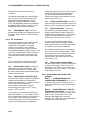
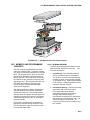
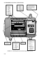
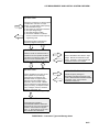
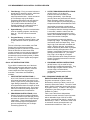
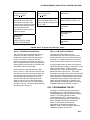
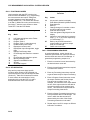
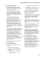
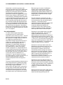
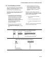
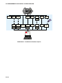
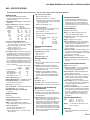
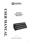
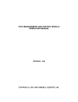
CR7 MEASUREMENT AND CONTROL SYSTEM OVERVIEW
The CR7 Measurement and Control System combines precision measurement with processing and
control capability in a battery operated system.
Campbell Scientific, Inc. provides three documents to aid in understanding and operating the CR7:
1. This Overview
2. The CR7 Operator's Manual
3. The CR7 Prompt Sheet
This Overview introduces the concepts required to take advantage of the CR7's capabilities. Hands-on
programming examples start in Section OV4. Working with a CR7 will help the learning process, so
don't just read the examples, turn on the CR7 and do them. If you want to start this minute, go ahead
and try the examples, then come back and read the rest of the Overview.
The sections of the Operator's Manual which should be read to complete a basic understanding of the
CR7 operation are the Programming Sections 1-3, the portions of the data retrieval Sections 4 and 5
appropriate to the method(s) you are using (see OV5), and Section 14 which covers installation and
maintenance.
Section 6 covers the details of serial communications. Sections 7 and 8 contain programming examples.
Sections 9-12 have detailed descriptions of the programming instructions, and Section 13 goes into
detail on the CR7 measurement procedures.
The Prompt Sheet is an abbreviated description of the programming instructions. Once familiar with the
CR7, it is possible to program it using only the Prompt Sheet as a reference, consulting the manual if
further detail is needed.
Read the Selected Operating Details and Cautionary Notes at the front of the Manual before using the
CR7.
OV1. PHYSICAL DESCRIPTION
The CR7 features a modular, multiple
processor design that provides precision
measurement and control capability in a rugged,
battery operated system. Control Module
functions include real-time task initiation,
measurement processing, data storage,
telecommunications, and keyboard/display
interaction. The I/O Module performs all analog
and pulse signal measurement functions as well
as the analog and digital control output
functions. The I/O Module contains its own
processor card, a precision analog interface
card, and seven card slots which can
accommodate any combination of I/O Cards.
Sensor leads are connected to the I/O cards via
screw terminals.
A maximum of four I/O modules, separated by
up to 1,000 feet, may be connected to a single
Control Module in applications that require
distributed measurement capability.
OV1.1 700X CONTROL MODULE
Contains the CPU card, with 24K of system
PROM and 40K of RAM; the serial interface
card for peripheral communication and
connection of up to four I/O Modules; and the
keyboard display card. Two slots are present
for optional RAM expansion. The system's 2.5
Ahr lead-acid batteries and AC charging
circuitry are also contained in this module.
The CS I/O 9-pin port provides connection to
data storage peripherals, such as the
SM192/716 Storage Module, and provides
serial communication to computer or modem
devices for data transfer or remote
programming (Section 6). This 9 pin port does
NOT have the same pin configuration as the
OV-1
CR7 MEASUREMENT AND CONTROL SYSTEM OVERVIEW
RS232 9 pin serial ports used on many
computers.
The SDM terminals adjacent to the serial port
allow connection to Synchronous Device for
Measurement (SDM) peripherals. These
peripherals include the SDM-INT8 Interval
Timer, the SDM-SW8A Switch Closure Module,
the SDM-CD16AC AC/DC Controller, and the
SDM-OBDII Engine Controller Interface.
709
512K MEMORY CARD: This card
provides RAM storage for an additional 262,126
Final Data values. Only one 709 card may be
installed.
voltage with respect to the CR7 ground. Singleended channels are numbered sequentially,
e.g., the HI and LOW sides of differential
channels 2 are single-ended channels 3 and 4,
respectively (Section 13.2).
724
PULSE COUNTER CARD: Provides 4
pulse counting channels for switch closures, low
level AC cycles, or high frequency pulse signals.
725
EXCITATION CARD: There are 8
switched analog excitation channels. These
supply programmable excitation voltages for
resistive bridge measurements. The excitation
channels are only switched on during the
measurement. Only one is on at a time.
OV1.2 720 I/O MODULE
The processor card provides regulated power
for analog and digital functions from the
unregulated 12 volt supply. The analog
interface card contains a 16-bit A/D-D/A
converter, and a precision voltage reference.
The standard I/O Module contains slots for 7 I/O
Cards; the expanded Model 720XL contains 14
slots. All input and output connections to the
I/O module are transient protected with spark
gaps.
The +12 volt and ground terminals provide a
direct connection to the CR7 power supply.
723
ANALOG INPUT CARD: Contains 14
differential or 28 single ended inputs. Input
ground terminals connect to a heavy copper
bar, which reduces single ended measurement
offsets to less than 5µV.
723-T ANALOG INPUT CARD WITH RTD:
Identical to the 723 Card except that a platinum
resistance thermometer is mounted in the
center of the terminal strip. The PRT provides a
reference junction temperature for
thermocouple measurement. The PRT
measurement is accurate to ±0.1oC over a
range of -40oC to +60oC.
The numbering on the terminals refers to the
differential channels; i.e., the voltage on the HI
input is measured with respect to the voltage on
the Low input. When making single-ended
measurements either the HI or the Low channel
may be used independently to measure the
OV-2
The two Continuous Analog Output (CAO)
channels supply continuous output voltages,
under program control, for use with strip charts,
X-Y plotters, or proportional controllers.
The 8 Digital Control Ports (0 or 5 volt states)
allow on-off control of external devices. These
control ports have a very limited current output
(5mA) and are used to switch solid state
devices which in turn provide power to relay
coils (Section 14.4).
726
50 VOLT ANALOG INPUT CARD:
Provides 8 differential or 16 single ended inputs
for full scale DC ranges of ±50 V and ±15V.
Resolution is 1.66 millivolts on the ±50 V and
0.5 millivolts on the ±15 V range. The common
mode range is ±50 volts.
OV1.3 ENCLOSURES AND CONNECTOR
OPTIONS
ENC-7L
ALUMINUM FRAME FOR
LABORATORY ENVIRONMENTS: 17" x 12" x
6"; provides a housing for benchtop use or a
frame for attachment to a wall or a NEMA type
enclosure.
ENC-7F
ENVIRONMENTALLY SEALED
FIBERGLASS ENCLOSURE: 20" x 13" x 10";
housing for harsh environments. Sensor leads
enter via two ports fitted with 0.75" conduit
bushings, and plugged with removable
stoppers. The 1.040" hole size accommodates
#14 shell size circular connectors.
CR
7
CR7 MEASUREMENT AND CONTROL SYSTEM OVERVIEW
F
LIE
RE
CA
E
LV
VA
UT
PR
UN
IO
N
ON
TT
S BU
RE
SE
FO
CA
G
IN
CK
ES
BE
LO
FIGURE OV1-1. CR7 Measurement and Control System
OV2. MEMORY AND PROGRAMMING
CONCEPTS
The CR7 must be programmed before it will
make any measurements. A program consists
of a group of instructions entered into a program
table. The program table is given an execution
interval which determines how frequently that
table is executed. When the table is executed,
the instructions are executed in sequence from
beginning to end. After executing the table, the
CR7 waits the remainder of the execution
interval and then executes the table again
starting at the beginning.
The interval at which the table is executed will
generally determine the interval at which the
sensors are measured. The interval at which
data are stored is separate and may range from
samples every execution interval to processed
summaries output hourly, daily, or on longer or
irregular intervals.
Figure OV2-1 represents the measurement,
processing, and data storage sequence in the
CR7 and shows the types of instructions used
to accomplish these tasks.
OV2.1 INTERNAL MEMORY
The CR7 has 40,960 bytes of Random Access
Memory (RAM), divided into five areas. The
five areas of RAM are:
1. Input Storage - Input Storage holds the
results of measurements or calculations.
The *6 Mode is used to view Input Storage
locations to check current sensor readings
or calculated values. Input Storage defaults
to 28 locations. Additional locations can be
assigned using the *A Mode.
2. Intermediate Storage - Certain Processing
Instructions and most of the Output
Processing Instructions maintain
intermediate results in Intermediate
Storage. Intermediate storage is
automatically accessed by the Instructions
and cannot be accessed by the user. The
default allocation is 64 locations. The
number of locations can be changed using
the *A Mode.
OV-3
CR7 MEASUREMENT AND CONTROL SYSTEM OVERVIEW
ANALOG IPUTS
SDM PORTS
Input/Output Instructions
1. Volt (SE)
2. Volt (DIFF)
4. Ex-Del-Se
5. AC Half Br
6. Full Br
7. 3W Half Br
9. Full Br-Mex
11. Temp (107)
12. RH-(07)
13. Temp-TC SE
14. Temp-TC DIFF
17. Temp-Panel
101
102
103
104
113
115
118
CS I/O PORT
SDM-INT8
SDM-SW8
SDM-AO4
SDM-CD16
SDM-SIO4
Set SDM Clock
SDM-OBDII
Telecommunications
Program Control Instructions
96 (Storage Module, Printer)
97 Initiate Telecommunications
98 Print Character
C1
700X CONTROL MODULE
C3
I/O MODULE
+12
720
C2
+12
MADE IN USA
SDM
CAMPBELL
SCIENTIFIC
INC. LOGAN, UTAH
SERIAL I/O
ANALOG INTERFACE
726
50 VOLT INPUT
1
H
2
H
3
H
1
H L
2
H L
3
H L
4
H L
5
H L
6
H L
7
H L
8
H L
1
CR7
4
MEASUREMENT & CONTROL SYSTEM
2
H
724
PULSE
COUNTER
I. D.
RTD
1
H L
1
2
H L
2
3
H L
4
H L
5
H L
SWITCHED ANALOG OUT
3
4
5
6
7
6
H L
8
1
7
H L
8
H L
9
H L
10
H L
CONTINUOUS ANALOG OUT
2
11
H L
12
H L
13
H L
14
H L
DIGITAL CONTROL OUT
1 2 3 4
5 6 7 8
725
EXCITATION
DATA
3
4
ON
1
2
3
A
4
5
6
B
7
8
9
C
*
0
#
D
AUX.
POWER
OFF
MADE IN USA
CONTROL PORTS
PULSE INPUTS
EXCITATION OUTPUTS
CAO
Input/Output Instructions
3. Pulse
Input/Output Instructions
4. Ex-Del-Se
5. AC Half Br
6. Full Br
7. 3W Half Br
9. Full Br-Mex
11. Temp (107)
12. RH (207)
22. Excit-Del
21ANALOG OUT
Input/Output Instructions
20 Set Port
Program Control Instructions
83 If Case < F
86 Do
88 If x < = > y
89 If x < = > f
91 If flag, port
92 If Time
Command Codes:
4x Set port x high
5x Set port x low
6x Toggle port x
7x Pulse port x
FIGURE OV1-2. CR7 Wiring Panel and Associated Programming Instructions
OV-4
CR7 MEASUREMENT AND CONTROL SYSTEM OVERVIEW
INPUT/OUTPUT
INSTRUCTIONS
Specify the conversion of a sensor signal
to a data value and store it in Input
Storage. Programmable entries specify:
(1) the measurement type
(2) the number of channels to measure
(3) the input voltage range
(4) the Input Storage Location
(5) the sensor calibration constants
used to convert the sensor output to
engineering units
I/O Instructions also control analog
outputs and digital control ports.
INPUT STORAGE
PROCESSING INSTRUCTIONS
Holds the results of measurements or
calculations in user specified locations.
The value in a location is written over
each time a new measurement or
calculation stores data to the locations.
Perform calculations with values in Input
Storage. Results are returned to Input
Storage. Arithmetic, transcendental and
polynomial functions are included.
OUTPUT PROCESSING
INSTRUCTIONS
INTERMEDIATE STORAGE
Perform calculations over time on the
values updated in Input Storage.
Summaries for Final Storage are
generated when a Program Control
Instruction sets the Output Flag in
response to time or events. Results
may be redirected to Input Storage for
further processing. Examples include
sums, averages, max/min, standard
deviation, histograms, etc.
Provides temporary storage for
intermediate calculations required by the
OUTPUT PROCESSING INSTRUCTIONS;
for example, sums, cross products,
comparative values, etc.
Output Flag set high
FINAL STORAGE
Final results from OUTPUT
PROCESSING INSTRUCTIONS are
stored here for on-line or interrogated
transfer to external devices (Figure
OV5.1-1). When memory is full, new
data overwrites the oldest data.
FIGURE OV2-1. Instruction Types and Storage Areas
OV-5
CR7 MEASUREMENT AND CONTROL SYSTEM OVERVIEW
3. Final Storage - Final, processed values are
stored here for transfer to printer, solid state
Storage Module or for retrieval via
telecommunication links. Values are stored
in Final Storage only by the Output
Processing Instructions and only when the
Output Flag is set in the users program.
The 18,336 locations allocated to Final
Storage at power up is reduced if Input or
Intermediate Storage is increased.
4. System Memory - used for overhead tasks
such as compiling programs, transferring
data, etc. The user cannot access this
memory.
5. Program Memory - available for user
programs entered in Program Tables 1 and
2, and Subroutine Table 3. (Sections OV3,
1.1)
The use of the Input, Intermediate, and Final
Storage in the measurement and data
processing sequence is shown in Figure OV2-1.
While the total size of these three areas
remains constant, memory may be reallocated
between the areas to accommodate different
measurement and processing needs (*A Mode,
Section 1.5). The size of system and program
memory are fixed.
OV2.2 CR7 INSTRUCTION TYPES
Figure OV2.1 illustrates the use of the three
different instruction types which act on data.
The fourth type, Program Control, is used to
control output times and vary program
execution. Instructions are identified by
numbers.
1. INPUT/OUTPUT INSTRUCTIONS (126,101-104, Section 9) control the terminal
strip inputs and outputs (the sensor is the
source, Figure OV1-2), storing the results in
Input Storage (destination). Multiplier and
offset parameters allow conversion of linear
signals into engineering units. The Control
Ports and Continuous Analog Outputs are
also addressed with I/O Instructions.
2. PROCESSING INSTRUCTIONS (30-66,
Section 10) perform numerical operations
on values located in Input Storage (source)
and store the results back in Input Storage
(destination). These instructions can be
used to develop high level algorithms to
process measurements prior to Output
Processing (Section 10).
OV-6
3. OUTPUT PROCESSING INSTRUCTIONS
(69-82, Section 11) are the only
instructions which store data in Final
Storage (destination). Input Storage
(source) values are processed over time to
obtain averages, maxima, minima, etc.
There are two types of processing done by
Output Instructions: Intermediate and Final.
Intermediate processing normally takes
place each time the instruction is executed.
For example, when the Average Instruction
is executed, it adds the values from the
input locations being averaged to running
totals in Intermediate Storage. It also keeps
track of the number of samples.
Final processing occurs only when the
Output Flag is high. The Output Processing
Instructions check the Output Flag. If the
flag is high, final values are calculated and
output. With the Average, accumulated
totals are divided by the number of samples
and the resulting averages sent to Final
Storage. Intermediate locations are zeroed
and the process starts over. The Output
Flag, Flag 0, is set high by a Program
Control Instruction which must precede the
Output Processing Instructions in the user
entered program.
4. PROGRAM CONTROL INSTRUCTIONS
(85-98, Section 12) are used for logic
decisions and conditional statements. They
can set flags, compare values or times,
execute loops, call subroutines,
conditionally execute portions of the
program, etc.
OV2.3 PROGRAM TABLES AND THE
EXECUTION AND OUTPUT INTERVALS
Programs are entered in Tables 1 and 2.
Subroutines, called from Tables 1 and 2, are
entered in Subroutine Table 3. The size of each
table is flexible, limited only by the total amount
of program memory. If Table 1 is the only table
programmed, the entire program memory is
available for Table 1.
Table 1 and Table 2 have independent
execution intervals, entered in units of seconds
with an allowable range of 0.0125 to 6553
seconds. Intervals shorter than 0.1 seconds are
allowed only in Table 1. Subroutine Table 3 has
no execution interval; subroutines are only
executed when called from Table 1 or 2.
CR7 MEASUREMENT AND CONTROL SYSTEM OVERVIEW
Table 1.
Execute every x sec.
0.0125 < x < 6553
Table 2.
Execute every y sec.
0.1 < y < 6553
Table 3.
Subroutines
Instructions are executed
sequentially in the order they
are entered in the table. One
complete pass through the table
is made each execution interval
unless program control
instructions are used to loop or
branch execution.
Table 2 is used if there is a
need to measure and process
data on a separate interval from
that in Table 1.
A subroutine is executed only
when called from Table 1 or 2.
Normal Order:
MEASURE
PROCESS
CHECK OUTPUT COND.
OUTPUT PROCESSING
Subroutine Label
Instructions
End
Subroutine Label
Instructions
End
Subroutine Label
Instructions
End
FIGURE OV2-2. Program and Subroutine Tables
OV2.3.1 THE EXECUTION INTERVAL
OV2.3.2 THE OUTPUT INTERVAL
The execution interval specifies how often the
program in the table is executed, which is
usually determined by how often the sensors
are to be measured. Unless two different
measurement rates are needed, use only one
table. A program table is executed sequentially
starting with the first instruction in the table and
proceeding to the end of the table.
The interval at which output occurs is
independent from the execution interval, other
than the fact that it must occur when the table is
executed (i.e., a table cannot have a 10 minute
execution interval and output every 15 minutes).
Each instruction in the table requires a finite
time to execute. If the execution interval is less
than the time required to process the table, the
CR7 overruns the execution interval, finishes
processing the table and waits for the next
execution interval before initiating the table.
When an overrun occurs, decimal points are
shown on either side of the G on the display in
the LOG mode (*0). Overruns and table priority
are discussed in Section 1.1.
A single program table can have many different
output intervals and conditions, each with a unique
data set (output array). Program Control
Instructions are used to set the Output Flag which
determines when output occurs. The Output
Processing Instructions which follow the instruction
setting the Output Flag determine the data output
and its sequence. Each additional output array is
created by another Program Control Instruction
setting the Output Flag high in response to an
output condition, followed by Output Processing
Instructions defining the data set to output.
OV3. PROGRAMMING THE CR7
A program is created by keying it directly into
the datalogger or on a PC using the PC208 or
PC208W Datalogger Support Software program
EDLOG. This manual describes direct
interaction with the CR7. Work through the
direct programming examples in this overview
before using EDLOG and you will have the
basics of CR7 operation as well as an
appreciation for the help provided by the
software. Section OV3.5 describes options for
loading the program into the CR7.
OV-7
CR7 MEASUREMENT AND CONTROL SYSTEM OVERVIEW
OV3.1 FUNCTIONAL MODES
User interaction with the CR7 is broken into
different functional MODES, (e.g., programming
the measurements and output, setting time,
manually initiating a block data transfer to
Storage Module, etc.). The modes are referred
to as Star (*) Modes since they are accessed by
first keying *, then the mode number or letter.
Table OV3.1 lists the CR7 Modes.
TABLE OV3-1. * Mode Summary
Key
Mode
*0
*1
*2
*3
*4
*5
*6
LOG data and indicate active Tables
Program Table 1
Program Table 2
Program Table 3, subroutines only
Enable/disable printer output
Display/set real time clock
Display/alter Input Storage data, toggle
flags
Display Final Storage data
Final Storage data transfer to cassette
tape
Final Storage data transfer to printer
Memory allocation/reset
Signature test/PROM version
Security
Save/load Program
TABLE OV3-2. Key Description/Editing
Functions
Key
Action
0-9
*
A
B
C
Key numeric entries into display
Enter Mode (followed by Mode Number)
Enter/Advance
Back up
Change the sign of a number or index
an input location to loop counter
Enter the decimal point
Clear the rightmost digit keyed into the
display
Advance to next instruction in program
table (*1, *2, *3) or to next output array
in Final Storage (*7)
Back up to previous instruction in
program table or to previous output
array in Final Storage
Delete entire instruction
D
#
#A
*7
*8
*9
*A
*B
*C
*D
OV3.2 KEY DEFINITION
Keys and key sequences have specific
functions when using the CR7 keyboard or a
terminal/computer in the remote keyboard state
(Section 5). Table OV3.2 lists these functions.
In some cases, the exact action of a key
depends on the mode the CR7 is in and is
described with the mode in the manual.
#B
#D
OV3.3 PROGRAMMING SEQUENCE
In routine applications, sensor signals are
measured, processed over some time interval,
and the results are stored in Final Storage. A
generalized programming sequence is:
1. Enter the execution interval, determined by
the desired sensor scan rate.
2. Enter the Input/Output Instructions required
to measure the sensors.
3. Enter any Processing Instructions required
to get the data ready for Output Processing.
4. Enter a Program Control Instruction to test
the output condition and Set the Output
Flag when the condition is met. For
example, use Instruction 92 to output based
on time, 86 to output each time the table is
executed, and 88 or 89 to compare input
values. This instruction must precede the
Output Processing Instructions.
5. Enter the Output Processing Instructions to
store processed data in Final Storage. The
order in which the data are stored is
determined by the order of the Output
Processing Instructions in the table.
6. Repeat steps 4 and 5 for output on different
intervals or conditions.
OV-8
CR7 MEASUREMENT AND CONTROL SYSTEM OVERVIEW
OV3.4 INSTRUCTION FORMAT
Instructions are identified by an instruction
number. Each instruction has a number of
parameters that give the CR7 the information it
needs to execute the instruction.
The CR7 Prompt Sheet has the instruction
numbers in red, with the parameters briefly
listed in columns following the description.
Some parameters are footnoted with further
description under the "Instruction Option Codes"
heading.
For example, Instruction 73 stores the
maximum value that occurred in an Input
Storage Location over the output interval. The
instruction has three parameters (1)
REPetitionS, the number of sequential Input
Storage locations on which to find maxima, (2)
TIME, an option of storing the time of
occurrence with the maximum value, and (3)
LOC the first Input Storage Location operated
on by the Maximum Instruction. The codes for
the TIME parameter are listed in the "Instruction
Option Codes".
The repetitions parameter specifies how many
times an instruction's function is to be repeated.
For example, four 107 thermistor probes, wired
to single-ended channels 1 through 4, are
measured using a single Instruction 11, Temp107, with four repetitions. Parameter 2
specifies the input channel of the first thermistor
(channel 1) and parameter 4 specifies the Input
Storage Location in which to store
measurements from the first thermistor. If
Location 5 were used, the temperature of the
thermistor on channel 1 would be stored in Input
Location 5, the temperature from channel 2 in
Input Location 6, etc.
Detailed descriptions of the instructions are
given in Sections 9-12.
OV3.5 ENTERING A PROGRAM
Programs are entered into the CR7 in one of
four ways:
b. Stored/loaded from SM192/716 Storage
Module
3. Loaded from Storage Module or internal
PROM (special software) upon power-up.
A program is created by keying it directly into
the datalogger as described in the following
Section, or on a PC using the PC208
Datalogger Support Software.
PC208 Software programs are used to develop
and send programs to the CR7. Program files
developed can be downloaded directly to the
CR7 via direct wire, telephone, or Radio
Frequency (RF).
Programs on disk can be copied to a Storage
Module. Using the *D Mode to save or load a
program from a Storage Module is described in
Section 1.8.
If the SM192/716 Storage Module is connected
when the CR7 is powered-up, the CR7 will
automatically load program number 8, provided
that a program 8 is loaded in the Storage
Module (Section 1.8).
It is also possible (with special software) to
create a PROM (Programmable Read Only
Memory) that contains a datalogger program.
With this PROM installed in the datalogger, the
program will automatically be loaded and run
when the datalogger is powered-up, requiring
only that the clock be set.
OV4. PROGRAMMING EXAMPLE
The best way to become acquainted with the
CR7 is to program it and make some
measurements. If your CR7 contains either a
723 or 723-T Analog Input card, a short
copper-constantan thermocouple (TC) should
be connected to channel 5. In this example, you
will program the CR7 to sample the
thermocouple temperature. If you have not
purchased the 723-T with a Resistive
Temperature Device (RTD) to measure the TC
reference junction temperature, a "dummy"
reference temperature will be used.
1. Keyed in using the CR7 keyboard.
2. Loaded from a pre-recorded listing using
the *D Mode. There are two types of
storage/input:
a. Stored on disk/sent from computer
(PC208 software).
OV-9
CR7 MEASUREMENT AND CONTROL SYSTEM OVERVIEW
Tables OV3-1 and OV3-2 summarize the
Keyboard Commands and Control Modes used
to program the CR7, monitor Input and Final
Storage and control data output to peripherals.
The instructions, and their associated
parameters, are the CR7's programming steps
and are used to build the CR7's program. It is
not necessary to understand all the commands
to proceed with this programming exercise. It is
helpful to find the example's instructions on the
CR7 Prompt Sheet provided with this manual.
As you become familiar with programming the
CR7, you will find that the Prompt Sheet or the
PC208 program EDLOG has all the information
you need to write your program. By following
along on the Prompt Sheet as you proceed with
this exercise, you will learn how to use it to write
your own programs.
OV4.1 MEASUREMENT
To make a thermocouple temperature
measurement, the CR7 must know the
temperature of the reference junction. The CR7
takes the reference temperature, converts it to
the equivalent TC voltage, adds the measured
TC voltage and converts the sum to
temperature through a polynomial fit to the TC
output curve. In this example, the reference
junction is at the Analog Input Card. Its
temperature is measured with Instruction 17,
Panel Temperature. If you have an Analog
Input Card with RTD, check to see which
number is assigned to it. A tag labeled RTD is
on the left hand side and the card number is on
the right hand side of the Analog Input Card. If
the RTD card is not card 1, you must enter the
correct card number as Parameter 1 of
Instruction 17. If you do not have an Analog
Input Card with RTD, you will omit Instruction 17
from the Program and enter a "dummy"
reference temperature after the Program is
compiled.
The thermocouple temperature measurement is
made using Instruction 14 (differential voltage
measurement of TC) on differential channel 5.
When using a copper-constantan
thermocouple, the copper lead is connected to
the high input of a differential channel and the
constantan lead is connected to the low side.
The channel numbering printed on the Analog
Input Cards refers only to differential channels.
OV-10
Either the high or low side of a differential
channel may be used for single ended
measurements. (Each side is counted when
assigning single ended channel numbers; e.g.,
the high side of differential channel 8 is single
ended channel 15 and the low side is single
ended channel 16).
The first parameter in Instruction 14 is the
number of times to repeat the measurement: 1
is entered because only one thermocouple is
measured. If more thermocouple
measurements were desired, the copper leads
would be connected to the high sides of
consecutive differential channels, the
constantan leads to the low sides and the
number of repetitions entered in Parameter 1
would equal the number of thermocouples.
Parameter 2 is the voltage range to use when
making the measurement. The output of a
copper-constantan thermocouple is
approximately 40 microvolts per oC difference
in temperature between the two junctions. The
+5000 uV scale will provide a range of +5000/40
= +125 oC (i.e., this scale will not overrange as
long as the measuring junction is within 125 oC
of the panel temperature). The resolution of the
+5000 uV range is 166 nV or 0.004 oC.
Parameter 3 is the Input Card number and
Parameter 4 is the channel on which to make
the first measurement. If more than one
thermocouple is measured, the CR7 will
automatically advance through the channels
and on to the next card if necessary. Similarly,
Parameter 7 is the Input Storage Location in
which to store the first measurement; e.g., if
there are five repetitions and the first
measurement is stored in location 3, the final
measurement will be stored in location 7.
Parameter 6 is the Input Storage location in
which the reference temperature is stored, and
Parameters 8 and 9 are the multiplier and offset
to apply to the temperature value. A multiplier of
1 and an offset of 0 give the result in oC, a
multiplier of 1.8 and an offset of 32 give the
result in oF.
Now that you have some idea of what you are
telling the CR7 by entering the parameters, we
will proceed with programming the CR7.
CR7 MEASUREMENT AND CONTROL SYSTEM OVERVIEW
TABLE OV4-1. Thermocouple Measurement Programming Example
TURN ON THE POWER SWITCH AND PROCEED AS FOLLOWS:
Display
ID:Data
Key
HELLO 01
Display
ID:Data
Key
:0064
*
00:00
1
01:00
A
01:0.0000
2
01:2
A
Description
The number after "HELLO" will count up as memory
is checked. If you have a 512K Memory Card, this
can take a long time; key # to abort the test. The
result of the CPU board memory check is then
displayed (Sect. 1.5)
Enter Program Table 1, advance to Execution
Interval
Enter 2 second Execution Interval advance to first
instruction
-------Users without RTD omit next Instruction-----01:P00
01:00
17
1
02:0000
1
01:P17
01:1
A
A
02:1
A
Measure Panel Temp., advance to first Parameter
RTD in input card #1, if RTD card other than #1,
enter correct card #
Store temp in location 1
-------Users without RTD continue here------Instruction Location Number will be 1 less (i.e., 01:P00)
02:P00
01:00
02:00
03:00
04:00
05:00
06:0000
07:0000
08: 0.0000
09: 0.0000
14
1
2
1
5
1
1
2
1
02:P14
01:1
02:2
03:1
04:5
05:1
06:1
07:2
08:1
09:0.0000
03:P00
00:00
A
A
A
A
A
A
A
A
A
A
*
0
:LOG 1
TC temp., differential meas.
1 repetition
Range code (5000uV, slow)
Input card #1
Input channel of 1st TC
TC type (copper-constantan)
Reference temp. is in location 1
Store TC temp. in location 2
Multiplier of 1
No offset entered (offset=0), advance to next
instruction
Exit Table 1
Enter *0 Mode, compile table
The CR7 is now programmed to measure the thermocouple temperature and to store the result in Input
Storage Location 2. The colon between the ID and Data fields blinks each time Table 1 is executed,
every 2 seconds in this example. If you do not have an RTD, the "reference temperature" is 0.0 and the
value stored in Location 2 is the difference in temperature between the panel and the thermocouple. The
*6 Mode can be used to monitor the values in the Input Storage and to change the value of the dummy
reference temperature.
OV-11
CR7 MEASUREMENT AND CONTROL SYSTEM OVERVIEW
TABLE OV4-2. Using *6 Mode to Observe Example TC Measurements
(User with Model 723-T RTD Card)
Display
ID:Data
Key
:LOG 1
*6
00:00
0
Display
ID:Data
06:0000
01:21.234
02:22.433
01:21.199
:LOG 1
Key
A
A
B
*
Description
Enter *6 Mode, advance to first location
Panel temp is 21.234 oC, advance to location 2
TC temp is 22.433 oC, backup to location 1
Panel temp is now 21.199 oC
Return to *0 Mode
TABLE OV4-3. Using *6 Mode to Observe Example TC Measurements
(User with Model 723 Card, No RTD)
Display
ID:Data
Key
:LOG 1
*6
:0.0000
20
00:00
0
Display
ID:Data
06:0000
01:0.0000
02:2.9533
01:0.0000
:20
01:20.000
02:22.866
Key
A
A
B
C
A
A
*
:LOG 1
You can advance through Input Storage by
keying in the advance command, A, or backup
by keying in the backup command, B. The Input
Location you are observing is shown on the left
in the display ID field. The temperature data
stored in the Input locations are updated every 2
seconds, each time Table 1 is executed. Verify
this by changing the temperature of the
thermocouple (hold it in your fingers) while
monitoring the proper Input Location.
OV-12
Description
Enter *6 Mode, advance to first location
Reference temp is 0.0oC, advance to location 2
TC "temp" is 2.9533 C, backup to location 1
Setup to change stored value
Store 20 in location 1
Advance to location 2
The TC temp in location 2 using a reference
temperature of 20o
Return to *0 Mode
It is possible to go directly to a specific Input
Storage location by entering the *6 Mode and
keying in the desired location before keying A.
A similar utility is available in other Modes.
OV4.2 OUTPUT
In the following example instructions are
appended to Table 1 to output the time and the
average temperatures to Final Storage every 5
minutes.
CR7 MEASUREMENT AND CONTROL SYSTEM OVERVIEW
TABLE OV4-4. Example Programming to Obtain Five Minute Averages
Display
ID:Data
Key
Display
ID:Data
1
3
: LOG 1
01:00
01:3
A
03:P00
01:0000
02:0000
03:00
92
0
5
10
03:P92
01:0
02:5
03:10
A
A
A
A
Enter If Time Instruction
Enter 0 minutes into interval
Enter 5 minute time interval
Set output Flag 0
04:P00
01:0000
05:P00
01:00
02:0000
77
10
71
2
1
04:P77
:10
05:P71
01:2
02:1
A
A
A
A
A
Enter Output Time Instruction
Code for HR:MIN
Enter Average Instruction
2 repetitions
Location of 1st input data to be averaged
*
Exit Table 1
Enter *5 Mode to set clock (the clock will be running)
Enter Year
Enter Julian day (January 11 assumed in this
example)
Enter Hours:Minutes (24 hour time, 1:24 PM
assumed in this example)
Exit *5 Mode, compile Table 1, commence logging
data
00:00
01:00
06:P00
Key
*
00:00
05:00
05:0000
5
85
11
:00:21:32
05:85
05:11
A
A
A
05:00:21
1324
05:13:24
A
13:24:01
Description
*0
Program Table 1
Advance to 3rd Instruction location (Key in 2 if
Instruction 17 was not entered, Instruction Location
Number will be 1 less than shown in table)
: LOG 1
The CR7 is now programmed to sample the panel and thermocouple temperatures every 2 seconds and
to output the time and the average temperatures to Final Storage every 5 minutes. Each Output Array
sent to Final Storage will consist of 4 data values. The first value will be an output identifier which gives
the number of the Table which caused the output, and the instruction location number of the instruction
which set the output flag. The second value will be the time, and the third and fourth values will be the
average temperatures of the I/O Module and the thermocouple. Values stored in Final Storage can be
viewed using the *7 Mode. Table 1.2-5 shows an example of the use of the *7 Mode, it is assumed that
the CR7 has been logging data for 8 minutes since the time was set in the previous example.
OV-13
CR7 MEASUREMENT AND CONTROL SYSTEM OVERVIEW
TABLE OV4-5. Using *7 Mode to View Values in Final Storage
Display
ID:Data
Key
Display
ID:Data
:LOG 1
00:00
Key
Description
*
7
07:9.0000
A
01:0103.
A
02:1325.
03:22.57
04:23.43
01:0103.
02:1330.
03:22.61
00:00
A
A
A
A
A
*
0
:LOG 1
Enter *7 Mode. The DSP is at Final Storage location 9,
advance to first data value
Output identifier: users who did not enter Instruction 17 will
see 01: 0102 because the output flag is set by the second
instruction in Table 1
Time
Average panel temp for readings between 1:24 and 1:25 P.M.
Average thermocouple temp.
Output identifier
Time
Average panel temp for readings between 1:25 and 1:30 P.M.
Enter *0 Mode
OV4.3 EDITING AN EXISTING PROGRAM
When editing an existing program in the CR7,
entering a new instruction inserts the
instruction; entering a new value for an
instruction parameter replaces the previous
value.
To insert an instruction, enter the program table
and advance to the position where the
instruction is to be inserted (i.e., P in the data
portion of the display), key in the instruction
number, and then key A. The new instruction
will be inserted at that point in the table,
advance through and enter the parameters.
The Instruction that was at that point and all
instructions following it will be pushed down to
follow the inserted instruction.
An instruction is deleted by advancing to the
instruction number (P in display) and keying #D
(Table OV3-2).
To change the value entered for a parameter,
advance to parameter and key in the correct
value then key A. Note that the new value is not
entered until A is keyed.
TABLE OV4-6. EDLOG Listing of Example
Program
*
01:
1
2
Table 1 Programs
Sec. Execution Interval
01:
01:
02:
P17
1
1
Panel Temperature
IN Card
Loc :
02:
01:
02:
03:
04:
05:
06:
07:
08:
09:
P14
1
2
1
5
1
1
2
1
0
Thermocouple Temp (DIFF)
Rep
5000 uV slow Range
IN Card
IN Chan
Type T (Copper-Constantan)
Ref Temp Loc
Loc [:TC Temp ]
Mult
Offset
03:
01:
02:
03:
P92
0
5
10
If time is
minutes into a
minute interval
Set high Flag 0 (output)
04:
01:
P77
10
Real Time
Hour-Minute
05:
01:
02:
P71
2
1
Average
Reps
Loc
OV4.4 EDLOG PROGRAM LISTING
The examples in the rest of this manual use
program listings generated by EDLOG, the
datalogger Program Editor for the PC
(PC208(W) Software). The EDLOG listing does
not show the CR7 display or the "A" keystrokes
used to enter data. The EDLOG listing for the
previous example is given in Table OV4-6.
OV-14
CR7 MEASUREMENT AND CONTROL SYSTEM OVERVIEW
OV5. DATA RETRIEVAL OPTIONS
There are several options for data storage and
retrieval. These options are covered in detail in
Sections 2, 4, and 5. Figure OV5-1
summarizes the various possible methods.
Regardless of the method used, there are three
general approaches to retrieving data from a
datalogger.
1. On-line output of Final Storage data to a
peripheral storage device. On a regular
schedule, that storage device is brought
back to the office/lab where the data is
transferred to the computer. Another
storage device is usually taken into the field
and exchanged for the one which is
retrieved so that data collection can
continue uninterrupted.
2. Bring a storage device to the datalogger
and transfer all the data that has
accumulated in Final Storage since the last
visit.
3. Retrieve the data over some form of
telecommunications link, that is, Radio
Frequency (RF), telephone, short haul
modem, multi-drop interface, or satellite.
The PC208 software automates this
process.
Regardless of which method is used, the
retrieval of data from the datalogger does NOT
erase those data from Final Storage. The data
remain in the ring memory until:
•
they are written over by new data
(Section 2.1)
•
memory is reallocated (Section 1.5)
•
the power to the datalogger is turned
off.
Table OV5-1 lists the instructions used with the
various methods of data retrieval.
TABLE OV5-1. Data Retrieval Methods and Related Instructions
Storage
Module
Printer, other
Serial Device
Telecommunications
(RF, Phone, Short Haul, SC32A)
Inst. 96,
*4
*9
*D
Inst. 96, 98
*4
*9
*D
Inst. 97
(Telecommunications Commands)
TABLE OV5-2. Data Retrieval Sections in Manual
Topic
Instr. 96
Instr. 97
*4
*8
*9
*D
Storage Module
Telecommunications
Section in Manual
4.1, 12
12
4.1
4.2
4.2
1.8
4.3
5
OV-15
CR7 MEASUREMENT AND CONTROL SYSTEM OVERVIEW
+12
720
I/O MODULE
700X CONTROL MODULE
MADE IN USA
CAMPBELL
SCIENTIFIC
INC. LOGAN, UTAH
SERIAL I/O
ANALOG INTERFACE
6
H L
7
H L
8
H L
1
2
3
4
5
6
7
8
9
H L
H L
H L
H L
H L
H L
H L
H L
H L
10
H L
11
H L
726
50 VOLT INPUT
1
H
2
H
3
H
1
H L
2
H L
3
H L
4
H L
5
H L
1
CR7
4
MEASUREMENT & CONTROL SYSTEM
2
H
724
PULSE
COUNTER
I. D.
RTD
1
2
SWITCHED ANALOG OUT
3
4
5
6
7
13
H L
14
H L
4
725
EXCITATION
ON
OFF
Display
Storage
Module
Card Storage
Module
DATA
3
DIGITAL CONTROL OUT
1 2 3 4
5 6 7 8
CONTINUOUS ANALOG OUT
1
2
8
12
H L
Multidrop
Modem
1
2
3
A
4
5
6
B
7
8
9
C
*
0
#
D
AUX.
POWER
MADE IN USA
Shorthaul
Modem
RF Modem
Phone
Modem
Satellite
Interface
Phone
Modem
Satellite
Ground
Station
Transceiver
Storage
Module
Card Storage
Module
RS-232
Interface
RS-232
Interface
Direct
RS-232
Interface
Multidrop
Modem
Shorthaul
Modem
RS-232
Interface
Logger Time 00:03:54
Flags
Ports
H=Help
Transceiver
RF Base
Station
V = View save to file
F1. . F8 = Toggle flags
P1. . P6 = Toggle ports
C = Collect data
G = Graph enter/exit
R = Re-scale
+ = Incr. auto exponent
- = Decr. auto exponent
1: SOLAR
2: TEMP C
3: RH %
2300
2200
2100
2000
1900
1800
900
800
700
1700
1600
1500
600
500
400
1400
1300
300
200
1200
1100
1000
100
Scale = Auto
FIGURE OV5-1. Data Retrieval Hardware Options
OV-16
CR7 MEASUREMENT AND CONTROL SYSTEM OVERVIEW
OV6. SPECIFICATIONS
Electrical specifications are valid for over a -25° to +50°C range unless otherwise specified.
Analog Inputs
(723T or 723 Card specifications below;
726 ±50 V Card specifications discussed in
System Description)
Voltage Measurement Types: Single-ended or
differential.
Range and Resolution: Ranges are software
selectable on any input channel.
Full Scale
Resolution
Input Range (mV)
Differential Single-ended
±5000
166
µV
333
µV
±1500
50
µV
100
µV
±500
16.6 µV
33.3 µV
±150
5
µV
10
µV
±50
1.66 µV
3.33 µV
±15
500
nV 1000
nV
±5
166
nV
333
nV
±1.5
50
nV
100
nV
Accuracy of Voltage Measurements:
Differential: ±0.02% FSR (±0.01%, 0-40°C)
(e.g. ±0.02% FSR = ±2.0 mV for ±5 V range)
Positive single-ended: ±0.02% FSR
(±0.01%, 0-40°C) ±5 µV
Negative single-ended: ±0.03% FSR
(±0.015%, 0-40°C) ±5 µV
High Frequency Pulse Mode
Minimum Pulse Width: 2 µs
Maximum Input Frequency: 250 kHz
Voltage Thresholds: The count is incremented
when the input voltage changes from below
1.5 V to above 3.5 V.
Maximum Input Voltage: ±20 V
Low Level AC Mode
This mode is used for counting the frequency
of low voltage, sine wave signals.
Input Hysteresis: 11 mV
Maximum AC Input Voltage (RMS): 20 V
Frequency Range:
Minimum AC Input Voltage
(mV RMS)
15
25
50
160
Range (Hz)
1
1
1
1
to
to
to
to
100
1,000
3,000
10,000
Digital Control Outputs
(725 Card)
Each card includes 8 digital control outputs.
Transient Protection
All input and output connections to the I/O
Module are protected using spark gaps that
are rated to 10,000 A. The spark gaps are
connected directly to a heavy copper bar on
each input card with no more than 2 inches of
20 AWG copper wire.
Control Module
Processor: Hitachi 6303
Memory: 24K ROM; 40K RAM, 709 Card
provides an additional 512K RAM.
Data Storage: 18.8K values, standard; 280K
values, expanded.
Display: 8 digit LCD (0.5” digits).
Peripheral Interface: 9-pin, D-type connector
on the Control Module panel for connection to
storage module, card storage module,
multidrop interface, modem, printer, or RS-232
adapter. Baud rates selectable at 300, 1200,
9600, and 76,800.
Output Voltages (no load):
High: 5.0 V ±0.1 V
Low: < 0.1 V
I/O Module Interface: Optically isolated current
loops allow connection of up to 4 I/O Modules.
I/O Modules can be separated from the Control
Module by up to 1,000 feet.
Output Resistance: 400 Ω
Clock Accuracy: ±1 minute per month.
Analog Outputs
(725 Card)
Maximum Program Execution Rate: System
tasks can be initiated in sync with real-time up
to 80 Hz.
Each card contains 8 switched and 2 continuous
analog outputs.
System Power Requirements
Switched: Provides a precision voltage for
resistance measurement, then switches off
(high impedance). Only one switched output
can be active at a time.
Voltage: 9.6 to 15 VDC
Internal Batteries: Sealed rechargeable with
2.5 Ahr capacity per charge.
Common Mode Range: ±5 V
Continuous: A preset voltage is held until
updated. Voltage degrades 0.17 mV every 7
seconds. All continuous analog outputs (and
digital control ports) can be active simultaneously.
Common Mode Rejection: > 140 dB (DC to 100 Hz)
Range: ±5 V
Normal Mode Rejection: 70 dB (60 Hz with
slow differential measurement)
Accuracy: Same as voltage measurements.
Input Current: 100 pA max
Output Current: 25 mA at ±5 V, 50 mA at ±2 V
Input Sample Rates: Fast A/D conversions are
integrated over 250 µs. Slow A/D conversions
are integrated over 16.67 ms for 60 Hz AC
rejection or optionally, 20.0 ms for 50 Hz AC
rejection. Differential measurements include
two conversions, one with reversed input polarity, to reduce thermal offset and common mode
errors. The following intervals do not include
the self-calibration measurement which occurs
once per instruction.
Input sample Typical input
rates
noise
ms/channel
nV/RMS
Fast Single-ended
2.9
350
Fast Differential
4.7
250
Slow Single-ended
22.0
43
Slow Differential
43.0
30
Fast Differential (TC) 7.9
250
Input Current Noise: 9 pA RMS (slow differential)
Input Resistance: 2.5 GΩ typical
Sustained Input Voltage without Damage:
≤ ±16 VDC
Pulse Counters
(724 Card)
Pulse Counters per Card: 4
Maximum Counts per Interval: 32,767 (with
overrange detection)
Modes: Programmable modes are switch
closure, high frequency pulse, and low level AC.
Switch Closure Mode
Minimum Switch Closed Time: 1 ms
Minimum Switch Open Time: 4 ms
Maximum Bounce Time: 1.4 ms open without
being counted.
Resolution: 166 µV
Resistance and Conductivity
Measurements
(Combination of 723 and 725 Cards)
Accuracy: ±0.01% of full scale bridge output
provided the matching bridge resistors are not
the limiting factor.
Measurement Types: 6-wire and 4-wire full
bridge, 4-wire, 3-wire, and 2-wire half bridges.
High accuracy, low impedance bridge
measurements are made ratiometrically with
dual polarity measurements of excitation and
output to eliminate thermal emfs. AC resistance and conductivity measurements use a
750 µs excitation pulse with the signal integration occurring over the last 250 µs. An equal
duration pulse of opposite polarity is applied
for ionic depolarization.
Typical Current Drain: 3.5 - 6 mA (minimum
system) quiescent, 16 mA during processing,
100 mA during analog measurement.
Charging Circuit: Requires DC or rectified AC
voltage from 15 to 25 V. Thermal compensation is included to optimize charging voltage
according to ambient temperature.
External Batteries: Any 12 V external battery
can be a primary power source; internal batteries provide a backup while the external
batteries are changed.
Operation from AC Sources: An AC operated
battery charger is included with the enclosure
to maintain full charge on the batteries where
AC power is available. In the event of power
failure, the internal batteries will keep the
system operational for up to 5 days in most
applications.
Physical Specifications
Size:
ENC 7L
ENC 7F
ENC 7XL
17” x 12” x 6”
20” x 13” x 10”
19” x 19” x 10”
Weight:
~40 lbs (ENC 7F with 700X, 720, &
seven I/O cards).
Warranty
Three years against defects in materials and
workmanship.
OV-17