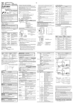
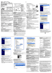
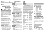
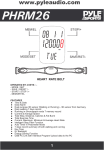
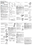
1
1. Reference manual
4. Product composition
Refer to the under mentioned manual for details about product installation, and programming.
4.1 Each part name
1)
FX2N-10GM
USER’S GUIDE
JY992D77701F
This manual only describes the specifications for FX2N-10GM positioning controller.
For complete operation, wiring, mounting and programming instructions please refer to the FX2N-10GM,
FX2N-20GM HARDWARE PROGRAMMING MANUAL, FX PROGRAMMING MANUAL ΙΙ and FX SERIES
HARDWARE MANUAL.
These manuals should be read and understood before attempting to install or use the unit.
And, store this manual in a safe place so that you can take it out and read it whenever necessary. Always
forward it to the end user.
FX 2N-10GM,
FX2N-20GM
HARDWARE PROGRAMMING MANUAL
The installation of FX2N-10GM and FX2N-20GM and wiring and the instructions are explained.
The name and description of each part of the FX2N-10GM are explained below.
➀ ➁➂ ➃
2) E-20TP-E OPERATION MANUAL
The operation of the input of the program which uses E-20TP-E and the monitor and the test is
explained.
POWER
READY
ERROR
CPU-E
AUTO
MANU
3) FX-PCS-VPS/WIN-E SOFTWARE MANUAL
The operation program is input using the FX-PCS-VPS/WIN-E software. This manual explains the
operation of the monitor and test functions.
4) FX-PCS-KIT-GM-EE SOFTWARE MANUAL
The program is input via the FX-PCS-KIT-GM-EE. The manual explains the operation of the monitor
and test functions.
START
STOP
ZRN
FWD
RVS
DOG
LSF
LSR
X0
X1
X2
X3
Y0
Y1
Y2
Y3
Y4
Y5
➄
FX2N-10GM
SVRDY
SVEND
PGO
FP
RP
CLR
➉
The manual in 1) is not included with the product. Please request from the shop where the units was purchased if required.
The manuals in 2), 3) and 4) are included with the product.
Accessories
Power supply cable
FX2NC-100MPCB 1
Connection cable
FX2N-GM-5EC 1
➅➈ ➇ ➆➅
➀Operation indicator LED
➁MANU/AUTO switch
➂Connector for programming tool
➃I/O display
➄Connector for PLC extension block
➅Hook for DIN rail installation
➆Connector for motor amplifier: CON2
➇Connector for I/O: CON1
➈Connector for power supply
➉Connector for PLC
4.2 Operation display
Safety Precaution (Read these precautions before use.)
2. Outline of the unit
This manual classifies the safety precautions into two categories:
and
.
Indicates that incorrect handling may cause hazardous conditions, resulting in death or
severe injury.
Indicates that incorrect handling may cause hazardous conditions, resulting in medium or
slight personal injury or physical damage.
Depending on the circumstances, procedures indicated by
It is important to follow all precautions for personal safety
may also cause severe injury.
DESIGN PRECAUTIONS
•
Install a safety circuit outside the PLC so that the entire system conservatively operates even if an
abnormality occurs in the external power supply or a failure occurs in the PLC.
If the safety circuit is installed inside the PLC, malfunction and erroneous output may cause
accidents.
The state of FX2N-10GM is displayed by LED.
The FX2N-10GM positioning controller (hereinafter call FX2N-10GM or 10GM) is a pulse chain output unit
that enables the positioning control of a stepping motor or a servo motor via the drive unit.
Name of LED
•
One FX2N-10GM can control 1 axis.
POWER
LED lights when power is supplied. If LED is not lit, check power supply voltage and
current.
•
Both dedicated positioning language (cod instructions) and sequence language (basic instructions
and application instructions) are available.
READY
LED lights when accepting an axis instruction.
During pulse output or when an error occurs, the LED is off.
A pulse generator can be connection.(The manual pulse generators must be an open collector output
type.)
ERROR
LED is lit or blinks when an error occurs in the positioning drive of FX2N-10GM.
CPU-E
CPU error. Incompatible system configuration, excess noise, etc. (Mixing foreign body,
and influence of noise, etc.)
•
•
The zero return operation at each start can be omitted with a servo amplifier with the absolute position
(ABS) detection function.
•
The FX2N-10GM can be used alone.
When an FX 2N-10GM is connected with an FX2N/FX2NC/FX3U/FX3UC series Programmable logic controller (here after call PLC), the positioning data can be read/written.
When connecting to an FX 2NC PLC, the FX2NC-CNV-IF must be used.
When connecting to an FX 3UC PLC, the FX2NC-CNV-IF or FX3UC-1PS-5V must be used.
4.3 I/O connector
The pin array of the I/O connector is as follows.
•
Before cleaning or retightening terminals externally cut off all phases of the power supply.
Failure to do so may cause electric shock.
•
Thoroughly read the manual, sufficiently confirming safety, then perform returning to the zero point
in the MANU/AUTO mode, jog operation, step operation or automatic operation.
An operation error may damage the machinery or cause accidents.
STARTUP AND MAINTENANCE
PRECAUTIONS
•
Do not disassemble or modify the FX2N-10GM positioning controller.
Doing so may cause fire, equipment failures, or malfunctions.
For repair, contact your local Mitsubishi Electric distributor.
•
Turn off the power to the FX2N-10GM positioning controller before connecting or disconnecting any
extension cable.
Failure to do so may cause equipment failures or malfunctions.
•
Turn off the power to the FX2N-10GM positioning controller before attaching or detaching the
following devices.
Failure to do so may cause equipment failures or malfunctions.
-
POWER
READY
ERROR
CPU-E
AUTO
MANU
Power supply
cable
FX2N-10GM
START
STOP
ZRN
FWD
RVS
DOG
LSF
LSR
X0
X1
X2
X3
Y0
Y1
Y2
Y3
Y4
Y5
SVRDY
SVEND
PGO
FP
RP
CLR
Din rail width: 35mm
Weight: approx.0.3kg
Dimensions mm(inch)
Please contact a certified electronic waste disposal company for the environmentally safe recycling
and disposal of your device.
TRANSPORT AND STORAGE PRECAUTIONS
•
FX2N-10GM positioning controller is a precision instrument. During transportation, avoid impacts
larger than those specified in Section 5.2. Failure to do so may cause failures in the FX2N-10GM
positioning controller.
After transportation, verify the operations of the FX2N-10GM positioning controller.
SVEND
COM2
PG0
COM4
FP
VIN
VIN
COM5
ST1
RP
VIN
VIN
COM5
ST2
4.4 Power supply connector
The power to the FX2N-10GM is supplied with the special power supply cable attached to the product.
The ground of the FX2N-10GM and the servo amplifier is a common ground. Refer to the FX2N-10GM,
FX2N-20GM HARDWARE PROGRAMMING MANUAL for details wiring instruction.
FX2N-10GM
The pin number of the
power supply connector
of FX2N-10GM
1
2
3 Ground
Red +
Black -
•
SVRDY
COM2
CLR
COM3
All terminals with identical names are shorted internally. (Ex. COM1-COM1, VIN-VIN, etc.)
Do not wire “ • “ terminals.
Refer to the FX2N-10GM, FX2N-20GM HARDWARE PROGRAMMING MANUAL for wiring information.
Peripheral devices, FX Series terminal blocks
DISPOSAL PRECAUTIONS
X0
X1
X2
X3
Y0
Y1
Y2
Y3
COM1
Y5
START
STOP
ZRN
FWD
RVS
DOG
LSF
LSR
COM1
Y4
60(2.36)
13(0.51)
90(3.54)
Do not touch any terminal while the FX2N-10GM positioning controller's power is on.
Doing so may cause electric shock or malfunctions.
13
(0.51)
•
87(3.43)
74(2.91)
CON2
CON1
3. External dimensions
STARTUP AND MAINTENANCE
PRECAUTIONS
Content
Green
(Ground)
Install a safety circuit outside of
FX 2N -10GM so that the entire
system may work safety when
the external power supply fails.
FX2NC-100MPCB
4.5 Connection with PLC
Refer to the FX2N-10GM, FX2N-20GM HARDWARE PROGRAMMING MANUAL for details concerning the
system configuration.
5.4 Input specifications
5. Specification
Item
Power supply
Group 1
Contents
DC24V +10%, -15%
Allowance power
failure time
The operation is continued to the momentary power failure is 5ms or less.
Power consumption
5W
Fuse
Input signal
name
Input from drive unit
START, STOP, ZRN, FWD, RVS, LSF,
LSR
SVRDY, SVEND
Group 2 DOG
PG0
General-purpose input, interruption input:
Group 3
X0 to X3
-
Group 4 Manual pulse generator
125V 1A
5.2 General specifications
Item
Input from general-purpose
equipment
Item
5.1 Power supply specification
Contents
-
Circuit insulation
By photocoupler
By photocoupler
LED is lit while input is ON
Operation indication
LED is lit while input is ON
Signal voltage
24V DC ± 10% (internal power supply)
5 to 24V DC ± 10%
Input current
7mA/24V DC
7mA/24V DC (PG0 11.5mA/24V DC)
Ambient temperature
0 to 55 °C (operation). -20 to 70 °C (storage).
Input ON current
4.5mA or more
0.7mA or more (PG0 1.5mA or more)
Surrounding humidity
35 to 85% (No condensation) ..... operation
Input OFF current
1.5mA or less
0.3mA or less (PG0 0.5mA or less)
Frequency 10 to 57Hz : Half 0.035mm amplitude,
Frequency 57 to 150Hz: 4.9 m/s2 Acceleration
Sweep count for X,Y, Z: 10 times (80 min in each direction).
Signal format
Contact input or NPN open collector transistor input.
Vibration resistance
Shock resistance
147m/s2 acceleration, Action time: 11ms.
3 times in each direction X, Y, Z.
Response
time
Group 1 Approx. 3msec
Approx.3msec
Group 2 Approx. 0.5msec
Approx.16µs
Group 3 Approx. 3msec*1
-
*1
-
Noise immunity
1,000Vp-p,1µs. 30 to 100Hz, tested by noise simulator.
Dielectric withstand
voltage
500V AC > 1 min, tested between all points, terminal and ground.
*1:The selection of general purpose inputs, manual pulse generator inputs or interrupt inputs in the
parameter settings automatically adjusts the input filters.
Insulation resistance
5MΩ > 500V DC, tested between all points, terminal and ground
5.5 Output specification
Ground
Class D grounding (100Ω or less)
Use atmosphere
Ambient conditions to be free of corrosive gases. Dust should be minimal.
Working altitude
<2000m*1
Group 4 Approx. 0.1ms
Item
General-purpose output
Output to drive unit
Signal name
Y0 to Y5
FP, RP, CLR
Circuit isolation
By photocoupler
By photocoupler
*1 Do not use the PLC under pressure higher than the atmospheric pressure. Doing so may damage the
PLC.
Operation indication
LED is lit while output is ON
LED is lit while output is ON
5.3 Performance specification
External power
supply
5 to 24V DC ± 10%
5 to 24V DC ± 10%
Load current
50mA or less
20mA or less
Open circuit leak
current
0.1mA/24V DC or less
0.1mA/24V DC or less
Output ON voltage
0.5V max
0.5V max (CLR is 1.5V max.)
Response time
0.2ms max. for both OFF→ON and
ON → OFF.
Pulse output FP RP is 200kHz max.
Pulse output width of the CLR signal:
Approx. 20msec.
Item
Contents
Number of control
axes
One axis
Applicable PLC
Bus connection with FX2N/FX2NC/FX3U/FX3UC series PLC. The number of I/O
points occuupied is 8 points.
When connecting to an FX2NC PLC, the FX2NC-CNV-IF must be used.
When connecting to an FX3UC PLC, the FX2NC-CNV-IF or FX3UC-1PS-5V must
be used.
Program memory
3.8 K steps. Built-in EEPROM
Battery
No battery included.
Positioning unit
Command units: mm, deg, inch, pls, (relativity/absolutely)
Max command value ± 999,999 (32 bits when indirectly specifying)
Accumulation
address
-2,147,483,648 to 2,147,483,647 pulses
Speed instruction
200kHz max., 153,000cm/min (200kHz or less). Automatic trapezoidal pattern
acceleration/deceleration
Zero return
Manual operation or automatic operation. The DOG type machine zero return
(The DOG search function is provided). An automatic electric zero return is
possible by the electric starting point setting.
Absolute position
detection
The absolute position detection is possible with MR-J2(S), MR-H, MR-J3 and
the MR-J4 type servo motors with the ABS detection function.
Control inputs
This manual confers no industrial property rights or any rights of any other kind, nor does it
confer any patent licenses. Mitsubishi Electric Corporation cannot be held responsible for any
problems involving industrial property rights which may occur as a result of using the contents
noted in this manual.
Warranty
Mitsubishi will not be held liable for damage caused by factors found not to be the cause of
Mitsubishi; opportunity loss or lost profits caused by faults in the Mitsubishi products; damage,
secondary damage, accident compensation caused by special factors unpredictable by Mitsubishi;
damages to products other than Mitsubishi products; and to other duties.
For safe use
•
•
•
This product has been manufactured as a general-purpose part for general industries, and has
not been designed or manufactured to be incorporated in a device or system used in purposes
related to human life.
Before using the product for special purposes such as nuclear power, electric power,
aerospace, medicine or passenger movement vehicles, consult with Mitsubishi Electric.
This product has been manufactured under strict quality control. However when installing the
product where major accidents or losses could occur if the product fails, install appropriate
backup or failsafe functions in the system.
Operation system: FWD (manual forwarding), RVS (manual reversal)
ZRN (machine zero return), START (automatic start), STOP,
Manual pulse generator (2kHz max), Single-step operation input
(Depends upon the parameter setting).
Mechanical system: DOG (near-point signal),
LSF (forward rotation limit), LSR (reverse rotation limit),
Interrupt: 4 points
Servo system: SVRDY (servo ready), SVEND (servo end),
PG0 (zero-point signal)
Manual number : JY992D77701
Manual revision : F
Date
: July 2012
General purpose: The main body has X0 to X3.
Control outputs
Servo system: FP (forward rotation pulse). RP (reverse rotation pulse),
CLR (counter clear).
HEAD OFFICE : TOKYO BUILDING, 2-7-3 MARUNOUCHI, CHIYODA-KU, TOKYO 100-8310, JAPAN
HIMEJI WORKS : 840, CHIYODA CHO, HIMEJI, JAPAN
General purpose: The main body has Y0 to Y5.
* 1:When the file register is used, it is necessary to set PARA.101.
JY992D77701F
Effective Jul. 2012
Specifications are subject to change without notice
1. Reference manual
4. Product composition
Refer to the under mentioned manual for details about product installation, and programming.
4.1 Each part name
1)
FX2N-10GM
USER’S GUIDE
JY992D77701F
This manual only describes the specifications for FX2N-10GM positioning controller.
For complete operation, wiring, mounting and programming instructions please refer to the FX2N-10GM,
FX2N-20GM HARDWARE PROGRAMMING MANUAL, FX PROGRAMMING MANUAL ΙΙ and FX SERIES
HARDWARE MANUAL.
These manuals should be read and understood before attempting to install or use the unit.
And, store this manual in a safe place so that you can take it out and read it whenever necessary. Always
forward it to the end user.
FX 2N-10GM,
FX2N-20GM
HARDWARE PROGRAMMING MANUAL
The installation of FX2N-10GM and FX2N-20GM and wiring and the instructions are explained.
The name and description of each part of the FX2N-10GM are explained below.
➀ ➁➂ ➃
2) E-20TP-E OPERATION MANUAL
The operation of the input of the program which uses E-20TP-E and the monitor and the test is
explained.
POWER
READY
ERROR
CPU-E
AUTO
MANU
3) FX-PCS-VPS/WIN-E SOFTWARE MANUAL
The operation program is input using the FX-PCS-VPS/WIN-E software. This manual explains the
operation of the monitor and test functions.
4) FX-PCS-KIT-GM-EE SOFTWARE MANUAL
The program is input via the FX-PCS-KIT-GM-EE. The manual explains the operation of the monitor
and test functions.
START
STOP
ZRN
FWD
RVS
DOG
LSF
LSR
X0
X1
X2
X3
Y0
Y1
Y2
Y3
Y4
Y5
➄
FX2N-10GM
SVRDY
SVEND
PGO
FP
RP
CLR
➉
The manual in 1) is not included with the product. Please request from the shop where the units was purchased if required.
The manuals in 2), 3) and 4) are included with the product.
Accessories
Power supply cable
FX2NC-100MPCB 1
Connection cable
FX2N-GM-5EC 1
➅➈ ➇ ➆➅
➀Operation indicator LED
➁MANU/AUTO switch
➂Connector for programming tool
➃I/O display
➄Connector for PLC extension block
➅Hook for DIN rail installation
➆Connector for motor amplifier: CON2
➇Connector for I/O: CON1
➈Connector for power supply
➉Connector for PLC
4.2 Operation display
Safety Precaution (Read these precautions before use.)
2. Outline of the unit
This manual classifies the safety precautions into two categories:
and
.
Indicates that incorrect handling may cause hazardous conditions, resulting in death or
severe injury.
Indicates that incorrect handling may cause hazardous conditions, resulting in medium or
slight personal injury or physical damage.
Depending on the circumstances, procedures indicated by
It is important to follow all precautions for personal safety
may also cause severe injury.
DESIGN PRECAUTIONS
•
Install a safety circuit outside the PLC so that the entire system conservatively operates even if an
abnormality occurs in the external power supply or a failure occurs in the PLC.
If the safety circuit is installed inside the PLC, malfunction and erroneous output may cause
accidents.
The state of FX2N-10GM is displayed by LED.
The FX2N-10GM positioning controller (hereinafter call FX2N-10GM or 10GM) is a pulse chain output unit
that enables the positioning control of a stepping motor or a servo motor via the drive unit.
Name of LED
•
One FX2N-10GM can control 1 axis.
POWER
LED lights when power is supplied. If LED is not lit, check power supply voltage and
current.
•
Both dedicated positioning language (cod instructions) and sequence language (basic instructions
and application instructions) are available.
READY
LED lights when accepting an axis instruction.
During pulse output or when an error occurs, the LED is off.
A pulse generator can be connection.(The manual pulse generators must be an open collector output
type.)
ERROR
LED is lit or blinks when an error occurs in the positioning drive of FX2N-10GM.
CPU-E
CPU error. Incompatible system configuration, excess noise, etc. (Mixing foreign body,
and influence of noise, etc.)
•
•
The zero return operation at each start can be omitted with a servo amplifier with the absolute position
(ABS) detection function.
•
The FX2N-10GM can be used alone.
When an FX 2N-10GM is connected with an FX2N/FX2NC/FX3U/FX3UC series Programmable logic controller (here after call PLC), the positioning data can be read/written.
When connecting to an FX 2NC PLC, the FX2NC-CNV-IF must be used.
When connecting to an FX 3UC PLC, the FX2NC-CNV-IF or FX3UC-1PS-5V must be used.
4.3 I/O connector
The pin array of the I/O connector is as follows.
•
Before cleaning or retightening terminals externally cut off all phases of the power supply.
Failure to do so may cause electric shock.
•
Thoroughly read the manual, sufficiently confirming safety, then perform returning to the zero point
in the MANU/AUTO mode, jog operation, step operation or automatic operation.
An operation error may damage the machinery or cause accidents.
STARTUP AND MAINTENANCE
PRECAUTIONS
•
Do not disassemble or modify the FX2N-10GM positioning controller.
Doing so may cause fire, equipment failures, or malfunctions.
For repair, contact your local Mitsubishi Electric distributor.
•
Turn off the power to the FX2N-10GM positioning controller before connecting or disconnecting any
extension cable.
Failure to do so may cause equipment failures or malfunctions.
•
Turn off the power to the FX2N-10GM positioning controller before attaching or detaching the
following devices.
Failure to do so may cause equipment failures or malfunctions.
-
POWER
READY
ERROR
CPU-E
AUTO
MANU
Power supply
cable
FX2N-10GM
START
STOP
ZRN
FWD
RVS
DOG
LSF
LSR
X0
X1
X2
X3
Y0
Y1
Y2
Y3
Y4
Y5
SVRDY
SVEND
PGO
FP
RP
CLR
Din rail width: 35mm
Weight: approx.0.3kg
Dimensions mm(inch)
Please contact a certified electronic waste disposal company for the environmentally safe recycling
and disposal of your device.
TRANSPORT AND STORAGE PRECAUTIONS
•
FX2N-10GM positioning controller is a precision instrument. During transportation, avoid impacts
larger than those specified in Section 5.2. Failure to do so may cause failures in the FX2N-10GM
positioning controller.
After transportation, verify the operations of the FX2N-10GM positioning controller.
SVEND
COM2
PG0
COM4
FP
VIN
VIN
COM5
ST1
RP
VIN
VIN
COM5
ST2
4.4 Power supply connector
The power to the FX2N-10GM is supplied with the special power supply cable attached to the product.
The ground of the FX2N-10GM and the servo amplifier is a common ground. Refer to the FX2N-10GM,
FX2N-20GM HARDWARE PROGRAMMING MANUAL for details wiring instruction.
FX2N-10GM
The pin number of the
power supply connector
of FX2N-10GM
1
2
3 Ground
Red +
Black -
•
SVRDY
COM2
CLR
COM3
All terminals with identical names are shorted internally. (Ex. COM1-COM1, VIN-VIN, etc.)
Do not wire “ • “ terminals.
Refer to the FX2N-10GM, FX2N-20GM HARDWARE PROGRAMMING MANUAL for wiring information.
Peripheral devices, FX Series terminal blocks
DISPOSAL PRECAUTIONS
X0
X1
X2
X3
Y0
Y1
Y2
Y3
COM1
Y5
START
STOP
ZRN
FWD
RVS
DOG
LSF
LSR
COM1
Y4
60(2.36)
13(0.51)
90(3.54)
Do not touch any terminal while the FX2N-10GM positioning controller's power is on.
Doing so may cause electric shock or malfunctions.
13
(0.51)
•
87(3.43)
74(2.91)
CON2
CON1
3. External dimensions
STARTUP AND MAINTENANCE
PRECAUTIONS
Content
Green
(Ground)
Install a safety circuit outside of
FX 2N -10GM so that the entire
system may work safety when
the external power supply fails.
FX2NC-100MPCB
4.5 Connection with PLC
Refer to the FX2N-10GM, FX2N-20GM HARDWARE PROGRAMMING MANUAL for details concerning the
system configuration.
5.4 Input specifications
5. Specification
Item
Power supply
Group 1
Contents
DC24V +10%, -15%
Allowance power
failure time
The operation is continued to the momentary power failure is 5ms or less.
Power consumption
5W
Fuse
Input signal
name
Input from drive unit
START, STOP, ZRN, FWD, RVS, LSF,
LSR
SVRDY, SVEND
Group 2 DOG
PG0
General-purpose input, interruption input:
Group 3
X0 to X3
-
Group 4 Manual pulse generator
125V 1A
5.2 General specifications
Item
Input from general-purpose
equipment
Item
5.1 Power supply specification
Contents
-
Circuit insulation
By photocoupler
By photocoupler
LED is lit while input is ON
Operation indication
LED is lit while input is ON
Signal voltage
24V DC ± 10% (internal power supply)
5 to 24V DC ± 10%
Input current
7mA/24V DC
7mA/24V DC (PG0 11.5mA/24V DC)
Ambient temperature
0 to 55 °C (operation). -20 to 70 °C (storage).
Input ON current
4.5mA or more
0.7mA or more (PG0 1.5mA or more)
Surrounding humidity
35 to 85% (No condensation) ..... operation
Input OFF current
1.5mA or less
0.3mA or less (PG0 0.5mA or less)
Frequency 10 to 57Hz : Half 0.035mm amplitude,
Frequency 57 to 150Hz: 4.9 m/s2 Acceleration
Sweep count for X,Y, Z: 10 times (80 min in each direction).
Signal format
Contact input or NPN open collector transistor input.
Vibration resistance
Shock resistance
147m/s2 acceleration, Action time: 11ms.
3 times in each direction X, Y, Z.
Response
time
Group 1 Approx. 3msec
Approx.3msec
Group 2 Approx. 0.5msec
Approx.16µs
Group 3 Approx. 3msec*1
-
*1
-
Noise immunity
1,000Vp-p,1µs. 30 to 100Hz, tested by noise simulator.
Dielectric withstand
voltage
500V AC > 1 min, tested between all points, terminal and ground.
*1:The selection of general purpose inputs, manual pulse generator inputs or interrupt inputs in the
parameter settings automatically adjusts the input filters.
Insulation resistance
5MΩ > 500V DC, tested between all points, terminal and ground
5.5 Output specification
Ground
Class D grounding (100Ω or less)
Use atmosphere
Ambient conditions to be free of corrosive gases. Dust should be minimal.
Working altitude
<2000m*1
Group 4 Approx. 0.1ms
Item
General-purpose output
Output to drive unit
Signal name
Y0 to Y5
FP, RP, CLR
Circuit isolation
By photocoupler
By photocoupler
*1 Do not use the PLC under pressure higher than the atmospheric pressure. Doing so may damage the
PLC.
Operation indication
LED is lit while output is ON
LED is lit while output is ON
5.3 Performance specification
External power
supply
5 to 24V DC ± 10%
5 to 24V DC ± 10%
Load current
50mA or less
20mA or less
Open circuit leak
current
0.1mA/24V DC or less
0.1mA/24V DC or less
Output ON voltage
0.5V max
0.5V max (CLR is 1.5V max.)
Response time
0.2ms max. for both OFF→ON and
ON → OFF.
Pulse output FP RP is 200kHz max.
Pulse output width of the CLR signal:
Approx. 20msec.
Item
Contents
Number of control
axes
One axis
Applicable PLC
Bus connection with FX2N/FX2NC/FX3U/FX3UC series PLC. The number of I/O
points occuupied is 8 points.
When connecting to an FX2NC PLC, the FX2NC-CNV-IF must be used.
When connecting to an FX3UC PLC, the FX2NC-CNV-IF or FX3UC-1PS-5V must
be used.
Program memory
3.8 K steps. Built-in EEPROM
Battery
No battery included.
Positioning unit
Command units: mm, deg, inch, pls, (relativity/absolutely)
Max command value ± 999,999 (32 bits when indirectly specifying)
Accumulation
address
-2,147,483,648 to 2,147,483,647 pulses
Speed instruction
200kHz max., 153,000cm/min (200kHz or less). Automatic trapezoidal pattern
acceleration/deceleration
Zero return
Manual operation or automatic operation. The DOG type machine zero return
(The DOG search function is provided). An automatic electric zero return is
possible by the electric starting point setting.
Absolute position
detection
The absolute position detection is possible with MR-J2(S), MR-H, MR-J3 and
the MR-J4 type servo motors with the ABS detection function.
Control inputs
This manual confers no industrial property rights or any rights of any other kind, nor does it
confer any patent licenses. Mitsubishi Electric Corporation cannot be held responsible for any
problems involving industrial property rights which may occur as a result of using the contents
noted in this manual.
Warranty
Mitsubishi will not be held liable for damage caused by factors found not to be the cause of
Mitsubishi; opportunity loss or lost profits caused by faults in the Mitsubishi products; damage,
secondary damage, accident compensation caused by special factors unpredictable by Mitsubishi;
damages to products other than Mitsubishi products; and to other duties.
For safe use
•
•
•
This product has been manufactured as a general-purpose part for general industries, and has
not been designed or manufactured to be incorporated in a device or system used in purposes
related to human life.
Before using the product for special purposes such as nuclear power, electric power,
aerospace, medicine or passenger movement vehicles, consult with Mitsubishi Electric.
This product has been manufactured under strict quality control. However when installing the
product where major accidents or losses could occur if the product fails, install appropriate
backup or failsafe functions in the system.
Operation system: FWD (manual forwarding), RVS (manual reversal)
ZRN (machine zero return), START (automatic start), STOP,
Manual pulse generator (2kHz max), Single-step operation input
(Depends upon the parameter setting).
Mechanical system: DOG (near-point signal),
LSF (forward rotation limit), LSR (reverse rotation limit),
Interrupt: 4 points
Servo system: SVRDY (servo ready), SVEND (servo end),
PG0 (zero-point signal)
Manual number : JY992D77701
Manual revision : F
Date
: July 2012
General purpose: The main body has X0 to X3.
Control outputs
Servo system: FP (forward rotation pulse). RP (reverse rotation pulse),
CLR (counter clear).
HEAD OFFICE : TOKYO BUILDING, 2-7-3 MARUNOUCHI, CHIYODA-KU, TOKYO 100-8310, JAPAN
HIMEJI WORKS : 840, CHIYODA CHO, HIMEJI, JAPAN
General purpose: The main body has Y0 to Y5.
* 1:When the file register is used, it is necessary to set PARA.101.
JY992D77701F
Effective Jul. 2012
Specifications are subject to change without notice