1
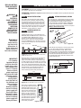
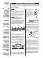
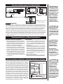
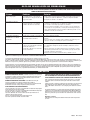
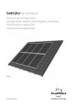
The EBHA
OWNER’S GUIDE
Models:
EBHA500
EBHA750
EBHA1000
EBHA1380
EBHA1500
EBHA500-8
EBHA750-8
EBHA1000-8
EBHA1380-8
EBHA1500-8
91/2"
24,13
Features & Benefits
31/4"
8,26
• Whisper quiet operation and low surface
temperatures
1/ 4"
• Filled with 80% water 20%38,26
Ethylene Glycol
• Self-contained hermetically sealed element design
requires no plumbing, piping, or other water supply
• Higher fluid capacity offers better heat retention,
which creates less cycling and keeps more consistent
room temperatures
• Designed to reduce the effects of indoor allergens
Tools Required:
Phillips Screwdriver
Straight Screwdriver
Wire Strippers
Drill or Hammer
Level
Punch or Chisel
Drill Bits
Utility Knife
4 Wood Screws
3 Wire Nuts
1 Strain Relief Connector
• 5-year element warranty
IMPORTANT INFORMATION
WARNING!
When working with electricity, turn the electrical power off at the electrical panel board
and lock or tag the circuit breaker door.
Failure to do so could result in serious electrical shock, burns, or possible death.
1. Read all information labels. Verify that the
electrical supply wires are the same voltage
as the heater.
6.
WARNING
Overheating or fire may occur. DO NOT place the heater behind doors.
7.
WARNING
Fire or explosion may occur. DO NOT place heater in any
area where combustible vapors, gases, liquids, or excessive
lint or dust are present.
8.
WARNING
Risk of Electrical Shock. Turn off all power at the electrical
panel board supplying power to the heater before doing
any electrical wiring.
9.
WARNING
Risk of Fire. Heater must be kept clear of all obstructions:
maintain a 12" minimum clearance in front and above the
heater with a 6" minimum on each side. Heaters must be kept
clean of lint, dirt and debris. (See Maintenance
Instructions)
2. All electrical work and materials must comply with the
National Electric Code (NEC), the Occupational Safety and
Health Act (OSHA), and all state and local codes.
3. The heater must be grounded to the grounding pigtail
(copper wire) provided.
4. If you need to install a new circuit or need additional wiring
information, consult a qualified electrician.
5. Protect electrical supply from kinks, sharp objects, oil,
grease, hot surfaces or chemicals.
WARNING! Element filled with heat transfer fluid con10.
taining 20% Ethylene Glycol and 80% water. In the unlikely
event of leakage, if consumed, call your local poison
control center or seek medical attention immediately.
SAVE THESE INSTRUCTIONS
TEL: 360-693-2505 Fax: 360-694-8668 P.O. Box 1675 Vancouver, WA 98668-1675
READ ALL INSTRUCTIONS AND SAFETY
INFORMATION.
Installation Instructions
PLACEMENT: For best results, install the Softheat baseboard heater under a window, along an outside wall,
or as close as possible to an outside door.
WARNING!
Risk of Fire.
Heater must be
kept clear of all
obstructions: 12
inches in front and
above; 6 inches on
both sides minimum.
STEP 1 AREA OF INSTALLATION
STEP 3 WIRING PROVISIONS / WIRING
The seam at the junction of the wall and floor
behind the heater should be caulked to prevent
dust from being drawn into the room. The heater
should be set flush against surface of the wall.
When installing a baseboard heater, remove any
obstructions between the back of the unit and the
surface of the wall. Keep at least 12" minimum
from objects hanging above (i.e., drapes).
This heating unit is designed for permanent installation. All wiring should be routed in compliance with
the National Electrical Code and all local codes,
where applicable. A maximum of No. 10 AWG wire
may be used with this heater. All wiring should be
planned and run before heating units are set in place.
Wiring is done on left side only.
STEP 2 MOUNTING HEATER TO
BRACKETS
ll
Wa
Two mounting brackets are furnished with each
EBHA 500, 750, and 1000 watt heater; and three for
each EBHA 1380 or 1500 watt heater. These
brackets are to be positioned at wall studs 18"
(45.7 cm) or less from each end on all models
except the EHBA 500, which should have brackets
located also at wall studs as near each end of the
heater as possible.
ut
ck O
Knoations
Loc
IN.
IN.
1 1 / 82 mm)
3
(
(95
Figure 4.
Wall Studs
Baseboard Heater
Floor
Picture not to scale
Figure 1. Front view showing location of wall studs,
EBHA unit and brackets
IMPORTANT!
It is extremely
important that you
verify the electrical
supply wires are the
same voltage as the
heater (i.e. 120 volt
heater to 120 volt
power supply and
240 volt heater to 240
volt power supply).
If replacing an
existing heater,
check the labels of
the old heater and
replace using the
same voltage.
Hooking a 240 volt
heater to a 120 volt
power supply will
drastically reduce
the heater's output.
Hooking a 120 volt
heater to a 240 volt
power supply will
destroy the heater.
3
3 / 4)
mm
.24
IN.
1
2 / 4m)
m
(57
(51 2 IN
mm .
)
WARNING!
RISK OF
ELECTRICAL
SHOCK. TURN OFF
ALL POWER AT
THE ELECTRICAL
PANEL BOARD
SUPPLYING
POWER TO THE
HEATER BEFORE
DOING ANY ELECTRICAL WIRING.
THERMOSTAT: A thermostat is required. A Cadet wall thermostat or an EBKA 1-24 end cap DPST thermostat kit
is recommended.
Place brackets at studs nearest location desired,
with bottom edges on floor against wall (See
Figure 1). Raise bracket 3/4" (19 mm) above floor
for wall-to-wall carpets to provide free circulation
of air from floor into heater. Fasten bracket to stud
with screws through elongated hole. Place spirit
level across top of brackets and level by loosening
elongated hole screw and tightening when all
brackets are absolutely level (See Figure 2).
Finish fastening brackets firmly to wall studs.
When wiring unit through rear entrance port, knock
out rear port and place heater on wall brackets.
Mark knockout location on wall. When running
conduit or cable to unit through flooring and entrance
port in bottom of junction box, measure 1-1/2" (38mm)
from wall and 2" (51mm) from left end of unit. Cut a
7/8" (22mm) hole in floor centered on the measured
location (See Figure 4).
.
ELEMENT
SUPPLY WIRES
Limit switch
T
Ground
Screw
Level
Figure 5. Wiring Diagram
Straight Edge
Brackets
Floor
Figure 2. Checking with level on top of brackets
Place heater so flange on back
near top slips down on brackets.
Slip lower edge of heater into
base of brackets (See Figure 3).
Check heater again with spirit
level to be sure it is level (See
Figure 2). If not, it may be necessary to remove and reset
brackets. Once heater is level,
use a blunt punch or chisel to Bottom
bend bracket base edge over Flange
lower lip of heater to hold
heater firmly in position.
Figure 3. Bracket
Unit
Back
Flange
Installation Instructions
Refer to wiring diagram (See Figure 5) for proper wiring of heating unit to thermostat. Illustrated in Figures 6,
7, and 8 are wiring diagrams typical of a single unit controlled by a single pole thermostat, a single unit controlled by a double pole thermostat, and two units controlled by a double pole thermostat.
Line
Line
Line
Thermal
Load
Switch
On/Off
Switch
Limit switch
Limit switch
On/Off
Switch
Heater
Figure 6. Single pole thermostat
Thermal
Load
Switch
Limit switch
Limit switch
Heater
Figure 7. Double pole thermostat
Heater #1
Heater #2
Figure 8. Double pole thermostat
with multiple units
STEP 4 THERMOSTAT
For best results, use a Cadet wall thermostat or an EBKA 1-24 end cap DPST thermostat kit. It is recommended that a thermostat be provided for each room. In extremely large rooms, a Cadet low-voltage thermostat
with double relays will give the most comfortable results. The location of the thermostat should be selected
carefully. Thermostats should not be located near drafts from an open doorway or within 18" (45.7cm) of an
outside wall, or in direct sunlight or unusual heat sources. A television set or appliance that builds up heat
near a thermostat will prevent the thermostat from functioning properly. A wiring diagram illustrating typical
wiring of the thermostat is included in literature provided with the thermostat, and on a simple diagram provided on the thermostat.
Operation & Maintenance
How To Operate Your Heater
WARNING!
Element filled with
heat transfer fluid
containing 20%
Ethylene Glycol. In
the unlikely event of
leakage, if consumed, call your
local poison control
center or seek
medical attention
immediately.
Maintenance
1. Switch the power on at the electrical panel
Softheat hydronic baseboards are virtually mainboard. PLEASE NOTE: Upon initial start-up, the
tenance-free. However, a certain amount of lint
heater may emit a burning odor. This is not danand dust will accumulate inside the unit and
gerous and is due to a protective lubricant used
should be periodically cleaned.
during the manufacturing process.
1. Turn the electrical power off at the electrical
2. Turn the thermostat fully clockwise.
panel board (circuit breaker or fuse box). Lock or
3. When the room reaches your comfort level, turn
tag the panel board door to prevent someone
the thermostat knob counterclockwise until a
from accidentally turning the power on while you
clicking sound is heard (if using a digital thermoare working on the heater. Failure to do so could
stat, set at desired room temperature). The
result in serious electrical shock, burns, or possibaseboard will automatically cycle around this
ble death.
preset temperature.
2. Remove front panel.
3. Vacuum inside the unit, being careful not to
damage the aluminum fins on the heater tube.
How Softheat Hydronic Baseboards Work
Inside a Softheat baseboard a hermetically sealed water and
anti-freeze solution is heated by an electric heating element. As
the solution is heated, warmth is generated and transmitted
through dozens of aluminum fins along the heater tube (it
could initially take 30 to 60 minutes to warm a room, depending
on the room size). As the warmth spreads outward from the
heater, cooler air from the floor and wall naturally flow toward
the base of the heater. "Convection air heating" (See Figure 9),
means no noisy fans are needed and the room is warmed with
even, comfortable heat. There will be no cold and hot spots in
the room as found with other types of heaters. Softheat won't
blow or burn dust particles, making it allergist recommended for
patients with respiratory ailments or allergies.
Cold Air
Warm Air
Room Air
Figure 9.
WARNING!
Risk of Electrical
Shock. Connect
grounding lead to
grounding wire provided. Keep all
foreign objects out
of heater.
WARNING!
Risk of Fire. Heaters
must be kept clean
of lint, dirt and
debris.
Failure to follow
warnings may
cause heater to
eject sparks, ignite
materials, or cause
electrical shock.
WARNING!
Risk of Electrical
Shock. When
working with electricity, turn the electrical power off at
the electrical panel
board and lock or
tag the circuit
breaker door.
Failure to do so
could result in
serious electrical
shock, burns, or possible death!
Troubleshooting Chart
CONSULT LOCAL ELECTRICAL CODES TO DETERMINE WHAT WORK MUST BE PERFORMED BY QUALIFIED ELECTRICAL SERVICE PERSONNEL
Symptom
Gurgling noise
Problem
Solution
1. Unit may not be level
1. Check to be sure unit is level. If gurgling doesn't stop within 30 minutes, unit
needs to be replaced.
2. Replace element or heater.
2. Unit may have developed a leak
Heater not working
1. Heater does not have proper voltage
to function correctly
2. Unit wired incorrectly
1. Circuit breaker could be positioned incorrectly. Relocate breaker. Check
voltage at the heater between supply wires and make sure it matches
required heater voltage.
2. Be sure wires are connected properly and securely with appropriate wire
nuts; by verifying with Owner's Guide. If the unit is still not operating, further
testing should be done with ohmmeter. Consult an electrician.
Liquid found in or around unit
1. Heat transfer fluid may be escaping
from element
1. Immediately discontinue use.*
2. Unit needs to be replaced.
Room does not heat quickly
1. Unit is slow to heat
2. Unit wired incorrectly
1. No solution necessary - typical initial warm-up takes 30-60 minutes.
2. Check voltage at the heater between supply wires and make sure it matches
required heater voltage.
Heater will not shut off
1. Heat loss from room is greater than
heater capacity
2. Defective thermostat
3. Thermostat wired incorrectly to
heater
1. Close doors and windows. Provide additional insulation, install a higher-wattage
heater or multiple heaters if necessary.
2. Adjust thermostat to its lowest setting. If heater continues to run (allow two minutes
for the thermostat to respond), replace thermostat..
3. Refer to thermostat documentation and correct wiring.
* What to do if the solution in your Softheat Baseboard should leak out:
The solution in your Softheat Baseboard is 80% water and 20% Ethylene Glycol (Material Safety Data Sheet available upon request). While this solution is moderately toxic if
ingested, there is no immediate health concern with air quality following a spill. Take adequate precautions to keep people and animals away from leakage. Non-porous rubber
gloves and eye protection should be worn during the clean-up.
Soak up spill with an absorbent material such as paper towels. Once excess liquid or residue has been absorbed, a non-oxidizing cleanser such as an orange citrus cleaner can
be used to remove any remaining dried residue (first test a hidden section of flooring for colorfastness). Scrub spill area, then use absorbent material to remove any remaining
cleanser. Several applications of the cleanser may be required, depending on size and amount of spill.
Warranty
LIMITED ONE-YEAR WARRANTY: Cadet Manufacturing Co. will repair
or replace any Cadet product, including thermostats, found to be
defective or malfunctioning from first date of purchase through the first
year.
CADET SHALL NOT BE LIABLE FOR DAMAGES SUCH AS PROPERTY
DAMAGE AND/OR INCIDENTAL EXPENSES RESULTING FROM
BREACH OF THESE WRITTEN WARRANTIES OR ANY IMPLIED WARRANTY.
LIMITED FIVE-YEAR WARRANTY: Cadet Manufacturing Co. will repair
or replace any Cadet/Softheat baseboard (E) element found to be
defective or malfunctioning from first date of purchase through the fifth
year.
These warranties give you specific legal rights, and you may also
have other rights which vary from state to state. Cadet neither
assumes, nor authorizes anyone to assume for it, any other obligation
or liability in connection with these electric heaters or any part of
such heaters.
These warranties do not apply:
1. To conditions resulting from improper installation or incorrect
supply voltage;
2. To conditions resulting from improper maintenance, misuse, abuse,
accident, or alteration;
3. To service calls, or any warranty labor not performed at the
Cadet Manufacturing facility;
4. If the date of manufacture cannot be determined;
5. To freight damaged products.
If the product should become defective during the warranty period,
contact Cadet Manufacturing Co. at 360-693-2505 for instructions on
how to have the repair or replacement processed. Products returned
without authorization will be refused.
Parts and Service
Contact Cadet for information on Parts or Service.
EL EBHA
GUÍA PARA EL PROPIETARIO
Modelos:
EBHA500
EBHA750
EBHA1000
EBHA1380
EBHA1500
EBHA500-8
EBHA750-8
EBHA1000-8
EBHA1380-8
EBHA1500-8
91/2"
24,13
Características y Beneficios
31/4"
8,26
• Funcionamiento silencioso y temperaturas de superficie bajas
• Rellenado con 80% de agua, 20% de glicol etilénico
31/4"
8,26
• Sistema autónomo herméticamente
sellado que no
requiere plomería, tubería u otro suministro de agua.
• Capacidad superior de líquido que ofrece mejor
retención del calor, lo que crea menos fun cionamiento
cíclico y mantiene más constantes las temperaturas del
ambiente.
• Diseñado para reducir los efectos de los alergenos del
interior
• Garantía de 5 años para el elemento.
Herramientas Requeridas:
Destornillador Phillips
Destornillador recto
Desforrador de cable
Barrena o martillo
Brocas para barrenar
Cuchillo multi-uso
4 tornillos de madera
3 tuercas de alambre
1 conector de alivio de esfuerzo
INFORMACIÓN IMPORTANTE
¡ADVERTENCIA!
Cuando esté trabajando con electricidad,
desconecte la corriente eléctrica en el tablero
del panel eléctrico y trabe o coloque un cartel
en la puerta del interruptor de circuitos. No
hacerlo podría resultar en la electrocución,
quemaduras graves o hasta la posibilidad de
muerte.
1. Lea todas las etiquetas que contengan información. Verifique que todos los cables de suministro eléctrico sean del mismo voltaje que el calentador.
2. Todo trabajo eléctrico así como los materiales deben cumplir
con el Código Eléctrico Nacional (“NEC”, por sus siglas en
inglés), con la Ley de Seguridad y Salud Ocupacional
(“OSHA”, por sus siglas en inglés) y con todos los códigos
estatales y locales.
3. El calentador debe estar conectado con el cable espiralado de
conexión a tierra (el cable de cobre) provisto.
4. Si usted necesita instalar un circuito nuevo o si necesita información adicional acerca del cableado, consulte con un electricista calificado.
5. Proteja el suministro eléctrico de enredos, objetos afilados,
aceite, grasa, superficies calientes o substancias químicas.
6.
ADVERTENCIA
Puede ocurrir un recalentamiento o incendio. NO colocar el
calentador detrás de puertas.
7.
ADVERTENCIA
Pueden ocurrir explosiones o incendios. NO colocar el calentador en ningún área donde exista la presencia de vapores,
gases, líquidos combustibles o exceso de pelusa o polvillo.
8.
ADVERTENCIA
Riesgo de electrocución. Desconectar la energía eléctrica en
el tablero de panel que suministra la corriente al calentador
antes de llevar a cabo el cableado para la electricidad
9.
ADVERTENCIA
Riesgo de Incendio. El calentador debe mantenerse libre de
toda obstrucción, mantener un espacio mínimo de 12 pulgadas desde la parte de adelante y por encima del calentador
y un mínimo de 6 pulgadas de cada costado. Los calentadores
deben mantenerse libres de pelusa, suciedad y residuos (Ver
las Instrucciones para el Mantenimiento).
10.
¡ADVERTENCIA! Elemento rellenado con líquido de
transferencia de calor que contiene un 20% de glicol etilénico
y 80% de agua. En el improbable caso de que existieran fugas,
de ingerirse, deberá llamar al centro de control de envenenamientos o solicitar atención médica de inmediato.
CONSERVE ESTAS INSTRUCCIONES
TEL: 360-693-2505 Fax: 360-694-8668 P.O. Box 1675 Vancouver, WA 98668-1675
LEA TODAS LAS
INSTRUCCIONES E
INFORMACIÓN
ACERCA DE LA
SEGURIDAD.
Instrucciones para la Instalación
UBICACIÓN: Para obtener mejores resultados, instalar el calentador de plinto radiante Softheat debajo de
una ventana junto a una pared exterior o tan cerca como resulte posible de una puerta que da al exterior.
TERMOSTATO: Se requiere un termostato. Se recomienda un termostato de pared Cadet o un juego de termostato
¡ADVERTENCIA!
Riesgo de incendio.
El calentador debe
mantenerse libre de
toda obstrucción: a 12
pulgadas en la parte
de adelante y por
arriba; a 6 pulgadas
como mínimo de cada
costado.
DPST con casquete EBKA 1-24.
Paso 1 AREA DE INSTALACIÓN
La junta en la unión de la pared y el piso detrás de
los calentadores deberá calafatearse para evitar
que se atraiga el polvillo hacia la habitación. Los
calentadores deberán colocarse al ras contra la
superficie de la pared. Al instalar calentadores de
plinto radiante, quitar toda obstrucción entre la
parte posterior de la unidad y la superficie de la
pared. Mantener a por lo menos 12” como mínimo
de objetos que cuelguen desde arriba (por
ejemplo cortinados).
Paso 2 MONTAJE DEL CALENTADOR
A LAS ABRAZADERAS
Se proporcionan dos abrazaderas con cada
calentador EBHA de 500, 750 o 1000 vatios y tres
con cada calentador EBHA de 1380 y 1500 vatios.
Estas abrazaderas deben ubicarse en soportes de
la pared a 18 pulgadas (45.7 cm) o menos de cada
extremo en todos los modelos, con excepción del
EBHA 500 que debe tener las abrazaderas ubicadas también en los soportes de la pared tan
cerca de cada extremo del calentador como
resulte posible.
Soportes Wall
de la pared
Studs
Calentador
de plinto
radiante
Baseboard
Heater
¡IMPORTANTE!
Es de extrema importancia que usted verifique los cables de
suministro eléctrico
para asegurarse de
que sean del mismo
voltaje que los del
calentador (es decir,
un calentador de 120
voltios con un suministro de energía de 120
voltios y un calentador
de 240 voltios con un
suministro de energía
de 240 voltios).
Cuando esté reemplazando un calentador existente,
verifique las etiquetas
del calentador viejo y
reemplácelo utilizando el mismo voltaje. Si
conecta un calentador
de 240 voltios con un
suministro de 120
voltios reducirá drásticamente el
rendimiento del calentador. Si conecta un
calentador de 120
voltios con un suministro de energía de 240
voltios destruirá el
calentador.
Floor
Piso
Dibujo no a escala
Figura 1. Vista de adelante que indica la ubicación
de los soportes de la pared, de la unidad EBHA y de las
abrazaderas.
Colocar las abrazaderas en los soportes más cercanos al lugar deseado, con los bordes inferiores
sobre el piso y contra la pared (Ver la Figura 1).
Elevar la abrazadera 3/4 pulgada (19 mm) por
encima del piso cuando haya alfombrados de
pared a pared para poder proporcionar la circulación libre del aire desde el piso hacia el calentador. Ajustar la abrazadera al soporte con los
tornillos a través del orificio alargado. Colocar el
nivel de burbuja de aire a través de la parte superior de las abrazaderas y nivelar aflojando el
tornillo de orificio alargado y ajustando cuando
todas las abrazaderas estén absolutamente niveladas (Ver la Figura 2). Terminar de ajustar las
abrazaderas con firmeza en los soportes de la
Nivel
Level
Borde recto
Straight
Edge
esté a nivel (Ver la Figura 2).
De no estarlo, es posible que
sea necesario quitar y volver
a ubicar las abrazaderas.
Una vez que estén a nivel,
utilice un agujereador o
cincel para doblar el borde
de la base de la abrazadera
por encima del labio inferior
del calentador y sostener el
calentador firmemente en
posición.
Unit
Back
Flange
Bottom
Flange
Figura 3. Abrazadera
Paso 3 DISOSICIONES PARA EL CABLEADO / CABLEADO
Esta unidad de calefacción ha sido diseñada para
ser instalada de forma permanente. Todo cableado
deberá realizarse en cumplimiento con los Códigos
Eléctricos Nacionales y con todos los códigos
locales donde resulten pertinentes. Se puede utilizar
un cable Nº 10 AWG como máximo con este calentador. Hay un diagrama completo de cableado ubicado
en la parte interior de la tapa de la caja de circuito.
Todo cableado deberá planearse y realizarse antes
de colocar las unidades de calefacción en su lugar.
El cableado se realiza solamente del lado izquierdo.
Pared
ll
Wa
3
3 / 4)
m
4
2 m
.
(95
IN.
1
2 / 4m)
m
(57
as
de l bles
s
e
nta
iton
ckaOcu smo
UKnboiactziaonssde
ocie
Lp
IN.
IN.
1 1 / 82 mm)
(3
(51 2 IN
mm .
)
¡ADVERTENCIA!
RIESGO DE
ELECTROCUCIÓN.
DESCONECTAR LA
ENERGÍA
ELÉCTRICA EN EL
TABLERO DE PANEL
QUE SUMINISTRA
LA CORRIENTE AL
CALENTADOR
ANTES DE LLEVAR A
CABO EL CABLEADO
PARA LA ELECTRICIDAD.
Figura 4.
Al cablear la unidad a través de la entrada trasera,
desmonte la entrada trasera y coloque el calentador
sobre las abrazaderas de pared. Marque la ubicación de la pieza desmontable en la pared. Al
colocar los conductos o cables que van a la unidad
a través del piso y de la entrada de la parte inferior
de la caja de conexión, mida 1 1/2” (38 mm) desde la
pared y 2 pulgadas (51 mm) desde el extremo
izquierdo de la unidad. Corte un orificio centrado de
7/8” (22 mm) en el piso sobre el lugar donde tomó la
medida (Ver la Figura 4).
Brackets
Abrazaderas
Floor
Piso
Figura 2. Verificar con el nivel colocado en la parte
superior de las abrazaderas.
Colocar el calentador de modo tal que la aleta de
la parte posterior cerca de la parte superior calce
en las abrazaderas. Haga calzar el borde inferior
del calentador en la base de las abrazaderas (Ver
la Figura 3). Verifique el calentador nuevamente
con el nivel de burbuja para asegurarse de que
Refiérase al diagrama de cableado (Ver la Figura 5)
para determinar la forma apropiada de realizar el
cableado de la unidad de calefacción que va al termostato. Ilustrado en las Figuras 6, 7 y 8 se encuentran los diagramas de cableado típicos de una
unidad simple controlada por un termostato de un
solo polo, una unidad simple controlada por un termostato de doble polo y dos unidades controladas
por un termostato de doble polo.
Instrucciones para la Instalación
ELEMENT
Line
Línea
Line
Línea
Thermal
Interruptor
Load
de carga
Switch
Field Wiring
SUPPLY WIRES
térmica
Rojo
T
Tornillo
Ground
a tierra
Screw
Limit switch
Calentador
Heater
On/Off
Figura 6. Termostato de
un solo polo
Line
Línea
Figura 5. Diagrama de Cableado
Interruptor
On/Off
Encender/
Switch
Apagar
Limit switch
Paso 4 TERMOSTATO
Calentador
1
Heater #1
Interruptor
Switch
Limit switch
Calentador
Encender/Apagar
Heater
Figura 7. Heater
Termostato
Element
de doble polo
Interruptor
Thermal
deLoad
carga
Switch
térmica
Limit switch
Calentador
2
Heater #2
Red
Figura 8. Termostato
der Tu
doble
Red
be
Heate
polo con unidades múltiples.
Limit
Para obtener mejores resultados, utilice un termostato de pared Cadet o un juego de termostato
DPST con
capacete EBKA 1-24. Se recomienda que se proporcione un termostato para cada habitación. En las habitaciones extremadamente grandes, se obtienen mejores resultados con un termostato Cadet de bajo voltaje
con dos relés. La ubicación del termostato deberá seleccionarse con mucho cuidado. Los termostatos no
deberán estar ubicados cerca de corrientes de aire provenientes de una puerta abierta o dentro de un
espacio de 18 pulgadas (45.7 cm) de una pared exterior o en contacto directo con la luz del sol o con fuentes
de calor inusuales. Un aparato de televisión o electrodoméstico que acumule calor cerca de un termostato
evitará que el termostato funcione apropiadamente. La documentación que viene con el termostato incluye
un diagrama de cableado que ilustra el cableado típico del termostato; y dicho aparato incluye también
un diagrama sencillo.
¡ADVERTENCIA!
Elemento rellenado
con líquido de transferencia de calor que
contiene 20% de
glicol etilénico. En el
improbable caso de
que existiera una
fuga, si se ingiriera,
llame al centro de
control de envenenamientos local o
solicite atención
médica de inmediato.
¡ADVERTENCIA!
Riesgo de electrocución. Conectar el
conector a tierra con
el cable a tierra provisto. Mantener todos
los objetos extraños
alejados del calentador.
Funcionamiento y Mantenimiento
Cómo Hacer Funcionar su Calentador
Mantenimiento
1. Conectar la energía en el tablero del panel eléctrico.
Los plintos radiantes hidrónicos Softheat virtualmente no necesitan mantenimiento. Sin embargo,
POR FAVOR ADVIERTA: Al encender inicialmente,
una cierta cantidad de pelusa y polvillo se acumuel calentador emitirá un olor a quemado. Esto no es
larán en el interior de la unidad y deberá limpiarse
peligroso y es debido al lubricante protector utiperiódicamente.
lizado durante el proceso de fabricación.
2. Haga girar el termostato completamente en el 1. Desconecte la energía eléctrica en el tablero del
panel eléctrico (interruptor de circuito o caja de
mismo sentido que giran las manecillas del reloj.
fusibles). Trabe o coloque un cartel en la puerta del
3. Cuando la habitación alcance el nivel de comoditablero del panel para evitar que alguien conecte la
dad que usted desea, haga girar la perilla del terenergía accidentalmente mientras usted está tramostato en sentido contrario al que giran las
bajando en el calentador. No hacerlo podría resulmanecillas del reloj hasta escuchar un chasquido
tar en la electrocución, quemaduras graves o
(si está utilizando un termostato digital, graduar a
hasta en la muerte.
la temperatura ambiente deseada). El tablero hará 2. Quitar el panel de adelante.
un ciclo automático en torno a esta temperatura 3. Aspire el interior de la unidad, con cuidado de no
preestablecida.
dañar la aletas de aluminio en el tubo del calentador.
¡ADVERTENCIA!
Riesgo de incendio.
Los calentadores
deben mantenerse
libres de pelusa,
polvillo y residuos.
No respetar las
advertencias podría
hacer que el calentador despidiera
chispas, encendiera
materiales o causara
la electrocución.
Como funcionan los plintos radiantes hidrónicos Softheat
Dentro de un plinto radiante Softheat una solución herméticamente sellada de agua y anticongelante se calienta a
través de un elemento de calefacción eléctrico. A medida
que la solución se calienta, se genera un calor que se transmite a través de docenas de aletas de aluminio a lo largo del
tubo del calentador (inicialmente podría tardar de 30 a 60
minutos para calentar una habitación de acuerdo al tamaño de
la misma). A medida que el calor se distribuye hacia afuera
desde el calentador, aire más frío del piso y de la pared fluyen
naturalmente hacia la base del calentador. “Calefacción con
aire de convección” (Ver la Figura 9) significa la ausencia de
ventiladores ruidosos ya que estos no resultan necesarios y
la habitación se calienta con calor parejo y cómodo. No
habrá lugares fríos y calientes en la habitación como es el caso
con otros tipos de calentadores. Softheat no soplará ni
quemará partículas, convirtiéndolo en un aparato recomendado
para pacientes con trastornos respiratorios o alergias por
parte de los médicos especialistas en alergia.
Co
ld Air
Aire
Frío
Air
Aire
Caliente
Warm
AireRoom
de la habitación
Air
Figura 9.
¡ADVERTENCIA!
Riesgo de electrocución. Cuando trabaje
con electricidad,
apague la energía
eléctrica en el
tablero del panel
eléctrico y trabe o
coloque un cartel en
la puerta del interruptor de circuitos. ¡No
hacerlo podría resultar en electrocución,
quemaduras graves o
hasta en la posibilidad de muerte!
GUÍA DE RESOLUCIÓN DE PROBLEMAS
CONSULTAR CON LOS CÓDIGOS DE ELECTRICIDAD LOCALES PARA DETERMINAR QUE PARTE DEL TRABAJO DEBE SER REALIZADA POR PERSONAL DE SERVICIO ELÉCTRICO CALIFICADO.
Síntoma
Problema
Solución
Ruido como gorgoteo
1. La unidad puede no estar nivelada
2. Es posible que se haya producido una
fuga en la unidad.
1. Verificar para asegurarse de que la unidad esté nivelada. Si el gorgoteo no
se detiene en un plazo de 30 minutos, se deberá reemplazar la unidad.
2. Reemplace el elemento o el calentador.
El calentador no funciona
1. El calentador no tiene el voltaje apropiado para funcionar correctamente.
2. Unidad cableada incorrectamente.
1. El cortacircuito podría estar mal dispuesto. Colóquelo en otro lugar. Revise
el voltaje en el calentador entre los alambres de suministro y cerciórese de
que coincida con el voltaje que requiere el calentador.
2. Cerciórese de que los alambres estén conectados correcta y firmemente
con las tuercas correspondientes; consulte para ello la Guía para el propietario. Si la unidad aún no funciona, se deben realizar más pruebas con un
ohmímetro. Consulte a un electricista.
Líquido encontrado en el inter
or o alrededor de la unidad.
1. El líquido de transferencia de calor
1. Deje de utilizar inmediatamente.*
puede estar escapándose del elemento. 2. Se debe reemplazar la unidad.
1. No necesita solución – el entibiamiento inicial típico tarda de 30 a 60
1. La unidad tarda en calentarse.
minutos.
2. Revise el voltaje en el calentador entre los alambres de suministro y verifique que coincida con el voltaje que requiere el calentador.
La habitación no se calienta
rápidamente
El calentador no se apaga
1. La pérdida de calor en la habitación es
superior a la capacidad del calentador.
2. Termostato defectuoso.
3. Termostato cableado incorrectamente
hacia el calentador.
1. Cerrar las puertas y ventanas. Proporcionar aislamiento adicional, instalar
un calentador de vatiaje más elevado o múltiples calentadores si fuera
necesario.
2. Ajustar el termostato a la graduación más baja. Si el calentador continúa
funcionando (permita el transcurso de dos minutos para que el termostato
responda), reemplace el termostato.
3. Refiérase a la documentación del termostato y cableado correcto.
*¿Qué hacer si hubiera fugas de solución en su calefactor Softheat Baseboard:
La solución del Softheat Baseboard está compuesta en un 80% por agua y en un 20%
por glicol de etileno (puede solicitar la Hoja de Datos de Seguridad de Materiales si lo desea). Si bien esta solución es moderadamente tóxica si se
ingiere, no debiera haber inquietudes sanitarias inmediatas respecto de la calidad del aire tras un derrame. Adopte las precauciones pertinentes para
mantener a las personas y animales lejos de la fuga. Utilice guantes no porosos de caucho y protectores oculares durante la limpieza.
Seque el derrame con un material absorbente como toallas de papel. Una vez que ha absorbido el líquido o los residuos, puede usar un limpiador no
oxidante como uno cítrico de naranja para eliminar los residuos secos restantes (primero haga una prueba en una zona oculta del piso para verificar
que no se destiña). Friegue la zona del derrame y luego use un material absorbente para quitar el limpiador que pudiera quedar. Puede que se deba
aplicar el limpiador varias veces, dependiendo del tamaño y la cantidad del derrame.
Garantía
GARANTIA LIMITADA DE UN AÑO: Cadet Manufacturing Co. reparará o
reemplazará cualquier producto Cadet, incluyendo termostatos que se
determine es defectuoso o está funcionando mal desde la fecha de
compra original hasta el primer año.
GARANTIA LIMITADA DE CINCO AÑOS: Cadet Manufacturing Co.
reparará o reemplazará cualquier elemento (E) de tablero
Cadet/Softheat ® que se determine es defectuoso o está funcionando
mal desde la fecha de compra original hasta el quinto año.
ESTAS GARANTíAS NO SON PERTINENTES:
1) Para condiciones que sean el resultado de la instalación inapropiada
o del suministro incorrecto de voltaje;
2) Para condiciones que sean el resultado del mantenimiento inapropiado, mal uso, abuso, accidente o alteración
3) Para las llamadas de servicio o mano de obra que involucren el
cambio de pieza(s) defectuosa(s)
4) Si no se puede determinar la fecha de fabricación
5) Para los productos dañados durante el flete.
CADET NO SERÁ RESPONSABLE DE LOS DAÑOS A LA PROPIEDAD Y/O
GASTOS INCIDENTALES QUE RESULTEN DEL INCUMPLIMIENTO DE
ESTAS GARANTÍAS ESCRITAS O DE CUALQUIER GARANTIA IMPLICITA.
Estas garantías le otorgan derechos legales específicos y es posible
que usted cuente con otros derechos que varían de acuerdo a cada
estado.
Cadet no asume ni autoriza a nadie para que asuma de su parte ninguna
otra obligación o responsabilidad contra terceros relacionada con
estos calentadores eléctricos o con cualquier parte de dichos calentadores.
Si el producto llegara a ser defectuoso durante el período de garantía,
comunicarse con Cadet Manufacturing llamando al 360-693-2505 para
obtener instrucciones acerca de como procesar la reparación o reemplazo. Los productos que se devuelvan sin autorización serán rechazados.
Repuestos y servicio
Comuníquese con Cadet para obtener información sobre repuestos o
servicio.
#706955 REV. C 07/05