1
READ ALL INSTRUCTIONS AND SAFETY
INFORMATION.
Installation Instructions
PLACEMENT: For best results, install the Softheat baseboard heater under a window, along an outside wall,
or as close as possible to an outside door.
WARNING!
Risk of Fire.
Heater must be
kept clear of all
obstructions: 12
inches in front and
above; 6 inches on
both sides minimum.
STEP 1 AREA OF INSTALLATION
STEP 3 WIRING PROVISIONS / WIRING
The seam at the junction of the wall and floor
behind the heater should be caulked to prevent
dust from being drawn into the room. The heater
should be set flush against surface of the wall.
When installing a baseboard heater, remove any
obstructions between the back of the unit and the
surface of the wall. Keep at least 12" minimum
from objects hanging above (i.e., drapes).
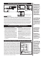
This heating unit is designed for permanent installation. All wiring should be routed in compliance with
the National Electrical Code and all local codes,
where applicable. A maximum of No. 10 AWG wire
may be used with this heater. All wiring should be
planned and run before heating units are set in place.
Wiring is done on left side only.
STEP 2 MOUNTING HEATER TO
BRACKETS
ll
Wa
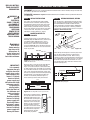
Two mounting brackets are furnished with each
EBHA 500, 750, and 1000 watt heater; and three for
each EBHA 1380 or 1500 watt heater. These
brackets are to be positioned at wall studs 18"
(45.7 cm) or less from each end on all models
except the EHBA 500, which should have brackets
located also at wall studs as near each end of the
heater as possible.
ut
ck O
Knoations
Loc
IN.
IN.
1 1 / 82 mm)
3
(
(95
Figure 4.
Wall Studs
Baseboard Heater
Floor
Picture not to scale
Figure 1. Front view showing location of wall studs,
EBHA unit and brackets
IMPORTANT!
It is extremely
important that you
verify the electrical
supply wires are the
same voltage as the
heater (i.e. 120 volt
heater to 120 volt
power supply and
240 volt heater to 240
volt power supply).
If replacing an
existing heater,
check the labels of
the old heater and
replace using the
same voltage.
Hooking a 240 volt
heater to a 120 volt
power supply will
drastically reduce
the heater's output.
Hooking a 120 volt
heater to a 240 volt
power supply will
destroy the heater.
3
3 / 4)
mm
.24
IN.
1
2 / 4m)
m
(57
(51 2 IN
mm .
)
WARNING!
RISK OF
ELECTRICAL
SHOCK. TURN OFF
ALL POWER AT
THE ELECTRICAL
PANEL BOARD
SUPPLYING
POWER TO THE
HEATER BEFORE
DOING ANY ELECTRICAL WIRING.
THERMOSTAT: A thermostat is required. A Cadet wall thermostat or an EBKA 1-24 end cap DPST thermostat kit
is recommended.
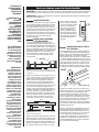
Place brackets at studs nearest location desired,
with bottom edges on floor against wall (See
Figure 1). Raise bracket 3/4" (19 mm) above floor
for wall-to-wall carpets to provide free circulation
of air from floor into heater. Fasten bracket to stud
with screws through elongated hole. Place spirit
level across top of brackets and level by loosening
elongated hole screw and tightening when all
brackets are absolutely level (See Figure 2).
Finish fastening brackets firmly to wall studs.
When wiring unit through rear entrance port, knock
out rear port and place heater on wall brackets.
Mark knockout location on wall. When running
conduit or cable to unit through flooring and entrance
port in bottom of junction box, measure 1-1/2" (38mm)
from wall and 2" (51mm) from left end of unit. Cut a
7/8" (22mm) hole in floor centered on the measured
location (See Figure 4).
.
ELEMENT
SUPPLY WIRES
Limit switch
T
Ground
Screw
Level
Figure 5. Wiring Diagram
Straight Edge
Brackets
Floor
Figure 2. Checking with level on top of brackets
Place heater so flange on back
near top slips down on brackets.
Slip lower edge of heater into
base of brackets (See Figure 3).
Check heater again with spirit
level to be sure it is level (See
Figure 2). If not, it may be necessary to remove and reset
brackets. Once heater is level,
use a blunt punch or chisel to Bottom
bend bracket base edge over Flange
lower lip of heater to hold
heater firmly in position.
Figure 3. Bracket
Unit
Back
Flange