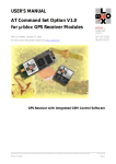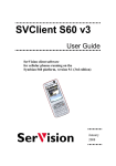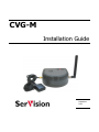
1
CVG-M Installation Guide September 2013 SerVision CVG-M Installation Guide Trademarks & Copyright Trademarks All trademarks mentioned in this manual are the sole property of their respective manufacturers. Copyright SerVision Ltd., Jerusalem, Israel www.servision.net • [email protected] © 2013 SerVision Ltd. All rights reserved. Notice Information in this document is subject to change without notice. SerVision Ltd. assumes no responsibility for any errors that may appear in this manual. Companies, names and data used in examples herein are fictitious unless otherwise noted. No part of this document may be copied or reproduced in any form, or by any means, electronic or mechanical, for any purpose, without the express written permission of SerVision Ltd. SerVision Ltd. makes no warranties with respect to this documentation and disclaims any implied warranties of merchantability or fitness for a particular purpose. 1 SerVision CVG-M Installation Guide Table of Contents Introduction 3 The CVG-M Package 4 Additional Equipment 6 Installing the CVG-M System Selecting a Location for the Unit 7 7 Preventing Overheating 8 Diagrams of Connectors 10 Supplying Power to Devices Connected to the Unit 11 Turning the Device Power On and Off with the Ignition Transforming the Supplied Voltage to 12V Configuring the Power-Supply Activator Connecting Devices to the CVG-M 11 12 13 14 Connecting Cameras 14 Connecting a PTZ Controller Connecting Sensors 14 16 Connecting a Sensor Directly to the Unit Connecting Sensors Using an ADAM Module 16 17 Connecting an Activator Connecting Sensors and Activators Using an IA Relay Board 20 21 Connecting a Microphone 22 Connecting a Speaker or Headphones 23 Connecting a CCTV Monitor 23 Connecting a Switch Connecting Multiple Monitors Connecting the CVG-M to a Network 25 25 26 LAN Connection 26 Cellular Connection 26 Connecting the Cellular Antenna Inserting the SIM Card 26 26 Connecting the GPS Antenna 28 Connecting the CVG-M to a Power Source Connecting the Wire Connector to the Unit 29 29 Connecting the Unit to an Electrical Outlet Connecting the CVG-M to a Vehicle Battery 30 31 Appendix 1: Removing the MicroSD Card Removing the MicroSD Card from the Unit 34 34 Inserting a MicroSD Card into the Unit 34 Appendix 2: Using the 12VDC Power Out Connector 36 2 SerVision CVG-M Installation Guide Introduction This guide explains how to set up the hardware components of SerVision’s CVG-M security system. The CVG-M belongs to SerVision’s line of embedded Video Gateway units. These units provide state-of-the-art security functionality, including live video streaming, video recording and playback, motion detection, sensor management, real-time event notification, and device activation. All of these features can be accessed remotely via PC, PDA, or cellular telephone. The CVG-M is optimized for deployment in vehicles and other mobile platforms or remote locations in which a LAN connection is not available. It has built-in support for cable-based and cellular networking, and contains an internal GPS receiver that makes it possible to track its location and route. It can also be integrated with some fleetmanagement systems (such as the Galooli system; see http://www.galooli.com/solutions/galooli-fleet/). Once the CVG-M has been installed as explained in this guide, it must be configured. Configuration is performed by connecting to the CVG-M unit using a PC that is on the same network as the unit (or connected to the unit directly using a LAN cross cable) and opening the unit’s configuration utility in a browser. For additional information about configuring your CVG-M, please refer to the Embedded Video Gateway System Guide. Client software is used for accessing the CVG-M unit remotely in order to view video and events and control the system in various ways. SerVision offers client software for PCs and for certain cellular telephone and PDA models. Full instructions for the use of the client applications are available in separate manuals, which can be downloaded at http://www.servision.net. Introduction 3 SerVision CVG-M Installation Guide The CVG-M Package The CVG-M package contains the following items: Item Description CVG-M unit Video Gateway Ethernet (LAN) cable Connects the unit to a PC (or a cable-based local network) RS232/485 serial adapter Connects PTZ controllers to the unit GPS antenna Enables the built-in GPS receiver to connect to satellites Modem antenna Enables the built-in cellular modem to connect to the internet via the cellular network MicroSD memory card Stores recorded video and other data Illustration Note: The unit is supplied with the memory card in its slot. The CVG-M Package 4 SerVision CVG-M Installation Guide Item Description Power-supply cable Connects the power-supply to the unit Illustration Note: For large orders, only a small number of power-supply cables are normally supplied (see note below). Power-connector cable Connects the power-supply to an electric outlet Note: For large orders, only a small number of power-connector cables are normally supplied (see note below). Power cord Connects the unit to the vehicle battery via the cigarette lighter Note: Normally supplied only with demo units (see note below). NOTE: The power-supply cable, the power-connector cable, and the power cord with cigarette-lighter connector are not required for operation of the CVG-M in a vehicle, because the unit is hard-wired to the vehicle battery when it is installed. Typically, the CVG-M unit is configured in an office setting before it is installed, and for that the power-supply and power-connector cables are used. Since only a small number of units are configured at one time, power-supply and power-connector cables are not required for every unit of a large order. After configuration, the units normally only need power-supply and power-connector cables if they malfunction and are removed from the vehicles in which they are installed in order to perform troubleshooting procedures on them in the office. The power cord, which has a cigarette-lighter connector, is not required for normal installations; it is useful primarily for testing of demo units, which are not installed in the vehicles or hardwired to the battery. In keeping with SerVision’s “green” policy of preventing unnecessary waste, only a limited number of power-supply and power-connector cables are supplied with each order. Please retain the cables you receive for use with all of the units you purchase. Similarly, power cords with cigarette-lighter connectors are only supplied with demo units. If you require more of any of these items than are normally supplied, please consult yours sales representative. The CVG-M Package 5 SerVision CVG-M Installation Guide Additional Equipment One or two video cameras should be connected to the CVG-M. You must acquire the cameras you require; they are not included in the CVG-M package. For information about camera compatibility and about connecting the cameras to the unit, see Connecting Cameras, page 14, or consult your vendor. In addition to the cameras, you may wish to connect some or all of the optional equipment listed below to the CVGM unit. For additional information about these items and the cables required to connect them, please refer to the installation instructions for each type of device. NOTE: This equipment is not included in the CVG-M package. • SIM card for the cellular network • Dry-contact sensor, toggle (on-off) switch to change the active outline (see Connecting Sensors, page 16), or push-button switch to change the display in a connected CCTV monitor (see Connecting a Switch, page 25) Note: A dry-contact sensor or switch can be connected directly to the Sensor connector on the CVG-M unit. If you use either an ADAM module or an IA relay board, as described below, you can connect an additional 16 dry-contact sensors via the unit’s RS232/485 connector. Note: If you connect a touchscreen monitor to the CVG-M, you cannot also connect an ADAM module or an IA relay board. • ADAM Data Acquisition Module and ADAM isolated RS232->RS422/RS485 converter, for connecting up to 16 dry-contact sensors (see Connecting Sensors, page 16) • Intelligent Appliance IA-3126-2 relay board, for connecting up to 16 dry-contact sensors (see Connecting Sensors and Activators Using an IA Relay Board, page 21) and 16 activators to the CVG-M unit • Dry-contact activator (an alarm or other device that is turned on or off in response to the activation of a sensor; see Connecting an Activator, page 20) Note: An activator can be connected directly to the CVG-M unit. If you use an IA relay board, as described above, you can connect an additional 16 activators via the unit’s RS232/485 connector. Note: If you connect a touchscreen monitor to the CVG-M, you cannot also connect an IA relay board. In this case, you can only connect one activator to the unit. • Microphone (see Connecting a Microphone, page 22) • Speaker or headphones (the unit already contains a built-in speaker; see Connecting a Speaker or Headphones, page 23) • CCTV monitor for closed-circuit video display (see Connecting a CCTV Monitor, page 23) • Insulated plastic container with two built-in fans in which the CVG-M unit can be placed (see Preventing Overheating, page 8) • Additional microSD cards (see Appendix 1: Removing the MicroSD Card, page 34) Additional Equipment 6 SerVision CVG-M Installation Guide Installing the CVG-M System These are the steps that you will typically follow in order to install the CVG-M system: 1. Insert the SIM card into the SIM-card slot; see Inserting the SIM Card, page 26. 2. Place the CVG-M unit in its desired location; see Selecting a Location for the Unit, page 7. Note: If you are installing the CVG-M in an insulated container (see Preventing Overheating, page 8), you must install the container in the vehicle and the CVG-M in the container. 3. Install the video cameras in their desired locations. 4. Install a CCTV monitor in its desired location (optional). 5. Install either a dry sensor, a toggle switch (for outline switching), or a push-button switch (for changing the display on a connected CCTV monitor) in its desired location (optional); see Connecting Sensors, page 16. 6. Install an alarm or other activator in its desired location (optional); see Connecting an Activator, page 20. 7. If you are using either an ADAM module to connect additional sensors to the CVG-M, install the sensors in their desired locations (optional); see Connecting Sensors, page 16. 8. If you are using an IA relay board to connect additional sensors or activators to the CVG-M, install them in their desired locations (optional); see Connecting Sensors and Activators Using an IA Relay Board, page 21. 9. Connect the cameras and other devices to the CVG-M, as required; see Connecting Devices to the CVG-M, page 14. 10. Connect the unit to a LAN using an Ethernet cable (optional); see Connecting the CVG-M to a Network, page 26. 11. Install the GPS antenna in an appropriate location in the vehicle and connect it to the unit (optional); see Connecting the GPS Antenna, page 28. 12. Connect the cameras and other devices to the vehicle battery, as required; see Supplying Power to Devices Connected to the Unit, page 11. 13. Connect the CVG-M unit to a power source; see Connecting the CVG-M to a Power Source, page 29. NOTE: If the unit is being installed in a vehicle, the devices connected to it, and the cables used to connect them, must all be securely fastened to the vehicle to ensure they do not become detached from their locations when the vehicle is in motion. NOTE: Installing the unit and its peripheral equipment in a vehicle is a complex process. It is highly recommended that it be performed by a trained specialist in vehicle installations. Selecting a Location for the Unit The CVG-M unit should be placed on a flat surface such as a shelf. (It is not designed for mounting directly on a wall.) If it is being installed in a vehicle, the unit should be installed in a cool and ventilated location, protected from direct sunlight and water (including liquids used to clean the inside of the vehicle), and as far away from humidity as possible. It should not be installed in a closed location, such as the in the trunk or dashboard, or under Installing the CVG-M System 7 SerVision CVG-M Installation Guide the paneling, of a car. Ensure the unit has at least 20 centimeters (eight inches) of space above it and on all sides for ventilation. When choosing a location for the CVG-M, bear in mind that the unit must be connected to a power source and a LAN or a PC, and that other devices (cameras, sensor, etc.) must be connected both to it and to power sources. If the unit will be installed in a vehicle, it must be connected to the vehicle battery and ignition (if required), and the cellular and GPS antennas must be located relatively high up and in exposed locations (see Connecting the Cellular Antenna, page 26; Connecting the GPS Antenna, page 28) Choose a location in which these connections are feasible. Preventing Overheating CVG-M units should be installed in the passenger compartment in a location that is cooled by the vehicle's airconditioning when the air conditioner is on. Ideally, the units should be installed in insulated plastic containers with built-in fans. Each container should have two fans, one to draw cool air into the container and the other to push hot air out of it. Containers of this type are available for purchase from vehicle-accessory suppliers. The containers should be installed in the vehicles in accessible locations, with as much ventilation as possible. The ends of cellular and GPS antennas should be placed outside the containers. If you plan to remove the micro-SD card from the unit without removing the unit from the container, make sure to allow enough space at the front of the unit to do so (see Appendix 1: Removing the MicroSD Card, page 34). NOTE: Do not install the unit in a metal container; metal interferes with wireless reception. Fan Fan Figure 1: Video Gateway installed in an insulated plastic container with two fans Installing the CVG-M System 8 SerVision CVG-M Installation Guide Figure 2: Video Gateway installed in an insulated container and attached to the back of a seat in a car In buses and trains, the CVG-M can be installed in an air-conditioning duct or in the compartment above the driver's seat. Figure 3: Video Gateway installed in the air-conditioning duct of a bus Figure 4: Video Gateway installed in the compartment above the driver's seat in a bus Installing the CVG-M System 9 SerVision CVG-M Installation Guide Diagrams of Connectors The rear and sides of the CVG-M unit contain the following connectors. SIM card MicroSD Card 12VDC Power Out SIM indicator GPS Antenna Modem Antenna Audio In (Ain1) Audio Out (Aout) Video In (Vin2) TV-Out Video In (Vin1) Ethernet Out Power RS232/485 Activator (Out1) Sensor (In1) Figure 5: CVG-M connectors Audio Out GPS antenna Audio In (Ain1) Figure 6: CVG-M connectors: left panel Installing the CVG-M System 10 SerVision CVG-M Installation Guide Connector Description Modem Antenna Connector for the supplied cellular-modem antenna (see page 26) 12VDC Power Out Supplies power to external devices such as sensors (see page 36) MicroSD Card Slot for the microSD card (see page 34) SIM Card Slot for a SIM card (see page 26) SIM indicator Cellular activity indicator – lit when the connection to the cellular network is active TV Out Connector for a CCTV monitor (see page 23) Video In (Vin1 and Vin2) Connectors for video cameras (see page 14) GPS Antenna Connector for the supplied GPS antenna (see page 28) Audio In (Ain1) Connector for a microphone (see page 22) Audio Out (Aout) Connector for an external speaker or headphones (see page 23) Ethernet Out 10/100 Base-T LAN connector for connecting the unit to an external network (LAN or WAN; see page 26) Sensor (In1) Sensor connector (see page 16) Activator (Out1) Activator connector (see page 20) Power Connector for the power supply and, if required, for the ignition connection (see page 29) RS232/485 Serial (COM) port for PTZ controllers (see page 14), a touch-screen controller (see page 23), a device to receive GPS location data (for additional information, consult your vendor), or technicians' use Supplying Power to Devices Connected to the Unit Cameras and most other peripherals connected to the CVG-M unit usually require independent power supplies. These devices should be connected directly to the vehicle battery (or some other power source). NOTE: In some cases, it may be possible to provide power to certain devices through the 12VDC Power Out connector on the rear panel of the CVG-M. This option is not appropriate for supplying power to cameras. For additional information, see Using the 12VDC Power Out Connector, page 36. Turning the Device Power On and Off with the Ignition When the CVG-M is installed in a vehicle, it is normally configured to shut down whenever the vehicle ignition is turned off. All devices that draw their power through the 12VDC Power Out connector on the CVG-M are also turned off when the CVG-M shuts down, because they do not receive any power from the unit. If you want devices that are directly connected to the vehicle battery to also shut down when the vehicle ignition is off, you should route the power supply through the activator connector (Out1) on the CVG-M unit, as illustrated below. Installing the CVG-M System 11 SerVision CVG-M Installation Guide Figure 7: Connecting cameras to the power supply through the Activator connector Transforming the Supplied Voltage to 12V When the power supply for one or more devices is routed from the vehicle battery, you must ensure that the voltage reaching the devices is 12V. If the vehicle battery supplies power at a voltage other than 12V, you must insert a transformer between the battery and the device, as in figure 8 below. In order to ensure that the transformer is compatible with the vehicle battery, it is recommended that it be purchased in the country in which it will be used. In addition, make sure the capacity of the transformer is more than sufficient for all of the devices connected to it. You can calculate the required capacity by calculating the sum of the power consumptions of each device drawing power from the battery through the line. For example, if two cameras and a sensor are connected directly to the battery, and each one uses 2W, the total requirement is 6W. Allow an additional margin of 20-30% when you select the transformer. Thus, if the devices require a total of 6W, get a transformer that supplies at least 7.2W. NOTE: You can convert Amps to Watts using the following formula: Volts * Amps = Watts For example, a 12V device that operates at 250 mA consumes 3 Watts: 12 * 0.25 = 3. Installing the CVG-M System 12 SerVision CVG-M Installation Guide Figure 8: Placing a transformer between the vehicle battery and the devices drawing power from it Configuring the Power-Supply Activator When the power supply to devices is routed through the activator connector, as described above, the activator must be configured correctly in the CVG-M's configuration: the Normal Status of the activator must be set to Closed, as in the illustration below. (For additional information about configuring the activator, please refer to the Embedded Video Gateway System Guide, under Configuring Sensor and Activator Settings.) Normal Status Figure 9: Normal Status of activator set to Closed Installing the CVG-M System 13 SerVision CVG-M Installation Guide Connecting Devices to the CVG-M This section explains how to connect devices such as cameras or a sensor to the CVG-M unit. NOTE: If you are connecting devices to a CVG-M in a vehicle, make sure that all the devices are designed to function properly under mobile conditions (temperature range, vibrations, power supply, etc), that they are all installed in accordance with their manufacturer's requirements, and that the devices and all cables are properly installed and firmly fastened so that they will not become dislodged when the vehicle moves. It is highly recommended to consult vehicle experts before installing external devices. Connecting Cameras Two cameras can be connected to the CVG-M. If the cameras have PTZ controls for remote aiming and zooming, and the PTZ protocol they use is supported, the control cables can also be connected to the unit. Any PAL or NTSC video camera with a composite video output can be connected to the unit. A cable with a composite video connector on one end, and a male BNC connector on the other, should be used to connect each camera to the CVG-M. NOTE: A cable with a male RCA connector can be connected to a female BNC connector by using an RCAto-BNC adaptor. Figure 10: RCA-to-BNC adaptor To connect a cam era: 1. Install the camera in its desired location. 2. Connect the output of the camera to one of the Video In connectors on the unit. 3. Connect the camera's power connector to a power source, as explained under Supplying Power to Devices Connected to the Unit, page 11. Connecting a PTZ Controller If a camera has remote PTZ control features (pan, tilt, zoom, and/or focus), and uses a supported PTZ protocol, you can connect the control cable to the unit. Both RS232 and RS485 PTZ connection types are supported. Consult the camera documentation for information about which connection type to use. If you want to connect the PTZ controllers of two cameras to the unit, only one of the controllers can use an RS232 connector – the other must use an RS485 connector. PTZ controllers for more than one RS232 camera cannot be connected to the unit simultaneously. If you connect two RS485 PTZ camera controllers, they should be daisy-chained to the RS232/485 connector, as described below. In this case, each camera in the chain must be given a different ID number. Please refer to your camera's documentation for information about configuring its ID number. In addition, note that you can only create an RS485 daisy chain if both cameras use the same PTZ protocol. Attempting to connect cameras that use different protocols will prevent both of the cameras from working properly. Connecting Devices to the CVG-M 14 SerVision CVG-M Installation Guide To connect an RS232 P TZ controller: The RS232 controller cable should end with a female 9-pin RS232 connector. • If you are only connecting the RS232 PTZ controller to the unit, and are not connecting any RS485 PTZ controllers, plug the 9-pin RS232 connector directly into the RS232/485 connector on the side panel of the unit. • If you are also connecting one or two RS485 PTZ controllers to the unit, plug the 9-pin RS232 connector into the RS232/485 adapter supplied with the unit. To connect an RS485 P TZ controller: Each RS485 controller cable should end with two wires. 1. Use a wire connector to connect the wires to the RS485 connection wires of the adapter. Be sure to match the positive (+) wire of the controller cable to the positive (+ red) wire of the adapter, and the negative (-) wire of the controller cable to the negative (- grey) wire of the adapter (see figure 11). Plug into RS232/485 connector on CVG-M RS485 connection wires RS232 connector Negative (-) wire for RS485 connector (grey) Positive (+) wire for RS485 connector (red) Figure 11: RS232/485 adapter To connect two RS485 controllers to the adapter, insert the positive (+) wires of both of the controllers into one slot in the wire connector, and the negative (-) wires of both of the controllers into the other slot of the wire connector. Figure 12: Wire connector 2. If two PTZ cameras are connected to the unit, configure each camera to use a different ID. For information about how to do this, refer to the camera documentation. 3. Connect the RS232/485 adapter to the RS232/485 connector on the side panel of the unit. Connecting Devices to the CVG-M 15 SerVision CVG-M Installation Guide Connecting Sensors Sensors are devices that detect events such as a door being opened or a light being turned on. A dry-contact input sensor can be connected directly to the unit. Alternatively, the sensor connector on the unit can be used to connect a switch to change the active outline or the display on a connected CCTV monitor. In addition, if you wish, you can connect either an ADAM Data Acquisition Module or an IA-3126-2 relay board to the unit. Either of these devices makes it possible to connect up to 16 additional sensors to the unit. Connecting a Sensor Directly to the Unit The unit has one sensor connector (In1). You can use this connector to connect a dry-contact input sensor to the unit. Alternatively, In1 can be used to connect a switch for one of the following purposes: • Outline switch: If you are defining more than one outline (alternate sets of recording and event-handling settings), you can connect a toggle (on-off) switch to In1 instead of a sensor. The switch can then be used to change the active outline. For additional information, please refer to the Embedded Video Gateway System Guide. Note: Some alarm panels can also be connected to In1. When they are, they can function as automatic outline toggle switches. For additional information, please consult the alarm panel vendor. • CCTV-monitor display controller: If a CCTV monitor will be connected to the unit, you can connect a push-button switch to In1 instead of a sensor. The button can then be used to change the display on the monitor. For additional information, please refer to the Embedded Video Gateway System Guide. NOTE: It is possible to configure the CVG-M to use a single switch as both an outline switch and a CCTVmonitor controller, but this is not generally advisable, because it is unlikely that you will find it convenient to have the outline switched every time the CCTV display changes, and vice-versa. To connect a sensor or sw itch directly to the unit: 1. Install the sensor or switch in its desired location in accordance with the manufacturer's instructions. 2. Connect the two wire contacts of the sensor or switch to the In1 connector on the rear panel of the CVG-M, as illustrated in figure 13. Insert the wires into the connectors and tighten the screws below each connector to hold the wires in place. It does not matter which wire you connect to each contact. Sensor CVG-M rear panel Input/Output terminal block Out1 In1 Figure 13: Connecting a sensor 3. If the sensor requires an external power supply, connect it to the vehicle battery or another power supply. Note: You may be able to supply power to the sensor by connecting it to the 12VDC Power Out connector on the rear panel of the unit (see Using the 12VDC Power Out Connector, page 36). Connecting Devices to the CVG-M 16 SerVision CVG-M Installation Guide Connecting Sensors Using an ADAM Module If you want to connect additional dry sensors to the CVG-M, you can do so by connecting an ADAM Data Acquisition Module to the unit. Up to 16 additional dry sensors can then be connected to the unit through the ADAM module. NOTE: Alternatively, you can connect additional sensors using an IA-3126-2 relay board, as explained Connecting Sensors and Activators Using an IA Relay Board, page 21. To connect sensors using an ADAM module, you will need the following items: • ADAM-4051 Data Acquisition Module (available from SerVision) • ADAM-4520 isolated RS232->RS422/RS485 converter (available from SerVision) • Flat ribbon cable with D-type 9-pin female connector on one end and a D-type 9-pin male connector on the other end • Wire to connect the ADAM module to the ADAM converter – red, black, yellow, and green • Wire and an electrical plug (optional) to connect the ADAM module to a power source (either a power supply from the unit or an independent connection) gure 14: ADAM-4051 module NOTE: gure 15: ADAM-4520 isolated converter The instructions below explain how to connect sensors to the CVG-M using the ADAM module and converter described above. For additional information about connecting and configuring the ADAM module and converter, please refer to the manufacturer's documentation, or contact your vendor. To connect sensors using an ADAM module: 1. Install the sensors in their desired locations in accordance with the manufacturer's instructions. 2. Connect the wire contacts of each of the sensors to the terminal blocks of the ADAM-4051 module as follows: •• Connect all of the negative (-) wires of all of the sensors to one of the ground (D GND) connectors on the ADAM module. If the wires cannot all be inserted into the connector, use a wire connector to connect them together, and then connect the wire connector to the ground (D GND) connector on the ADAM module. •• Connect each of the positive (+) sensor wires to one of the numbered connectors (D1 0 through D1 15) in the terminal blocks of the module. Connecting Devices to the CVG-M 17 SerVision CVG-M Installation Guide D GND D1 0 through D1 10 Connect sensor ground wires to this connector Connect positive (+) sensor wires to these connectors D GND D1 11 through D1 15 Connect sensor ground wires to this connector Connect positive (+) sensor wires to these connectors Figure 16: Connecting sensors to the ADAM-4051 module 3. Connect the ADAM-4051 module to the ADAM-4520 isolated converter as follows (see figure 18, page 20): Connect this connector on the ADAM-4051 To this connector on the ADAM-4520 (Y) Data+ Data+ (G) Data- Data- (R) +Vs (R)+Vs (B) GND (B)GND 4. Connect the ADAM-4520 isolated converter to the RS232/485 connector on the rear panel of the CVG-M unit in one of the following ways: •• If you are not connecting any RS485 PTZ controllers to the unit, using the 9-pin flat ribbon cable, connect the RS232 connector of the ADAM-4520 converter directly into the RS232/485 connector. •• If you are also connecting one or more RS485 PTZ controllers to the unit, using the 9-pin flat ribbon cable, connect the RS232 connector of the ADAM-4520 converter into the RS232 connector of the RS232/485 adapter supplied with the unit. Connect the PTZ controllers to the adapter as explained under Connecting a PTZ Controller, page 14. Then plug the adapter into the RS232/485 connector on the unit. Connecting Devices to the CVG-M 18 SerVision CVG-M Installation Guide Plug into RS232/485 connector on CVG-M RS232 connector Figure 17: RS232/485 adapter Note: If you connect an ADAM module to the unit, you cannot connect any RS232 PTZ controllers, a touchscreen controller, or an IA relay board to the unit. For additional information, see Connecting a PTZ Controller, page 14; Connecting a CCTV Monitor, page 23; Connecting Sensors and Activators Using an IA Relay Board, page 21. 5. Connect the ADAM-4051 module to the power source as follows (see figure 18, page 20): •• Connect the positive (+) wire of the power supply cable to the (R) +Vs connector on the module •• Connect the negative (-) wire of the power supply cable to the (B) GND connector on the module Note: Each of the power connectors on the module will then have two wires connected to it – one connecting it to the power supply, and one connecting it to the power connectors of the ADAM-4520 converter. Note: You may be able to supply power to the modules by connecting it to the 12VDC Power Out connector on the rear panel of the unit (see Using the 12VDC Power Out Connector, page 36). Connecting Devices to the CVG-M 19 SerVision CVG-M Installation Guide Connect to RS232/485 connector on the CVG-M (Y) Data + (R) +Vs (B) GND (G) Data Connect to power supply (+) Connect to power supply (-) Figure 18: Connecting the module to the converter, the CVG-M, and the power supply Connecting an Activator Activators are external devices such as alarms and lights that can be turned on by the system in response to an event. Essentially, the unit functions as an on/off switch for the device. The unit activates the activator by closing the circuit of its power supply. One activator can be connected directly to the unit. In addition, if you wish, you can connect an IA-3126-2 relay board to the unit. This makes it possible to connect up to 16 additional activators to the unit (see Connecting Sensors and Activators Using an IA Relay Board, page 21). In addition to the activator itself, you will need 16 AWG red and black cables to connect an activator to the unit. To connect an activator directly to the unit: 1. Install the activator in its desired location in accordance with the manufacturer's instructions. 2. Connect the two contacts of the activator to the Out1 connector on the CVG-M, as illustrated in figure 19. It does not matter which wire you connect to each contact. Connecting Devices to the CVG-M 20 SerVision CVG-M Installation Guide Activator + Power - CVG-M rear panel Input/Output terminal block Out1 In1 Figure 19: Connecting an activator that has its own power supply 3. Connect the activator to an external power supply, such as the vehicle battery. Note: You may be able to supply power to the activator by connecting it to the 12VDC Power Out connector on the rear panel of the unit (see Using the 12VDC Power Out Connector, page 36). Connecting Sensors and Activators Using an IA Relay Board If you want to connect additional dry sensors and/or activators to the CVG-M, you can do so by connecting an Intelligent Appliance IA 3126-2 relay board to the unit. Up to 16 additional dry sensors and 16 additional activators can then be connected to the unit through the relay board. Sensor and activator events from devices connected to an IA relay board can be seen in SerVision client applications and activators can be turned on and off via these applications. However, the sensors and activators cannot be configured using the CVG-M’s configuration utility. NOTE: Alternatively, you can connect additional sensors using an ADAM module, as explained under Connecting Sensors Using an ADAM Module, page 17. Sensors that are connected through an ADAM module can be configured using the CVG-M’s configuration utility. Figure 20: IA 3126-2 relay board Connecting Devices to the CVG-M 21 SerVision CVG-M Installation Guide For information about connecting sensors and activators to the IA 3126-2 relay board, and about connecting the relay board to a power source, please consult the relay-board’s documentation. NOTE: If you are connecting less than 16 activators or 16 sensors to the relay board, be sure to connect them to the relay beginning with the lowest connector, and do not leave open connectors between those that you use. For example, if you are connecting 4 activators and 3 sensors, connect the activators to output connectors 1-4 on the board and the sensors to input connectors 1-3 on the board. To connect the IA 3126-2 relay board to the CVG-M : 1. Set the ID of the relay board to 0. (For information about how to do this, consult the relay-board documentation.) 2. Connect the relay board to the RS232/485 connector on the rear panel of the CVG-M unit in one of the following ways: •• If you are not connecting any RS485 PTZ controllers to the unit, using a 9-pin flat ribbon cable, connect the RS232 connector of the relay board directly into the RS232/485 connector. •• If you are also connecting one or more RS485 PTZ controllers to the unit, using a 9-pin flat ribbon cable, connect the RS232 connector of the relay board into the RS232 connector of the RS232/485 adapter supplied with the unit. Connect the PTZ controllers to the adapter as explained under Connecting a PTZ Controller, page 14. Then plug the adapter into the RS232/485 connector on the unit. Plug into RS232/485 serial port connector on HVG RS232 connector Figure 21: RS232/485 adapter Note: If you connect a relay board to the unit, you cannot connect any RS232 PTZ controllers or an ADAM module to the unit. For additional information about connecting PTZ controllers to the unit, see Connecting a PTZ Controller, page 14. For information about connecting an ADAM module to the unit, see Connecting Sensors Using an ADAM Module, page 17. Connecting a Microphone A microphone can be connected to the unit. When one is connected, you can hear and record sound along with video images. Either a passive microphone, which requires external amplification, or an active (self-amplifying) microphone, can be used. Microphones with an output voltage of 1 Vrms or 1.41 Peak are supported. To connect a m icrophone: 1. Install the microphone in the desired location. Connecting Devices to the CVG-M 22 SerVision CVG-M Installation Guide 2. Plug the microphone connector into the Audio In (Ain1) connector on the side of the unit. Connecting a Speaker or Headphones The CVG-M unit contains a built-in, 1-watt, internal speaker, which is located on top of the unit. You can also connect an external speaker or headphones to the unit. The speakers (and headphones) allow you to hear audio that is transmitted from client applications. The external speaker or headphones can be used in addition to the internal speaker or instead of it. (For additional information, please refer to the Embedded Video Gateway System Guide.) Internal speaker Audio Out Figure 22: Internal speaker and Audio Out connector To connect a speaker or headphones: 1. Install the speaker in its desired location, if necessary. 2. Plug the speaker or headphone connector into the Audio Out (Aout) connector on the side of the unit. 3. If the speaker requires an independent power supply, connect its power supply cable to a power source. Note: You may be able to supply power to the speaker by connecting it to the 12VDC Power Out connector on the rear panel of the unit (see Using the 12VDC Power Out Connector, page 36). Connecting a CCTV Monitor A CCTV monitor can be connected to the CVG-M unit. The monitor offers an alternative way to view live video from the CVG-M. It is primarily useful if you want to view video when the user is near the unit. For example, if the CVG-M is set up in a bus, the driver can use a CCTV monitor to keep tabs on parts of the bus that cannot been seen from the driver’s seat. The following types of monitors can be used: • Surveillance monitors: Monitors that are designed to be plugged directly into surveillance cameras. • Entertainment monitors: Monitors that are intended to be plugged into portable DVD players in vehicles. • Standard television sets with AV connectors Connecting Devices to the CVG-M 23 SerVision CVG-M Installation Guide When choosing a monitor to connect to the unit, ensure the monitor supports the video format used by the cameras (NTSC or PAL). Some SECAM monitors will also work when the PAL video format is used. If you choose a monitor with touchscreen support, you can use the monitor to view recorded video as well as live video. For information about recommended types of touchscreen monitors, please consult your vendor. NOTE: If you are connecting an RS232 PTZ controller to the unit, you cannot use touchscreen functionality because the RS232 serial port is not available. For additional information, see Connecting a PTZ Controller, page 14. To connect the monitor to the CVG-M, you will need a cable with the following connectors: • An appropriate connector (BNC or RCA) for the Video In connector of the monitor. (Consult the monitor documentation or your vendor to find out which kind of connector is required for the particular monitor you are using.) • A BNC male connector to connect to the TV Out connector of the CVG-M. (A cable with an RCA connector can be used by attaching a BNC-to-RCA adapter to the connector. See figure 7, page 14.) To connect the output of a touchscreen to the unit, you will need a cable with the following connectors: • An appropriate connector to connect to the touch output connector on the monitor • A female 9-pin RS232 connector to connect to the CVG-M’s RS232/485 connector. An appropriate cable should be supplied with the monitor. To connect a CCTV m onitor: 1. Install the monitor in its desired location. 2. Connect the Video In connector of the monitor to the TV Out connector of the CVG-M, using a cable with an appropriate connector (BNC or RCA) for the Video In connector of the monitor on one end, and a BNC male connector on the other end. Note: If you are using a standard television set as a monitor, use the television’s AV connector as the Video Input connector. 3. If the monitor is touch-sensitive, connect the touch output to the RS232/485 connector as follows: •• If you are not connecting any RS485 PTZ controllers to the unit, connect the RS232 connector of the touch output cable directly into the RS232/485 connector. •• If you are also connecting one or more RS485 PTZ controllers to the unit, connect the RS232 connector of the touch output cable to the RS232 connector of the RS232/485 adapter supplied with the unit (see figure 23 below). Connect the PTZ controllers to the adapter as explained under Connecting a PTZ Controller, page 14. Then plug the adapter into the RS232/485 connector on the unit. Connecting Devices to the CVG-M 24 SerVision CVG-M Installation Guide Plug into RS232/485 connector on CVG-M RS232 connector Figure 23: RS232/485 adapter 4. If the monitor is touch-sensitive, it is recommended that you calibrate it before you use it. For information about how to calibrate the monitor, please refer to the monitor’s documentation. Connecting a Switch If you wish, you can connect a switch to the unit to change the display on the monitor. The switch must be connected to the In1 connector. For additional information, see Connecting Sensors, page 16, and refer to the Embedded Video Gateway System Guide. Connecting Multiple Monitors If you wish, you can connect multiple CCTV monitors to the CVG-M. For example, you may wish to have one monitor beside the driver’s seat and another beside the conductor’s seat. To connect multiple monitors, you must use video splitters to split the connection. Bear in mind, however, that the image quality in each of the monitors will be slightly degraded. To correct this problem, you can use a video amplifier (booster) for each monitor. To ensure you have the correct equipment, consult a video equipment supplier. Connecting Devices to the CVG-M 25 SerVision CVG-M Installation Guide Connecting the CVG-M to a Network The CVG-M can be connected to a local network using a network cable. Once connected, it can be accessed either from a PC on the same LAN network or via the internet through the LAN’s gateway (router). The unit also contains a cellular modem that allows it to connect wirelessly to a cellular network and, through the cellular network, to the internet. A cable-based network connection should be used to access the CVG-M unit when it is first set up in order to configure it. Once it is set up, either type of network connection can be used. For information about configuring the network settings so that you can connect to the unit, please refer to the Embedded Video Gateway System Guide. LAN Connection You can connect the CVG-M to a cable-based LAN. When the unit is connected to a LAN, it cannot connect to a cellular network. To connect the CVG-M unit to a LAN: • Connect the Ethernet Out connector on the CVG-M unit to a LAN connection point (a hub, wall socket, or any other connection point) using the supplied Ethernet cable (see The CVG-M Package, page 4). Cellular Connection The CVG-M can connect to the internet using a built-in 3G GSM UMTS/HSDPA cellular modem. In order to use this feature, you must acquire an appropriate SIM card from a cellular provider and insert the SIM card into the unit. Once the SIM card is inserted, the unit is configured to use it, and the cellular antenna is connected, the CVGM can transmit video streams, event information, and GPS location data to client applications from any location in which the relevant cellular network can be accessed. If a SIM card is installed in the CVG-M and properly configured, the unit automatically attempts to connect to the cellular network. Nevertheless, the unit can only connect to one network at a time, and it gives priority to a LAN connection. Thus, if the unit is already connected to a LAN, it will not attempt to connect to the cellular network when you insert a SIM card. On the other hand, if it is already connected to a cellular network, and you connect it to a LAN, it will automatically disconnect from the cellular network and connect to the LAN. Connecting the Cellular Antenna The supplied cellular antenna must be connected to the CVG-M in order for it to connect to a cellular network. To connect the cellular antenna: 1. Screw the connector on the end of the antenna wire to the Cellular Antenna connector on the side of the unit. 2. Place the other end of the antenna as high up as possible, minimizing obstructions between it and the sky. If the unit is installed in a vehicle, make sure the antenna is attached securely to the vehicle so that it will not come loose when the vehicle moves. Inserting the SIM Card You must insert a SIM card in the CVG-M in order for it to connect to a cellular network. NOTE: If the SIM card requires a PIN, configure the modem settings as described in the Embedded Video Gateway System Guide before you insert the SIM card into the unit. Otherwise, the unit may attempt to use the SIM card to connect to the network with an incorrect PIN. Attempts to use the SIM with an invalid PIN may cause the SIM card to be locked. Connecting the CVG-M to a Network 26 SerVision CVG-M Installation Guide To insert a SIM card into the unit: 1. Using the tip of a paper clip, a ball-point pen, or a similar item, firmly press the release button at the side of the SIM-card slot on the rear of the CVG-M. The SIM-card holder pops partway out of the slot. SIM-card slot Release button Figure 24: SIM-card slot and release button 2. Pull the holder out of the unit and turn it over. 3. Place the SIM card in the holder. (The SIM card can only fit in the holder in one direction; the clipped corner of the SIM card lines up with one corner of the holder.) The card snaps into place. Align clipped corner of SIM card here Figure 25: SIM-card holder 4. Turn the holder over (so that the SIM card faces down) and push the holder back into the slot. Connecting the CVG-M to a Network 27 SerVision CVG-M Installation Guide Connecting the GPS Antenna A GPS receiver is built into the CVG-M unit. When the GPS antenna is connected to the unit, this receiver can be used to track the location of a vehicle in which the CVG-M is installed. To connect the GPS antenna: 1. Connect the supplied GPS antenna cable to the GPS Antenna connector on the side of the unit. 2. Place the other end of the antenna as high up as possible in the vehicle or on the roof of the vehicle. Make sure the box at the end of the antenna is horizontal and is facing up (smaller side up). If possible, place it in a location in which there are no obstructions between it and the sky. Box facing up Figure 26: GPS antenna cable The box at the end of the antenna contains a magnet with which you may be able to attach it to the roof of the vehicle. Alternatively, you can attach it in its intended location with double-sided tape. Regardless of which method you use, make sure the antenna is attached securely to the vehicle so that it will not come loose when the vehicle moves. Connecting the GPS Antenna 28 SerVision CVG-M Installation Guide Connecting the CVG-M to a Power Source The CVG-M can be connected either to an electrical outlet using the supplied power-supply cable, or to the ignition of a vehicle, using the supplied power cord. Once it is connected, the unit starts up automatically. During the start-up process, the Power LED on the top of the unit flashes at various intervals. When the start-up process is completed successfully, the Power LED should display as a solid color and blink momentarily every second. (Depending on the configuration settings, it should either be solid orange and then blink green or solid green and then blink orange.) Power LED Figure 27: Power LED NOTE: When the start-up process is completed, if the Power LED does not flash – if it displays as a solid green or orange all the time – the start-up process was not successful. In this case, disconnect the unit from the power supply and then reconnect it. Typically, the CVG-M unit is configured in an office setting and then installed in the vehicle. The power-supply and power-connector cables are used to connect the unit to a standard electric outlet for configuration. After configuration, the cables are disconnected from the unit, so that it can be connected to the vehicle battery. NOTE: It is recommended that only a vehicle installation specialist connect the unit to the battery. Connecting the Wire Connector to the Unit Demo units and small orders are supplied without a wire connector in the Power connector on the rear panel of the unit, as in figure 29. In large orders, the units are supplied with wire-connectors connected to the Power connectors on the units, as in figure 30 (because only a limited number of power-connector cables are supplied with large orders, and every unit requires a wire connector). Figure 28: Wire connector Connecting the CVG-M to a Power Source 29 SerVision CVG-M Installation Guide Figure 29: No wire connector connected to Power connector Figure 30: Wire connector connected to Power connector In order to connect the unit to the vehicle battery, the wire connector must be connected to the Power connector on the unit. Therefore, if your unit was supplied as a demo unit or as part of a small order, you must remove the wire connector from the power-connector cable and connect it to the unit. To connect the w ire connector to the unit: • Plug the wire connector into the Power connector on the rear panel of the unit, and tighten the screws to secure it. Connecting the Unit to an Electrical Outlet If a standard electrical outlet is available, the unit can be connected to it. For example, if you want to configure or test the unit indoors, you can power the unit in this way. WARNING: Only the power supply cable that came with the unit (or with the shipment) should be used to connect the unit to an electrical outlet. Use of a power supply other than the one provided in the package may cause irreparable damage to the unit. NOTE: If the unit was supplied as part of a large order, power-supply and power-connector cables were not supplied for each individual unit. The cables that were supplied should be reused for all the units (see The CVG-M Package, page 4). To connect the CVG-M to a standard electrical outlet: 1. Connect the power-connector cable to the power-supply cable. 2. If a wire connector is connected to the Power connector on the unit, unscrew the screw holding it in place, and remove it. Connecting the CVG-M to a Power Source 30 SerVision CVG-M Installation Guide 3. Connect the power supply cable to the Power connector on the unit. 4. Plug the power-connector cable into the outlet. Connecting the CVG-M to a Vehicle Battery Normally, the unit is connected to a vehicle battery and to the ignition using 16 AWG cable (not supplied). This can be done in one of two ways: • Connecting the unit directly to the battery and the ignition • Connecting the unit to a power source in the vehicle that is only active when the ignition is on When the unit is connected to the battery and ignition in one of these ways, it automatically powers up when the ignition is switched on. If the unit is connected directly to the battery, it can be configured to operate only when the vehicle ignition is on and to shut down automatically soon after the ignition is turned off. Otherwise, it will shut down automatically when the ignition is turned off. For testing and evaluation purposes, the unit can also be powered by connecting it to the vehicle’s cigarette lighter, if the vehicle has one. This method connects the unit to the battery and the ignition quickly and easily, but it is not normally suitable for permanent connections, because it is difficult to install the unit and the wiring securely in appropriate locations when this method is used. In addition, it is possible to connect the unit to the battery alone, without connecting it to the ignition. In this case, the unit runs continuously, whether the ignition is on or not, as long as the battery can supply power to it. Because of the drain on the battery, connecting the unit in this way is also only recommended for limited periods of time for testing and evaluation purposes. NOTE: The ignition connector (IGN) of the Power connector MUST be connected. If it is not, the unit will not start. If you wish to use the vehicle’s ignition connection, connect it to this connector. Otherwise, short this connection to the positive (+) connector of the Power connector block. For additional information, see step 4 below (pp. 32–33). NOTE: To connect the unit only to the battery, 16 AWG red and black cable (not supplied) is required. WARNING: It is very important to ensure that the unit is connected to the power source in such a way that there are no voltage fluctuations when the unit is in operation. Voltage fluctuations can interfere with the timestamps of recorded video, making it impossible to retrieve the video from the unit's storage media. To connect the CVG-M to a vehicle battery: 1. If the wire connector is not plugged into the Power connector on the unit, plug it into the Power connector on the rear panel of the unit, and tighten the screws to secure it. Figure 31: No wire connector plugged into Power connector Connecting the CVG-M to a Power Source 31 SerVision CVG-M Installation Guide Figure 32: Wire connector Figure 33: Wire connector plugged into Power connector 2. Using 16 AWG red cable, connect the unit to the vehicle battery as follows: •• Connect one end of the red wire to the positive (+) connector of the Power wire connector (the middle connector in the block). •• Connect the other end of the red wire to the positive (+) connector of the vehicle battery or power source 3. Using 16 AWG black cable, connect the unit to the vehicle battery as follows: •• Connect one end of the black wire to the negative (-) connector of the Power wire connector (the right connector in the block). •• Connect the other end of the black wire to the negative (-) connector of the vehicle battery or power source 4. If you need to connect the unit to the ignition, using 16 AWG black cable, connect the IGN connector to the ignition, as illustrated in figure 34. If you do not need to connect the unit to the ignition, using 16 AWG black cable, connect the IGN connector to the positive (+) connector of the Power wire connector (the middle connector in the block), as illustrated in figure 35. Connect to positive (+) battery connector Connect to the ignition Connect to negative (-) battery connector IGN connector (-) connector (+) connector Figure 34: Connecting the CVG-M to the vehicle battery and the ignition Connecting the CVG-M to a Power Source 32 SerVision CVG-M Installation Guide Connect to positive (+) battery connector Connect to negative (-) battery connector Wire connecting IGN to (+) IGN connector (-) connector (+) connector Figure 35: Connecting the IGN connector to the (+) connector when a connection to the ignition is not required To connect the CVG-M to a vehicle’s cigarette lighter: • Use the supplied power cord to connect the Power connector on the rear panel of the unit to the vehicle’s cigarette lighter. Figure 36: Power cord Connecting the CVG-M to a Power Source 33 SerVision CVG-M Installation Guide Appendix 1: Removing the MicroSD Card The CVG-M unit stores all recorded video and event information on a standard microSD card. The unit is supplied with a 4 GB microSD card. You can remove this card from the unit in order to copy video files from it and/or replace it with a different microSD card. NOTE: The CVG-M cannot record video or event information unless an appropriate microSD card is in the card slot. NOTE: SerVision provides a software application for downloading recorded video and other data from a microSD card. The software can be downloaded from the SerVision website (http://www.servision.net). Once the data is downloaded, you can view it in the MultiClient. For additional information, please contact SerVision technical support. Removing the MicroSD Card from the Unit You can remove the microSD card from the CVG-M unit. To rem ove the m icroSD card: 1. Press the edge of the card that protrudes slightly from the card slot. The card pops partway out of the slot. Press here Figure 37: Removing the microSD card 2. Pull the card out of the slot. Inserting a MicroSD Card into the Unit You can reinsert the supplied microSD card or a different microSD card into the CVG-M unit. Appendix 1: Removing the MicroSD Card 34 SerVision CVG-M Installation Guide To insert a m icroSD card into the unit: • Hold the card as illustrated below and push it gently into the card slot until it clicks into place. Hold the card on this edge, with the lettering facing up. Figure 38: MicroSD card Appendix 1: Removing the MicroSD Card 35 SerVision CVG-M Installation Guide Appendix 2: Using the 12VDC Power Out Connector The CVG-M can supply power directly to cameras and other devices via the 12VDC Power Out connector on the rear panel of the unit. However, only a limited amount of power can be supplied by the CVG-M in this way. If the devices connected to the 12VDC Power Out connector draw a total of more than 250 mA at one time, the unit may overheat or otherwise malfunction. Therefore, it is best to provide independent power supplies for devices connected to the unit whenever possible by connecting them directly to a wall outlet, a battery, or the vehicle battery, as explained above (see Supplying Power to Devices Connected to the Unit, page 11). Nonetheless, in certain cases it may be advantageous to supply power to one or more devices through the 12VDC Power Out connector. It is not recommended to use the connector to supply power to cameras. If you are interested in connecting other devices to the connector, please consult a SerVision technician (at [email protected]) to discuss the feasibility of connecting them. Bear in mind that the CVG-M unit can supply a maximum of 250 mA (3W at 12V) of power through the 12VDC Power Out connector. Before you contact technical support, consult the device documentation of each device you want to connect to the CVG-M unit to ascertain its actual power usage. NOTE: Devices that draw their power through the 12VDC Power Out connector on the CVG-M are turned off automatically when the CVG-M shuts down, because they do not receive any power from the unit when it is off. WARNING: It is not recommended to use the 12VDC Power Out connector to supply power to cameras. Appendix 2: Using the 12VDC Power Out Connector 36 POB 45205 Jerusalem 91450 Israel Tel: +972-2-535 0000 • Fax: +972-2-586 8683 www.servision.net • [email protected] CVG-M Installation Guide