1
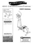
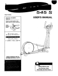
920
S
USER'S MANUAL
Model No. 831.280170
Serial No.
//I
Sedal
l_r
EQUIPMENT
HELPLINE!
1-800-736-6879
Patent Pending
SEARS, ROEBUCK AND CO.,
HOFFMAN ESTATES, IL 60179
www.proform.com
new products, prizes,
fitness tips, and much morel
TABLE OF CONTENTS
IMPORTANT PRECAUTIONS
.............................................................
BEFORE YOU BEGIN ...................................................................
ASSEMBLY ...........................................................................
HOW TO OPERATE THE EXERCISE CYCLE .................................................
MAINTENANCE AND TROUBLE-SHOOTING
.................................................
CONDITIONING GUIDELINES ............................................................
PART LIST ...........................................................................
EXPLODED DRAWING .................................................................
HOW TO ORDER REPLACEMENT PARTS ...........................................
FULL 90 DAY WARRANTY
....................................................
2
2
3
4
8
11
12
14
15
Back Cover
Back Cover
BEFORE YOU BEGIN
Congratulations for selecting the new PROFORIVP 920
S EKG exercise cycle. Cycling is one of the most
effective exemises for increasing cardiovascular fitness, building endurance, and toning the entire body.
The PROFORM" 920 S EKG offers an impressive
array of features to let you enjoy this healthful exercise in the convenience and pdvacy of your home.
HELPLINE at 1-800-736-6879, Monday through
Saturday, 7 a.m. until 7 p.m. Central Time (excluding
holidays). To help us assist you, please note the product model number and serial number before calling.
The model number is 831.280170. The sedal number
can be found on a decal attached to the exercise cycle
(see the front cover of this manual).
For your benefit, read this manual carefully before
you use the exercise cycle. If you have questions
after reading the manual, please call our toll-free
Before reading further, please familiarize yourself with
the parts that are labeled in the drawing below.
Book Holder
Console
Handlebar
Handgdp Pulse Sensor
Seat
FRONT
Adjustment Knob
Adjustment Knob
AdjustmentKnob
Wheel
Pedal/Strap
LEFT SIDE
*No water bottle
is included
REAR
3
ASSEMBLY
Assembly requires two persons. Place all parts of the exercise cycle in a cleared area and remove the packing
materials. Do not dispose of the packing materials until assembly is completed.
Assembly requires the included tools and your own adjustable wrench _
driver _.
and Phillips screw-
Use the part drawings below to identify the small parts used in assembly. The number in parenthesis below
each drawing refers to the key number of the part, from the PART LIST on page 14. The second number refers
to the quantity needed for assembly. Note: Some small parts may have been pre-attached for shipping. If a
part is not in the parts bag, check to see if it has been pre-attached.
M8 Nylon
Locknut (10)-4
M4 x 16mm
Screw (66)-1
MIO Black Nylon
Locknut (63)-4
M8 Split
Washer (70)-4
M6 x 25.4mm Button
Screw (33)-1
MIO x 112mm Carriage Bolt (65)-4
4
M10 Black Split
Washer (50)-3
M10 x 27mm Button
Screw (51)-3
1. Identify the Front Stabilizer (2), which has Wheels (30)
on the ends. While another person lifts the front of the
Frame (1) slightly, attach the Front Stabilizer to the
Frame with two M10 x 112mm Carriage Bolts (65) and
two M10 Black Nylon Locknuts (63). Make sure that
the Front Stabitizer Is turned so the Wheels are not
touching the floor.
2. While another person lifts the back of the Frame (1)
slightly, attach the Rear Stabilizer (3) to the Frame with
two MtO x 112mm Carriage Bolts (65) and two M10
Black Nylon Locknuts (63).
30
65
2
65
3. While another person holds the Upright (13) in the
position shown, connect the Upper Wire Hamess (36)
to the Lower Wire Harness (35). Carefully pull the
upper end of the Upper Wire Hamess to remove
any slack from the Wire Harnesses; make sure that
the connectors do not catch on the indicated rod.
Tum the indicated Adjustment Knob (28) counterclockwise two or three tums to loosen it. Next, pull the Knob,
insert the Upright (13) into the Frame (1), and then
release the Knob. Be careful to avoid pinching the
Wire Harnesses (35, 36). Move the Upright up and
down slightly until the pin on the Knob snaps Into
one of the holes In the Upright. Then, turn the Knob
clockwise until it is tight.
Tighten the M6 x 25.4mm Button Screw (33) Into the
Frame (1) and intothe slotin theside ofthe Upright(13).
4. The Console (16) requires four =D" batterlec (not
included); alkaline batteries are recommended. Press
the tab on the battery cover, and lift off the battery
cover. Insert four batteries into the battery compartment. Make sure that the batteries are oriented as
4
shown by the marldngs Inside the battery compartment. Reattach the battery cover.
Battedes_
5
5. Connect the wire harness on the Handgdp Pulse
Sensor (15) to the indicated wire harness on the
Console (16). Insert both wire hamesses into the opening in the bottom of the Console. Then, insert the metal
tube on the Handgrip Pulse Sensor into the opening in
the bottom of the console. Be careful not to pinch
the wire harnesses.
5
15
Refer to the inset drawing. Tighten an M4 x 16ram
Screw (66) into the indicated bracket on the Console
(16) and into the metal tube on the Handgrip Pulse
Sensor (15).
Metal Tube
15
6. While another person holds the Console (16) in the
position shown, connect the wire harness on the
Console to the Upper Wire Hamess (36). Insert the
excess wire harness into the Upright (13).
Attach the Console (16) to the Upright (13) with three
MIO x 27mm Button Screws (51) and three M10 Black
Split Washers (50). Be careful to avoid pinching the
wire harnesses.
Wire Harness
7. Turn the indicated Adjustment Knob (28) counterclockwise two or three turns to loosen it. Next, pull the Knob,
insert the Seat Post (5) into the Frame (1), and then
release the Knob. Move the Seat Post up and down
slightly until the pin on the Knob snaps into one of
the holes in the Seat Post. Then, turn the Knob clockwise until it is tight,
8. Attach the Seat (12) to the Seat Bracket (6) with four
M8 Nylon Locknuts (10) and four M8 Split Washers
(76). Note: The Nylon Locknuts and the Split Washers
may be pre-attached to the underside of the Seat.
Tum the Seat Adjustment Knob (9) counterclockwise
two or three turns to loosen it. Next, pull the Knob, slide
the Seat Bracket (6) into the top of the Seat Post (5),
and then release the Knob. Move the Seat Bracket
forward and backward slightly until the pin on the
Knob snaps Into one of the holee In the Seat
Bracket. Then, turn the Knob clockwise until it is tight.
6
8
12
9.
Identify the Left Pedal (24), which is marked with an
"L." Using an adjustable wrench, firmly tlg_
the
Left Pedal counterclockwise into the Left Crank Arm
(42). Tighten the Right Pedal (not shown) clockwise
into the Right Crank Arm. Important: Tighten both
Pedals as firmly as possible. After using the
exercise cycle for one week, retighten the
Pedals. For best performance, the Pedals must
be kept tightened.
Adjust the Left Pedal Strap (25) to the desired position, and press the end of the Pedal Strap onto the
tab on the Left Pedal (24). Adjust the Right Pedal
Strap (not shown) in the same way.
42
24
10. Make sure that all parts are properly tightened before you use the exercise cycle. Note: After assembly is
completed, some extra parts may be left over. Place a mat beneath the exercise cycle to protect the floor.
7
HOW TO OPERATE THE EXERCISE CYCLE
HOW TO ADJUST THE SEAT POST
HOW TO ADJUST THE UPRIGHT
For effective exercise, the seat
should be at the
The upright can be
adjusted to the
height that is the
most comfortable for
proper height. As
you pedal, there
should be a slight
bend in your knees
when the pedals
are in the lowest
Seat_sea
t
you. To adjust the
upright, first turn the
indicated knob
counterclockwise
two or three turns to
Post
position. To adjust
_:__
Knob
the height of the
seat, first'turn the
indicated knob counterclockwise two or three turns to
loosen it (if the knob is not loosened enough, it may
scratch the seat post). Next, pull the knob, slide the
seat post to the desired height, and then release the
knob. Move the seat post up and down slightly until
the pin on the knob snaps into one of the holes In
the seat post. Then, turn the knob clockwise until it is
tight.
I
/_Updght
loosen it (if the knob
is not loosened
enough, it may
scratch the updght).
Next, pull the knob,
slide the updght to
the desired height,
and then release
the knob. Move the upright up and down slightly
until the pin on the knob snaps into one of the
holes in the upright. Then, tum the knob clockwise
until it is tight.
HOW TO ADJUST THE SEAT
HOW TO ADJUST THE PEDAL STRAPS
The seat can be
adjusted to the
position that is the
most comfortable
for you. Before
adjusting the seat,
dismount the
exercise cycle; do
not adjust the
seat while you are
slttlng on It. To
adjust the seat, first
tum the indicated knob counterclockwise two or three
tums to loosen it (if the knob is not loosened enough, it
may scratch the seat bracket). Next, pull the knob,
slide the seat to the desired position, and then release
the knob. Move the seat bracket forward and backward slightly until the pin on the knob snaps into
one of the holes in the seat bracket. Then, turn the
knob clockwise until it is tight.
To adjust the pedal
straps, first pull the
ends of the straps
off the tabs on the
pedals. Adjust the
straps to the
desired position,
and press the ends
of the straps back
onto the tabs.
8
Pedal
Strap
Tab ¸
,
°
c
:°'/!
FEATURES OF THE CONSOLE
selected. When the batteries are replaced, it may
be necessary to reeelect the desired unit of measurement.
The easy-to-use console offers a selection of features
designed to help you get the most from your workouts.
When the manual mode of the console is selected, the
resistance of the exercise cycle can be adjusted with a
touch of a button. As you exercise, the console will
provide continuous exercise feedback. You can even
measure your heart rate using the handgdp pulse sensor. The console also offers four certified personal
trainer programs. Each program automatically controls
the resistance of the exercise cycle as it guides you
through an effective workout.
B. Display mode indicators--These indicators show
which display mode is currently shown (scan,
speed, time, distance, resistance level, calories, fat
calories, or heart rate). Note: When the distance is
shown, the word Miles or the letters Kms will
appear; when your speed is shown, the letters MPH
or Km/H will appear.
C. Program profiles--These profiles show how the
resistance of the exercise cycle will change during
personal trainer programs.
CONSOLE DESCRIPTION
Refer to the drawing above. Note: If there Is a thin
sheet of plastic on the face of the console, remove
It.
D. On/Reset button---When the console is off, pressing
this button will rum on the display. When the console
is on, pressing this button will reset the display. This
button is also used to select the unit of measurement for speed and distance (see A at the left).
A. Display--The display features seven modes that
show your current speed, the elapsed time (or the
time remaining in a personal trainer program), the
distance that you have pedaled, the resistance
level, the approximate numbers of calodes and fat
calodes you have bumed (see FAT BURNING on
page 13), and your heart rate (when you use the
handgrip pulse sensor).
E.
Display Mode button_This button is used to select
the display modes. The modes will be selected in
the following order:,scan, speed, time, distance,
resistance level, calories, fat calories, and heart
rate (when the handgdp pulse sensor is used).
F. + and - buttons--These buttons control the resistanca of the exercise cycle.
Note: The console can show speed and distance
in either miles or kilometers. To change the unit
of meaSurement, hold down the On/Reset button
for six seconds. The mode indicators (see B at
the dght) will show which unit of measurement is
G. Program button--This button is used to select the
manual mode and personal trainer programs.
9
sonal trainer program is selected, the display will
show the time remaining in the program instead
of the elapsed time.
B
Tum on the console.
Note: The console requires four "D" batteries (not
included). If you have not installed batteries, refer
to step 4 on page 5 and install batteries.
To turn on the console, press the On/Reset button
or begin pedaling.
B
Select the manual mode.
Each time the console is turned on, the manual
mode will automatically be selected. If a personal
trainer program has been selected, you can
select the manual mode by pressing the Program
button repeatedly until a "P 4" appears in the display and then pressing the Program button once
more.
Ii_R the
Begin
exercising
exercise
cycle.and adjust the resistance of
As you exemlse, adjust the resistance of the
exercise cycle as desired by pressing the + and buttons. There are ten resistance levels; level 10
is the most challenging. Note: After the buttons
are pressed, it will take a few seconds for the
selected settingto be reached.
B
Follow your progress with the display.
When the console is turned
on, the scan
mode wiU be
selected. As
you exemise,
the display will
show your current speed, the elapsed time, the
distance that you have pedaled, the current resistance level, and the approximate numbers of
calodas and fat calories you have bumed (see
FAT BURNING on page 13). In addition, your
heart rate will be shown when you use the handgrip pulse sensor (refer to step 5 at the fight).
The display will change from one mode to the
next every six seconds. Note: Each time the
resistance level changes, the console will show
the resistance level for six seconds. When a per-
10
If desired, you
can select a single mode for
continuous display. Press the
Display Mode
button repeatedly until only the MPH (or KmiH), rime, Miles (or
Kms), Resist., Cals., or Fat Cals. indicator
appears in the display. Make sure that the Scan
indicator does not appear.
E!
Measure your heart rate if desired.
Note: If there are thin sheets of plasUc on the
metal contacts on the handgrlp pulse sensor,
peel off the plastic.
To use the handgdp pulse sensor, place your
hands on the
metal contacts.
Your palms must
Metal
be on the upper
Contacts
contacts and
your fingers
must be touching the lower contacts. Avoid moving your hands. When your pulse is detected, the
heart-shaped indicator in the display will flash
each time your heart beats. After a moment, two
dashes (- -) will appear and then your heart rate
will be shown.
For the most accurate heart rate reading, continue
to hold the handgfipe for about 15 seconds. Note:
When you first hold the handgrips, the display will
show your heart rate continuously for 15 seconds. The display will then show your heart rate
along with the other feedbaok modes.
r_when
you ere finished exere_lng, the console
will automatically turn off after five minutes.
If the pedals are not moved and the console buttons are not pressed for five minutes, the console will automatically turn off to conserve
the batteries.
B
Dudng the program, the resistance of the exercise cycle will automatically change as shown by
the applicable profile on the console. If the currant resistance level is too high or too low, you
can change the resistance level by pressing the +
and - buttons. However, when the current pedod
of the program is completed, the resistance level
will automatically change if a different resistance
setting is programmed for the next pedod.
Tum on the console.
Refer to step 1 on page 10.
B
Select one of the four personal trainer
programs.
Each time the
console is
turned on, the
manual mode
will be selected.
To select a personal trainer
During the program, the display will show the time
remaining in the program. If you continue exemising after the program is completed, the display
will continue to show your exercise feedback.
LP I
B
Refer to step 4 on page 10.
program, press the Program button repeatedly
until a "P 1 ," "P 2," =P 3," or =P 4" appears in the
display.
B
Start the program.
To start the program, simply begin exercising.
Each personal trainer program consists of thirty,
one-minute periods. One resistance setting is programmed for each pedod. (The same resistance
setting may be programmed for consecutive periods.)
11
/
Measure your heart rate if desired.
See step 5 on page 10.
The four profiles on the dght side of the console
show how the resistance of the exercise cycle will
change dudng the personal trainer programs. For
example, profile number 3 shows that the resistance will altemately increase and decrease
throughout program 3.
B
Follow your progress with the display.
r_
when you are finished exercising, the console
will automatically turn off after five minutes.
Refer to step 6 on page 10.
MAINTENANCE
AND TROUBLESHOOTING
Inspect and tighten all parts of the exemise cycle regularly. Replace any worn parts immediately.
• For the most accurate heart rate reading, hold the
metal contacts for about 15 seconds.
To clean the exercise cycle, use a damp cloth and a
small amount of mild soap. Important: To avoid
damage to the console, keep liquids away from
the console and keep the console out of direct
sunlight.
• For optimal performance of the handgdp pulse sensor, keep the metal contacts clean. The contacts
can be cleaned with a soft cloth--never use alcohol,
abrasives, or chemicals.
HOW TO MOVE THE EXERCISE CYCLE
BATrERY REPLACEMENT
To move the exercise cycle, first stand in front of the
exercise cycle, hold the handlebars, and place one
foot on the front stabilizer. Pull the handlebars until
the exercise cycle can be moved on the front wheels.
Carefully move the exercise cycle to the desired location and then lower it.
If the console display becomes dim, the batteries
should be replaced; most console problems are the
result of low batteries. Refer to assembly step 4 on
page 5 for replacement instructions. Note: The console requires four =D" bettades.
HOW TO LEVEL THE EXERCISE CYCLE
After the exercise cycle has
been moved to
the location
where it will be
used, make sure
that both ends of
_ont stabilizer
Leveling
are touching the
Foot
floor. If the exercise cycle rocks
slightly dudng use, tum one or both of the leveling
feet under the front stabilizer until the roddng motion
is eliminated.
HANDGRIP
Handlebars
l/
PULSE SENSOR TROUBLE.SHOOTING
Xe\
• Avoid moving your hands while using the handgdp
pulse sensor. Excessive movement may interfere
with heart rate readings.
Wheel _
• Do not hold the metal contacts too tightly; doing so
may interfere with heart rate readings.
12
CONDITIONING
GUIDELINES
The following guidelines will help you to plan your
exercise program. Remember that proper nutrition
and adequate rest are essential for successful results.
During the first few minutes of exercise, your body
uses easily accessible carbohydrate calories for energy. Only after the first few minutes of exercise does
your body begin to use stored fat calodes for energy.
If your goal is to burn fat, adjust the intensity of your
exercise until your heart rate is near the lowest number in your training zone as you exercise. For maximum fat burning, adjust the intensity of your exercise
until your heart rate is near the middle number in your
training zone as you exercise.
Aerobic Exercise
If your goal is to strengthen your cardiovascular system, your exercise must be =aerobic." Aerobic exercise is activity that requires large amounts of oxygen
for prolonged pedods of time. This increases the
demand on the heart to pump blood to the muscles,
and on the lungs to oxygenate the blood. For aerobic
exercise, adjust the intensity of your exercise until
your heart rate is near the highest number in your
training zone.
EXERCISE INTENSIFY
Whether your goal is to bum fat or to strengthen your
cardiovascular system, the key to achieving the
desired results is to exercise with the proper intensity.
The proper intensity level can be found by using your
heart rate as a guide. The chart below shows recommended heart rates for fat burning, maximum fat
burning, and cardiovascular (aerobic) exercise.
165 155
145 I40
130 I25
Each workout should include the following three pads:
A warm-up, consisting of 5 to 10 minutes of stretching
and light exercise. A proper warm-up increases your
body temperature, heart rata, and circulation in preparation for exercise.
U5
I45
138 130 125 H8
110 103
125
120
115
110 105
95
90
20
30
40
50
70
80
60
WORKOUT GUIDEUNES
Training zone exercise, consisting of 20 to 30 minutes of exercising with your heart rate in your training
zone. (Dudng the first few weeks of your exercise program, do not keep your heart rate in your training
zone for longer than 20 minutes.)
A cool-down, with 5 to 10 minutes of stretching. This
will increase the flexibility of your muscles and will
help to prevent post-exercise problems.
To find the proper heart rate for you, first find your age
at the bottom line of the chart (ages are rounded off to
the nearest ten years). Next, find the three numbers
above your age. The three numbers are your "training
zone." The lowest number is the recommended heart
rate for fat buming; the middle number is the recommended heart rate for maximum fat buming; the highest number is the recommended heart rate for aerobic
exercise.
EXERCISE FREQUENCY
To maintain or improve your condition, plan three workouts each week, with at least one day of rest between
workouts. After a few months of regular exercise, you
may complete up to five workouts each week, if
desired. Remember, the key to success is make exercise a regular and enjoyable part of your everyday life.
Fat Burning
To bum fat effectively, you must exercise at a relatively low intensity level for a sustained )edod of time.
13
EXPLODED DRAWINGmModel NO. 831.280170
Key No. Qty.
1
2
3
4
5
6
7
8
9
10
11
12
13
14
15
16
17
18
19
20
21
22
23
24
25
26
27
28
29
30
31
32
33
34
35
36
37
38
1
1
1
2
1
1
2
2
1
6
1
'1
1
1
1
1
1
1
1
1
2
1
2
1
1
1
1
2
2
2
1
1
1
1
1
1
1
1
Description
Frame
Front Stabilizer
Rear Stabilizer
Rear Endcap
Seat Post
Seat Bracket
Handlebar Endcap
Foam Grip
Seat Adjustment Knob
M8 Nylon Locknut
M6 x 38mm Screw
Seat
Updght
Upright Bushing
Handgdp Pulse Sensor/Handlebar
Console
Left Side Shield
Right Side Shield
Side Shield Cover
Seat Upright Bushing
M8 Push Nut
Reed Switch Clamp
M4 x 5ram Screw
Left Pedal
Left Pedal Strap
Right Pedal
Right Pedal Strap
Adjustment Knob
M6 x 72mm Button Screw
Wheel
Left Front Endcap
Right Front Endcap
M6 x 25,4mm Button Screw
Adjustment Motor
Lower Wire Harness
Upper Wire Harness
Flywheel
Magnet
Rt2OlA
Key No, Qty.
Description
39
40
41
42
43
44
45
• 46
47
48
49
50
51
52
53
54
55
56
57
58
59
60
61
62
63
64
65
66
67
68
69
70
71
72
73
#
#
Flywheel Axle
Flywheel Beadng
=C" Magnet
Left Crank Arm
Reed Switch/Wire
Crank Beadng
M5 Nut
Adjustment Cable
Retum Spdng
Idler Arm
Idler Wheel w/Bearing
M10 Black Split Washer
M10 x 27mm Button Screw
M4 x 25mm Screw
=J" Bolt
Pulley
M10 x 25mm Flat Bolt
Flange Screw
Right Crank Arm
M4 x 7mm Screw
M8 x 47mm Button Bolt
M6 Nut
M8 Nylon Jam Nut
Flywheel Washer
M10 Black Nylon Locl_ut
Idler Washer
M10 x 112mm Carriage Bolt
M4 x 16mm Screw
Leveling Foot
Flywheel Spacer
M8 Flange Nut
M8 Split Washer
M4 x 12mm Round Read Screw
Be_
Motor Washer
User's Manual
Allen Wrench
1
2
1
1
1
1
2
1
1
1
1
3
3
7
1
1
1
2
1
2
1
2
2
1
5
2
4
11
2
1
1
4
2
1
4
1
2
Note: =#" indicates a non-illustrated part, Specifications are subject to change without notice. See the back COver
of this manual for information about ordedng replacement parts,
14
EXPLODED DRAWING---Model No. 831.280170
R12OlA
52
52
71
17
7
66
\
8
3O
14
29
32
35
28
43
31
67
68
62
65
15
SF.,a,
RS
All replacement parts are available for immediate purchase or
special order when you visit your nearest SEARS Service Center.
To request service or to order parts by telephone, call the toll-free
numbers listed at the left.
Model No. 831.280170
QUESTIONS?
When requesting help or service, or ordedng parts, please be
prepared to provide the following information:
If you find that:
• you need help assembling or
operating the PROFORM" 920 S
EKG
• a part Is missing
• or you need to schedule repair
service
• The MODEL NUMBER of the product (831 280170)
• The NAME of the product (PROFORM e 920 S EKG exercise
cycle)
• The KEY NUMBER and DESCRIPTION of the PART (see the
PART LIST and the EXPLODED DRAWING on pages 14 and 15)
call our toll-free HELPMNE
1-800-736-6879
Monday-Saturday, 7 am-7 pm
Central Time (excluding holidays)
REPLACEMENT
PARTS
If parts become worn and need to
be replaced, cell the following tollfree number
1-800-FON-PART
(1-800-366-7278)
I
FULL 90 DAY WARRANTY
I
For 90 days from the date of purchase, if failure occurs due to defect in material or workmanship in this
SEARS BIKE EXERCISER, contact the nearest SEARS Service Center throughout the United States
and SEARS will repair or replace the BIKE EXERCISER, free of charge.
This warranty does not apply when the BIKE EXERCISER is used commercially or for rental purposes.
This warranty gives you specific legal dghts, and you may also have other rights which vary from state
to state.
SEARS, ROEBUCK AND CO., DEPT, 817WA, HOFFMAN ESTATES, IL 60179
Part No. 179660 R1201A
Pdnted in China © 2001 ICON Health & Fitness, Inc,