1
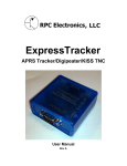
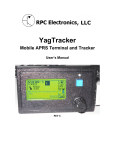
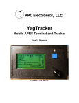
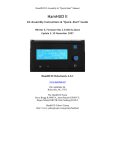
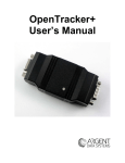
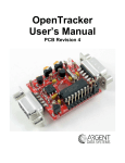
RTrak-Lite
Integrated APRS Tracker
User’s Manual
Revision A
Written By: Jason Rausch KE4%YV
Copyright 2011 RPC Electronics, LLC
Table of Contents
1.
2.
3.
4.
5.
6.
Introduction and Acknowledgments
Package Contents
Device Overview and Specifications
Connections
Getting Started
Basic APRS Programming
• Callsign
• Icon
• APRS Path
• Beacon Rate
7. Major Component Specifications
• OpenTracker 1+
• M%5010HS GPS Chipset
Introduction
Thank you for purchasing an RTrak-Lite! We are pleased that you have decided to
make it part of your amateur radio equipment and hope that it will serve you well for
many years to come. Please take some time to read through this manual and familiarize
yourself with the functions of your new RTrak-Lite and how to operate it properly.
Acknowledgments
Special thanks to the following people for helping make the RTrak-Lite possible:
Scott Miller N1VG
Shaena Hicks KI4UDD
Package Contents
• Your new RTrak-Lite comes with everything required to get started, minus the radio,
antenna and computer for initial programming.
Included Items:
• RTrak-Lite APRS Tracker
• Active GPS Patch Antenna
• 12VDC Lighter Power Cable
• DB9 Serial to 2.5mm Stereo Programming Cable
• CD Containing this manual and specification sheets on key components
Device Overview and Specifications
•
The RTrak-Lite is the only model in the RTrak family that does NOT have an
internal radio/transmitter. The RTrak-Lite requires the end user to interface it to
any VHF/UHF FM radio of their choice. The main advantage to this is the ability
to use a radio with any transmitting power level and have an internal receiver to
check for channel activity before transmitting.
OpenTracker 1+:
The data modem section of the RTrak-Lite is based on the SMT
OpenTracker 1+ platform. The OpenTracker was designed and
programmed by Scott Miller N1VG of Argent Data Systems. The
OT1+ platform is fully open source and a perfect match for the
RTrak-Lite tracker. Firmware upgrades are free for download.
M%5010HS:
The GPS receiving chipset used in the RTrak-Lite. This GPS is a
Sirf-Star III receiver with a fast <60 sec cold start lock time,
measures only 10mm x 10mm in size and runs on a 5V operating
voltage.
Connections
•
There are three main connections that will be used any time the RTrak-Lite is in full
operating mode: Power, GPS Antenna and Radio.
Power
The RTrak-Lite can be powered with any 9-20 VDC source. This makes it perfect for
use in a vehicle, boat or just about any other mobile form of transportation. The power
jack is a standard coaxial 2.1mm I.D. jack with a positive center (tip) polarity
The included lighter cable is perfect for most vehicle applications. In portable or human
power applications, such as a bike or hiking, a battery pack may be used to power the
tracker. A 12VDC gel cell or similar Lithium-Polymer style battery would be sufficient.
GPS
The GPS connection is a standard polarity, SMA female RF connector suited to mate
with the included GPS active patch antenna. Be sure to tighten antenna connector finger
tight. DO NOT use a wrench to torque the connector tight. This is not needed and risks
damage to the connector or main RTrak-Lite board.
Radio
The radio interface is a standard RJ-45 ethernet style connector. All required signals to
connect the tracking to any VHF/UHF FM radio are available at this connector. A
interfacing cable with a pre-installed RJ-45 connector and bare wire ends is included with
the tracker package. For a pinout, please see Appendix A.
Programming Port
The programming port is a stereo 2.5 mm jack used only when the RTrak-Lite needs to
be configured for operation. This is a self-isolating jack that is engaged only when the
programming cable is inserted. Failure to remove this cable during normal operation will
block GPS data from getting to the on-board OpenTracker. The cable must be removed
to restore this internal connection.
Rear Panel
Getting Started
•
Getting started is easy with the RTrak-Lite.
1. Simply connect the included power cable and GPS antenna.
2. Install the programming software included on the RTrak-Lite User’s CD on any
3.
4.
5.
6.
computer with a 9 pin serial port. Note: Some USB>Serial adapters have been
reported to work with this software. Use at your own risk.
Ensure that power to RTrak-Lite is REMOVED.
Connect the programming cable to the RTrak-Lite’s programming port and the
computer’s serial port.
Plug power into the RTrak-Lite.
Start up the RTrak programming software: rtrak-prog.exe. You will see a window
like this:
7. Select the appropriate com port and click Connect.
8. If the software properly reads the RTrak-Lite, the connect window will close and
open up a configuration window containing all of the current settings.
•
When you get to this point, proceed with the following page of Basic APRS
Programming instructions.
Basic APRS Programming
•
Callsign: Use your FCC assigned Amateur Radio callsign for this field
Examples: KE4NYV KI4UDD N1VG
•
Callsign with SSID: The use of an SSID can aid in the multiple use of a single
callsign. The SSID ID will be designated by a dash (-) sign
and a number of 1-15. These SSIDs typically have specific
meaning, so check with your local APRS users for the
SSID that is appropriate for a non-receiving APRS tracker.
Examples: KE4NYV-15 KI4UDD-12 N1VG-9
•
Icon: The icon symbol will tell any receiving station what icon to use when
displaying your position on an APRS map.
Common APRS Icon Symbols
Car
Truck
Van
18 Wheeler
Bike
Hiker
Ambulance
Jeep
RV
Airplane
Boat
•
/>
/k
/v
/u
/b
/[
/a
/j
/R
/’
/Y
Path: The path is used to route your packet as far as you would like it to go,
within reason. You want to make your path fall into the guidelines of your
local area and that is hard to determine through a manual. This manual
will give you some common examples to start with.
Examples: WIDE1-1 WIDE2-2 WIDE1-1,WIDE2-2
•
Beacon Rates: The RTrak-Lite is capable of two beacon schemes.
1. Static Beacon – This method uses a pure timing scheme to beacon at a
constant rate set in programming. This rate cannot be changed unless the
configuration software and cable are used to make the change.
The static beacon rate is set in seconds, meaning 30 = 30 seconds, 60 = 1
minute and so on. A typical static beacon rate is 3-5 minutes.
2. SmartBeaconing™ – This method uses the current GPS data to determine
when to beacon and how often.
There are two main elements to the SmartBeaconing™ algorithm:
•
•
Speed-Adjusted Beacon Rate – Depending on your travel speed, the
beacon rate is either increased or decreased. When traveling faster, the
tracker is covering more ground and beacons more often. When traveling
slower or stopped, the beacon rate is less often since it is not moving far or
may be sitting still.
Cornerpegging – While moving, the SB algorithm is constantly
monitoring the heading of travel. When this degree of heading has
changed past a certain threshold, it triggers a beacon to indicate either a
long steady curve or a direct turn around a corner. The result is a much
more defined track.
•
After all settings have been made, the last step is to write the configuration back to
the RTrak-Lite. Click the “Write” button located in the bottom right of the
configuration window. When the software is completed loading the settings, you will
be asked to click the “OK!” button. The software returns to the main configuration
screen where it can be exited.
•
Power down the RTrak-Lite by removing power from the power jack. Remove the
programming cable and power the unit back up for normal operation. You are now
ready to put your RTrak-Lite into service.
NOTE: Any additional settings can be found in the OpenTracker manual, included on
the RTrak-Lite User’s CD
Major Component Specifications
•
•
OpenTracker 1+
• Operating Voltage
• Operating Current
• Modes
• GPS Interface
DC 6.5-28V or 5VDC Regulated
8 mA Idle, 20 mA Transmitting
1200 bps AFSK
NMEA 4800 bps
M%5010HS
• Receiver Class
• Channel
• Operating Voltage
• Cold Start Lock Time
• Interface
• Sensitivity
• Maximum Altitude
• Operating Current
Sirf-Star III
20
3.25-5.5 VDC
>30 Second
NMEA-0183
-145dBm at Acquisition
60K Feet
30 mA
Appendix A
•
Radio Port Pinout
•
When using the supplied interface cable, the color code in the above table will be
valid. If using an aftermarket cable or hand made cable, verify color code before
using!
If you are powering the RTrak-Lite via the 2.1mm coaxial power jack, the only
required pins of the radio port are: 1, 3, 5 and 6.
•