1
3070 Board Test Systems
System Installation Manual (MS Windows Version)
June 2003
Contents
System Installation Manual (MS Windows Version)
E9970-90001 Rev. H 06/2003
1
MS Windows System Installation Procedure
In this Chapter.............................................................................................................................. 1-1
Referenced Manuals .............................................................................................................. 1-1
Tools Required............................................................................................................................. 1-2
Getting Started ............................................................................................................................. 1-3
Verify Site Preparation Complete.......................................................................................... 1-3
Check for Shipping Damage.................................................................................................. 1-3
Check the Shipment Against the Order Before Uncrating .................................................... 1-3
Un-crate the System............................................................................................................... 1-3
Check the System and the Contents of all Crates and Boxes Against the Order................... 1-3
Setting Up the KVM and Support Arms...................................................................................... 1-5
Introduction............................................................................................................................ 1-5
Install the KVM and Support Arms ....................................................................................... 1-5
Adjust the Support Arm Tension ......................................................................................... 1-15
Setting Up the Strip Printer........................................................................................................ 1-17
Install the Strip Printer Tray ................................................................................................ 1-17
Install the Strip Printer......................................................................................................... 1-17
Preparing the Testhead............................................................................................................... 1-18
Install the Footswitch........................................................................................................... 1-18
Install the Probe and Probe Cradle ...................................................................................... 1-19
Install the Fixture Pull-Down Label -- Non-English Only .................................................. 1-19
Attach the Site LAN Cable .................................................................................................. 1-20
Powering the PDU and Controller ............................................................................................. 1-21
Supply Power to the PDU.................................................................................................... 1-21
Switch on the Controller ...................................................................................................... 1-21
Configuring the System to a Network ................................................................................. 1-22
Logon as service3070 to Complete the Installation .......................................................... 1-22
© Agilent Techonolgies 2001–2003
Agilent 3070 System Installation Manual (MS Windows Version)
i
Table of Contents
Installing a Support Bay and Instrument Rack .......................................................................... 1-23
Introduction.......................................................................................................................... 1-23
Install the Testhead Module Umbilical Cable(s) (307X Only)............................................ 1-23
Install the GPIB Cables (307X Only) .................................................................................. 1-24
Setting-Up Other Hardware ....................................................................................................... 1-27
Install a Pay-Per-Use (PPU) Button Adapter....................................................................... 1-27
Setup the Testhead for Automation ..................................................................................... 1-30
Install AccessPlus Cables .................................................................................................... 1-32
Enabling the Testhead................................................................................................................ 1-33
Boot the Testhead ................................................................................................................ 1-33
Troubleshooting Testhead Boot........................................................................................... 1-33
Check the System Config File ............................................................................................. 1-34
Verifying the Vacuum Subsystem ............................................................................................. 1-36
Introduction.......................................................................................................................... 1-36
Install the Vacuum Manifold ............................................................................................... 1-36
Connect the Compressed Air ............................................................................................... 1-36
Check the Vacuum Actuation System ................................................................................. 1-36
Troubleshooting ................................................................................................................... 1-37
Verifying the Testhead............................................................................................................... 1-39
Run AutoAdjust All ............................................................................................................. 1-39
Run Full Diagnostics ........................................................................................................... 1-39
Completing the Installation........................................................................................................ 1-40
Verify Strip Printer .............................................................................................................. 1-40
System Printer / Plotter ........................................................................................................ 1-40
Stabilize the Testhead .......................................................................................................... 1-40
Reinstall Covers ................................................................................................................... 1-40
Make System Recovery and Backup Tapes......................................................................... 1-40
Turn System Administration Over to the Customer ............................................................ 1-40
Fill Out the System Support Log ......................................................................................... 1-40
Maintenance Records........................................................................................................... 1-41
About ScanWorks ................................................................................................................ 1-41
Installation Billing Information ........................................................................................... 1-41
© Agilent Techonolgies 2001–2003
Agilent 3070 System Installation Manual (MS Windows Version)
ii
Table of Contents
In Case of Difficulty .................................................................................................................. 1-42
Shipping Damage or Incorrect Shipment............................................................................. 1-42
Network, System Administration, or Test Server Help ....................................................... 1-42
Optional Agilent Performance Port Actuator Control System (ACS)................................. 1-42
Vacuum Subsystem.............................................................................................................. 1-42
Additional Resources ........................................................................................................... 1-42
2
MS Windows System Installation Reference
In this Chapter.............................................................................................................................. 2-1
Referenced Manuals .............................................................................................................. 2-1
Introduction............................................................................................................................ 2-1
Logging-On as service3070 ......................................................................................................... 2-2
Display the Logon Status from a Current Login.................................................................... 2-2
Logon as service3070 to Complete the Installation ............................................................ 2-2
The Root Directory Environment Variable ................................................................................. 2-3
Introduction............................................................................................................................ 2-3
Determine the Value of the Root Directory Environment Variable ...................................... 2-3
Use of the Root Directory Environment Variable in a BT-BASIC Window ........................ 2-4
Use of the Root Directory Environment Variable in a Korn Shell Window ......................... 2-5
Use of the Root Directory Environment Variable in a DOS Command Prompt Window .... 2-6
Directory Descriptions ................................................................................................................. 2-7
Editing Files ................................................................................................................................. 2-8
Front-Slashes versus Back-Slashes in Command Lines Containing File Paths .................... 2-8
Use BT-BASIC ...................................................................................................................... 2-8
How to Edit the System Config File to Match the Testhead Configuration.......................... 2-9
How to Resolve the Standard Config File from the System Config File ............................ 2-10
MS Windows Quick Reference ................................................................................................. 2-15
BT-BASIC Quick Reference ..................................................................................................... 2-16
Korn Shell Quick Reference ...................................................................................................... 2-17
vi and vi Editor Quick Reference .............................................................................................. 2-20
© Agilent Techonolgies 2001–2003
Agilent 3070 System Installation Manual (MS Windows Version)
iii
Table of Contents
Codewords & Software License Keys ....................................................................................... 2-24
Introduction.......................................................................................................................... 2-24
Installing Codewords & Software License Keys ................................................................. 2-24
Verify Installed Codewords ................................................................................................. 2-24
Compile the Two Config Files............................................................................................. 2-24
System Config File Specifics..................................................................................................... 2-26
Introduction.......................................................................................................................... 2-26
Location of the System Config File..................................................................................... 2-26
Edit the System Config File................................................................................................. 2-26
The "Official" and "Actual" System Config Files ............................................................... 2-26
To Repair a Corrupt System Config File ............................................................................. 2-26
Descriptions of Some Statements in the System Config File .............................................. 2-27
Standard Config File Specifics .................................................................................................. 2-29
Introduction.......................................................................................................................... 2-29
Location of the Standard Config File .................................................................................. 2-29
The Board Config File ......................................................................................................... 2-29
Standard Config File Syntax Similarities to and Differences from the System Config File2-29
Statements Allowed in the Standard, System, and Board Config Files............................... 2-30
Statements Allowed in the System Config File ................................................................... 2-30
Descriptions of Some Statements in the Standard Config File............................................ 2-30
Compiling the System and Standard Config Files..................................................................... 2-35
The bootptab File ....................................................................................................................... 2-36
Hardware Addresses ............................................................................................................ 2-36
IP Addresses ........................................................................................................................ 2-37
The hosts File............................................................................................................................. 2-38
Test Device Communication ............................................................................................... 2-38
Device Files ............................................................................................................................... 2-40
Introduction.......................................................................................................................... 2-40
Location of Device Files...................................................................................................... 2-40
If a DUT Power Supply is Replaced.................................................................................... 2-40
DUT Power Supply Device Files......................................................................................... 2-40
© Agilent Techonolgies 2001–2003
Agilent 3070 System Installation Manual (MS Windows Version)
iv
Table of Contents
Vacuum Control......................................................................................................................... 2-41
Location of Vacuum Control Statements............................................................................. 2-41
Vacuum Control Specifics ................................................................................................... 2-41
Rotating the Testhead ................................................................................................................ 2-42
Testhead Cards........................................................................................................................... 2-43
If Changing a ControlXT/XTP or System Card .................................................................. 2-43
DUT Power Supplies ................................................................................................................. 2-45
Voltage Ranges .................................................................................................................... 2-45
DUT Power Supplies Allowed ............................................................................................ 2-45
Module Mappings ................................................................................................................ 2-45
GPIB Addresses and Device Files ....................................................................................... 2-46
Controller Cables and Devices .................................................................................................. 2-49
X2000 Controller ................................................................................................................. 2-49
X2100 Controller ................................................................................................................. 2-49
IPC Controller...................................................................................................................... 2-49
Private LAN and Serial Port MUX............................................................................................ 2-59
Introduction.......................................................................................................................... 2-59
IP Addresses ........................................................................................................................ 2-59
Hardware Addresses ............................................................................................................ 2-59
Verify Communication to the Testhead............................................................................... 2-59
Serial Port MUX .................................................................................................................. 2-60
Troubleshooting LAN Port Connections ................................................................................... 2-61
Simple Solution.................................................................................................................... 2-61
Setting the LAN Connection Properties .............................................................................. 2-61
Installing Drivers and Configuring LAN Ports.......................................................................... 2-62
Installing the Graphics and LAN Drivers ............................................................................ 2-62
© Agilent Techonolgies 2001–2003
Agilent 3070 System Installation Manual (MS Windows Version)
v
1
MS Windows System Installation Procedure
E9970-90001 Rev. H 06/2003
CAUTION
system should only be installed by an Agilent
✸This
3070 service-trained customer engineer (CE).
Testhead boot conflicts may occur if this system is
on a network with 3070 UNIX controllers with IP
addresses other than in the 10.3.112.XX series.
See Configuring the System to a Network on
page 1-22 for more information.
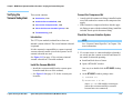
In this Chapter...
© Agilent Technologies 2001–2003
■
Tools Required, 1-2
Referenced Manuals
■
Getting Started, 1-3
These manuals are referenced in this manual:
■
Setting Up the KVM and Support Arms, 1-5
■
Setting Up the Strip Printer, 1-17
■
Preparing the Testhead, 1-18
■
Powering the PDU and Controller, 1-21
■
Installing a Support Bay and Instrument Rack, 1-23
■
Setting-Up Other Hardware, 1-27
■
Enabling the Testhead, 1-33
■
Verifying the Vacuum Subsystem, 1-36
■
Verifying the Testhead, 1-39
■
Completing the Installation, 1-40
■
In Case of Difficulty, 1-42
Agilent 3070 System Installation Manual (MS Windows Version)
■
■
■
Agilent 3070 Site Preparation Manual
(E9900-90045).
Administering Agilent 3070 MS Windows Systems.
Agilent 3070 / 79000 Repair Manual.
CAUTION
customers change Regional Options on the
✸ Some
controller to set Your locale to their geographic
location. Is is alright to do this as long as you
don’t change Decimal symbol. The Decimal symbol
must remain a period (.); it cannot be changed to a
comma (,) or Board Consultant will damage
testplans.
1-1
Chapter 1: MS Windows System Installation Procedure: Tools Required
Tools Required
These tools are needed in addition to the tools supplied
with the system shipment:
■
BNC-to-dual banana coaxial cable 11001-60001,
for Diagnostics,
■
BNC(F)-to-BNC(F) (barrel) connector
1250-0080, for Diagnostics,
■
Pin Verification Fixture (PVF) for Diagnostics:
• E3771B for one-module systems,
• E4033B for one to four-module systems,
• N4355A 2-Bank No-Wire Interface PVF (only
required with No-Wire fixture,)
© Agilent Technologies 2001–2003
■
T10 & T20 Torx drivers,
■
#2 Phillips or Posi screwdriver,
■
1/4-inch flat blade screwdriver,
■
5- and 10-mm hex key wrenches,
■
Diagonal-cutters to cut straps,
■
Utility knife to open boxes,
■
7/16-inch and 9/16-inch, 3/8-inch square-drive
sockets,
■
6-inch-long, 3/8-inch square-drive extension,
■
3/8-inch square-drive ratchet,
■
Cordless drill – 14.4 Volt, 3/8-inch drill / driver
kit.
Agilent 3070 System Installation Manual (MS Windows Version)
1-2
Chapter 1: MS Windows System Installation Procedure: Getting Started
Getting Started
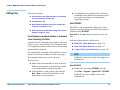
Verify Site Preparation Complete
Typically, the Agilent 3070 Site Preparation Manual
(03066-90114) is delivered to the customer by an
Agilent representative one month prior to system
shipment. A copy can also be found included with the
system shipment. From the site prep. manual:
1 View the customer's completed site preparation
checklist.
2 Ask the customer for a copy of the system plan
drawing or have them select the appropriate layout
from Chapter 3.
Check for Shipping Damage
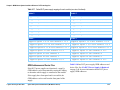
Check the System and the Contents of all Crates
and Boxes Against the Order
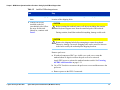
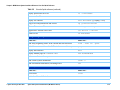
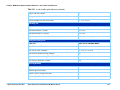
For 3070 systems, the label on the lower right corner of
the rear of the testhead cradle identifies the module
capacity as shown in Table 1-1.
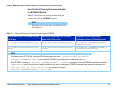
Table 1-1
Label Contains Text
Module Capacity
E9900
4
E9998
2
E9997
1
If damage is found, contact Agilent’s Manufacturing
Test Business Unit, Order Administration:
■
Inside the United States call (970) 679-2261.
■
Outside the United States call (970) 679-3155.
Check the Shipment Against the Order Before
Uncrating
Un-crate the System
Follow the un-crating instructions attached to the pallet
ramp.
The testhead label identifies the module capacity
NOTE
Testheads with capacities for more than one
module can be configured with fewer modules.
Additional modules can be added later.
Check that:
■
A support bay is included with four-module
systems to hold DUT power supplies.
■
The strip printer, tape cartridges, licenses, and
documentation is included.
■
The bag on the testhead includes:
• A pod key,
© Agilent Technologies 2001–2003
Agilent 3070 System Installation Manual (MS Windows Version)
1-3
Chapter 1: MS Windows System Installation Procedure: Getting Started
• A probe cradle,
• Certificates of calibration,
• A Certificate of Hardware Address for the
System Card, and
• Configuration printouts.
■
The bag on the testhead cradle includes:
• An Agilent 3070 Family Site Preparation
Manual, (03066-90114)
• Some tools,
• A female quick-disconnect compressed air
fitting, and
• An Installation Kit 03066-69902 (it contains
various tools and parts.)
© Agilent Technologies 2001–2003
Agilent 3070 System Installation Manual (MS Windows Version)
1-4
Chapter 1: MS Windows System Installation Procedure: Setting Up the KVM and Support Arms
Setting Up the KVM
and Support Arms
This section contains:
■
Introduction, 1-5
■
Install the KVM and Support Arms, 1-5
■
Adjust the Support Arm Tension, 1-15
Introduction
The default location for the KVM (Keyboard, Video
Monitor, Mouse) installation is on the right side of the
testhead, when facing the testhead from the front.
The customer can be accommodated if a preference
exists for having the KVM on the left side. To do this,
the pod cover(s) must be removed, then the KVM
wiring must be re-routed.
Install the KVM and Support Arms
Follow the instructions given in Table 1-2. Additionally,
Figure 1-2 on page 1-12 shows the right side
installation detail, and Figure 1-3 on page 1-13 shows
the left side installation detail.
© Agilent Technologies 2001–2003
Agilent 3070 System Installation Manual (MS Windows Version)
1-5
Chapter 1: MS Windows System Installation Procedure: Setting Up the KVM and Support Arms
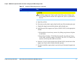
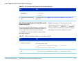
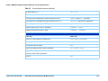
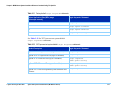
Table 1-2
Install the KVM and support arms
Task
Step
1 Remove the two shipping
bolts.
Do this so that the testhead can be rotated. Figure 1-1 on page 1-11 shows the
location of the shipping bolts.
2 If the KVM will be
installed on the left
(non-default) side, follow
the steps for this task.
Otherwise, continue with
Task 3.
CAUTION
rotating the testhead, remove all objects including the monitor
✸Before
and keyboard support arms from the rotational path of the testhead.
During rotation, should the testhead hit anything, damage could result.
CAUTION
the shipping bolts before attempting to rotate the testhead.
✸Remove
Otherwise, damage can result. Shipping bolts can be stored for later use
in the holes used by the testhead pallet shipping brackets.
Remove pod cover:
a If testhead connectors (BNC) are visible over a pod cover, rotate the
testhead about 10 degrees to allow the pod cover to be removed.
Apply PDU power to activate the testhead rotation switch. See Powering
the PDU and Controller on page 1-21.
b Use a T20 Torx driver to remove the pod-cover screws and then remove the
pod cover.
c Remove power to the PDU if connected.
© Agilent Technologies 2001–2003
Agilent 3070 System Installation Manual (MS Windows Version)
1-6
Chapter 1: MS Windows System Installation Procedure: Setting Up the KVM and Support Arms
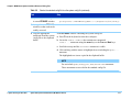
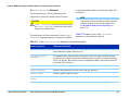
Table 1-2
Install the KVM and support arms (continued)
Task
3 Install the support arms:
Step
CAUTION
the support arm T-piece to the front of the system. Damage may
✸Install
occur during testhead rotation if the support arm T-piece is positioned to
the rear.
a Open the pod door.
b If present, pry the plastic square plug from the top of the mounting arm post.
c Unpack the support arms and the monitor and keyboard trays.
d Install the post of the support arm T-piece (E9900-10245), in the appropriate
column.
1) If the pod door is in the way, remove it by lifting it up, then out. Replace
it when done.
2) Secure the post using a 1/4-inch hex key wrench, two each cap screws
(3030-1044), and lock washers (2190-0963). For 307X, 317X and 327X
systems, use the top and middle screw holes.
e Insert the 13-cm (5-inch) extension riser (E9900-10246), into the hole of the
support arm T-piece that is farthest from the operator.
f If needed, install the square plastic cap in the top of the unused support arm
column.
© Agilent Technologies 2001–2003
Agilent 3070 System Installation Manual (MS Windows Version)
1-7
Chapter 1: MS Windows System Installation Procedure: Setting Up the KVM and Support Arms
Table 1-2
Install the KVM and support arms (continued)
Task
Step
4 Install the keyboard tray:
a Insert the keyboard support arm E9900-10248, in the hole in the support
arm T-piece.
b Install the keyboard tray E9900-10247, on the keyboard support arm using a
Phillips or Posi screwdriver and four flat-head screws, 3030-0219, in the
end of the arm:
5 Position the KVM:
■
Choose one of the center sets of holes for mounting. Other mounting hole
sets can be selected at the customer’s request.
■
Install the keyboard tray so that the tilt adjuster knob can be adjusted
from the front of the keyboard.
a Unpack the keyboard and mouse and place them on the keyboard tray.
b Place the plastic keyboard overlay on the keyboard.
c Install the monitor support arm.
d Install the monitor tray on the support arm.
e Unpack the video monitor, then mount it on the support arm with its
included screws.
f Locate the mouse and mouse pad, then place them on the keyboard tray.
© Agilent Technologies 2001–2003
Agilent 3070 System Installation Manual (MS Windows Version)
1-8
Chapter 1: MS Windows System Installation Procedure: Setting Up the KVM and Support Arms
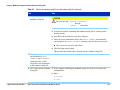
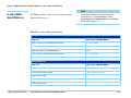
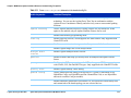
Table 1-2
Install the KVM and support arms (continued)
Task
6 Route the KVM cables:
Step
CAUTION
the KVM cables are not routed with enough slack, they can be
✸Ifdamaged
when the support arms are adjusted. Figure 1-4 on page 1-14
describes this further.
NOTE
The keyboard and mouse is shipped with long enough cables to
accommodate installation on the left side.They are folded back on
themselves in the testhead cable trough (identified in Figure 1-1 on
page 1-11).
For 307X and 317X systems, a second video monitor cable is
pre-installed to accommodate KVM installation on the left side.
For 327X systems, the existing video monitor cable is long enough to
reach to the left side. Re-route it through the testhead cable troughs. Cut
cable ties inside the pod, if necessary.
It may be necessary to obtain a 8120-1763 power cord extension cable to
connect power from the PDU to the video monitor. Route the power
cable through the testhead cable trough.
• Route the KVM cables through the support arm cable troughs.
© Agilent Technologies 2001–2003
Agilent 3070 System Installation Manual (MS Windows Version)
1-9
Chapter 1: MS Windows System Installation Procedure: Setting Up the KVM and Support Arms
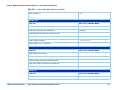
Table 1-2
Install the KVM and support arms (continued)
Task
Step
7 Connect the KVM cables:
NOTE
The USB connectors on (the left side of) the video monitor are not used.
a Remove the cover from the rear of the video monitor, then connect the
power and signal cables.
b Replace the rear cover.
c Connect the keyboard and mouse cables.
8 Install the barcode scanner
cables:
NOTE
a Insert the bar code scanner cable between the keyboard cable and the
keyboard extension cable.
b Route the bar code scanner cables through the support arm cable troughs.
Perform this task only if
installing an optional
barcode scanner.
Otherwise, continue
with Task 9.
© Agilent Technologies 2001–2003
9 Tidy and secure all cables.
Use new cable ties where necessary.
10 Replace pod cover and
door.
Re-install the pod door and use a T20 Torx driver to replace the pod cover
screws.
Agilent 3070 System Installation Manual (MS Windows Version)
1-10
Chapter 1: MS Windows System Installation Procedure: Setting Up the KVM and Support Arms
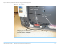
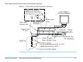
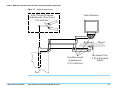
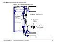
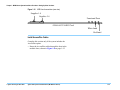
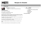
Figure 1-1
Rear of testhead
Strip printer cable coiled
under testhead
Bags of manuals
and parts
Shipping bolt and bracket
on each side of testhead
© Agilent Technologies 2001–2003
Agilent 3070 System Installation Manual (MS Windows Version)
cable trough
1-11
Chapter 1: MS Windows System Installation Procedure: Setting Up the KVM and Support Arms
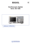
Figure 1-2
KVM and support arm detail for the right side of the testhead
Support Arm Tension
Adjustments (Top View)
(1/4-inch hex)
Riser under
Monitor Arm
Video Monitor
(Flat Panel Display)
Keyboard Arm
on bottom
Monitor Arm
on top
L
Support Arm
T- piece
L
S
Right Pod
Cables Troughs
Short, Medium, Long
M
Keyboard
Mouse
M
Keyboard Tray
Tilt Adjustment
Post Screw Holes
Use top and bottom for 307X or 317X,
middle and bottom for 327X
T-piece post inside column
© Agilent Technologies 2001–2003
Agilent 3070 System Installation Manual (MS Windows Version)
1-12
Chapter 1: MS Windows System Installation Procedure: Setting Up the KVM and Support Arms
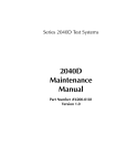
Figure 1-3
KVM and support arm detail for the left side of the testhead
Top View of Support Arm
T-piece
Video Monitor
(Flat Panel Display)
Monitor Arm
(top and rear)
Mouse
Keyboard Arm
(bottom and front)
Riser under
Monitor Arm
Keyboard
Cables
Post Screw Holes
Use top and bottom for 307X or 317X,
middle and bottom for 327X.
Support Arm
T- piece
Left side
of testhead
T-piece post inside column
© Agilent Technologies 2001–2003
Agilent 3070 System Installation Manual (MS Windows Version)
1-13
Chapter 1: MS Windows System Installation Procedure: Setting Up the KVM and Support Arms
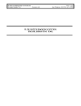
Figure 1-4
Allow enough slack when routing cables
Leave slack here so
cables are not damaged
when support arm
is adjusted.
© Agilent Technologies 2001–2003
Agilent 3070 System Installation Manual (MS Windows Version)
1-14
Chapter 1: MS Windows System Installation Procedure: Setting Up the KVM and Support Arms
Adjust the Support Arm Tension
There are two types of support arm tension adjustments:
vertical and horizontal.
Table 1-3
Use Table 1-3 on page 1-15 and Figure 1-5 on
page 1-16 to adjust the support arm tension.
Adjust the support arms
Task
Step
1 Adjust the support arm
vertical tension:
• Use a 1/4-inch hex key wrench to adjust the monitor and keyboard support
arm vertical tension adjustment screws:
Turn the screw clockwise to make the arm tension harder, and
counterclockwise to make the arm tension easier.
These screws are approximately 48 turns stop-to-stop.
2 Adjust the support arm
horizontal tension:
© Agilent Technologies 2001–2003
• Use a 3/32-inch hex key wrench to adjust the joints in the support arms to a
firm but movable tension.
Agilent 3070 System Installation Manual (MS Windows Version)
1-15
Chapter 1: MS Windows System Installation Procedure: Setting Up the KVM and Support Arms
Figure 1-5
Adjust the support arms
Arm Vertical Tension
Adjustments (Top View)
(1/4-inch hex)
Video Monitor
Keyboard
Arm Horizontal
Adjustments
(3/32-inch hex)
Mouse
Keyboard Tray
Tilt Adjustment
(knob)
Pod
© Agilent Technologies 2001–2003
Agilent 3070 System Installation Manual (MS Windows Version)
1-16
Chapter 1: MS Windows System Installation Procedure: Setting Up the Strip Printer
Setting Up the Strip
Printer
This section contains:
■
Install the Strip Printer Tray, 1-17
■
Install the Strip Printer, 1-17
Install the Strip Printer Tray
Unpack the strip printer tray and install it in the testhead
column opposite the monitor and keyboard.
A plastic cover may need to be pried out of the top of
the column first.
Install the Strip Printer
1 Unpack the strip printer and place it on the strip
printer tray.
2 Connect the pre-routed power and data cables.
NOTE
To install the strip printer on the left side, re-route
the power and data cables through the testhead
cable trough.
© Agilent Technologies 2001–2003
Agilent 3070 System Installation Manual (MS Windows Version)
1-17
Chapter 1: MS Windows System Installation Procedure: Preparing the Testhead
Preparing the
Testhead
This section contains:
■
Install the Footswitch, 1-18
■
Install the Probe and Probe Cradle, 1-19
■
Install the Fixture Pull-Down Label -- Non-English
Only, 1-19
■
Attach the Site LAN Cable, 1-20
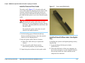
Figure 1-6
Location of the footswitch and leveling foot
Install the Footswitch
NOTE
With software revision 3070 05.20p and later, the
footswitch must be connected to the system. The
footswitch must be pressed to lock fixtures on the
testhead.
Footswitch Cable coiled
under front of testhead
Testhead Leveling Foot
1 Locate the footswitch and cable that are coiled on the
front of the testhead cradle.
See Figure 1-6 for locations.
2 Unpack the footswitch and place it on the floor in
front of the testhead.
© Agilent Technologies 2001–2003
Agilent 3070 System Installation Manual (MS Windows Version)
1-18
Chapter 1: MS Windows System Installation Procedure: Preparing the Testhead
Install the Probe and Probe Cradle
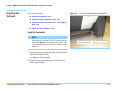
Figure 1-7
Probe cradle (E9900-66400)
The probe cradle (Figure 1-7) is located on the pod
cover of the testhead as shipped from the factory. If the
customer wants the probe in a different location, an
extra strip of sticky-backed hook-and-loop fastener is
provided with the system so you can re-locate the probe
cradle.
WARNING
not place the probe cradle where it could
✸Do
interfere with an overhanging test fixture, thereby
presenting a pinch hazard between the fixture and
the probe cradle.
Do not place the probe cradle where it could
interfere with testhead rotation.
1 Peel the backing paper off the hook-and-loop
fastener and affix the fastener where the customer
wants it (see the Warning above).
2 Move the probe cradle to the new location:
a Rotate the cradle sideways to separate the
fastener.
If installing the system in an English-speaking country,
skip this step.
b Press the probe cradle firmly onto the
hook-and-loop fastener you just installed.
1 Locate the Fixture Pull-down Air Labels
(E9900-84316).
3 Unpack the probe and insert it in the probe cradle.
© Agilent Technologies 2001–2003
Install the Fixture Pull-Down Label -- Non-English
Only
Agilent 3070 System Installation Manual (MS Windows Version)
2 Choose the label that is of the correct language for
the location and apply it over the English text that is
silk-screened on the rear of the testhead near the
compressed air connectors.
1-19
Chapter 1: MS Windows System Installation Procedure: Preparing the Testhead
Attach the Site LAN Cable
Complete this instruction only if the system will be
connected to a network.
• Connect the RJ45 plug from the site Ethertwist LAN
cable to the RJ45 coupler at the rear of the pod.
NOTE
An RJ45 coupler should be visible from the rear
of the controller’s pod. It should not be necessary
to remove the pod cover to attach the site LAN
cable.
© Agilent Technologies 2001–2003
Agilent 3070 System Installation Manual (MS Windows Version)
1-20
Chapter 1: MS Windows System Installation Procedure: Powering the PDU and Controller
WARNING
Powering the PDU
and Controller
This section contains:
■
Supply Power to the PDU, 1-21
■
Switch on the Controller, 1-21
■
Configuring the System to a Network, 1-22
■
Logon as service3070 to Complete the Installation,
1-22
Supply Power to the PDU
NOT open the PDU for any reason.
✸ DO
Voltages capable of causing injury or death are
present inside the PDU, even with the switches
off.
2 Switch on the Mains Disconnect Switch:
The PDU has two switches, both of which are
accessible from the rear of the pod:
■
One is the green Switched Circuits Enabled rocker
switch that enables power to the testhead – DO
NOT switch this one on yet.
■
The other is the large, red rotary Mains Disconnect
Switch that enables power to the PDU outlets,
video monitor, and system controller – switch
only this one on now.
CAUTION
testhead power before connecting or
✸Disconnect
disconnected testhead cables. Otherwise, damage
can result.
1 Connect the PDU power cable to the power source:
Instructions for connecting power are given in the
Agilent 3070 / 79000 Family Site Preparation
Manual 03066-90114, which is shipped in print with
the system.
NOTE
The PDU is not serviceable; if it is defective, it
must be replaced.
© Agilent Technologies 2001–2003
Agilent 3070 System Installation Manual (MS Windows Version)
Switch on the Controller
1 Switch on the video monitor.
2 Open the pod door and switch on the controller.
NOTE
A line of random characters may be printed on the
strip printer. This is normal and should be ignored.
1-21
Chapter 1: MS Windows System Installation Procedure: Powering the PDU and Controller
NOTE
If the MS Windows registration key is needed, it
can be found on the testhead controller after
removing the pod cover.
Configuring the System to a Network
This is usually done with the assistance of the site
network administrator and the Agilent systems engineer
(SE). Either:
■
Configure the network now OR
■
Close the configuration window(s), and configure
the system to a network later.
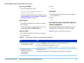
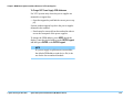
Logon as service3070 to Complete the
Installation
If it should be necessary to change the logon:
1 Press together <CTRL> <Alt> <Delete>.
2 Click Log Off.
Wait for the log off, then follow the on-screen
instructions to log back on.
3 Enter the logon information:
■
Logon Name = service3070
■
Default Password = service
Instructions for configuring the system to a network can
be found in Administering Agilent 3070 MS Windows
Systems (shipped in paper with the system).
NOTE
If you are setting up a network with other UNIXbased 3070 systems, be aware that the IP address
of 3070 UNIX systems changed from the HP
15.3.112.XX series to the Agilent 10.3.112.XX
series. This occurred with the 3070 UNIX
software release B.03.80.
© Agilent Technologies 2001–2003
Agilent 3070 System Installation Manual (MS Windows Version)
1-22
Chapter 1: MS Windows System Installation Procedure: Installing a Support Bay and Instrument Rack
Installing a Support
Bay and Instrument
Rack
This section contains:
■
Introduction, 1-23
■
Install the Testhead Module Umbilical Cable(s)
(307X Only), 1-23
■
Install the GPIB Cables (307X Only), 1-24
Introduction
Complete instructions in this section if installing a
support bay or instrument rack.
If an instrument rack is included containing instruments
requiring GPIB control, see Install the GPIB Cables
(307X Only) on page 1-24.
CAUTION
proper ESD precautions while performing
✸Follow
tasks in this section.
Remove power to the testhead by powering-off
the PDU to prevent electrical damage when
connecting cables.
Install the Testhead Module Umbilical Cable(s)
(307X Only)
NOTE
Umbilical cables consist of DUT power supply
wires, a ground wire, coaxial functional port
wires, and PDU branch control wires.
One umbilical cable is used per testhead module.
Route each umbilical cable directly through the
door of the respective testhead module (cabling no
longer passes through a cable clamp panel in the
testhead).
Reference Figure 1-8 on page 1-25 for these steps:
1 Apply PDU power, rotate the testhead to the service
position, then remove PDU power.
CAUTION
the shipping bolts before attempting to
✸ Remove
rotate the testhead. Otherwise, damage can result.
Before rotating the testhead, remove all objects,
including the monitor / keyboard support arms,
from the rotational path. Damage could result if
the testhead hits anything during rotation.
2 Remove the testhead module door locking bracket.
© Agilent Technologies 2001–2003
Agilent 3070 System Installation Manual (MS Windows Version)
1-23
Chapter 1: MS Windows System Installation Procedure: Installing a Support Bay and Instrument Rack
3 Locate the two access plates on a testhead module
door.
4 Use a T20 Torx driver to loosen the plate covering
the smaller hole then turn the plate around to expose
the hole.
NOTE
The smaller hole is for the umbilical cable; the
larger hole is for the optional AccessPlus cables.
CAUTION
multiple racks or bays are installed containing
✸ Ifequipment
needing GPIB control, connect the
GPIB cabling as shown in Figure 1-9 on
page 1-26.
If the cable connections fork, GPIB errors may
occur.
5 With the testhead module door open, connect all
umbilical cable DUT power supply connectors to the
ASRU Card.
See Figure 1-14 on page 1-32 for the ASRU card
connectors.
6 Connect the ground wire to the ground lug on the
side wall of the testhead module.
7 Connect both of the white coaxial cables to the
functional ports on the ASRU card. See Figure 1-14
on page 1-32 for the ASRU card connectors.
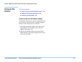
Install the GPIB Cables (307X Only)
• Route the GPIB cable from the support bay, and connect the GPIB cable plug to the controller’s GPIB
card port.
© Agilent Technologies 2001–2003
Agilent 3070 System Installation Manual (MS Windows Version)
1-24
Chapter 1: MS Windows System Installation Procedure: Installing a Support Bay and Instrument Rack
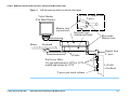
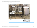
Figure 1-8
Cable the testhead to the support bay
Module Door Locking Bracket
Module 0
Module 1
Vacuum Manifold
Module 2
Optional Support Bay
Module 3
Module Umbilical
Cables
GPIB
Cable
Cable Clamp Panel
Aux Aux Aux Aux Aux Aux
1
© Agilent Technologies 2001–2003
Agilent 3070 System Installation Manual (MS Windows Version)
0
Aux Aux
2
3
1-25
Chapter 1: MS Windows System Installation Procedure: Installing a Support Bay and Instrument Rack
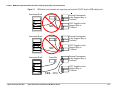
Figure 1-9
GPIB cables to an instrument rack, support bay, and controller. DO NOT allow the GPIB cabling to fork
Instrument Rack
Controller
VXI
Mainframe
Instrument 1
Instrument 2
Instrument Rack
NO
Controller
VXI
Mainframe
Instrument 1
Instrument 2
Instrument Rack
DUT Supplies in the
Support Bay or
Testhead
External Instruments
in the Support Bay or
Testhead
NO
DUT Supplies in the
Support Bay or
Testhead
Controller
External Instruments
in the Support Bay or
Testhead
VXI
Mainframe
Instrument 1
Instrument 2
YES - 3070
© Agilent Technologies 2001–2003
External Instruments
in the Support Bay or
Testhead
Agilent 3070 System Installation Manual (MS Windows Version)
DUT Supplies in the
Support Bay or
Testhead
1-26
Chapter 1: MS Windows System Installation Procedure: Setting-Up Other Hardware
Setting-Up Other
Hardware
This section contains:
■
Install a Pay-Per-Use (PPU) Button Adapter, 1-27
■
Setup the Testhead for Automation, 1-30
■
Install AccessPlus Cables, 1-32
Install a Pay-Per-Use (PPU) Button Adapter
If installing a PPU system, and the controller has been
moved from its original location, reinstall the button
hardware in the same pod as the controller:
1 Mount the Dual Button Holder (with cable) on the
bottom hinge of the controller pod as shown in
Figure 1-10 on page 1-28.
2 Plug the Dual Button Holder cable into the PPU
Button Adapter, and plug the adapter into the Com1
port on the controller.
© Agilent Technologies 2001–2003
Agilent 3070 System Installation Manual (MS Windows Version)
1-27
Chapter 1: MS Windows System Installation Procedure: Setting-Up Other Hardware
Figure 1-10
Pay-Per-Use button adapter hardware in the pod
Dual Button
Holder with
cable
1252-8421
Pod door open
Right Pod, cover removed
PPU Button
Adapter
0960-2134
To Com1 port
of controller
© Agilent Technologies 2001–2003
Agilent 3070 System Installation Manual (MS Windows Version)
1-28
Chapter 1: MS Windows System Installation Procedure: Setting-Up Other Hardware
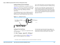
Installing and Removing Test Credit Buttons
E3995A test credit button(s) are installed as shown in
Figure 1-11. One 50k test credit button is included with
the PPU system. It is packaged in a 3-inch by 1.5-inch
box inside a plastic bag containing installation
instructions.
Test credit buttons may be inserted while the system is
running. To insert a button, grasp it with the flange or
labeled side up. Push the button firmly into one of the
Figure 1-11
ports of the button holder. Save the packaging material
until you are certain that the button is working correctly.
To remove a test credit button, grasp the button by its
flange and pull it straight out of the button holder. To
remove the button holder cable from the button adapter,
deflect one of the retaining latches with your fingernail,
a pen, or similar instrument. The button connector will
pop up for removal.
Installing PPU buttons
Dual Buttons Holder
with cable
PPU Buttons
PPU1HH.WPG
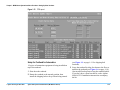
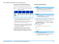
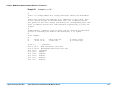
Verifying the Test Credit Buttons
From a 3070service logon, run a report that tests the
test credit buttons:
Verify that the button label and the button balance are
correct for the number of buttons installed.1 Buttons are
identified by the button label number on the button.
Click Start > Programs > Agilent 3070 > PPU Report?
A report similar to the one shown in Figure 1-12 on
page 1-30 will be displayed in a new window.
1 The E3994A 10k Test Credit Button may also be used and would indicate 10,000 credits.
© Agilent Technologies 2001–2003
Agilent 3070 System Installation Manual (MS Windows Version)
1-29
Chapter 1: MS Windows System Installation Procedure: Setting-Up Other Hardware
Figure 1-12
PPU report
Setup the Testhead for Automation
If a piece of automation equipment is being installed on
top of the testhead:
1 Shut down the testhead.
2 Rotate the testhead to the normal position, then
install the shipping bolts to keep it from being rotated
© Agilent Technologies 2001–2003
Agilent 3070 System Installation Manual (MS Windows Version)
(see Figure 1-1 on page 1-11 for shipping bolt
locations).
3 Screw the testhead leveling feet down to the floor to
stabilize the testhead (see Figure 1-6 on page 1-18).
Also install floor brackets to keep the testhead stable.
If you don’t have a floor bracket kit, order Agilent
44990-63221. Installation instructions accompany
the kit.
1-30
Chapter 1: MS Windows System Installation Procedure: Setting-Up Other Hardware
4 Use a 5-millimeter hex key wrench to remove the
safety shroud from around the testhead’s pin field.
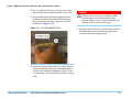
5 After installing the automation equipment on the
testhead, reach under the testhead and disconnect
the plug from the Auxiliary connector (J3) on the
System Card (Figure 1-13).
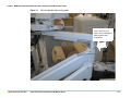
Figure 1-13
Connecting the EMO cable
WARNING
NOT operate the system without an EMO
✸ DO
switch properly wired and accessible to the
operator. Failure to provide EMO capability may
result in death or serious bodily injury.
7 Boot the testhead. When the testhead is booted, press
the EMO switch on the automation equipment to
verify that it is functioning properly.
6 Remove the jumper from terminals 11 and 12 on the
plug and connect the Emergency Shutdown (EMO)
switch on the automation equipment to pins 11 and
12 on the plug. Then reinstall the plug on the System
Card.
© Agilent Technologies 2001–2003
Agilent 3070 System Installation Manual (MS Windows Version)
1-31
Chapter 1: MS Windows System Installation Procedure: Setting-Up Other Hardware
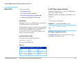
Figure 1-14
ASRU card connections (rear view)
)
Supplies 1-4
Supplies 5-6
Functional Ports
03066-66532 ASRU Card
White band
Red band
Install AccessPlus Cables
Complete this section only if the system includes the
AccessPlus option.
• Route the AccessPlus cables through the slots in the
module doors, shown in Figure 1-8 on page 1-25.
© Agilent Technologies 2001–2003
Agilent 3070 System Installation Manual (MS Windows Version)
1-32
Chapter 1: MS Windows System Installation Procedure: Enabling the Testhead
Enabling the
Testhead
This section contains:
■
Boot the Testhead, 1-33
■
Troubleshooting Testhead Boot, 1-33
■
Check the System Config File, 1-34
Boot the Testhead
NOTE
The first time the testhead is booted, there will be
several Warning - Standard calibration tables not
loaded for Module X Slot X messages.
These warning messages are normal; they are
generated because there are no valid AutoAdjust
tables in the
$AGILENT3070_ROOT/diagnostics/th1/cal_B
subdirectory.
These warning messages should not be seen after
the AutoAdjust process is completed later.
3 Start DGN if it does not start automatically:
a Open a Korn shell window:
One way is to click Start > Programs > Agilent
3070 > Korn Shell.
b At the Korn Shell window prompt enter:
dgn
4 In the DGN window, boot the testhead using the
Testhead Functs and Testhead Power On function
keys.
Troubleshooting Testhead Boot
If the testhead will not boot, watch the LEDs on the
ControlXT/XTP Card for proper sequencing, and watch
the monitor screen during the approximately
two-minute power-up process for clues.
See Table 1-4 on page 1-34 to identify the control card
status LEDs in the following LED sequencing
discussion.
1 Apply PDU power to the testhead:
Switch on the green rocker switch on the PDU.
2 Boot the controller (if not already booted), then log
on as service3070 (default password is service).
© Agilent Technologies 2001–2003
Agilent 3070 System Installation Manual (MS Windows Version)
1-33
Chapter 1: MS Windows System Installation Procedure: Enabling the Testhead
Check the System Config File
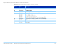
Description of ControlXT/XTP LED Sequencing
1 After about 2 minutes LED activity will begin.
Table 1-4
LED
Ref Des
Color
R=Red
G=Green
ControlXT/XTP Card status LEDs (as viewed
from the card edge)
6
7
4
5
2
3
0
1
■
■
■
■
■
■
■
■
R G
R G
R G
R G
2 Some various quick green-LED activity will be seen,
then LED7 will flash for about 30 seconds.
3 More quick LED activity will occur including some
red LEDs on for only about 2 seconds.
4 The sequence concludes successfully with green
LEDs 5 and 7 continuously toggling opposite each
other (heartbeat condition).
No red LEDs should remain on. If the testhead
encounters boot errors, verify the bootptab file
contains the unique hardware address of the control
card. See the Agilent 3070 / 79000 Repair Manual.
NOTE
Non-matching config files can result from the
controller being shipped separate from the
testhead, or if testhead cards have been moved.
NOTE
The Actual Config function key F4 polls the cards
in the testhead to identify their type.
1 Compare the system and standard config files to the
configuration printouts shipped with the system:
Open a Korn shell window: Click Start > Programs >
Agilent 3070 > Korn Shell.
2 At the prompt enter:
cd $AGILENT3070_ROOT/diagnostics/th1
then,
more config
NOTE
For more information about
$AGILENT3070_ROOT, see “The Root Directory
Environment Variable” in Chapter 2.
© Agilent Technologies 2001–2003
Agilent 3070 System Installation Manual (MS Windows Version)
1-34
Chapter 1: MS Windows System Installation Procedure: Enabling the Testhead
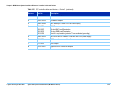
3 Do the two system config files match the system
configuration printout that was shipped with the
system?
■
If yes, continue to Verifying the Testhead on
page 1-39.
■
If no, continue with step 4.
4 Ask the customer's system administrator if there is a
plan for configuring the card locations.
5 Edit the system config files to match the actual card
locations. For more information, see “Editing Files”
in Chapter 2.
6 Compile the configuration files. For more
information, see “Compile the two Config Files” in
Chapter 2. .
NOTE
If the config files will not compile correctly, check
if the codewords are correct.
For more information, see “Verify Installed
Codewords” in Chapter 2.
7 Close the Korn Shell window.
© Agilent Technologies 2001–2003
Agilent 3070 System Installation Manual (MS Windows Version)
1-35
Chapter 1: MS Windows System Installation Procedure: Verifying the Vacuum Subsystem
Verifying the
Vacuum Subsystem
This section contains:
■
Introduction, 1-36
■
Install the Vacuum Manifold, 1-36
■
Connect the Compressed Air, 1-36
■
Check the Vacuum Actuation System, 1-36
■
Troubleshooting, 1-37
Introduction
The 327X (one-module) testhead has at least one
internal vacuum solenoid. The second internal solenoid
is optional.
It is the customer's responsibility to connect external
vacuum solenoid control wires to the System Card if
external solenoids are used.
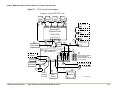
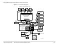
See Figure 1-15 on page 1-38 to reference internal
vacuum solenoids in a 4-module testhead.
Install the Vacuum Manifold
• Install the vacuum manifold on the vacuum ports
located toward the rear of the testhead,
• See Figure 1-8 on page 1-25 for the vacuum port
locations.
Connect the Compressed Air
• A male-quick-disconnect air fitting is installed on the
rear of the testhead to connect to the compressed air
supply,
• If the customer's compressed air hose has the opposite fitting to mate with the testhead fitting, install the
included female quick-disconnect fitting.
Check the Vacuum Actuation System
NOTE
See “Vacuum Control Specifics” in Chapter 2 for
more information.
1 If a vacuum source is connected and the solenoid(s)
are wired, turn the vacuum on and off and listen for
the sound of solenoids operating:
a Install and lock-down a fixture.
b Open a BT-BASIC window.
One way is to double-click the BT-BASIC desktop
icon.
c At the BT-BASIC window prompt, enter:
1) testhead is 1
2) vacuum well a is <m>
where <m> = a valid module vacuum port
(where the vacuum manifold or external
vacuum hoses are connected).
© Agilent Technologies 2001–2003
Agilent 3070 System Installation Manual (MS Windows Version)
1-36
Chapter 1: MS Windows System Installation Procedure: Verifying the Vacuum Subsystem
d At the prompt, alternately enter:
• faon
• faoff
Otherwise, use a voltmeter to verify that the 24-volt
dc can be switched to all terminal pairs of the
auxiliary connector (J3) on the System Card. See
Figure 1-15 on page 1-38 for the relay wiring block
diagram.
■
With the testhead powered-up, look at the system
config file:
$AGILENT3070_ROOT/diagnostics/th1/config
NOTE
For more information about
$AGILENT3070_ROOT, see “The Root Directory
Environment Variable” in Chapter 2. .
NOTE
Early 317x and 3070 systems used external
vacuum solenoids.
Troubleshooting
If the vacuum control will not work, check:
© Agilent Technologies 2001–2003
■
If the vacuum source is turned on.
■
If the compressed air supply is turned on.
■
If the 24 VDC is present on the Auxiliary port
when switched on.
■
If the solenoid is operating correctly.
■
How many solenoids are being used to control the
vacuum?
■
Which Auxiliary ports are being used to control
which solenoids?
■
If external solenoids are used, which solenoids
have hoses to which vacuum ports?
Agilent 3070 System Installation Manual (MS Windows Version)
NOTE
The vacuum well is normally defined in the
testplan.
The vacuum outlets are where the vacuum
connects to the test fixture on top of the testhead.
Agilent 317X and 327X testheads have two
vacuum ports – for the 327X testhead, ports 2 and
3 are reversed from the orientation shown in
Figure 1-15 on page 1-38.
• Verify that the relay <r> controls vacuum
<m> statement(s) agree(s) with the hardware:
• r = 1 for Aux 1.
• r = 2 for Aux 2.
• r = 3 for Aux 3.
• r = 4 for Aux 4.
• r = 5 for Aux 5.
• m = the module vacuum port(s) connected (can
be 0; 1; 2; 3; 0,1; 2,3; 0-3).
1-37
Chapter 1: MS Windows System Installation Procedure: Verifying the Vacuum Subsystem
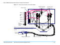
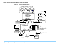
Figure 1-15
Internal vacuum solenoids in a four-module testhead
80-PSI Regulator
03066-67911
System Card
Relay 1 +_
1
Relay 2 +_
3
2
5
Relay 4 +
7
_
Relay 5 +
_
Remote
Shutdown
Jumper
Port1
Port3
Port0
4
Relay 3 +_
Vacuum Valve
E3770-67900
Port2
6
8
9
+
_
1
2
+
_
3
+
_
5
+
_
7
+
_
4
6
8
9
10
11
12
10
0ut
In
11
12
E9900-63200
4-Module Manifold
Air Lines
E9946A Vacuum components shown above the dotted line
Vacuum components below the dotted line are customer
supplied
Vacuum
Source
Pressure Gage
Manual Cut-off Valve
© Agilent Technologies 2001–2003
Agilent 3070 System Installation Manual (MS Windows Version)
2-inch Vacuum Hose
1-38
Chapter 1: MS Windows System Installation Procedure: Verifying the Testhead
Verifying the
Testhead
Run AutoAdjust All
CAUTION
the testhead to warm up for 30 minutes
✸Allow
before running AutoAdjust All.
If the testhead temperature is not allowed to
stabilize, diagnostic and testing failures may
appear later.
Run Full Diagnostics
NOTE
Compressed air must be attached to the system to
run full Diagnostics.
1 Place a pin verification fixture on the testhead, then
lock it down.
2 Change Manual Intervention to Yes (press Next Value).
1 Verify a service3070 logon.
2 Start Diagnostics if it does not start automatically:
a Click Start > Programs > Agilent 3070 > Korn
Shell.
b At the Korn Shell window prompt, enter:
dgn
3 From the Service Package - Level 1 menu, select
Config.
NOTE
Do not press Save Config as that will make the
Manual Intervention selection permanent.
3 Run Full Diagnostics.
4 Verify that there are no errors.
5 Logout of DGN.
4 Select DGN Config.
5 Press function key F6 in the AutoAdjust menu to run
AutoAdjust All.
6 Verify that there are no errors.
© Agilent Technologies 2001–2003
Agilent 3070 System Installation Manual (MS Windows Version)
1-39
Chapter 1: MS Windows System Installation Procedure: Completing the Installation
Completing the
Installation
Verify Strip Printer
Reinstall Covers
1 Open a BT-BASIC window.
If any pod or cradle covers are still off the system,
reinstall them now.
2 Enter: printer is “/dev/com/2”
3 Enter: print “strip printer test”
Do this a couple of times. The printer should print
“strip printer test.”
4 Enter: printer is *
5 Close the BT-BASIC window.
System Printer / Plotter
The customer's system administrator or LAN manager
will provide the device’s name, IP address, and driver.
Make System Recovery and Backup Tapes
A recovery tape allows you to boot the controller after a
catastrophic fault, such as when you can no longer boot
from disk.
To make a backup or recovery tape, see Administering
Agilent 3070 MS Windows Systems.
CAUTION
system recovery tape will overwrite all
✸ Using
existing data on system controller.
Stabilize the Testhead
Stabilize the testhead to keep it from moving around on
the floor:
Turn System Administration Over to the
Customer
• Use a hex-key wrench to screw the testhead's four
leveling feet down to the floor.
Inform the customer of the appropriate logins and
passwords for the system.
See Figure 1-6 on page 1-18 for the location of a
leveling foot.
NOTE
It may be necessary to remove the pod cover to
access the hex-slot of the leveling foot.
© Agilent Technologies 2001–2003
Agilent 3070 System Installation Manual (MS Windows Version)
Fill Out the System Support Log
Introduce the customer to the Agilent 3070 / 79000
System Support Log, 03066-90150.
1 Place your business card in Chapter 1, and suggest
that other Agilent representatives' cards belong there
too.
1-40
Chapter 1: MS Windows System Installation Procedure: Completing the Installation
2 Place the customer's Agilent 3070 software licenses
in Chapter 2.
■
Installing the system and completing full
Diagnostics – four hours.
3 Fill out the Installation and Configuration Records to
reflect the system.
Contact EMTD at 1.800.447.TEST to bill charges above
and beyond this scope.
Maintenance Records
Do not include repair time on the installation repair
order. Instead, complete a separate repair order for any
warranty repair associated with the installation.
If a problem was fixed that warrants a Maintenance
Record, fill one out now.
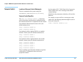
About ScanWorks
If the testhead is equipped with ScanWorks
boundary-scan, the system config file
($AGILENT3070_ROOT/diagnostics/th1/config)
and standard config file ($AGILENT3070_ROOT/
standard/config) must be edited to use the
ScanWorks hardware. This is the customer’s
responsibility. See the Syntax Reference User’s manual
for information on the ports... statement. You should
have code similar to this in your config files:
performance port
port 2 100 pin bsi 1
end performance port
Installation Billing Information
Up to eight hours may be charged to Agilent's
Electronics Manufacturing Test Division (EMTD/0900)
for performing the scope of the system installation that
includes:
© Agilent Technologies 2001–2003
■
Initial site preparation – two hours.
■
Verifying the site preparation – two hours.
Agilent 3070 System Installation Manual (MS Windows Version)
1-41
Chapter 1: MS Windows System Installation Procedure: In Case of Difficulty
In Case of Difficulty
Shipping Damage or Incorrect Shipment
Additional Resources
Contact your local Agilent Sales office.
If you need phone support, contact Agilent's Customer
Support Center. Go to the Agilent Automated Test
Equipment Contacts website and select your country:
Network, System Administration, or Test Server
Help
■
Review Chapter 2 in the System Installation
Manual (MS Windows Version) for more
information.
■
See Administrating Agilent 3070 MS Windows
Systems. This manual is also available in
electronic format as part of the User
documentation shipped on the controller’s hard
drive.
www.agilent.com/see/contact_info
Optional Agilent Performance Port Actuator
Control System (ACS)
See Agilent Performance Port in the 3070 Service
Documentation.
Vacuum Subsystem
See “Air Subsystems” troubleshooting in the online
service documentation.
© Agilent Technologies 2001–2003
Agilent 3070 System Installation Manual (MS Windows Version)
1-42
2
MS Windows System Installation Reference
E9970-90001 Rev. J 10/2003
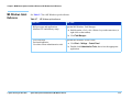
In this Chapter...
© Agilent Technologies 2001–2003
■
Logging-On as service3070, 2-2
■
Troubleshooting LAN Port Connections, 2-61
■
The Root Directory Environment Variable, 2-3
■
Installing Drivers and Configuring LAN Ports, 2-62
■
Directory Descriptions, 2-7
■
Editing Files, 2-8
■
MS Windows Quick Reference, 2-15
■
BT-BASIC Quick Reference, 2-16
■
Korn Shell Quick Reference, 2-17
■
vi and vi Editor Quick Reference, 2-20
■
Codewords & Software License Keys, 2-24
■
System Config File Specifics, 2-26
■
Standard Config File Specifics, 2-29
■
Compiling the System and Standard Config Files, 2-35
■
The bootptab File, 2-36
■
The hosts File, 2-38
■
Device Files, 2-40
■
Vacuum Control, 2-41
■
Rotating the Testhead, 2-42
■
Testhead Cards, 2-43
■
DUT Power Supplies, 2-45
■
Controller Cables and Devices, 2-49
■
Private LAN and Serial Port MUX, 2-59
Agilent 3070 System Installation Manual (MS Windows Version)
Referenced Manuals
The following manuals are referenced within this
chapter:
■
Administering Agilent 3070 MS Windows Systems,
■
Agilent 3070 / 79000 Family Site Preparation
Manual E9900-90045,
■
3070 / 79000 Family Board Test Systems Repair
Manual,
■
Agilent 3070 Family Users' Manual.
Introduction
The information in this chapter may be helpful when
installing an Agilent 3070 system that has a MS
Windows controller.
2-1
Chapter 2: MS Windows System Installation Reference: Logging-On as service3070
Logging-On as
service3070
The service3070 logon allows system configuration
and testing.
Display the Logon Status from a Current Login
1 Press the <Ctrl><Alt><Delete> keyboard keys at the
same time.
Logon as service3070 to Complete the
Installation
If it should be necessary to change the logon:
1 Press together <CTRL> <Alt> <Delete>.
2 Click Log Off.
Wait for the log off, then follow the on-screen
instructions to log back on.
3 Enter the logon information:
© Agilent Technologies 2001–2003
■
Logon Name = service3070
■
Default Password = service
Agilent 3070 System Installation Manual (MS Windows Version)
2-2
Chapter 2: MS Windows System Installation Reference: The Root Directory Environment Variable
The Root Directory
Environment
Variable
This section contains:
■
Introduction, 2-3
■
Determine the Value of the Root Directory
Environment Variable, 2-3
■
Use of the Root Directory Environment Variable in
a BT-BASIC Window, 2-4
■
Use of the Root Directory Environment Variable in
a Korn Shell Window, 2-5
■
Use of the Root Directory Environment Variable in
a DOS Command Prompt Window, 2-6
Determine the Value of the Root Directory
Environment Variable
1 Open a Korn shell window:
■
Double-click the desktop Korn Shell icon OR
■
Click Start > Programs > Agilent 3070 > Korn
Shell.
2 At the prompt, enter:
echo $AGILENT3070_ROOT
Introduction
The string returned is typically:
C:/Agilent3070
3070 systems now establish a root directory
environment variable.
Beginning with software revision 3070 04.00pa, an
environment variable is used to allow 3070 board files
to be easily transferred between 3070 systems running
either MS Windows or UNIX.
The environment variable is named
$AGILENT3070_ROOT. It replaces the root directory path
(upper path names) on both operating systems.
The directories, /var/hp3070 and /opt/hp3070, are
replaced by $AGILENT3070_ROOT on all MS Windows
systems.
The root directory environment variable default is set to
C:/Agilent3070.
© Agilent Technologies 2001–2003
Agilent 3070 System Installation Manual (MS Windows Version)
2-3
Chapter 2: MS Windows System Installation Reference: The Root Directory Environment Variable
Use of the Root Directory Environment Variable
in a BT-BASIC Window
Table 2-1 illustrates new path equivalents using the
system config file in a BT-BASIC window.
NOTE
BT-BASIC usage is the same in both UNIX and
MS Windows.
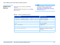
Table 2-1
Absolute & Environment Variable file path usage in BT-BASIC
Absolute Addressing at 3070 Software Release
3070 04.00pa
New Absolute addressing at 3070 Software
Release 3070 05.00p or later
Environment Variable Addressing at
3070 Software Release 3070 04.00pa or later
msi "D:/Agilent3070/diagnostics/th1"
msi "C:/Agilent3070/diagnostics/th1"
msi btgetenv$ ("AGILENT3070_ROOT") &
"/diagnostics/th1"
get "D:/Agilent3070/diagnostics/th1/
config"
get "C:/Agilent3070/diagnostics/th1/
config"
get btgetenv$ ("AGILENT3070_ROOT") &
"/diagnostics/th1/config"
NOTE
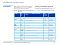
At software revision 3070 05.00p, the Agilent3070 directory was moved from D:/Agilent3070/ to C:/Agilent3070/
btgetenv$ ("AGILENT3070_ROOT") is only required for BT-BASIC commands which are referenced to the root.
If the BT-BASIC command msi btgetenv$ ("AGILENT3070_ROOT") & <command> is used prior to the next BT-BASIC command (for example
compile or faon), use of the environment variable to define the root path is unnecessary. BT-BASIC commands which normally contain paths (msi,
load, copy, save, get, store, unlink, rcall) for example, will require:
btgetenv$ ("AGILENT3070_ROOT") & <rest of path>
© Agilent Technologies 2001–2003
Agilent 3070 System Installation Manual (MS Windows Version)
2-4
Chapter 2: MS Windows System Installation Reference: The Root Directory Environment Variable
Use of the Root Directory Environment Variable
in a Korn Shell Window
In a Korn shell window, follow the UNIX syntax:
■
Use $<variable> (instead of %<variable>%).
■
Use the correct case.
■
Use / (forward slash) instead of \ (backslash).
Table 2-2 illustrates new path usage when working in a
Korn shell window.
Table 2-2
Absolute & Environment Variable file path usage in a korn shell window
Absolute Addressing at 3070 Software
Release 3070 04.00pa
New Absolute addressing at 3070
Software Release 3070 05.00p or later
Environment Variable Addressing at
3070 Software Release 3070 04.00pa or later
D:/Agilent3070/diagnostics/th1
C:/Agilent3070/diagnostics/th1
$AGILENT3070_ROOT/diagnostics/th1
/opt/hp3070/help/C/SERVICE
/opt/hp3070/help/C/SERVICE
$AGILENT3070_ROOT/Documentation/SERVICE
© Agilent Technologies 2001–2003
Agilent 3070 System Installation Manual (MS Windows Version)
2-5
Chapter 2: MS Windows System Installation Reference: The Root Directory Environment Variable
Use of the Root Directory Environment Variable
in a DOS Command Prompt Window
In a MS-DOS Command Prompt window:
■
Use %<variable>% (instead of $<variable>).
■
Use \ (backslash) instead of / (forward slash).
Table 2-3 on page 2-6 illustrates new path usage using
the dev directory as an example when working in a
MS-DOS Command Prompt window.
Table 2-3
Absolute & Environment Variable file path usage at a MS-DOS Command Prompt
Absolute Addressing at 3070 Software Release
3070 04.00pa
New Absolute addressing at 3070
Software Release 3070 05.00p or later
Environment Variable Addressing at
3070 Software Release 3070 04.00pa or later
D:\Agilent3070\dev
C:\Agilent3070\dev
%AGILENT3070_ROOT%\dev
© Agilent Technologies 2001–2003
Agilent 3070 System Installation Manual (MS Windows Version)
2-6
Chapter 2: MS Windows System Installation Reference: Directory Descriptions
Directory
Descriptions
Table 2-4 lists descriptions of some 3070 MS Windows
system directories.
Table 2-4
© Agilent Technologies 2001–2003
Descriptions of various 3070 MS Windows system directories
$AGILENT3070_ROOT/
The directory where the vast majority of the 3070 system software resides.
$AGILENT3070_ROOT/autofile
The directory that contains all the autofiles for the system.
$AGILENT3070_ROOT/bin
The directory that contains most of the executable programs for the system.
$AGILENT3070_ROOT/boards
The directory that should contain customer board directories.
$AGILENT3070_ROOT/contrib
The directory where user-contributed software that may be of use to 3070
customers is redistributed by Agilent.
$AGILENT3070_ROOT/dev
A directory that contains pseudo device files for use by the 3070 software.
$AGILENT3070_ROOT/diagnostics
A directory that contains testhead configuration and diagnostic information /
programs.
$AGILENT3070_ROOT/etc
A directory that contains miscellaneous files.
$AGILENT3070_ROOT/help
A directory that contains help information.
$AGILENT3070_ROOT/home
The directory that contains the MS Windows user's home directories.
$AGILENT3070_ROOT/lib
The directory that contains digital libraries and other executables.
$AGILENT3070_ROOT/library
The directory that contains device libraries provided for board development.
$AGILENT3070_ROOT/qm
The directory to which statistics are logged.
$AGILENT3070_ROOT/standard
A directory that contains templates used throughout the system.
$AGILENT3070_ROOT/tmp
A directory that is used by the 3070 software for storing temporary files /
logs.
$AGILENT3070_ROOT/util
A directory that is used for storing a few utility files.
Agilent 3070 System Installation Manual (MS Windows Version)
2-7
Chapter 2: MS Windows System Installation Reference: Editing Files
Editing Files
This section contains:
■
Front-Slashes versus Back-Slashes in Command
Lines Containing File Paths, 2-8
■
Use BT-BASIC, 2-8
■
How to Edit the System Config File to Match the
Testhead Configuration, 2-9
■
How to Resolve the Standard Config File from the
System Config File, 2-10
Front-Slashes versus Back-Slashes in Command
Lines Containing File Paths
A general rule for commands using a path to a directory
or file is to use a forward-slash (/) for commands tied to
a 3070 application, and use a back-slash (\) for operating
system-related commands.
■
Use BT-BASIC
BT-BASIC is the designated file-editing tool. Unless
otherwise specified, editing described in this chapter is
performed using BT-BASIC.
Korn shell, vi, and viw editors can also be used to edit
files.
Reference information for all these tools:
■
BT-BASIC Quick Reference on page 2-16.
■
Korn Shell Quick Reference on page 2-17.
■
vi and vi Editor Quick Reference on page 2-20.
If a command line containing a file path fails to execute,
it may be because the slash used is of the wrong type.
NOTE
BT-BASIC cannot be accessed when logged in as
administrator.
Reversing the slash(es) may resolve the issue.
This is because:
■
■
© Agilent Technologies 2001–2003
Many Korn shell commands are used in the MS
Windows environment, and require front-slashes
(/) in command lines containing file paths.
In MS Windows, when opening a file from the
Start > Run... menu, both front-slashes (/) and
back-slashes (\) are recognized.
Agilent 3070 System Installation Manual (MS Windows Version)
A command may be performed in or with some
relationship to the MS-DOS environment, which
can require back-slashes in command lines
containing file paths.
Open BT-BASIC
■
Double-click the desktop BT-BASIC icon OR
Click Start > Programs > Agilent 3070 > BT-BASIC.
BT-BASIC will open with the cursor on the
command line.
2-8
Chapter 2: MS Windows System Installation Reference: Editing Files
2 Enter:
Open a File in BT-BASIC
• From the command line, enter:
re-save
get btgetenv$ ("AGILENT3070_ROOT") &
"<path to the file>"
For more information about this command, see Use
of the Root Directory Environment Variable in a
BT-BASIC Window on page 2-4.
Exit BT-BASIC
1 Press F1 on the keyboard, if necessary, to toggle to
the command line.
2 Enter:
exit
Edit in BT-BASIC
• Press F1 on the keyboard, if necessary, to toggle to
the workspace.
To move the cursor, use the keyboard arrow keys,
and the Insert Char, and Delete Char keys.
How to Edit the System Config File to Match the
Testhead Configuration
If the testhead configuration has changed, the system
config file MUST be updated to reflect the change.
Table 2-5 on page 2-9 describes the process.
Save in BT_BASIC
1 Press F1 on the keyboard, if necessary, to toggle to
the command line.
Table 2-5
Edit the system config file to match the testhead configuration
Task
Step
1 Open the system config file
in a BT-BASIC window.
a Open a BT-BASIC window by double-clicking the desktop icon.
b From the BT-BASIC command line, enter:
get btgetenv$ ("AGILENT3070_ROOT") & "/diagnostics/th1/config"
2 Arrange or modify
statements to reflect the
actual testhead
configuration.
© Agilent Technologies 2001–2003
Do this as required.
See Table 2-8 on page 2-16 for commonly used BT-BASIC commands.
Agilent 3070 System Installation Manual (MS Windows Version)
2-9
Chapter 2: MS Windows System Installation Reference: Editing Files
Table 2-5
Edit the system config file to match the testhead configuration
Task
Step
3 Save and exit the system
config file.
• Enter:
1) re-save
2) exit
4 Compile the system config
file.
For instructions, see Compiling the System and Standard Config Files on
page 2-35.
How to Resolve the Standard Config File from the
System Config File
If the system config file has changed, it is good practice
to edit the standard config file to reflect the changes as a
service to the board test development personnel.
Figure 2-1 on page 2-14 illustrates the concept.
The desired end result is to copy the cards ..., serial
ports ..., supplies ... and ports ... statements
from the system config file to the standard config file.
No changes to the system config file are made.
See Table 2-6 to resolve the standard config file from
the system config file.
Table 2-6
Resolve the standard config file from the system config file
Task
Step
1 Make a backup copy of the
standard config file:
a Open a BT-BASIC window by double-clicking the desktop icon.
b At the prompt, enter:
msi btgetenv$ ("AGILENT3070_ROOT") & "/standard"
c copy config over config.temp
2 Open the standard config
file:
© Agilent Technologies 2001–2003
a Enter:
get btgetenv$ ("AGILENT3070_ROOT") & "/standard/config"
Agilent 3070 System Installation Manual (MS Windows Version)
2-10
Chapter 2: MS Windows System Installation Reference: Editing Files
Table 2-6
Resolve the standard config file from the system config file (continued)
Task
Step
3 Open the system config file
in a new BT-BASIC window:
• At the new BT-BASIC window command line, enter:
get btgetenv$ ("AGILENT3070_ROOT") & "/diagnostics/th1/config"
4 Arrange the two BT-BASIC
windows so that each can be
readily accessed.
5 Copy the appropriate
statements from the system
config file to the clipboard
buffer:
In the BT-BASIC window containing the system config file:
a Press F1 on the keyboard to enter the workspace.
b Locate the module <number> that contains un-commented
cards 1 ... statements using the arrow keys or the Prev and Next keys.
c Scroll the text up until the end module statement is visible.
d Click and drag with the mouse to highlight the text including the ports ...
statement
The highlighted text is now copied in the clipboard buffer.
NOTE
Do not include probe, debug port, bank, or end bank statements.
These statements are not valid in the standard config file.
© Agilent Technologies 2001–2003
Agilent 3070 System Installation Manual (MS Windows Version)
2-11
Chapter 2: MS Windows System Installation Reference: Editing Files
Table 2-6
Resolve the standard config file from the system config file (continued)
Task
6 Paste the copied text in the
standard config file:
Step
CAUTION
✸Do not delete the
! Specify instrument ...
through
statements.
! connect ...
a Activate the window containing the standard config file by clicking on the
window border.
b Press F1 on the keyboard to enter the workspace.
c Move the cursor immediately below the module <number> statement that
corresponds to the module <number> statement copied in the previous task.
■
Take care not to overwrite other lines.
d Click the right mouse button.
The text from the buffer will be inserted into the standard config file.
7 Verify that each
un-commented module
<number> and end module
statement in the system
config file is un-commented
in the standard config file.
8 Save , then exit the standard
config file:
a In the window containing the standard config file, press F1 to return to the
command line.
b Enter:
1) re-save
2) exit
© Agilent Technologies 2001–2003
Agilent 3070 System Installation Manual (MS Windows Version)
2-12
Chapter 2: MS Windows System Installation Reference: Editing Files
Table 2-6
Resolve the standard config file from the system config file (continued)
Task
Step
9 Exit the system config file
without saving it:
a In the window containing the system config file, press F1 to return to the
command line.
b Enter:
exit
10 Compile the standard config
file.
© Agilent Technologies 2001–2003
Instructions are given in Compiling the System and Standard Config Files on
page 2-35.
Agilent 3070 System Installation Manual (MS Windows Version)
2-13
Chapter 2: MS Windows System Installation Reference: Editing Files
Figure 2-1
Copying configuration information
$AGILENT3070_ROOT/standard/config
BT-BASIC
Status: xxx lines in workspace
configuration xxxx
! CONFIGURATION FOR DEVELOPING BOARD TESTS
!
target . . .
enable . . .
module . .
BT-BASIC
Status: xxx lines in workspace
! Specify instrument
end module
command
configuration xxxx
! relay 1 controls vacuum . . .
bank . .
module . .
cards 1 . . .
ports . . ., . . .
end module
module . .
cards 1 asru . . .
ports . . ., . . .
command
BASIC
$AGILENT3070_ROOT/diagnostics/th1/config
© Agilent Technologies 2001–2003
Agilent 3070 System Installation Manual (MS Windows Version)
2-14
Chapter 2: MS Windows System Installation Reference: MS Windows Quick Reference
MS Windows Quick
Reference
See Table 2-7 for a MS Windows quick-reference.
Table 2-7
MS Windows quick-reference
To Do This...
Enter This...
• Kill processes and applications
• Monitor CPU and memory usage
Open the MS Windows Task Manager:
a Hold down the <Ctrl><Alt><Delete> keys at the same time (or
right-click on the toolbar).
b Click Task Manager...
• View error logs
• Perform diagnostics
• Use other various administrative tools
Open the MS Windows Event Viewer:
a Click Start > Settings > Control Panel.
b Double-click Administrative Tools, then select the appropriate
application.
© Agilent Technologies 2001–2003
Agilent 3070 System Installation Manual (MS Windows Version)
2-15
Chapter 2: MS Windows System Installation Reference: BT-BASIC Quick Reference
NOTE
BT-BASIC Quick
Reference
Table 2-8 lists some commonly used BT-BASIC
statements.
Additional BT-BASIC information is given in Editing
Files on page 2-8.
Table 2-8
© Agilent Technologies 2001–2003
If uncertain whether to use front-slashes or
back-slashes, see Front-Slashes versus
Back-Slashes in Command Lines Containing
File Paths on page 2-8.
Commonly used BT-BASIC statements
BT-BASIC Statement
Statement Function
msi btgetenv$ ("AGILENT3070_ROOT") & "<path to the file>"
Change to file location
get btgetenv$ ("AGILENT3070_ROOT") & "<path to the file>"
Retrieve an existing file
save "<filename>"
Create a new file
re-save
Save an existing file
compile "<filename>"
Compile a file
compile "<filename>";testhead
Compile a testhead file
findn "<string expression>"
Find the next occurrence of a string
expression
exit
Quit BT-BASIC
Agilent 3070 System Installation Manual (MS Windows Version)
2-16
Chapter 2: MS Windows System Installation Reference: Korn Shell Quick Reference
NOTE
Korn Shell Quick
Reference
Although the operating system is MS Windows, a
number of 3070 UNIX commands are valid in the Korn
shell.
See Table 2-9 for a Korn shell quick reference.
Keyboard keys are in { }.
If uncertain whether to use front-slashes or
back-slashes, see Front-Slashes versus
Back-Slashes in Command Lines Containing
File Paths on page 2-8.
For complete information about a command, at a Korn
shell window prompt, enter:
man <command_name>
Table 2-9
Korn shell quick reference
Working with Directories
To Do This...
Enter This...
Show current working directory
pwd
Change directory
cd
Change to home directory
cd
Create a directory
mkdir
<directoryname>
Remove an (empty) directory
rmdir
<directoryname>
Display permissions for a directory
ls -ld
<pathname>
<directoryname>
Working with Files
© Agilent Technologies 2001–2003
To Do This...
Enter This...
List files and directories in current directory
ls
List all files or directories, including hidden ("dot") files
ls -a
List files, and show directories with / and executables with *
ls -f
Agilent 3070 System Installation Manual (MS Windows Version)
2-17
Chapter 2: MS Windows System Installation Reference: Korn Shell Quick Reference
Table 2-9
Korn shell quick reference (continued)
Display permissions for a file
ls -l
Create or edit a file
vi
Display file contents
more
Copy a file with permissions and owners
cp -p
Move a file to a new filename
mv
Append file1 onto the end of file2
cat
Remove a file
rm
<filename>
<filename> or viw <filename>
<filename> (q to quit) (v to vi)
<file1> <file2>
<old_file> <new_file>
<file1> >> <file2>
<filename>
Finding and Organizing
To Do This...
Enter This...
Find file(s) beginning with x in the current and sub-directories
find . -name 'x*' -print
Find all occurrences of word in all files in the current directory
grep word *
Display date and time
date
Display manual page for <command name>
man
Find name of current host system
hostname
Find current system information
uname -a
Find environment information, including PATH
env
<commandname>
System Operations
© Agilent Technologies 2001–2003
To Do This...
Enter This...
Clear screen
clear
Exit / close Korn shell window
exit
Agilent 3070 System Installation Manual (MS Windows Version)
2-18
Chapter 2: MS Windows System Installation Reference: Korn Shell Quick Reference
Table 2-9
Korn shell quick reference (continued)
Set Korn shell for vi
set -o vi
Edit the command line (in Korn shell set for vi)
{ESC}
Recall previous command line (in Korn shell set for vi)
{ESC}k
Execute previous command line (in Korn shell set for vi)
{Return}
List current process status and PID's
ps -ef
Redirect input from a file to a command
command < infile
Connect two processes with a "pipe"
command1 | command2
(use vi commands)
(back) or j (forward)
(when line is displayed)
Network Operations
© Agilent Technologies 2001–2003
To Do This...
Enter This...
Invoke FTP and connect to remote host
ftp
Set transfer mode to ASCII
ascii
Set transfer mode to binary
bin
Copy a file using ftp from remote_hostname
get
<remote_file>
Copy a file using ftp from the local current directory to current
directory on the remote_hostname
put
<local_file>
Exit FTP
bye
Agilent 3070 System Installation Manual (MS Windows Version)
<remote_hostname>
2-19
Chapter 2: MS Windows System Installation Reference: vi and vi Editor Quick Reference
NOTE
vi and vi Editor
Quick Reference
See Table 2-10 for a vi and viw editor quick reference.
Keyboard keys are in { }.
If uncertain whether to use front-slashes or
back-slashes, see Front-Slashes versus
Back-Slashes in Command Lines Containing
File Paths on page 2-8.
Table 2-10 vi and viw editor quick reference
Getting Started with vi
To Do This...
Enter This in Command Mode...
Create or edit a file in a Korn shell window
vi
Create or edit a file in a vi window
viw
Make sure you're in command mode
{ESC}
Show if you are in command or insert mode
:set showmode
Find out what file you are in
{CTRL}g
<filename>
<filename>
Moving Within a File
© Agilent Technologies 2001–2003
To Do This...
Enter This in Command Mode...
Move the cursor left or right
h
or l or arrow keys
Move the cursor up or down
k
or j or arrow keys
Cursor to end of line
$
Cursor to beginning of line
0
Cursor to end of file
G
Agilent 3070 System Installation Manual (MS Windows Version)
(Zero) or ^
2-20
Chapter 2: MS Windows System Installation Reference: vi and vi Editor Quick Reference
Table 2-10 vi and viw editor quick reference (continued)
Cursor to line <n>
<n>G
Inserting Text
To Do This...
Enter This in Command Mode...
Insert text at the cursor position
i
Insert a new line after the current line
O (capital)
Insert (Append) text after the cursor position
a
Backspace to overwrite previous character (in Insert Mode)
{CTRL}h
Replace single character
r
Replace until {ESC} is pressed
R
or {Backspace}
<character>
Deleting Text
To Do This...
Enter This in Command Mode...
Delete characters at cursor
x
Delete word (cursor at beginning of word)
dw
Delete the entire line at the cursor position
dd
Delete from cursor to end of the current line
D
Delete from cursor to end of the file
dG
Moving Text
© Agilent Technologies 2001–2003
To Do This...
Enter This in Command Mode...
Join lines of text
J
Agilent 3070 System Installation Manual (MS Windows Version)
2-21
Chapter 2: MS Windows System Installation Reference: vi and vi Editor Quick Reference
Table 2-10 vi and viw editor quick reference (continued)
Copy a line into a buffer
yy
Put copied or deleted text line from buffer after cursor line
p
Read in another file after cursor line
:r
<filename>
Searching Text
To Do This...
Enter This in Command Mode...
Search forward for <words>
/<words>
Search backward for <words>
?<words>
Repeat the previous search for words
n (next) or N (previous)
Saving and Printing Files
To Do This...
Enter This in Command Mode...
Save file in same filename
:w
Save file to a new filename
:w
Exit from file without saving changes
:q!
Overwrite another existing file with this file
:w!
Save and exit from the vi editor
:wq
<new_filename>
or wq!
Repairing Mistakes
© Agilent Technologies 2001–2003
To Do This...
Enter This in Command Mode...
Undo the previous action
u
Restore a line to its previous state
U
Restore ("put") last delete
p
Agilent 3070 System Installation Manual (MS Windows Version)
2-22
Chapter 2: MS Windows System Installation Reference: vi and vi Editor Quick Reference
Table 2-10 vi and viw editor quick reference (continued)
© Agilent Technologies 2001–2003
Restore current file to last saved text and disregard changes
:e!
Undo last edit
u
Recover a file after a system interruption (from the Korn shell)
vi -r
Agilent 3070 System Installation Manual (MS Windows Version)
(repeat to toggle)
<filename>
2-23
Chapter 2: MS Windows System Installation Reference: Codewords & Software License Keys
Codewords &
Software License
Keys
This section contains:
■
Introduction, 2-24
■
Installing Codewords & Software License Keys,
2-24
■
Verify Installed Codewords, 2-24
■
Compile the Two Config Files, 2-24
Introduction
Codewords & software license keys are pre-installed at
the factory and normally do not require adjustment.
The capabilities of a 3070 system are based on the
codewords and software licenses installed.
Codeword & software licenses are used by the system
config file compiler and allows confirmation that the
hardware and the supported software features are
compatible.
NOTE
Agilent will issue software license keys to replace
the current codeword scheme for new 3070
features starting with software release 05.20p. At
present, only new features will require the license
key.
© Agilent Technologies 2001–2003
Agilent 3070 System Installation Manual (MS Windows Version)
Installing Codewords & Software License Keys
Instructions for installing codewords are included with
the software license(s) and Entitlement Certificate(s).
Verify Installed Codewords
To verify the codewords & software license keys:
a Click Start > Programs > Command Prompt.
b At a command window prompt, enter:
codeword -l
(el, not one)
c If errors are returned, the board config will not
compile properly.
Compile the Two Config Files
CAUTION
codewords have changed in any way, it will
✸ Ifbethenecessary
to compile both the system and
standard config files. Instructions are given in
Compiling the System and Standard Config
Files on page 2-35.
2-24
Chapter 2: MS Windows System Installation Reference: Codewords & Software License Keys
CAUTION
entered codewords, blank lines or
✸Incorrectly
spaces before or after a codeword may cause
errors when compiling the config files. User and
Operator logins may not boot if the
$AGILENT3070_ROOT/lib/.enable file contains
invalid information. Codeword order does not
matter.
© Agilent Technologies 2001–2003
Agilent 3070 System Installation Manual (MS Windows Version)
2-25
Chapter 2: MS Windows System Installation Reference: System Config File Specifics
System Config File
Specifics
This section contains:
■
Introduction, 2-26
■
Location of the System Config File, 2-26
■
Edit the System Config File, 2-26
■
The "Official" and "Actual" System Config Files,
2-26
■
To Repair a Corrupt System Config File, 2-26
■
Descriptions of Some Statements in the System
Config File, 2-27
2 At a BT-BASIC window prompt, enter:
msi btgetenv$ ("AGILENT3070_ROOT") &
"/diagnostics/th1"
3 Enter:
get "config"
Introduction
The system config file must match the testhead card
configuration.
4 Edit the file to match the actual testhead card
configuration.
5 Enter:
re-save
6 Compile the changed system config file. See
Compiling the System and Standard Config Files
on page 2-35
The "Official" and "Actual" System Config Files
Edit the system config file if either the testhead cards or
locations of the testhead cards have changed.
The "official" system config file is the system config file
as when the system was shipped.
Location of the System Config File
It is contained on a printout shipped with the system,
and can be used as a model if it should be necessary to
customize the system config file.
The path to the system config file is:
Edit the System Config File
The "actual" system config file is the system config file
in use which reflects the actual cards and card locations
in the testhead.
1 Login as service3070 (default password is
service).
To Repair a Corrupt System Config File
$AGILENT3070_ROOT/diagnostics/th1/config
One of the sys.config.xxx templates can be copied
from the $AGILENT3070_ROOT/diagnostics directory
and edited to match the actual system configuration.
© Agilent Technologies 2001–2003
Agilent 3070 System Installation Manual (MS Windows Version)
2-26
Chapter 2: MS Windows System Installation Reference: System Config File Specifics
NOTE
Changes to the system config file should be
reflected in the standard config file. See Standard
Config File Specifics on page 2-29.
The line frequency Statement
In this statement, the unused frequency is commented.
For example, if the system power is connected to 60
hertz, 50 is commented.
NOTE
Descriptions of Some Statements in the System
Config File
"Commented" means that the comment character,
an exclamation mark (!), has been placed at the
beginning of a line.
The testhead name Statement
The testhead name statement in the system config file
identifies the block in the bootptab file that contains
hardware and IP addresses for the System Card and
ControlXT/XTP Cards.
See Vacuum Control on page 2-41.
The testhead name statement in the system config file
includes only the modules that are present; for a
four-module system it looks like:
These statements identify to the system which cards are
installed and where they are installed.
testhead name testhead1 module3 module2
module1 module0
The System Card is represented by testhead1
The ControlXT/XTP Card in each module is
represented by module<n>
Modules are mapped in the hosts file. Using this
information, specific hardware addresses can be
determined in the bootptab file.
© Agilent Technologies 2001–2003
Agilent 3070 System Installation Manual (MS Windows Version)
The relay Statement
The cards <keywords> Statements
See Table 2-15 on page 2-43 for available 3070 testhead
cards with diagnostics names, cards <keywords>
statements, pattern applications rates and part numbers.
The cards <keywords> statements can be delimited by
commas (,); a range can be separated by the word "to."
Valid examples are:
■
cards 2, 3, 4, 5 hybrid standard double
density
■
cards 2 to 5 hybrid standard double
density
■
cards 2, 4, 7 to 11 hybrid standard
double density
2-27
Chapter 2: MS Windows System Installation Reference: System Config File Specifics
The supplies <keywords> Statements
Numbering of the supplies in the supplies
statements is arbitrary.
<keywords>
The software will accept any mapping of supply
numbers to modules.
If the customer plans to share board test fixtures with
other systems, it is possible they may have modified the
default power supply setting.
If so, reconcile the supplies numbering with existing
systems.
© Agilent Technologies 2001–2003
Agilent 3070 System Installation Manual (MS Windows Version)
2-28
Chapter 2: MS Windows System Installation Reference: Standard Config File Specifics
Standard Config
File Specifics
This section contains:
■
Introduction, 2-29
■
The Board Config File, 2-29
■
Standard Config File Syntax Similarities to and
Differences from the System Config File, 2-29
■
Statements Allowed in the Standard, System, and
Board Config Files, 2-30
■
Statements Allowed in the System Config File, 2-30
■
Descriptions of Some Statements in the Standard
Config File, 2-30
The Board Config File
The board test developer can use the standard config file
as a template when developing a board config file.
The board config file is located in each board's
subdirectory, and is a copy or subset of the standard
config file.
The board config file can describe the resources in any
one system or system subset.
Standard Config File Syntax Similarities to and
Differences from the System Config File
Introduction
The cards <keywords> syntax is the same for the
system config file and the standard config file.
The standard config file should reflect all testhead
resources available to the board test developer.
However, some of the syntax for the standard config file
is different from that of the system config file.
As shipped, the standard config file:
■
Has the correct target <keywords> statement.
■
Includes commented enable <keywords>
statements for optional components.
Location of the Standard Config File
The path to the standard config file is:
$AGILENT3070_ROOT/standard/config
© Agilent Technologies 2001–2003
Agilent 3070 System Installation Manual (MS Windows Version)
2-29
Chapter 2: MS Windows System Installation Reference: Standard Config File Specifics
Statements Allowed in the Standard, System, and
Board Config Files
•
•
•
•
•
•
target
enable
module
end module
access ports
boards wired in
parallel
•
•
•
•
•
cards
supplies
ports
boards
connect
NOTE
statements allow programmers to name
and define the use of external ports.
Statements Allowed in the System Config File
•
•
•
•
testhead name
line frequency
board handler
relay <x> controls
vacuum <y>
•
•
•
•
bank
end bank
probe
debug port
NOTE
These statements are not allowed in either the
Standard or Board Config Files, but are allowed in
the System Config File.
connect
Usually these can remain as-shipped until the
customer decides how to use these ports.
Descriptions of Some Statements in the Standard
Config File
The target <keywords> Statements
A target <keywords> statement is needed in each
board config file.
See Table 2-11 for factory default target <keywords>
statements.
NOTE
The target <keywords> statement should be the
first un-commented statement in the file and must
exist before the cards <keywords> statements.
© Agilent Technologies 2001–2003
Agilent 3070 System Installation Manual (MS Windows Version)
2-30
Chapter 2: MS Windows System Installation Reference: Standard Config File Specifics
Table 2-11 Factory default target <keywords> statements
Pattern Application Rate (MP/s (mega
patterns-per-second))
target <keyword> Statement
2
target Agilent3070 value
6
target hp3073 standard
12
target hp3070 advanced
20
target high accuracy
See Table 2-12 for 3X72 process test system default
target <keywords> statements.
Table 2-12 3X72 process test system default target <keywords> statements
Product Description
target <keyword> Statement
Agilent 3172-U Unpowered Test (up to 2modules)
target unpowered
Agilent 3072-U Unpowered Test (up to 4 modules)
target unpowered
Agilent 3172-P Powered Test (up to 2 modules)
target unpowered
enable power testing
Agilent 3072-P Powered Test (up to 4 modules)
target unpowered
enable power testing
Agilent 3X72 Test Development System Software and
Licenses
© Agilent Technologies 2001–2003
Agilent 3070 System Installation Manual (MS Windows Version)
target unpowered
2-31
Chapter 2: MS Windows System Installation Reference: Standard Config File Specifics
The enable <keywords> Statements
These statements are used in combination with
codewords to selectively enable software features.
or optional software features as the board config file is
developed.
NOTE
Codewords must be installed to enable optional
software features. For more information, see
Codewords & Software License Keys on
page 2-24.
CAUTION
✸the
enable <keywords> statements should exist after
target <keywords> statements, and must be
outside of a module block.
The programmer will un-comment the correct enable
<keywords> statements which correspond to standard
Table 2-13 contains some enable <keywords>
statements in the standard config file.
Table 2-13 Some enable <keywords> statements in the standard config file
© Agilent Technologies 2001–2003
enable <keywords>
Functional Description:
advanced boundary scan
Enables you to test chains of boundary scan parts, such as testing the
interconnections without nailed access.
all high accuracy
resources
For double density, high accuracy HybridPlus Cards, this option enables channel
resources to be routed to pins that would otherwise be used for extended grounding
on XG-50 fixtures. Because the resource assignments change, this option cannot be
used with XG-50 fixtures.
combo test
Enables both in-circuit and functional test.
common delimiter
Enables interoperability between UNIX and MS Windows
connect check
Enables Agilent Connect Check.
dual well shared
wiring
Enables dual-well shared wiring.
Agilent 3070 System Installation Manual (MS Windows Version)
2-32
Chapter 2: MS Windows System Installation Reference: Standard Config File Specifics
Table 2-13 Some enable <keywords> statements in the standard config file
© Agilent Technologies 2001–2003
enable <keywords>
Functional Description:
drivethru
Enables the testing of digital devices through series resistors using Agilent TestJet
technology. You can use the Agilent Drive Thru Test in combination with the
Agilent Access Consultant to identify and selectively remove nonessential probing
locations.
express fixturing
Allows Agilent SimPlate Express or cassette fixtures for your board test. If this
option is not enabled, only an Agilent SimPlate Fixture can be used.
flash70
Enables flash memory programming mode.
flash isp
Enables flash isp software, which supports new data formats. Only supported with
ControlXTP cards.
incircuit test
Enables automatic in-circuit test generation for systems which do not have it.
magic
Enables Agilent MagicTest circuit analysis mode.
multiple board
versions
Enables Agilent Multiple Board Versions.
paneltest
Enables software that helps you develop tests for multiple-board panels on one
fixture.
pld isp
Enables native PLD programming on the 3070 and supports CPLD programming
with STAPL, SVF, Jam and JBC file types. Only supported with ControlXTP cards.
polarity check
Enables Agilent Polarity Check testing.
powered testing
Allows limited powered testing on an Agilent 3072 system (a maximum of two
HybridPlus Cards, one HybridPlus and one ChannelPlus Card, or one HybridPlus
and one AccessPlus Card per module).
silicon nails
Enables automatic generation of silicon nails ITL test files derived from library tests
and customized to the board topology on user selected devices.
Agilent 3070 System Installation Manual (MS Windows Version)
2-33
Chapter 2: MS Windows System Installation Reference: Standard Config File Specifics
Table 2-13 Some enable <keywords> statements in the standard config file
© Agilent Technologies 2001–2003
enable <keywords>
Functional Description:
testjet
Enables the TestJet testing technique on your board. This option is automatically
enabled on the Agilent 3072 system.
throughput multiplier
Allows testing up to four boards simultaneously (one per module), which increases
board throughput. It can only be used with the paneltest option.
Agilent 3070 System Installation Manual (MS Windows Version)
2-34
Chapter 2: MS Windows System Installation Reference: Compiling the System and Standard Config Files
Compiling the
System and
Standard Config
Files
For changes to the system config file and the standard
config file to be enabled, they must be compiled.
NOTE
If codewords have been modified in any way, both
the system and standard config files must be
compiled.
To compile the config files:
1 Login as service3070 (default password is
service)
2 Open BT-BASIC.
3 Compile the system config file. At the command line,
enter:
a msi btgetenv$ ("AGILENT3070_ROOT") &
"/diagnostics/th1"
b compile "config"; testhead
4 Compile the standard config file. At the command
line, enter:
a msi btgetenv$ ("AGILENT3070_ROOT") &
"/standard"
b compile "config"
5 When the config files have compiled without errors,
exit BT-BASIC.
© Agilent Technologies 2001–2003
Agilent 3070 System Installation Manual (MS Windows Version)
2-35
Chapter 2: MS Windows System Installation Reference: The bootptab File
The bootptab File
2 Make a backup copy. One example:
This section contains:
■
Hardware Addresses, 2-36
■
IP Addresses, 2-37
a Open Windows Explorer:
• For Windows NT, click Start > Programs >
Windows NT Explorer.
Hardware Addresses
Each System Card and Control Card has a unique
hardware address (HA).
When changing a System Card, remove the ROM(s)
from the pre-existing card and install it on the new card.
When changing a Control Card, update the bootptab
file to reflect the unique HA of the new card.
• For Windows 2000, click Start > Programs >
Accessories > Windows Explorer.
b Navigate to:
C:\WINNT\system32\drivers\etc
c Right-click on the bootptab file then select copy.
d Navigate to:
C:\Temp
CAUTION
made to the
file MUST be
✸Changes
done through the Bootp Server program.
bootptab
e Right-click and select paste.
An unchanged copy is now in C:\Temp
3 Open Bootp Server:
NOTE
The environment variable $SystemRoot is
usually set to c:\winnt\system32
Given below is a method to edit the bootptab file:
1 Login as service3070 (password is service).
a Click Start > Settings > Control Panel.
b Double-click BOOTP Server.
4 In the BOOTP Server properties window, click the
Clients tab.
5 If a ControlXT/XTP Card was removed, delete its
hardware address:
a Pull down the Hardware Address menu and
select the address of the card removed.
b Click Delete.
© Agilent Technologies 2001–2003
Agilent 3070 System Installation Manual (MS Windows Version)
2-36
Chapter 2: MS Windows System Installation Reference: The bootptab File
6 Add the HA of the ControlXT/XTP Card you are
installing:
a Click New.
b Enter the ControlXT/XTP Card HA. The
complete HA is typically 0060B0B2xxxx (xxxx =
the number on the card).
7 Configure the card’s IP address:
a In the Available options menu, select the following
three options one at a time and click >> to move
them to the Configured options menu:
• IP address >>
• Merit dump file >>
• Subnet mask >>
9 Restart the BOOTP Server:
a From Control Panel click Services.
b Double-click Weird Solutions BOOTP Server.
c Click Stop > Yes (wait) > Start (wait).
10 Close the Services and Control Panel windows.
This completes the procedure.
IP Addresses
The bootptab file, in conjunction with the hosts file,
manages IP addresses for the modules in the testhead.
See The hosts File on page 2-38 to view IP addresses
for the testhead modules.
b In the Configured options menu, select each option
and click Edit.
Enter:
• IP Address = 10.3.112.4 for module 0
10.3.112.5 for module 1
10.3.112.6 for module 2
10.3.112.7 for module 3
• Merit dump file = This is a comment; enter
the module number (e.g., module 2).
• Subnet mask = 255.255.255.0
8 In the BOOTP Server properties window, click Close.
© Agilent Technologies 2001–2003
Agilent 3070 System Installation Manual (MS Windows Version)
2-37
Chapter 2: MS Windows System Installation Reference: The hosts File
The hosts File
The path to the hosts file is:
■
$SystemRoot/system32/drivers/etc/hosts
NOTE
$SystemRoot
is an environment variable that is
usually set to: c:/winnt
The hosts file must include these IP addresses:
10.3.112.2 testhead1
(System Card)
10.3.112.7 module3
10.3.112.6 module2
10.3.112.5 module1
10.3.112.4 module0
Example 2-1 on page 2-39 shows a sample hosts file.
Test Device Communication
To verify connection to each of the devices listed in the
hosts file:
1 Boot the testhead.
2 From a DOS window prompt, enter:
© Agilent Technologies 2001–2003
ping
<system name> OR
ping
<IP address>
Agilent 3070 System Installation Manual (MS Windows Version)
2-38
Chapter 2: MS Windows System Installation Reference: The hosts File
Example 2-1
#
#
#
#
#
#
#
#
#
#
#
#
#
#
#
#
A sample hosts file
This is a sample HOSTS file used by Microsoft TCP/IP for MS Windows.
This file contains the mappings of IP addresses to host names. Each
entry should be kept on an individual line. The IP address should
be placed in the first column followed by the corresponding host name.
The IP address and the host name should be separated by at least one
space.
Additionally, comments (such as these) may be inserted on individual
lines or following the machine name denoted by a '#' symbol.
For example:
102.54.94.97
38.25.63.10
rhino.acme.com
x.acme.com
# source server
# x client host
127.0.0.1
localhost
# 10.3.112.1
UNIX Controller uses this
# 10.3.112.10 MS Windows Controller uses this
10.3.112.2
testhead1
10.3.112.3
hpibgw
10.3.112.4
module0
10.3.112.5
module1
10.3.112.6
module2
10.3.112.7
module3
© Agilent Technologies 2001–2003
Agilent 3070 System Installation Manual (MS Windows Version)
2-39
Chapter 2: MS Windows System Installation Reference: Device Files
Device Files
If a DUT Power Supply is Replaced
This section contains:
■
Introduction, 2-40
■
Location of Device Files, 2-40
■
If a DUT Power Supply is Replaced, 2-40
■
DUT Power Supply Device Files, 2-40
Change the appropriate ps<x> file if the GPIB address
of any power supply changes.
Example 2-2 shows the contents of the default ps0 file.
In the line:
7,22
Introduction
22
Management of devices on MS Windows controllers are
very different than on UNIX controllers.
Example 2-2
Contents of the default ps0 file
On MS Windows controllers, most devices are managed
invisibly by the operating system. A small number of
devices (primarily GPIB) are mirrored in the
$AGILENT3070_ROOT/dev directory so that the 3070
software will execute properly.
!!!!
hpib
7,22
1 664499475 0000
represents the GPIB address.
26 0
DUT Power Supply Device Files
See Table 2-18 on page 2-47 for DUT power supply
GPIB addresses and device files.
Location of Device Files
Device files can be found in the directory:
$AGILENT3070_ROOT/dev
and are shown in Table 2-14.
Table 2-14
Device Files in $AGILENT3070_ROOT/dev
© Agilent Technologies 2001–2003
gpio1
hpib1
dmm
null
scope
dmm_ref
ps0. . . ps11
hp3488
synth
Agilent 3070 System Installation Manual (MS Windows Version)
2-40
Chapter 2: MS Windows System Installation Reference: Vacuum Control
Vacuum Control
Location of Vacuum Control Statements
These are contained in the system config file:
$AGILENT3070_ROOT/diagnostics/th1/config
Vacuum Control Specifics
The relay <x> controls vacuum <y> statements
need to match the actual hardware configuration after
the customer decides how to implement vacuum control.
For testheads without internal vacuum valves, the
default statements are:
See the Agilent 3070 / 79000 Family Site Preparation
Manual 03066-90114 for a drawing of this default
vacuum hookup.
Modify the relay statements so that they will work the
hardware.
For example, to turn on all four vacuum ports with a
single relay, the following statement might be used in
the system config file:
relay 1 controls vacuum 0,1,2,3
relay 1 controls vacuum 2,3
relay 2 controls vacuum 0,1
For testheads with the Agilent E9945A two-module
internal vacuum system, the default statements are:
relay 1 controls vacuum 3
relay 2 controls vacuum 2
For testheads with the Agilent E9946A four-module
internal vacuum system, the default statements are:
relay 1 controls vacuum 3
relay 2 controls vacuum 2
relay 3 controls vacuum 1
relay 4 controls vacuum 0
There is nothing special about the defaults except that
each matches a configuration shown in the site
preparation manual.
© Agilent Technologies 2001–2003
Agilent 3070 System Installation Manual (MS Windows Version)
2-41
Chapter 2: MS Windows System Installation Reference: Rotating the Testhead
CAUTION
Rotating the
Testhead
all objects, including the monitor /
✸Remove
keyboard support arms, from the rotational path of
the testhead.
If the testhead would hit anything, damage could
result.
CAUTION
the shipping bolts before attempting to
✸Remove
rotate the testhead. Otherwise, damage can result.
1 Open the pod door.
2 Press and hold the testhead rotation switch inside the
pod until the testhead rotates to the desired position.
There is also sometimes a testhead rotation switch on
the rear of the pod.
NOTE
The PDU must be turned on for the testhead
rotation switch to be active.
© Agilent Technologies 2001–2003
Agilent 3070 System Installation Manual (MS Windows Version)
2-42
Chapter 2: MS Windows System Installation Reference: Testhead Cards
Testhead Cards
Table 2-15 shows available testhead cards with their
diagnostics names, cards <keywords> statements,
pattern applications rates and part numbers.
If Changing a ControlXT/XTP or System Card
See Private LAN and Serial Port MUX on page 2-59.
Table 2-15 MS Windows supported cards with DGN names, cards <keywords> statements, pattern application rates and
part numbers
Card Type
DGN
Config
Name
cards <keywords> Statement in the System
Card P/N
Config File
Pattern
Application
Rate (MP/s)
Access
Access
access
6,12,20
E1061-66501
Analog
Analog
analog
6,12,20
E1121-66526
Ana_DD
analog double density
2,6,12,20
E4000-66542
Ana_DD2
analog double density
2,6,12,20
E4000-66551
ASRU
ASRU_C
asru c revision
2,6,12,20
03066-66532
Control
Ctl_Xt
control xt
2,6,12,20
E4000-66512
Ctl_Xtp
control xtp
2,6,12,20
E9900-66504
H_PpuStd
hybrid standard
6
E4045-66527
H_StdDD
hybrid standard double density
6
E4000-66540
H_StdDD2
hybrid standard double density
6
E4000-66550
H_PpuDD
hybrid standard double density
6
E4000-66546
HPpuDD2
hybrid standard double density
6
E4000-66550
H_AdvDD
hybrid advanced double density
12
E4000-66544
HAdvDD2
hybrid advanced double density
12
E4000-66550
Hybrid
© Agilent Technologies 2001–2003
Agilent 3070 System Installation Manual (MS Windows Version)
2-43
Chapter 2: MS Windows System Installation Reference: Testhead Cards
Table 2-15 MS Windows supported cards with DGN names, cards <keywords> statements, pattern application rates and
part numbers (continued)
© Agilent Technologies 2001–2003
H_HA_DD
hybrid high accuracy double density
20
E4000-66545
HHADD2
hybrid high accuracy double density
20
E4000-66550
HVal_32
hybrid value
2
N1122-66502
HStd_32
hybrid standard double density 32
6
E9900-66502
HAdv_32
hybrid advanced double density 32
12
E9900-66502
H_HA_32
hybrid high accuracy double density 32
20
E9900-66502
HPpu_32
hybrid high accuracy double density 32
20
E9900-66502
Agilent 3070 System Installation Manual (MS Windows Version)
2-44
Chapter 2: MS Windows System Installation Reference: DUT Power Supplies
DUT Power
Supplies
Voltage Ranges
This section contains:
■
Voltage Ranges, 2-45
■
Module Mappings, 2-45
■
DUT Power Supplies Allowed, 2-45
■
GPIB Addresses and Device Files, 2-46
DUT power supplies are set at the factory in one of two
configurations:
• Option 220 for line voltages of 200–220 volts.
• Option 240 for line voltages of 230–240 volts.
DUT Power Supplies Allowed
Table 2-16 lists the DUT the power supplies allowed.
Table 2-16 DUT power supplies allowed
Product No.
Model No.
Description
44940A
6624A
4 outputs: 2 @ 0-7 V, 0-5 A or 0-20 V, 0-2 A and 2 @ 0-20 V, 0-2 A or 0-50 V,
0-0.8 A
44941A
6621A
2 outputs: 0-7 V, 0-10 A and 0-20 V, 0-4 A
E4034A
6634A
1 output: 1-100 V, 0-1 A
E3784A
6642A
1 output: 0-20 V, 0-10 A
Module Mappings
Table 2-17 on page 2-46 lists the default DUT power
supply mappings for each module.
The commented ("!") statements illustrate that a power
supply number (1 through 24) cannot be assigned more
than once in a testhead, and a channel number (1
through 6) cannot be assigned more than once in a
module.
© Agilent Technologies 2001–2003
Agilent 3070 System Installation Manual (MS Windows Version)
For 307X systems with a support bay, if it is necessary
to determine which DUT power supply is wired to
which module, the DUT/ASRU cables E4000-61602 are
labeled on both ends with the module numbers to which
they are routed.
Agilent 317X systems use cable numbers E4000-61606
and E1170-61607.
2-45
Chapter 2: MS Windows System Installation Reference: DUT Power Supplies
Table 2-17 Default DUT power supply mappings for each module (rear view of testhead)
Module 0
Module 2
supplies hp6624 13 to 16 asru channels 1 to 4
! supplies hp6624 5 to 8 asru channels 1 to 4
! supplies hp6621 13 to 14 asru channels 1 to 4
supplies hp6621 5 to 6 asru channels 1 to 4
! supplies hp6624 23 to 24 asru channels 5 to 6
supplies hp6621 23 asru channels 5 to 6
! supplies hp6624 19 to 20 asru channels 5 to 6
! supplies hp6621 19 asru channels 5 to 6
! supplies hp6634 23 asru channels 5
supplies hp6634 19 asru channels 5
! supplies hp6634 24 asru channels 6
supplies hp6634 20 asru channels 6
! supplies hp6642 23 asru channels 5 to 6
! supplies hp6642 19 asru channels 5 to 6
Module 1
Module 3
supplies hp6624 9 to 12 asru channels 1 to 4
supplies hp6624 1 to 4 asru channels 1 to 4
! supplies hp6621 9 to 10 asru channels 1 to 4
! supplies hp6621 1 to 2 asru channels 1 to 4
! supplies hp6624 21 to 22 asru channels 5 to 6
! supplies hp6621 21 asru channels 5 to 6
supplies hp6624 17 to 18 asru channels 5 to 6
! supplies hp6621 17 asru channels 5 to 6
supplies hp6634 21 asru channels 5
! supplies hp6634 17 asru channels 5
supplies hp6634 22 asru channels 6
! supplies hp6634 18 asru channels 6
! supplies hp6642 21 asru channels 5 to 6
! supplies hp6642 17 asru channels 5 to 6
GPIB Addresses and Device Files
Table 2-18 lists DUT power supply GPIB addresses and
device files. See If a DUT Power Supply is Replaced
on page 2-40 for more information about DUT power
supply GPIB addresses.
If the DUT power supplies are functional, a supply’s
GPIB address can be determined by tracing the cabling
to determine which supply is connected to the module.
If the supply has a front panel and is accessible, the
GPIB address can be read from the front panel of the
supply.
© Agilent Technologies 2001–2003
Agilent 3070 System Installation Manual (MS Windows Version)
2-46
Chapter 2: MS Windows System Installation Reference: DUT Power Supplies
NOTE
The customer has the flexibility to modify the
DUT power supply GPIB addressing.
Table 2-18 DUT power supply GPIB addresses and device files
© Agilent Technologies 2001–2003
Power Supply Connection
GPIB Address
Device File
Module 0, asru channels 1-4
22
$AGILENT3070_ROOT/dev/ps0
Module 1, asru channels 1-4
23
$AGILENT3070_ROOT/dev/ps1
Module 2, asru channels 1-4
24
$AGILENT3070_ROOT/dev/ps2
Module 3, asru channels 1-4
25
$AGILENT3070_ROOT/dev/ps3
Module 0, asru channel 5 or 5-6
26
$AGILENT3070_ROOT/dev/ps4
Module 0, asru channel 6
27
$AGILENT3070_ROOT/dev/ps5
Module 1, asru channel 5 or 5-6
28
$AGILENT3070_ROOT/dev/ps6
Module 1, asru channel 6
29
$AGILENT3070_ROOT/dev/ps7
Module 2, asru channel 5 or 5-6
1
$AGILENT3070_ROOT/dev/ps8
Module 2, asru channel 6
2
$AGILENT3070_ROOT/dev/ps9
Module 3, asru channel 5 or 5-6
3
$AGILENT3070_ROOT/dev/ps10
Module 3, asru channel 6
4
$AGILENT3070_ROOT/dev/ps11
Agilent 3070 System Installation Manual (MS Windows Version)
2-47
Chapter 2: MS Windows System Installation Reference: DUT Power Supplies
To Change DUT Power Supply GPIB Addresses
For 307X systems only where the power supplies are
mounted in a support bay:
• Open the support bay and find the correct power supply.
Systems without support bays have the power supplies
mounted in the testhead:
• Panels must be removed from the testhead in order to
access the front panel of the power supplies.
To change the GPIB address, press ADDR (beside the
display), enter the desired address on the ENTRY keypad,
and then press ENTER on the ENTRY keypad.
NOTE
If a power supply is split between two modules,
the default GPIB address (and device file) is the
one for the lower-numbered module.
© Agilent Technologies 2001–2003
Agilent 3070 System Installation Manual (MS Windows Version)
2-48
Chapter 2: MS Windows System Installation Reference: Controller Cables and Devices
Controller Cables
and Devices
X2000 Controller
See:
Figure 2-2 on page 2-50
Table 2-19 on page 2-51
X2100 Controller
Figure 2-3 on page 2-53
Table 2-20 on page 2-54
IPC Controller
Figure 2-4 on page 2-56
Table 2-21 on page 2-57
© Agilent Technologies 2001–2003
Agilent 3070 System Installation Manual (MS Windows Version)
2-49
Chapter 2: MS Windows System Installation Reference: Controller Cables and Devices
Figure 2-2
x2000 controller cabling diagram
Testhead - ControlXT/XTP Cards
Mod 3
Mod 2
Mod 1
Mod 0
4
N
M
A
DUT P.S.
Series II/3
System Card
DUT P.S.
03066-66581
DUT P.S.
AB CDE F
1
2
Footswitch
E
6
L
C
Hub
B
DUT P.S.
D
4
X2000 Controller
(MS Windows)
Line
Printer
Mouse
K
6
Keyboard
Port 1
reserved
for UPS
5
H
K
7 BCR
© Agilent Technologies 2001–2003
5
G
Strip
Printer
Agilent 3070 System Installation Manual (MS Windows Version)
4
3
2
5
1
8
4
1
C
J
1-PPU Button Adapter
2-Board Handler
3-Board Handler BCR
4-8-Terminals
8
To Site LAN
3
Monitor
x2000.WPG
2-50
Chapter 2: MS Windows System Installation Reference: Controller Cables and Devices
Table 2-19 X2000 controller cables and devices
© Agilent Technologies 2001–2003
Cables
Part No.
Description
A
E4000-61628
Control Cable
B
8120-6713
Footswitch Extension Cable, RJ-11
C
8120-8728
LAN Cable, RJ-45 to RJ-45
D
E9927-61607
4-meter GPIB Cable (for TAMS 70488-10 card)
E
8120-3445
1-meter GPIB Cable
F
03066-61629
Strip Printer Cable, RS-232, DB9(f) to DB25(m) cross-conn., 3-m
G
8120-6751
Bar Code Scanner Cable
H
Not Used
Not Used
I
03066-61640
Video Extension Cable (1 for 327X, 2 for 307X / 317X)
J
D2800-80006
Video Cable
K
8120-6794
Keyboard / Mouse Extension Cable
L
8120-5371 or . . .
6-meter LAN Cable, BNC to BNC (for 307X and 317X) or . . .
8120-3543
2-meter LAN Cable, BNC to BNC (for 327X)
M
E4000-61630
LAN Cable, BNC to SMB for ControlXT/XTP Cards
N
E4000-61629
LAN Cable, SMB to SMB for ControlXT/XTP Cards
O
8120-1763 2 ea. (327X) or 8120-1763 + 8120-4188 (307X and 317X) power cords
Agilent 3070 System Installation Manual (MS Windows Version)
2-51
Chapter 2: MS Windows System Installation Reference: Controller Cables and Devices
Table 2-19 X2000 controller cables and devices (continued)
Devices
Part Number
Description
1
44902-60000
Footswitch with Cable
2
E4000-62102
Footswitch Adapter
3
0950-2946
Bar Code Scanner Wedge (optional) (p/o E3786A)
4
E9900-69301
NEC MultiSync LCD Flat Panel Display
5
1250-0207
50-ohm BNC Load / Termination
6
1250-2076
50-ohm SMB Load / Termination
7
A4030E
Keyboard and Mouse
8
1250-3154
Digi 77000707 EIA-232 AccelePort 8p controller PCI card
Digi 76000527 EIA-232 AccelePort 8p interface box
1250-3156
© Agilent Technologies 2001–2003
Agilent 3070 System Installation Manual (MS Windows Version)
2-52
Chapter 2: MS Windows System Installation Reference: Controller Cables and Devices
Figure 2-3
X2100 controller cabling diagram
Testhead - ControlXT/XTP Cards
Mod 3
Mod 2
Mod 1
Mod 0
4
N
M
A
DUT P.S.
Series II/3
System Card
DUT P.S.
03066-66581
DUT P.S.
AB CDE F
1
2
Footswitch
C
Hub
B
DUT P.S.
D
4
X2100 Controller
Optional
P
(MS Windows)
Line
Printer
Mouse
K
BCR
Port 1
reserved
for UPS
5
H
K
6
J
6
Keyboard
© Agilent Technologies 2001–2003
E
5
L
4
3
Strip
Printer
Agilent 3070 System Installation Manual (MS Windows Version)
1
8
4
1
1-PPU Button Adapter
2-Board Handler
3-Board Handler BCR
4-8-Terminals
BSI (boundary-scan)
F
C
G
2
5
To Site LAN
3
7
Monitor
x2100.WPG
2-53
Chapter 2: MS Windows System Installation Reference: Controller Cables and Devices
Table 2-20 X2100 controller cables and devices — Series 3
Cables
Part No
Description
A
E4000-61628
Control Cable
B
8120-6713
Footswitch Extension Cable, RJ-11
C
8120-8728
LAN Cable, 1-meter, RJ-45 to RJ-45
D
10833C
4-meter GPIB Cable
E
10833A
1-meter GPIB Cable
F
© Agilent Technologies 2001–2003
Optional ASSET Boundary-scan PCI-400 Controller Card, cable and BSI Card
G
03066-61629
Strip Printer Cable, RS-232, DB9(f) to DB25(m) cross-conn., 3-m
H
03066-61640
Video Extension Cable (1 for 327X, 2 for 307X / 317X)
K
8120-6794
Keyboard / Mouse Extension Cable
L
8120-3543
2-meter LAN Cable, BNC to BNC
M
E4000-61630
LAN Cable, BNC to SMB for ControlXT/XTP Cards
N
E4000-61629
LAN Cable, SMB to SMB for ControlXT/XTP Cards
Agilent 3070 System Installation Manual (MS Windows Version)
2-54
Chapter 2: MS Windows System Installation Reference: Controller Cables and Devices
Table 2-20 X2100 controller cables and devices — Series 3 (continued)
© Agilent Technologies 2001–2003
Devices
Part No
Description
1
44902-60000
Footswitch with Cable
2
E4000-62102
Footswitch Adapter
3
E9900-69302
NEC MultiSync 1525 LCD Flat Panel Display
4
1250-0781
1250-0207
1250-2076
1252-1650
BNC T
50-ohm BNC Load/Termination
50-ohm SMB Load/Termination
Hook & Loop Insulator (protects T from accidental grounding)
5
E9900-68700
NETGEAR EN108 10Base-T Hub with 0950-3612 power supply
6
0960-2151
PSC bar code scanner with cable
7
8121-0572
LAN coupler
Agilent 3070 System Installation Manual (MS Windows Version)
2-55
Chapter 2: MS Windows System Installation Reference: Controller Cables and Devices
Figure 2-4
IPC controller cabling diagram
Testhead - ControlXT/XTP Cards
Mod 3
M
Mod 2
Mod 1
Mod 0
4
N
A
DUT P.S.
Series II/3 / 79000
System Card
DUT P.S.
03066-66581
DUT P.S.
AB C DE F
E
L
1
Footswitch
B
DUT P.S.
C
5
2
Hub
4
8
P
IPC Controller
Slots 5 4
(MS Windows)
D
F
3 2 1
BSI (boundary-scan)
G
Optional
ScanWorks
Card
Strip
Printer
Line
Printer
H
Mouse
K
3
Keyboard
K
6
© Agilent Technologies 2001–2003
To Site LAN
7
BCR
Agilent 3070 System Installation Manual (MS Windows Version)
Monitor
N1131.WPG
2-56
Chapter 2: MS Windows System Installation Reference: Controller Cables and Devices
Table 2-21 IPC controller cables and devices — Series 3
Cables
Part No
Description
A
E4000-61628
Control Cable
B
8120-6713
Footswitch Extension Cable, RJ-11
C
8120-8728
LAN Cable, 1-meter, RJ-45 to RJ-45
D
10833C
4-meter GPIB Cable (on older IPC controllers, this cable plugged into a GPIB Card in slot 4)
E
10833A
1-meter GPIB Cable
F
G
03066-61629
Strip Printer Cable, RS-232, DB9(f) to DB25(m) cross-conn., 3-m
H
03066-61640
Video Extension Cable (1 for 327X, 2 for 307X / 317X)
K
8120-6794
Keyboard / Mouse Extension Cable
L
8120-3543
2-meter LAN Cable, BNC to BNC
M
E4000-61630
LAN Cable, BNC to SMB for ControlXT/XTP Cards
N
E4000-61629
LAN Cable, SMB to SMB for ControlXT/XTP Cards
P
© Agilent Technologies 2001–2003
Optional ASSET Boundary-scan PCI-400 Controller Card, cable and BSI Card
Cable, part of 82357A USB/GPIB Adapter
Agilent 3070 System Installation Manual (MS Windows Version)
2-57
Chapter 2: MS Windows System Installation Reference: Controller Cables and Devices
Table 2-21 IPC controller cables and devices — Series 3 (continued)
© Agilent Technologies 2001–2003
Devices
Part No
Description
1
44902-60000
Footswitch with Cable
2
E4000-62102
Footswitch Adapter
3
E9900-69302
NEC MultiSync 1525M LCD Flat Panel Display
4
1250-0781
1250-0207
1250-2076
1252-1650
BNC T
50-ohm BNC Load/Termination
50-ohm SMB Load/Termination
Hook & Loop Insulator (protects T from accidental grounding)
5
E9900-68700
NETGEAR EN108 10Base-T Hub with 0950-3612 power supply
6
0960-2151
PSC bar code scanner with cable
7
8121-0572
LAN coupler
8
82357-66501
Agilent 82357A USB/GPIB Adapter
Agilent 3070 System Installation Manual (MS Windows Version)
2-58
Chapter 2: MS Windows System Installation Reference: Private LAN and Serial Port MUX
Private LAN and
Serial Port MUX
This section contains:
■
Introduction, 2-59
■
IP Addresses, 2-59
■
Hardware Addresses, 2-59
■
Verify Communication to the Testhead, 2-59
■
Serial Port MUX, 2-60
Introduction
System and ControlXT/XTP Cards are essentially
computers that communicate with each other over a
private LAN.
The testhead controller contains a dedicated LAN card
to support the private LAN.
IP Addresses
A sample hosts file on page 2-39 indicates the IP
addresses used on the private LAN. These IP addresses
are the same from one system to the next.
Hardware Addresses
System and ControlXT/XTP Cards are identified on the
private LAN by a fixed, unique hardware address (HA)
stored in their ROM(s).
The System Card HA is printed on its sheet-metal panel.
The last four digits of the ControlXT/XTP Card's HA
are printed (in hexidecimal) on the last line of one of its
ROM labels.
Verify Communication to the Testhead
To verify communication to the testhead (system card),
use the ping command:
1 Power-on the testhead.
2 At a DOS window prompt, enter:
ping 10.3.112.2
If the communication test fails, check that the LAN
ports in the testhead are terminated properly. Controller
Cables and Devices on page 2-49 shows locations of
the LAN terminations.
NOTE
The private LAN card’s IP address (in the MS
Windows controller) is 10.3.112.10 with a
subnet mask of 255.255.255.0
© Agilent Technologies 2001–2003
Agilent 3070 System Installation Manual (MS Windows Version)
2-59
Chapter 2: MS Windows System Installation Reference: Private LAN and Serial Port MUX
Serial Port MUX
NOTE
Some controllers includes a serial port MUX; the
IPC controller does not.
This 8-port EIA-232 serial MUX adapter provides eight
8-pin RJ-45 EIA-232 ports for supporting PPU, JOT,
and other optional serial-controlled devices.
CAUTION
SCSI adapters use the same HD-68
✸Many
connector type as the AccelePort Xp. DO NOT
plug SCSI devices into the Digi connector, and
DO NOT plug Digi peripheral cables into SCSI
adapters. Damage can result.
Connect cabling for serial devices as listed in
Table 2-22 or communication errors can result.
Table 2-22 Connector box MUX assignments
© Agilent Technologies 2001–2003
Serial Port
Reserved For
1
Pay-Per-Use (PPU)
2
JOT Board Handler
3—4
JOT Bar Code Readers
5—8
Other EIA-232 Devices
Agilent 3070 System Installation Manual (MS Windows Version)
2-60
Chapter 2: MS Windows System Installation Reference: Troubleshooting LAN Port Connections
NOTE
Troubleshooting
LAN Port
Connections
This only applies to the IPC (industrial PC)
controller.
If you replace the IPC in your system — or the
single-board computer (SBC) in the IPC — and
re-connect the LAN cables to the IPC exactly as they
were before, communication to the testhead or site LAN
could be broken. This is because the mapping of the
LAN configuration to the physical ports in the IPC can
be different from one IPC to the next (due to different
firmware on the SBC).
Simple Solution
In most cases, the solution is simply to swap the LAN
cables on the two LAN ports.
If you do this, and communication still doesn’t work, the
properties of the LAN connections may be set
incorrectly.
Setting the LAN Connection Properties
1 Disconnect one of the LAN cables from the IPC.
Trace the cable so you know whether you are
disconnecting the site LAN or testhead LAN.
You will see two connections:
Local Area Connection
Local Area Connection 2
The one that is disconnected will have a red X or say
unplugged (depending on your View mode). This
tells you which physical port is mapped to which
LAN connection.
3 Check the properties of the connections: Right-click
on a connection and click Properties. The properties
should be set as follows:
Local Area Connection (site LAN)
Property: Obtain IP address automatically
Local Area Connection 2 (testhead LAN)
Property: Use the following IP address: 10.3.112.3
4 Re-connect the LAN cables and set the connection
configurations until the communication works
properly. If this still doesn’t work, you may need to
download drivers; see Installing Drivers and
Configuring LAN Ports on page 2-62.
2 Look at the network configuration.
For Windows 2000: Click Start > Settings > Network
and Dial-up Connections.
For Windows XP: Click Start > Settings > Control
Panel > Network Connections
© Agilent Technologies 2001–2003
Agilent 3070 System Installation Manual (MS Windows Version)
2-61
Chapter 2: MS Windows System Installation Reference: Installing Drivers and Configuring LAN Ports
Installing Drivers
and Configuring
LAN Ports
If you have replaced the IPC controller or the
single-board computer (SBC) in the IPC, and you can’t
establish LAN communication using the procedure
Troubleshooting LAN Port Connections on
page 2-61, you may need to download LAN and VGA
drivers to your IPC and reconfigure the LAN ports.
This section contains:
6 At InstallShield Wizard Complete, click Yes, I want to
restart my computer now.
7 Click Finish.
8 Login as Administrator and click OK.
9 Set the Display Properties:
a Right-click the desktop.
Installing the Graphics Driver, 2-62
b Click Properties.
Installing the Primary LAN driver:, 2-62
c Change Colors to High Color (16 bit).
Installing the Secondary LAN Driver, 2-63
d Change Screen Area to 1024x768.
Configuring the Testhead LAN IP Address, 2-64
e Click OK.
Installing the Graphics and LAN Drivers
f Under Display Properties, click OK.
Insert the CD-ROM that came with your IPC or SBC,
called Advantech Industrial Computers Drivers,
Utilities, into the DVD-ROM drive on your IPC.
g Under Monitor Settings, click Yes.
h Click the monitor icon on the right side of the icon
tray.
Installing the Graphics Driver
1) Click Graphics Options.
1 Click the PCA-6186 tab.
2) Click Tray Icon.
2 Click the W2K XP button under VGA Drivers.
3) Click Disable.
3 At Intel Extreme Chipset Graphics Driver Software InstallShield Wizard, click Next.
Installing the Primary LAN driver:
4 At Welcome to the InstallShield Wizard for Intel
Extreme Graphics Driver Software, click Next.
2 Type D:\Setup.exe and click OK.
5 At License Agreement, click Yes
1 Click Start > Run.
3 Click the PCA-6186 tab.
4 Under LAN Drivers, click Manual.
© Agilent Technologies 2001–2003
Agilent 3070 System Installation Manual (MS Windows Version)
2-62
Chapter 2: MS Windows System Installation Reference: Installing Drivers and Configuring LAN Ports
5 In Explore, navigate to the Setup file and
double-click Setup.
6 At Welcome to the InstallShield Wizard for Intel PRO
Intelligent Installer, click Next.
7 At License Agreement, click I accept the terms in the
license agreement. Then click Next.
8 At Setup Type, select Typical. Then click Next.
9 At Ready to Install the Program, click Install.
10 At Wizard Completed, click Finish.
11 At Results, click OK.
12 Click X in the right corner to close the window.
13 Click Start > Shutdown > Restart > OK.
14 Login as Administrator and click OK.
© Agilent Technologies 2001–2003
Installing the Secondary LAN Driver
1 Right-click My Computer.
2 Click Manage > Device Manager.
3 Under Other Devices, click Ethernet Controller >
Properties > Reinstall Driver.
4 Under Welcome to the Upgrade Device Driver Wizard,
click Next.
a Under Install Hardware Device Drivers, select
Display a list of hte known drivers for this device so
that I can choose a specific driver and click Next.
b Under Hardware Type, select Network Adapters
and click Next.
c Under Select Network Adapter Manufacturer:,
select Intel.
NOTE
d Under Network Adapter:, select Intel 8255x-based
PCI Ethernet Adapter (10/100) (Intel) and click Next.
The following three steps are only necessary if the
SBC has the newer firmware.
e Under Update Driver Warning, click Yes.
f Under Start Device Driver Installation, click Next.
15 Click Start > Settings > Network and Dial-up
Connectons.
5 Under Completing the Upgrade Device Driver Wizard,
click Finish > Close.
16 Under Driver name for Local Area Connection is:,
select Intel (R) PRO/100 VE Network Connection.
6 Remove the CD from the drive.
17 Under Driver name for Local Area Connection 2 is:,
select Intel (R) PRO/100 M Netowrk Connection 2.
8 Login as Administrator and click OK.
Agilent 3070 System Installation Manual (MS Windows Version)
7 Click Start > Shutdown > Restart > OK.
2-63
Chapter 2: MS Windows System Installation Reference: Installing Drivers and Configuring LAN Ports
Configuring the Testhead LAN IP Address
1 Click Start > Settings > Network and Dial-up
Connections.
2 Right-click Local Area Connection 2.
a Click Properties.
b Under Connect Using:, select Intel 8255x-based
PCI Ethernet Adapter (10/100) (Intel).
c Highlight Internet Protocol (TCP/IP).
d Click Properties:
e Select Use the following IP address.
IP address: 10.3.112.10
Subnet mask: 255.255.248.0
Click OK
f Click OK.
3 Click X in the right corner to close the window.
4 Click Start > Shutdown > Restart > OK.
5 Login as Administrator and click OK.
© Agilent Technologies 2001–2003
Agilent 3070 System Installation Manual (MS Windows Version)
2-64
Index
System Installation Manual (MS Windows Version)
E9970-90001 Rev. H 06/2003
A
D
Administering Agilent 3070 MS Windows Systems, 1-1, 2-1
autofile, 2-7
automation, setting up for, 1-30
dev, 2-7
device files, 2-40
Diagnostics, 1-2
diagnostics, 2-7
directories, 2-7
DUT power supplies, 2-45
DUT power supply, 2-45
DUT Power Supply GPIB Addresses, 2-48
DUT power supply GPIB addressing, 2-47
DUT power supply mappings, 2-45
B
back-slash, 2-8
barcode scanner cable, 1-10
bin, 2-7
board config file, 2-29
boards, 2-7
bootptab file, 2-36, 2-37
BT-BASIC statements, 2-16
C
calibration, 1-4
cards Statements, 2-27
codewords, 2-24, 2-32
compile, 2-35
connect statements, 2-30
contrib, 2-7
ControlXT Card, 2-36, 2-59
© Agilent Technologies 2001–2003
Agilent 3070 System Installation Manual (MS Windows Version)
E
Editing Files, 2-8
enable statements, 2-32
environment variable, 2-3
etc, 2-7
extension riser, 1-7
F
forward-slash, 2-8
I-1
Index
G
GPIB Addresses, 2-46
GPIB, USB/GPIB adapter, 2-58
H
Hardware Address, 1-4
hardware address, 2-36
help, 2-7
home, 2-7
hosts file, 2-38, 2-39
I
Industrial PC, 2-56
Installation Kit, 1-4
IP Address, 2-37
IP address, 2-59
K
© Agilent Technologies 2001–2003
line frequency Statement, 2-27
M
Merit dump file, 2-37
P
pay-per-use button adapter
installation, 1-27
installing and removing test credit buttons, 1-29
verifying test credit buttons, 1-29
PPU button adapter, 1-27
probe cradle, 1-19
Q
qm, 2-7
R
keyboard tray, 1-8
Korn shell quick reference, 2-17
KVM, 1-6
relay controls vacuum statements, 2-41
relay Statement, 2-27
Repair I Manual, 1-1, 1-34
root directory environment variable, 2-3
L
S
lib, 2-7
library, 2-7
ScanWorks, 1-41
Agilent 3070 System Installation Manual (MS Windows Version)
I-2
Index
service3070 logon, 2-2
Shipping Damage, 1-3
Site Preparation Manual, 1-1, 1-3, 1-4, 2-1, 2-41
standard, 2-7
standard config file, 2-10, 2-29
strip printer, installation, 1-17
strip printer, verification, 1-40
Subnet mask, 2-37
supplies Statements, 2-28
Support Arms, 1-5
support bay, 1-3
System Card, 2-59
system config file, 2-9, 2-10, 2-26, 2-29
V
Vacuum Control, 2-41
vi editor quick reference, 2-20
W
Weird Solutions BOOTP Server, 2-37
T
target statement, 2-30
Testhead Cards, 2-43
testhead name Statement, 2-27
tmp, 2-7
tools, 1-2
U
Uncrating, 1-3
USB/GPIB adapter, 2-58
Users' Manual, 2-1
util, 2-7
© Agilent Technologies 2001–2003
Agilent 3070 System Installation Manual (MS Windows Version)
I-3
E9970-90001 Rev. H
Printed in Singapore
06/2003