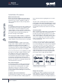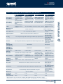
1
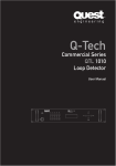
QA SERIES
QA 1004 | QA 2004 | QA 3004 | QA 4004
POWER AMPLIFIERS
user manual
QA SERIES
User Manual
CONTENTS / SAFETY
Contents
Safety
02-03
Introduction to QA Series
04
Connections
05
Amplifer installation information
06-07
Installation procedure
08-09
System configuration diagrams
09-10
Specifications
11
Safety Precautions
Carefully read the user manual
fully prior to use. Improper use can
cause damage to the amplifier and
any speakers attached to it. Please
be aware of correct wiring and
configurations as directed in the
Installation section of this manual.
Do not attempt to clean any plastic
parts with solvents or petrochemical
based cleaners.
Installation allowing direct
precipitation is not advised and
installation practise must prevent
liquids from entering the box.
Do not place sources of heat on or
around the amplifier such as lighting
equipment or smoke machines, and
where possible please keep out of
direct sunlight.
Do not place magnetic sensitive
equipment on or around amplifiers
The power voltages inside this
device are high and could cause
serious injury or death if touched
while the power is connected. Do
not open the amplifier case as there
are no user serviceable parts inside.
User Manual
QA Series
Power Amplifiers
QA SERIES
User Manual
1. Read all the documentation accompanying your
amplifier before operating.
6. Do not locate amplifiers close to sources of heat
or moisture.
2. Make absolutely sure the power supply is wired
correctly. This can be done with a commercially
available power supply tester. This especially
applies to three-phase distribution boards where
an incorrectly wired or intermittent neutral line
can cause excessive voltages causing permanent
damage to any 230-110 volt equipment connected
to it. It is good practice to test the power for polarity
and voltage range. Faulty wiring is commonly the
source of many audio difficulties.
7. Keep air intake area clear. It is good practice to
clean filter regularly and occasionally check the
amplifier is not clogged with dust. A hot amplifier
rack is a sign of inadequate maintenance or poor
installation.
3. Always operate the amplifier with the earth
or ground connected. When powered from a
generator, make sure there is a viable earth
connection.
4. Check that the external power wiring is in good
condition. Do not connect to damaged or frayed
wiring.
5. Confirm that the amplifier outputs are correctly
connected before operating. This particularly
applies to multiple speaker arrays here incorrect
wiring can lead to an accidental parallel connection
to another amplifier’s output causing damage to
both amplifiers.
Register Your Product
Thank you for choosing Quest. Please take the time
to complete your procuct registration card which
is included with the packaging. Registering your
Quest Engineering product will:
8. Occasionally check the cooling fans are
functioning. If an amplifier shuts down as a result
of excessive heat, distorts or is not sounding as it
should, check the speaker wiring, power supply,
(too low or too high), fan operation and input gain
structure for non standard setup.
9. Check your amplifier rack is clear of loose cable
ties, screws and stray wirers that can obstruct fans
or allow entry of anything that can cause short
circuit.
SAFETY
Installation Precautions
3
10. The amplifier should be returned to Quest Audio
service centre for service by qualifier personnel if
service is required.
11. Output voltages from the QA Series are
potentially high. Use only well insulated quality
speaker cable of suitable gauge. (See section
covering installation and wiring recommendations)
• CONFIRM YOUR WARRANTY
• REGISTER YOUR PRODUCT
• PROTECT YOUR NEW PRODUCT
QA Series
Power Amplifiers
User Manual
QA SERIES
User Manual
INTRODUCTION TO QA
Quest QA Series Power Amplifiers
4
Introduction
Congratulations on your purchase of a new
QA Series professional power amplifier. Quest
Engineering QA Series amplifiers are engineered
and built to a standard that will satisfy the most
demanding environments of both mobile live sound
and permanent installation audio.
Unpacking
Please inspect the amplifier carefully immediately
after unpacking. If you find any damage, notify your
supplier/dealer immediately. Only the shipper may
file a damage claim with the carrier for damage
incurred during shipping. Be sure to save the carton
and all packing materials for the carrier’s inspection.
For your safety and continuing reliability of
your Quest amplifier, please read all the safety
instructions and familiarise yourself with the
amplifiers functions and installation procedure
section before installing and operating the amplifier.
If your packing materials are in good condition,
please save them. If you ever need to ship the unit
back to Quest Engineering or an authorised service
centre, you are advised to use the original factory
packing.
Attention to detail
In order to maintain strict quality assurance
standards, all QA Series amplifiers are built and
tested in Quest Engineering’s own manufacturing
facility. Electronic components are the finest grade
available, and sub-assemblies are tested at every
stage before final assembly. Each amplifier is then
subjected to stress testing before shipping.
It follows that if your audio installation is completed
with the same attention to detail, your amplifier will
deliver its best results. It is recommended to make
sure all the mixers and signal processors in the
signal chain to the amplifier are set correctly. Clean
un-distorted power will not just sound better; it will
also help your speakers give you a long service life.
User Manual
QA Series
Power Amplifiers
QA SERIES
User Manual
CONNECTIONS
,
+
*
)
’
(
-
.
Lk
Lm
Lo
Lp
5
CAUTION
OFF
35Hz
80Hz
STEREO PARALLEL BRIDGE
HIGH PASS -A
OFF
80Hz
1.4V
32dB
OUTPUT A
26dB
GAIN
MODE
RISK OF ELECTRIC SHOCK
DO NOT OPEN
110Hz
LOW PASS -A
LINK A
INPUT A
PIN1: SIGNAL GND
PIN2: SIGNAL +
PIN3: SIGNAL -
BRIDGE
MODEL:
OUTPUT ASSIGNMENT
PIN 1+ :
SIGNAL
GROUND
PIN 1- :
Push To Reset
HIGH PASS -B
OFF
35Hz
80Hz
LOW PASS -B
OFF
80Hz
GROUND
LIMITER
110Hz
ON
OFF
LIFT
OUTPUT B
GROUND
DESIGNED BY QUEST ENGINEERING,AUSTRALIA
LINK B
INPUT B
N2388
/
Ll
1. ON/OFF Switch.
2. LEVEL Control of the input level of the
external signal in 3dB increments.
3. POWER Status available.
4. SIGNAL Signal status indicators: These LEDs
indicate signal presence for both the inputs of
channel A and B.
5. PEAK Status indicates when amplifier is
approaching clipping.
6. PROTECT The protect LED indicates that
one of the various amplifier protection circuits
has been activated.*If LED remains on
please return amplifier to a certified service
technician.
7. INPUTS Channel A/B balanced XLR inputs:
pin 1 ground, pin 2 + and pin 3 8. HIGH PASS FILTER Selectors for A & B.
9. LOW PASS FILTER Seclectors for A & B.
Ln
~ 220
240V 10A 50/60Hz
Lq
10. MODE This switches amplifier operational
mode from Stereo/Parallel Mono or Bridge
Mono. Input is across channel A. Minimum
speaker impedance is 8Ω in bridge mode.
Please refer to page 7 of this manual for
correct wiring instructions.ALWAYS SWITCH
OFF AMPLIFIER BEFORE OPERATING
BRIDGE SWITCH .
11. LIMITER Switches between off and on.
12. GAIN Input switch to calibrate mixer line level
to amplifier input sensitivity.
13. GROUND Seperates electrical earth from that
of chassis ground.
14. OUTPUTS Channel A/B and Bridge Outputs.
Speakon NL4 connectors output on pin1+
and 115. RESET Push circuit breaker to reset amplifier.
16. MAINS INPUT Main power input IEC.
SWITCH OFF AMPLIFIER BEFORE OPERATING
BRIDGE SWITCH
QA Series
Power Amplifiers
User Manual
QA SERIES
User Manual
INSTALLATION
Notes for better
amplifier performance
6
• Amplifier gain
The amplifier should always be operated with the input
level controls set at maximum. The only departure from
this practice is where the internal filters/crossover is
engaged in a bi-amp configuration, where it may be
necessary to turn down the high frequency side of
the amplifier. If the amplifier needs to be calibrated, to
match a mixer line level output, the gain switch on the
back of the amplifier can be switched to the correct
line level.
The objective of correct gain settings is to have all the
segments of the audio chain from the preamplifier/
equalisers/compressors/crossovers matched to the
amplifier. A test tone should take every link in the chain
to 0 dB or +4 dB at the same input level. This way, a
mixer VU indicator is a real visual clue as to how hard
the whole system is running and no single element will
be adding distortion before the system is at full power.
Some brands of speaker system are designed to
be monitored and controlled by a dedicated system
controller that is wired directly to the output of the
amplifier. These systems measure both the input
and output from the amplifier and monitor the signal
for best results from the speaker system. To engage
the amplifier’s limiter will interfere with the controllers
sensing circuit, so the amplifier limiter must be
disengaged.
• The air intakes
The two filtered air intakes have removable filters for
cleaning. The air intakes should be unobstructed and
allow the free flow of air.
• High- and low-pass filters
The filter system in a QA series amplifier is a basic
switchable high/low pass crossover. It can also be
used to filter out sub-harmonic low bass frequencies
the speaker system cannot reproduce and waste
amplifier power. It is particularly recommended to
switch in the 35 Hz High Pass filter when the amplifier
is being used to power band-pass type bass boxes.
The amplifier can be used to power a bass system
without the need for an electronic crossover by
switching the high-pass to 35Hz and the low-pass to
80 or 110Hz. The input link A/B XLR connectors at the
back of the amplifier will remain full-range, so a fullrange signal can be daisy chained to another amplifier
or powered speaker.
• Amplifier limiter
The switchable limiter is designed to prevent the
amplifier from clipping or distorting, there by causing
speaker damage. It should always be engaged except
in the circumstance where the amplifier is being used
in conjunction with an amplifier sensing speaker
system controller.
User Manual
QA Series
Power Amplifiers
The filters should be removed and cleaned as needed.
Running the amplifier without the filters will allow the
amplifier to fill with dust and foreign particles and could
void the warrantee under some circumstances.
• Rack-mounting amplifiers for the road
The Chassis of the QA series is fabricated from Q235
Cold Steel Rolling and is quite durable. However,
suspending an amplifier in free space in a rack
and then vibrating in the back of a truck for long
rough journeys may cause fatigue to the front panel
mounting. It is essential that the amplifier be supported
from the front and rear in rack-mounting especially
when the amplifier rack is to be transported. Failure
to install correctly may void warrantee. IMPORTANT:
Clean air filters regularly and always allow
adequate ventilation and do not block air flow to
amplifier!
2" minimum all around
AIR
FLOW
↑
2"
↓
←2"→
rack cabinet
AIR
FLOW
Parallel Mono is selected when you have an odd
number of speakers, such a three. Instead of leaving
the amplifier in stereo two-channel mode and driving
two on one side and one on the other. By selecting
Parallel Mono you can parallel all three and drive them
with equal power when connected to either or both
speaker outputs. Parallel mono is also more desirable
for the amplifier for speaker loads of 3-4Ω.
Care must be taken with speaker connections to
never have the amplifier outputs joined together
by a daisy chain of speaker connections . In this
configuration channel A level control is also used to
control amplifier level.
AIR
FLOW
AMPLIFIER
(TOP VIEW)
←2"→
Bridge Mono is elected when you need to get the
most power available when driving a total load of 8 Ω
or more.
In this configuration channel A level control is used to
control amplifier level.
AIR
FLOW
• Bridge/Parallel mono
The Bridge/Parallel mono mode is selected to convert
the two-channel amplifier into a mono amplifier of
greater power. This configuration would be selected
when for example more power is needed to drive
sub bass boxes to higher power. The functional
difference between the bridge mono and parallel mono
is determined by the speaker impedance of your
intended speaker system.
INSTALLATION
QA SERIES
User Manual
7
• Recommendations for speaker cables
Speaker cable needs to be as heavy gauge as
conveniently possible for low-loss results.
Light gauge cable (below 1.5mm) will create extra
resistance and waste amplifier power–this particularly
applies to long speaker runs. The damping factor
statistic (“punch” for the non technical) is greatly
diminished so keep your speaker cables short and fat.
Quality microphone cable will also lower noise and
improve high frequency response
Using the guidlines below, select the appropriate size of
wire based on the distance from amplifier to speaker
distance
wire size
indicitive
up to 25 ft
16AWG
25-40 ft
14AWG
41-60 ft
12AWG
61-100 ft
10AWG
101-150 ft
8AWG
151-250 ft
6AWG
CAUTION: Never use shielded cable for output wiring
QA Series
Power Amplifiers
User Manual
QA SERIES
User Manual
INSTALLATION
Installation Procedure
8
Mains Power Connection
Before connecting the amplifier to the mains power,
make certain that the voltage corresponds with that
indicated on the rear of the amplifier. A variation of
10% is acceptable. Refer to safety warnings before
switching on.
Power Up
It is standard procedure to power up the amplifiers last
and shut down first. The QA series amplifiers feature
turn on delays as the power up diagnostic circuits
search for faults, so turn on “thump” is avoided. The
speaker outputs are switched into circuit once checks
are complete and normal operating voltages are
present at all stages of the amplifier.
When powering up multiple amplifiers, a staged turn
on is suggested as the power surge of simultaneously
switching on multiple amplifiers can exceed the power
supply capability causing circuit breakers to disengage.
Power Requirements
The QA Series amplifier is capable of high output
voltages. When multiple amplifiers will be operating
simultaneously, make sure the power supply is
adequate for all amplifiers to draw full power. In this
case three phase power of sufficient Amperage supply
capacity will give best results from your amplifiers.
In the case where power is to be supplied from mobile
generators, It may help to “load the generator” with
some lighting to create a reserve of power from
the generator for the amplifiers. Amplifiers do not
necessarily draw high continuous power as lighting
will, but have a high demand for dynamic power
and can draw very high amounts of current for short
durations. If the power in not available, distortion and
reduced performance will result.
Rack mount installation
In permanent installation or mobile rack mounting it
is recommended to secure the amplifier from both
front and rear rack mounting facilities. For mobile
application, this practice is absolutely essential.
Damage to the amplifier caused by incorrect rack
mount installation or transit damage is not covered by
the warrantee.
Installation and electrical interference
Avoid installing your amplifier near sources of magnetic
fields such as radio transmitters, welding equipment,
User Manual
QA Series
Power Amplifiers
high current transformers, lighting dimmers or electric
motors.
All signal cables should be physically isolated from
power cables and all audio and amplifier power should
be supplied via a circuit separate from lighting or stage
machinery power. Failure to observe this standard
may generate unwanted noises and hum to the audio
system.
Connecting cables
When connecting the audio system, use only balanced
three conductor signal cable of high quality (screen
pin1 plus two signal carriers pin2/3). Low cost cable is
more inclined to pick up radio frequencies and noise
under certain conditions. For speaker cabinets, always
use two core copper high current cables of suitable
length. The thicker the copper core, the less the loss
on a long speaker line.
It follows to not make speaker cable runs longer than
necessary. Long runs of thin cable will greatly reduce
the excellent damping factor of the QA series amplifiers
causing a loss of “punch” in the bass response. The
rule of thumb is to use as thick a copper core as is
practical. It is impossible for a cable to have too much
copper but too little will cause losses of power and
reduced damping factor. Unnecessarily long speaker
cable runs will have the same effect, especially when
left in a tight coil from a high powered amplifier.
1. BALANCED
GND
1
2
SHIELD
3
2
FROM
PREAMPLIFIER
I NP U T
2. UNBALANCED
1
+
3
+
FROM
P RE A M P L I F I E R
I N PUT
+
+
SHIELD
SHIELD
1. Balanced input connector wiring.
2. Unalanced input connector wiring.
Bridge mono operation
In Bridge mono mode, the output of channel A input
buffer amplifier is connected to both channel A and
channel B power amplifiers. The signal is routed in a
manner to bring the channels onto opposite polarity to
QA SERIES
User Manual
each other. The A channel handles the positive voltage
swing and the B channel becomes the negative, thus
doubling the output voltage swing. Via the “bridge
output” speaker connector, the speaker is now
connected across the two channels.
Output is via the middle Speakon connector. The
output signal is across pins number 1+,1-.
Power is proportional to the square of the voltage
swing, so four times the output power is possible. The
reality is that this would exceed the capability of the
output stage but a considerable increase in output will
result all the same.
ALWAYS SWITCH OFF AMPLIFIER BEFORE
OPERATING BRIDGE SWITCH
3. SPEAKON CONNECTOR WIRING
2+
The minimum load impedance in bridge mono
mode is 8Ω
12-
Caution: In this mode output voltages are high
enough to constitute a shock hazard.
1+
INSTALLATION
Wiring will need to conform to CLASS 1 wiring
standards. Check your local electrical codes for the
appropriate electrical standards.
3. Speakon input and output connector wiring.
9
System configuration diagrams
Stereo Operation
STEREO
MODE
CAUTION
OFF
35Hz
80Hz
STEREO PARALLEL BRIDGE
80Hz
1.4V
MODE
HIGH PASS -A
OFF
32dB
26dB
GAIN
OUTPUT A
RISK OF ELECTRIC SHOCK
DO NOT OPEN
110Hz
LOW PASS -A
LINK A
INPUT A
PIN1: SIGNAL GND
PIN2: SIGNAL +
PIN3: SIGNAL -
MODEL:
BRIDGE
OUTPUT ASSIGNMENT
PIN 1+ :
SIGNAL
PIN 1- :
GROUND
Push To Reset
HIGH PASS -B
OFF
35Hz
80Hz
OFF
80Hz
GROUND
LIMITER
LOW PASS -B
110Hz
ON
OFF
LIFT
GROUND
DESIGNED BY QUEST ENGINEERING,AUSTRALIA
LINK B
INPUT B
OUTPUT B
~ 220
240V 10A 50/60Hz
QA Series
Power Amplifiers
User Manual
QA SERIES
User Manual
Parallel-Mono Operation
PARALLEL
MODE
SWITCH AMPLIFIER OFF BEFORE ENGAGING MONO/BRIDGE SWITCH
OR SERIOUS AMPLIFIER DAMAGE WILL RESULT
CAUTION
OFF
35Hz
80Hz
STEREO PARALLEL BRIDGE
1.4V
MODE
HIGH PASS -A
OFF
80Hz
32dB
26dB
GAIN
OUTPUT A
RISK OF ELECTRIC SHOCK
DO NOT OPEN
110Hz
LOW PASS -A
LINK A
INPUT A
PIN1: SIGNAL GND
PIN2: SIGNAL +
PIN3: SIGNAL -
MODEL:
BRIDGE
OUTPUT ASSIGNMENT
PIN 1+ :
SIGNAL
PIN 1- :
GROUND
Push To Reset
HIGH PASS -B
INSTALLATION
OFF
35Hz
80Hz
80Hz
GROUND
LIMITER
LOW PASS -B
OFF
110Hz
ON
OFF
LIFT
GROUND
OUTPUT B
DESIGNED BY QUEST ENGINEERING,AUSTRALIA
LINK B
~ 220
INPUT B
240V 10A 50/60Hz
10
Bridge-Mono Operation
BRIDGE
MODE
SWITCH AMPLIFIER OFF BEFORE ENGAGING MONO/BRIDGE SWITCH
OR SERIOUS AMPLIFIER DAMAGE WILL RESULT
CAUTION
OFF
35Hz
80Hz
STEREO PARALLEL BRIDGE
HIGH PASS -A
OFF
80Hz
1.4V
32dB
26dB
GAIN
MODE
OUTPUT A
RISK OF ELECTRIC SHOCK
DO NOT OPEN
110Hz
LOW PASS -A
LINK A
INPUT A
PIN1: SIGNAL GND
PIN2: SIGNAL +
PIN3: SIGNAL -
MODEL:
BRIDGE
OUTPUT ASSIGNMENT
PIN 1+ :
SIGNAL
GROUND
PIN 1- :
Push To Reset
HIGH PASS -B
OFF
35Hz
80Hz
LIMITER
LOW PASS -B
OFF
80Hz
110Hz
ON
GROUND
OFF
LIFT
GROUND
DESIGNED BY QUEST ENGINEERING,AUSTRALIA
LINK B
User Manual
QA Series
Power Amplifiers
INPUT B
OUTPUT B
~ 220
240V 10A 50/60Hz
QA SERIES
User Manual
QA 1004
QA 2004
QA 3004
QA 4004
Rated Power
(2 x 8 Ohms)
290 W per channel
@ 1 kHz at <0.1%
T.H.D.both channels
driven
490 W per channel
@ 1 kHz at <0.1%
T.H.D. both channels
driven
660 W per channel @ 1
kHz at <0.05% T.H.D.
both channels driven
1,090 W per channel
@ 1 kHz at <0.05%
T.H.D. both channels
driven
Rated Power
(2 x 4 Ohms)
575 W per channel
@ 1 kHz at <0.1%
T.H.D.both channels
driven
870 W per channel @
1 kHz at <0.1% T.H.D.
both channels driven
1100 W per channel @
1 kHz at <0.05% T.H.D.
both channels driven
2,000 W per channel @
1 kHz at <0.05% T.H.D.
both channels driven
T.H.D.
<0.1%@250 W per
channel from 20 HZ
to 20 kHz
>0.5% @ 400 W per
>0.1% @ 400 W per channel from 20 Hz to 20 kHz channel from 20 Hz to
20 kHz
Minimum Load
Impedance
4 Ohms – sine wave
4 Ohms – sine wave
Phase Response
+5 to -15 from 20 Hz to 20 kHz
+20 to -25 from 20 Hz
to 20 kHz
Input Impedance
20k Ohms, balanced; 10k Ohms, unbalanced
20k Ohms balanced
10k Ohms unbalanced
Cooling
Two temperature dependant variable speed 80mm high output DC fans
Controls
Two front panels attenuators, rear panel mode switch and gain select switch
Two temperature
dependant variable
speed 120mm high
output DC fans
Two front panels
attenuators, rear panel
mode switch and gain
select switch
Hi Pass:
Linkwitz-Reily
(24 db/Octave)
Off/35/80 Hz
Off/35/80 Hz
Low Pass:
Linkwitz-Reily
(24 db/Octave)
Off/80/110 Hz
Off/80/110 Hz
Voltage Gain
@ 0.775V
29 dB or 24 dB
Crosstalk
Hum and Noise
35 dB or 29 dB
38 dB or 32 dB
>-60 dB @ 1 kHz at rated power @ 8 Ohms
>-60 dB @ 1 kHz at
rated power @ 8 Ohms
>-60 dB @ 1 kHz at
rated power @ 8 Ohms
>-105 dB, “A” weighted >-107 dB, “A”
weighted referenced to
referenced to rated
rated power @ 8 Ohms
power @ 8 Ohms
>-107 dB, “A” weighted
referenced to rated
power @ 8 Ohms
>-104 dB, “A”
weighted referenced to
rated power @ 8 Ohms
Slew Rate
>30V/us
>40V/us
Damping Factor
(8 Ohms)
>500:1 @ 20 Hz - 1 kHz >700:1 @ 20 Hz - 1 kHz
Protection
32 dB or 26 dB
XLR, Speakon speaker output, 240/230 V 16 amps IEC mains
Construction
Dimensions
11
>44V/us
>800:1 @ 20 Hz - 1 kHz
Thermal, DC, turn-on bursts, subsonic, incorrect loads
Connectors
SPECIFICATIONS
Quest Engineering QA Series Amplifiers: Specifications*
Thermal, DC, turn-on
bursts, subsonic,
incorrect loads
XLR, Speakon speaker
output, 240/230 V 20
amps IEC mains
Cold Steel Rolling + Machined aluminium front panel
Cold Steel Rolling +
Machined aluminium
front panel
89 x 483 x 496 mm
132 x 483 x 496 mm
Net Weight
17 kg
21 kg
23 kg
35 kg
Packaged
Shipping Weight
20 kg
23 kg
26 kg
38 kg
* All specifications are correct at time of printing, Quest Engineering reserves the right to change
specifications at any time and won’t be held responsible for any typographic errors in this publication.
QA Series
Power Amplifiers
User Manual
www.questaudio.net