1
INSTALLATION REQUIREMENTS/SPECIFICATIONS
•
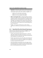
Fiber optic budget is the combination of the optical loss due to the fiber
optic cable, in-line splices, and fiber optic connectors (the loss for each
splice and connector is typically 1 dB or less).
•
Propagation delay is the amount of time it takes a packet to travel from
the sending device to the receiving device. Total propagation delay
allowed for the entire network is 25.6 µsec. If the total propagation
delay between any two nodes on the network exceeds 25.6 µsec, then
bridges should be used.
•
When using single mode fiber optic cable, segment lengths up to 10
km are possible if system budgets are met. However, IEEE 802.3
FOIRL specifications allow for a maximum length of 1 km.
2.3.4
Thin-Net Network Requirements
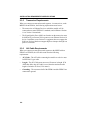
When you connect a Thin-net segment to the MRXI with a Coax Interface
Module (EPIM-C), the following network requirements must be met:
•
Cable Type - 50 ohm RG-58A/U type coaxial cable must be used
when making up a thin-net cable segment.
•
Length - The thin-net segment must be no longer than 185 meters.
•
Terminations - A 50 ohm terminator must be connected to the far end
of each thin-net segment.
•
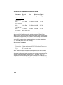
Connections - A maximum of 29 tee-connectors may be used
throughout the length of cable segment for host connections. If an
excessive number of barrel connectors are used within the cable
segment, such as finished wall plates with BNC feed-throughs, then a
reduced number of host connections may be required. For special
network design, contact Cabletron Systems Technical Support.
•
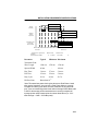
Grounding - For safety, only one end of a thin-net segment should be
connected to earth ground. Connection to earth ground at more than
one point on the segment could produce dangerous ground currents.
The BNC ports of the Coaxial Interface Modules are not connected to
earth ground.
Warning: Do not connect the shield at both ends of a thin net segment to
ground. Only one end of the shield should be connected to earth ground.
Multiple ground paths can introduce noise or a hazardous voltage
potential onto the cable.
2-5