1
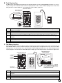
B. Tip & Ring Interface
The HD-1 can be used to dial touch tones directly on a Tip & Ring interface (C.O. line, analog PABX/KSU extension, etc.), it is necessary to change from the default handset cord to the Tip/Ring interface cord. To obtain an HD-1 Tip/Ring interface cord, contact
Viking Electronics Technical Support at: 715-386-8666 (part number: 260597, $5.00 each).
Internal View of the HD-1
Modular Handset Jack or
Modular Tip/Ring Jack
J1 Handset Interface
Connector
J1
J2
J2 Tip/Ring Interface
Connector
Pins: 10 9 8 7 6 5 4 3 2 1
4 3 2 1
C B A
1
2
3
4
5
6
7
8
9
0
#
HANDSET DIALER
Model HD-1
Battery OK
VIKING©
9V Battery
Wiring Protocol
Switch
Step 1. Obtain an HD-1 Tip/Ring interface cord (6 ft cord with 4 pin connector, RJ11C plug and jack) from Viking Technical
Support: 715-386-8666.
Step 2. Remove the 4 screws on the back of the HD-1 and remove the cover.
Step 3. Locate J1 (as shown above) and cut the wires on pins 1-8 of the J1 connector. Then remove the cord and modular
handset jack connected to J1. Caution: Do NOT cut the red and black battery wires connected to J1 pins 9 & 10.
Step 4. Connect the Tip/Ring interface cord to J2. Note: Connector position 1 to pin 1 of J2. Slide the modular Tip/Ring jack
into place.
Step 5. Slide Wiring Protocol Switch to position “C” as shown.
Step 6. Replace the back cover and connect the modular cord from the phone to the modular jack on the HD-1.
Step 7. Plug the HD-1 cord into the modular jack the phone was connected to.
C. Talk Battery Interface
With the optional PS-1A installed, the HD-1 is capable of supplying its own 24VDC Talk Battery to be used in conjunction with the
model RC-2A or RC-3 to create a stand alone door/gate security keypad control. This application will require the use of the HD-1
Tip/Ring interface cord and installation of the optional PS-1A. To obtain an HD-1 Tip/Ring interface cord, contact Viking Electronics
Technical Support at: 715-386-8666. To obtain a PS-1A power adapter, go to www.vikingelectronics.com and click on “Spare Parts”.
Model RC-2A or RC-3
Relay Controllers
Internal View of the HD-1
VIKING ©
J3 Talk Battery Interface
Connector
MODEL RC-2A
VIKING
ELECTRONICS
HUDSON, WI 54016
J4
ENTRY CODE
PROGRAMMING
SWITCHES
1
E
ON
789A
1
2
3
4
5
6
2
F0 1 2
E
F0 1 2
S2
S3
#
HANDSET DIALER
Model HD-1
Battery OK
Replaceable 9V
Alkaline Battery
3
F0 1 2
7
S1
0
E
BC D
8
C
BC D
7
N.C.
6
BC D
5
3456
9
C
3456
8
3 4
3456
7
2
COM
1
RELAY
CONTACTS
LINE IN
6
N.O.
5
EARTH
GND
4
REMOTE TOUCH TONE
RELAY CONTROLLER
PWR IN/OUT
12-24V AC/DC
3
789A
2
789A
1
POWER 12V DC
J3
J4 13.8V AC
Connection
for Optional PS-1A
VIKING©
9V Battery
For more information on the RC-2A,
retrieve Fax Back Document 160. For
more information on the RC-3, retrieve
Fax Back Document 165.
Step 1. Follow steps 1-3 as shown in section B above.
Step 2. Connect the Tip/Ring interface cord to J3. Note: Connector position 1 to pin 1 of J3. Slide the modular Tip/Ring jack
into place.
Step 3. Connect the PS-1A (13.8V AC adapter) to J4.
Step 4. Remove the 9V battery and discard.
Step 5. Re-assemble the HD-1.
Note: The Wiring Protocol Switch has no effect in the Talk Battery Interface mode.
3