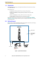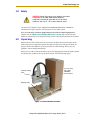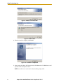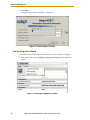
1
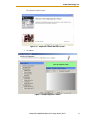
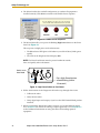
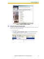
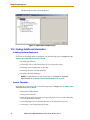
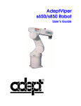
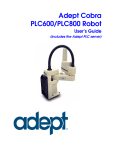
Adept Cobra
i600/i800 Robot
Quick Setup Guide
P/N: 03588-000, Rev D
May, 2010
Adept Technology, Inc.
1.0
Introduction
This Quick Setup Guide steps you through the installation and start-up of your Adept
Cobra i600/i800 robot.
The major steps are:
• Preparation, including Workcell Layout, Safety, and Unpacking
• Hardware Installation, including Mounting the Robot and System Cable
Connections
• Software Installation, including .NET Framework and Adept ACE
• System Start-Up, including turning on and moving the robot
During the installation and start-up process, refer also to the Adept Cobra i600/i800
Robot User’s Guide, shipped with each system, for complete information on all aspects
of your robot system.
2.0
Workcell Layout
Figure 1 shows a simple workcell layout with a user-supplied safety barrier and E-Stops
provided by the Front Panel and optional T2 pendant.
Adept Cobra
i600/i800 Robot
Safety Barrier
Restricted Area
Inside Safety
Barrier
24 VDC
STOP
R
200-240 VAC
Front Panel
T2 Pendant E-Stop #1
Optional, Install
terminator if
pendant not used
PC running
Adept ACE
E-Stop #2
Figure 1. Typical Workcell Layout
2
Adept Cobra i600/i800 Robot Quick Setup Guide, Rev D
Adept Technology, Inc.
3.0
Safety
WARNING: Adept Technology strictly prohibits installation
or operation of an Adept robot without adequate
safeguards according to applicable local and national
standards. See Figure 1 for a simple workcell layout.
You must read Chapter 2 in the Adept Cobra i600/i800 Robot User’s Guide for
information on topics related to safe operation of your robot system.
Refer to Connecting Customer-Supplied Safety and Power Control Equipment in
Chapter 6 of the Adept Cobra i600/i800 Robot User’s Guide. This section provides
details on connecting a user-designed E-Stop system to the XUSR connector on the robot.
4.0
Unpacking
Remove the top of the robot crate. Do not remove the bolts that attach the robot to the
pallet. Inspect your equipment against the purchase order and verify that all items are
present and that the shipment is correct and free of visible damage. If there are any
problems, contact Adept immediately.
When you are ready to mount the robot, remove the shipping bolts from the pallet, and lift
the robot by the eyebolt on the top of the inner link. See the following figure.
Accessory Box
with Cables,
CD-ROMs,
Documentation
Eyebolt for lifting
robot
Shipping Pallet
Figure 2. Cobra i600 Robot on Pallet
Adept Cobra i600/i800 Robot Quick Setup Guide, Rev D
3
Adept Technology, Inc.
5.0
Mounting the Robot
Mount the robot on a rigid surface that will prevent vibration and flexing during robot
operation. Adept recommends a 25 mm (1 in.) thick steel plate, mounted to a rigid steel
tube frame. See the following figure for the mounting hole dimensions.
160
4X Ø 14
THRU
+0.015
2x R4 0
80
6
Use four M12 - 1.75 x 36 mm [85 N-m]
(or 7/16 - 14 UNC x 1.50 in. [50 ft-lb])
machine bolts to secure the robot.
Units in mm
10
45
160
200
50
Ø8
+0.015
6
0
234
90
338
Figure 3. Robot Mounting Hole Dimensions
Brake Release
and Diagnostic
Panel
Status LED
Joint 2
User Connector
Panel
Joint 3 Vertical
Z-Stroke
Amps-In-Base
(AIB) Chassis
Joint 4 Tool Flange
Rotational
Robot Interface
Panel
Joint 1
Mounting Bolts
(2 of 4)
Figure 4. Cobra i800 Components
4
Adept Cobra i600/i800 Robot Quick Setup Guide, Rev D
Adept Technology, Inc.
6.0
System Cable Connections
Open the Accessory Box and locate the AIB XPANEL cable, and RS-232 null modem serial
cable. Connect the system cables and peripherals as shown in Figure 5. Refer to Chapter 4
in the Adept Cobra i600/i800 Robot User’s Guide for AC power specifications and AC
wiring diagrams.
Parts used in System Cable Connections.
Part
Cable and Parts List
Part #
Part of:
Notes
A
AIB XPANEL Cable
04715-000
04081-000
standard, iCobra
B
XUSR Jumper Plug
04736-000
04081-000
standard, iCobra
C
Front Panel
30356-10358
90356-10358
standard, iCobra
D
Front Panel Cable
10356-10500
90356-10358
standard, iCobra
E
XMCP Jumper Plug
04737-000
04081-000
standard, iCobra
F
T1/T2 Bypass Plug
05004-000
G
T1/T2 Adapter Cable
05002-000
H
T2 (optional)
05215-103/
05215-110
04965-203/
04965-210
T2 option 3 m/10 m
J
AC Power Cable
04118-000
90565-010
user-supplied
K
24 VDC Power Cable
04120-000
90565-010
user-supplied
L
24 VDC, 6 A Power Supply
04536-000
90565-010
user-supplied
M
RS-232 Null Modem Serial Cable
04116-001
90565-000
standard, iCobra
Adept Cobra i600/i800 Robot Quick Setup Guide, Rev D
5
Adept Technology, Inc.
Steps in Cable Connections
Installation Procedure
Step #
Step Description
Part(s)
1
Connect AIB XPANEL cable to XPANEL on Robot Interface Panel.
A
2
Verify XUSR jumper plug is installed on XUSR connector.
B
3
Connect Front Panel cable to Front Panel and XFP connector.
C, D
4
If no T2, install XMCP jumper or T1/T2 bypass plug. Skip to 5.
E, F
4a
If you have T2, connect T1/T2 adapter cable to XMCP connector.
G, H
5
Connect user-supplied ground. See User's Guide for locations.
-
6
Connect 200-240 VAC to AC Input on Interface Panel; secure with clamp.
J
7
Connect 24 VDC to DC Input on Interface Panel.
K, L
8
Connect null modem serial cable to Interface Panel and serial port on PC.
M
XUSR for:
- User E-Stop/Safety Gate
B
- Muted Safety Gate
XUSR
- Jumper plug required
Jumper
when not used
Plug
Adept Cobra
i600/i800 Robot
2
XUSR
3
D
Front Panel
Cable
C
3
XFP
Front Panel
User-Supplied
Ground Wire
T1/T2 Adapter
Cable
4a
H
4a
XMCP
1
GND
G
4
F
T1/T2 Bypass Plug
T2 Pendant (optional)
XSLV
2
SmartServo
5
A
+24V
DC INPUT
(24 VDC)
AC INPUT
(200-240 VAC 1&)
XIO
XPANEL
RS-232
4
E
XMCP Jumper Plug
AIB
XPANEL
Cable
Either T1/T2 Bypass Plug or XMCP Jumper Plug
must be installed if T2 is not used
Robot Interface
Panel
1
1
85 - 264 VAC
Universal
Input
GND
L
K
24 VDC, 6 A
Power Supply
8
User-Supplied PC
running Adept ACE
200-240 VAC
10 A
single-phase
J
M
2
SmartServo
DC Power
Cable
AC Power
Cable
7
+24V
DC INPUT
(24 VDC)
6
RS-232 Null Modem Cable
for Robot to PC Connection
Figure 5. Cobra i600/i800 Robot System Cable Diagram
6
XSLV
Adept Cobra i600/i800 Robot Quick Setup Guide, Rev D
AC INPUT
(200-240 VAC 1&)
XIO
8
XPANEL
RS-232
Adept Technology, Inc.
7.0
Installing Adept ACE Software
You install Adept ACE software from the Adept Software CD-ROM. You will need
Microsoft .NET Framework. The Adept ACE Setup Wizard scans your PC for .NET, and
installs it automatically, if needed.
1. Insert the CD-ROM into the CD-ROM drive of your PC. If Autoplay is enabled,
the Adept Software CD-ROM menu is displayed - see Figure 6. If Autoplay is
disabled, you will need to manually start the CD-ROM.
NOTE: The online document that describes the installation process opens
in the background when you select one of software installation steps
below.
2. From the Adept Software CD-ROM menu, click Install the Adept ACE Software.
Figure 6. Adept ACE CD-ROM Startup Menu
3. The Adept ACE Setup wizard opens - see the following figure. Follow the
instructions as you step through the installation process.
Figure 7. Setup Welcome Screen
Adept Cobra i600/i800 Robot Quick Setup Guide, Rev D
7
Adept Technology, Inc.
Figure 8. Ready-to-Install Screen
Figure 9. Install Screen
4. When the install is complete, click Finish.
Figure 10. Installation Completed
5. After closing the Adept ACE Setup wizard, click Exit on the CD-ROM menu and
proceed to the Start-up Procedure.
NOTE: You will have to restart the PC after installing Adept ACE.
8
Adept Cobra i600/i800 Robot Quick Setup Guide, Rev D
Adept Technology, Inc.
8.0
Start-up Procedure
Turn On Power and Start Adept ACE
1. Manually move the robot joints away from the folded shipping position, similar
to the position shown on the cover of this Guide.
2. Turn on 200/240 VAC power.
DANGER: Make sure personnel are skilled and instructed refer to Chapter 2 in the Adept Cobra i600/i800 Robot
User’s Guide.
3. Turn on 24 VDC power to the robot. The Diagnostic Panel displays OK. The
Robot Status LED will be off. On older iCobras, it blinks green slowly.
4. Verify that the Auto/Manual switch on the Front Panel is set to Auto Mode. (See
Figure 16 on page 12.)
5. Turn on the user-supplied PC and start Adept ACE:
• Double-click the Adept ACE icon on your Windows desktop
or
• From the Windows Start menu bar, select
Start > Programs > Adept Technology > Adept ACE > Adept ACE.
6. Connect a serial (COM) cable from the PC to the robot interface panel.
7. On the Adept ACE Startup menu:
• Check Create New Workspace for iCobra at:
to make the connection to the Adept robot.
• Select the COM port to match the COM port being used on your PC. See the
following figure.
Figure 11. Adept ACE Startup Menu
Adept Cobra i600/i800 Robot Quick Setup Guide, Rev D
9
Adept Technology, Inc.
8. Click Open.
You will see the message “Working . . Please wait”.
Figure 12. Connecting to the iCobra
Use the Diagnostics Wizard
1. Double-click the iCobra object in the Folder pane of the Workspace Explorer.
2. In the object editor, select Configure > Diagnostics Wizard. See the following
figures.
Figure 13. Selecting the Diagnostics Wizard
10
Adept Cobra i600/i800 Robot Quick Setup Guide, Rev D
Adept Technology, Inc.
The Welcome window opens:
Figure 13-1. Diagnostics Wizard Welcome Screen
3. Click Next.
Figure 14. Adept Diagnostics Wizard
Adept Cobra i600/i800 Robot Quick Setup Guide, Rev D
11
Adept Technology, Inc.
4. The Wizard verifies the workcell configuration, to confirm all equipment is
installed correctly. Click Next to continue to the Enable Power sequence.
Figure 15. Diagnostics Enable Power Sequence
5. The Wizard then tells you to press the blinking High Power button on the Front
Panel. See Figure 16.
This step turns on high power to the robot motors.
• The Robot Status LED glows solid amber or, on older iCobras, blinks green
rapidly.
• The code on the Diagnostic Panel displays ON.
NOTE: The Front Panel button must be pressed within 10 seconds.
Press and quickly release the button.
Switch set to
Auto Mode
Press High Power button
when blinking (within
10 seconds)
Figure 16. High Power Button on Front Panel
6. Follow the directions in the Diagnostics Wizard to step through these items:
• Calibrate the robot
• Verify robot motions
• Verify digital input and outputs, if you have the XIO Terminal Block product
installed.
7. When you finish the Wizard, the robot is ready to use. See the following figure.
Go to Section 9.0 for details on running a sample application. Go to Section 10.0
to find additional information on using the robot and installing optional
equipment.
12
Adept Cobra i600/i800 Robot Quick Setup Guide, Rev D
Adept Technology, Inc.
Figure 17. Diagnostics Wizard Complete
9.0
Using the Sample Applications
You can run the sample application included with Adept ACE to learn how to use your
system. To load and run the application:
1. Start Adept ACE.
2. Select Tools > Application Samples > MicroV+ arm- or fixed-mount camera
to start the application sample for the iCobra.
Use of the application samples is covered in the AdeptSight Online Help.
Figure 18. Selecting Application Samples from the Tools Menu
Adept Cobra i600/i800 Robot Quick Setup Guide, Rev D
13
Adept Technology, Inc.
The following selections will be displayed:
Figure 19. Application Samples Menu
10.0 Finding Additional Information
Installing Optional Equipment
For details on installing optional equipment, see the following topics in Chapter 5 of the
Adept Cobra i600/i800 Robot User’s Guide:
• Installing end-effectors
• Connecting user air and electrical lines to User Connection Panel
• Mounting external equipment on the robot
• Mounting the robot solenoid option kit
• Installing adjustable hardstops
NOTE: For robot dimensions and specifications, see Chapter 8 - Technical
Specifications in the Adept Cobra i600/i800 Robot User’s Guide.
System Operation
For details on system operation, see the following topics in Chapter 6 of the Adept Cobra
i600/i800 Robot User’s Guide:
• Robot Status LED Indicator
• Status panel fault codes
• Brake Release button (located above diagnostic panel). To move Joint 3 manually,
press the Brake Release button.
• Connecting digital I/O on the XIO connector at the robot interface panel
• Connecting a user-designed E-Stop System
14
Adept Cobra i600/i800 Robot Quick Setup Guide, Rev D
Adept Technology, Inc.
Using the Configuration Manager Utility
The Configuration Manager Utility allows you to configure these functions on a Cobra
i600/i800 Robot: joint limits, hand open/close signals, and workcell obstacles. The utility
is accessed from the Configure menu in the iCobra object editor in Adept ACE.
NOTE: The Configuration Manager is covered in detail in the Adept ACE
Online Help.
1. Double-click the iCobra object in the Folder pane of the Workspace Explorer.
2. In the object editor, select Configure > Configuration Manager. See Figure 13.
The Configuration Manger window opens:
Figure 20. Configuration Manager Utility
How Can I Get Help?
Refer to the How to Get Help Resource Guide (Adept P/N 00961-00700) for details on
getting assistance with your Adept software and hardware. Additionally, you can access
information sources on Adept’s corporate web site:
http://www.adept.com
Adept Cobra i600/i800 Robot Quick Setup Guide, Rev D
15
P/N: 03588-000, Rev D
5960 Inglewood Drive
Pleasanton, CA 94588
925·245·3400