1
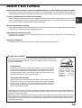
Warranty
While every effort has been made to make this document as accurate and helpful as possible, SHARP Corporation
makes no warranty of any kind with regard to its content. All information included herein is subject to change without
notice. SHARP is not responsible for any loss or damages, direct or indirect, arising from or related to the use of this
operation manual.
© Copyright SHARP Corporation 2001. All rights reserved. Reproduction, adaptation or translation without prior written
permission is prohibited, except as allowed under copyright laws.
Trademark Acknowledgments
Microsoft Windows, MS-DOS, and Windows NT are trademarks of Microsoft Corporation in the U.S.A. and other
countries.
Macintosh, Power Macintosh, Mac OS, LaserWriter, and AppleTalk are registered trademarks of Apple Computer, Inc.
IBM, PC/AT, and PowerPC are trademarks of International Business Machines Corporation.
Pentium is a registered trademark of Intel Corporation.
PCL is a trademark of the Hewlett-Packard Company.
PostScript® is a registered trademark of Adobe Systems Incorporated.
NetWare is a registered trademark of Novell, Inc.
All other trademarks and copyrights are the property of their respective owners.
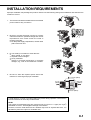
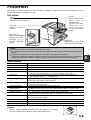
INSTALLATION REQUIREMENTS
Improper installation may damage this product. Please note the following during initial installation and whenever the
machine is moved.
1. The machine should be installed near an accessible
power outlet for easy connection.
2. Be sure to connect the power cord only to a power
outlet that meets the specified voltage and current
requirements. Also make certain the outlet is
properly grounded.
● For the power supply requirements, see the name
plate of the main unit.
3. Do not install your machine in areas that are:
● damp, humid, or very dusty
● exposed to direct sunlight
● poorly ventilated
● subject to extreme temperature or humidity
changes, e.g., near an air conditioner or heater.
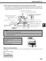
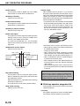
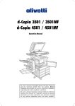
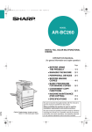
4. Be sure to allow the required space around the
machine for servicing and proper ventilation.
11-13/16" (30cm)
31-1/2"
(80cm)
23-5/8"
(60cm)
23-5/8" (60cm)
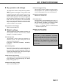
A small amount of ozone is produced within the printer during operation. The emission
level is insufficient to cause any health hazard.
NOTE:
The present recommended long term exposure limit for ozone is 0.1 ppm (0.2 mg/m3)
calculated as an 8 hr. time-weighted average concentration.
However, since the small amount that is emitted may have an objectionable odor, it is
advisable to place the copier in a ventilated area.
0-1
INSTALLATION REQUIREMENTS
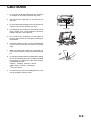
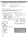
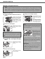
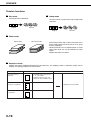
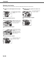
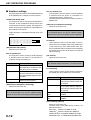
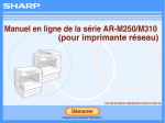
Moving this machine
Lift this machine at the positions shown in the illustration below and carry it horizontally.
CAUTION
Two people are required to lift and carry this machine.
The center of gravity of the machine is slightly to the left of the center of the machine when viewed from the front. If a
duplex module is installed the center of gravity will be even further shifted to the left. When lifting the machine be
careful to steady it to prevent it from toppling. Also be sure that all covers and the duplex module are securely closed
and latched before lifting.
If a duplex module is installed, do not lift the machine by the module as it may come off causing it and the machine to
drop.
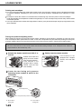
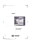
Remove the multi purpose drawer and lift at the positions shown in the illustration.
For removal and installation of the multi purpose drawer, see page 4-4. To avoid injury be sure to completely remove
the multi purpose drawer.
Front side
Rear side
Remove the multi
purpose drawer
in advance.
If the machine has been placed on a stand/paper drawer:
The stand/paper drawer is equipped with casters for moving. Unlock the adjusters of the stand/paper drawer and
gently move the machine taking care to steady it to prevent it from toppling.
For locking and unlocking the adjusters, see page 0-3.
CAUTIONS
The center of gravity of this machine is a little deviated to the left from the center. If the machine is not equipped
with a multi purpose drawer or a stand/paper drawer, take care in opening the left side cover (or the duplex
module) not to cause toppling of the machine.
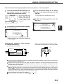
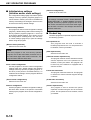
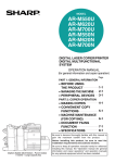
● Do not cover the ventilating holes of this machine. Do not install this machine in a location where these holes are
covered. If these holes are covered, heat will not be dissipated and a fire may be caused.
●
Ventilating holes
0-2
CAUTIONS
1. Do not touch the photoconductive drum. Scratches
or smudges on the drum will cause dirty prints.
2. The fusing unit is extremely hot. Exercise care in
this area.
3. Do not look directly at the light source of the scanner
module. Doing so may damage your eyes.
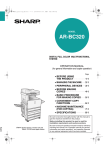
4. Five adjusters are provided on all optional stand/
paper drawer units. These adjusters should be
lowered until they contact the floor.
Fusing unit
5. Do not make any modifications to this machine.
Doing so may result in personal injury or damage to
the machine.
6. Since this machine is heavy, it is recommended that
it be moved by more than one person to prevent
injury.
7. When connecting this machine to a computer, be
sure to first turn both the computer and the machine
off.
8. Do not print anything which is prohibited from printing
by law. The following items are normally prohibited
from printing by national law. Other items may be
prohibited by local law.
● Money ● Stamps ● Bonds ● Stocks
● Bank drafts ● Checks ● Passports
● Driver's licenses
Adjuster
Lock
Release
9. Do not throw toner or a toner cartridge into fire. Toner
may be spattered, causing a burn.
0-3
CAUTIONS
Cautions on laser
Wave length
785 nm
+10 nm
−15 nm
Pulse times
North America: 35 cpm model: (4.1 µs ± 4.1 ns)/7 mm
45 cpm model: (5.7 µs ± 5.7 ns)/7 mm
Europe:
31 cpm model: (3.8 µs ± 3.8 ns)/7 mm
35 cpm model: (3.8 µs ± 3.8 ns)/7 mm
45 cpm model: (4.4 µs ± 4.4 ns)/7 mm
Output power
0.2 mW - 0.4 mW
At the production line, the output power of the scanner unit is adjusted to 0.4
MILLIWATT PLUS 8 % and is maintained constant by the operation of the Automatic
Power Control (APC).
Caution
This product contains a low power laser device. To ensure safety do not remove any cover or attempt to gain
access to the inside of the product. Refer all servicing to qualified personnel.
For North America:
SAFETY PRECAUTIONS
This Digital Equipment is rated Class 1 and complies with 21 CFR 1040.10 and 1040.11 of the
CDRH standards. This means that the equipment does not produce hazardous laser radiation. For
your safety, observe the precautions below.
●
Do not remove the cabinet, operation panel or any other covers.
●
The equipment's exterior covers contain several safety interlock switches. Do not bypass any
safety interlock by inserting wedges or other items into switch slots.
Caution
Use of controls or adjustments or performance of procedures other than those specified herein may result in
hazardous radiation exposure.
0-4
CAUTIONS
For Europe:
CLASS 1 LASER PRODUCT
LASER KLASSE 1
LUOKAN 1 LASERLAITE
KLASS 1 LASERAPPARAT
CAUTION
INVISIBLE LASER RADIATION
WHEN OPEN INTERLOCKS
DEFEATED. AVOID EXPOSURE
TO BEAM.
VORSICHT
UNSICHTBARE
LASERSTRAHLUNG WENN
ABDECKUNG GEÖFFNET UND
SICHERHEITSVERRIEGELUNG
ÜBERBRÜCKT. NICHT DEM
STRAHL AUSSETZEN.
ADVARSEL
USYNLIG LASERSTRÅLNING
VED ÅBNING, NÅR
SIKKERHEDSBRYDERE ER
UDE AF FUNKTION. UNDGÅ
UDSAETTELSE FOR
STRÅLNING.
VAROITUS!
LAITTEEN KÄYTTÄMINEN
MUULLA KUIN TÄSSÄ
KÄYTTÖOHJEESSA
MAINITULLA TAVALLA SAATTAA
ALTISTAA KÄYTTÄJÄN
TURVALLISUUSLUOKAN 1
YLITTÄVÄLLE
NÄKYMÄTTÖMÄLLE
LASERSÄTEILYLLE.
VARNING
OM APPARATEN ANVÄNDS PÅ
ANNAT SÄTT ÄN I DENNA
BRUKSANVISNING
SPECIFICERATS, KAN
ANVÄNDAREN UTSÄTTAS FÖR
OSYNLIG LASERSTRÅLNING,
SOM ÖVERSKRIDER GRÄNSEN
FÖR LASERKLASS 1.
CAUTION
VORSICHT
ADVARSEL
ADVERSEL
VARNING
VARO!
INVISIBLE LASER RADIATION WHEN OPEN AND INTERLOCKS DEFEATED.
AVOID EXPOSURE TO BEAM.
Laserstrahl
UNSICHTBARE LASERSTRAHLUNG WENN ABDECKUNG GEÖFFNET UND
SICHERHEITSVERRIEGELUNG ÜBERERÜCKT. NICHT DEM STRAHL AUSSETZEN.
USYNLIG LASERSTRÅLING VED ÅBNING, NÅR SIKKERHEDSAFBRYDERE ER
UDE AF FUNKTION. UNDGÅ UDSAETTELSE FOR STRÅLNING.
USYNLIG LASERSTRÅLING NÅR DEKSEL ÅPNES OG SIKKERHEDSLÅS BRYTES.
UNNGÅ EKSPONERING FOR STRÅLEN.
OSYNLIG LASERSTRÅLNING NÄR DENNA DEL ÄR ÖPPNAD OCH SPÄRRAR ÄR
URKOPPLADE. STRÅLEN ÄR FARLIG. BETRAKTA EJ STRÅLEN.
AVATTAESSA JA SUOJALUKITUS OHITETTAESSA OLET ALTTIINA NÄKYMÄTÖNTÄ
LASERSÄTEILYLLE. ÄLÄ KATSO SÄTEESEEN.
CLASS 1
LASER PRODUCT
LASER KLASSE 1
0-5
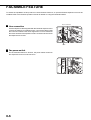
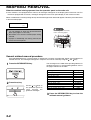
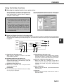
FACSIMILE FEATURE
To extend the capabilities of this product to include facsimile functions, an optional facsimile expansion kit must be
installed. Refer to the facsimile operation manual for details on using the facsimile features.
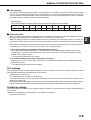
■ Line connection
Line connector
Use the telephone cable supplied with the facsimile expansion kit to
connect the machine to a telephone line. Connect the cable so that
the connector nearest to the noise suppression core is inserted into
the socket located of the expansion kit box. Insert the other end into
the telephone line socket.
TEL
LINE
Core
■ Fax power switch
For the facsimile features to function, the power switch located on
the expansion kit box must be turned on.
TEL
LINE
ON
OFF
0-6
Fax power
switch
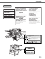
CONTENTS
Page
INSTALLATION REQUIREMENTS . . . . . . . . . . . . 0-1
●
Carrying this machine . . . . . . . . . . . . . . . . . . . . 0-2
CAUTIONS . . . . . . . . . . . . . . . . . . . . . . . . . . . . . . 0-3
FACSIMILE FEATURE . . . . . . . . . . . . . . . . . . . . . 0-6
CONTENTS . . . . . . . . . . . . . . . . . . . . . . . . . . . . . 0-7
CHAPTER 1
BEFORE USING THE PRODUCT
INTRODUCTION . . . . . . . . . . . . . . . . . . . . . . . . . 1-2
MAIN FEATURES . . . . . . . . . . . . . . . . . . . . . . . . . 1-3
PART NAMES AND FUNCTIONS . . . . . . . . . . . . 1-4
●
●
●
●
●
Exterior . . . . . . . . . . . . . . . . . . . . . . . . . . . . . . . 1-4
Interior . . . . . . . . . . . . . . . . . . . . . . . . . . . . . . . . 1-5
Part names and functions of
peripheral devices . . . . . . . . . . . . . . . . . . . . . . . 1-6
Operation panel of the main unit . . . . . . . . . . . . 1-9
Operation panel of the scanner module . . . . . 1-12
●
Touch panel (on the scanner module) . . . . . . 1-13
LOADING PAPER . . . . . . . . . . . . . . . . . . . . . . . . 1-16
●
●
●
●
●
●
Loading paper in paper tray 1 . . . . . . . . . . . . . 1-16
Changing the paper size in paper tray 1 . . . . . 1-16
Specifications of paper trays . . . . . . . . . . . . . . 1-17
Setting the paper size and type . . . . . . . . . . . 1-19
Loading paper in the multi purpose drawer . . . 1-21
Specifications (multi purpose drawer) . . . . . . . 1-23
●
Loading paper in the stand/
3 x 500 sheet paper drawer . . . . . . . . . . . . . .
● Specifications
(stand/3 x 500 sheet paper drawer) . . . . . . . .
● Loading paper in the stand/
MPD & 2000 sheet paper drawer . . . . . . . . . .
● Specifications
(stand/MPD & 2000 sheet paper drawer) . . . .
ADDING TONER . . . . . . . . . . . . . . . . . . . . . . . . .
STORAGE OF SUPPLIES . . . . . . . . . . . . . . . . .
1-23
1-23
CHAPTER 2
PRINTING FROM A COMPUTER
CONNECTING TO A COMPUTER . . . . . . . . . . . . 2-2
SOFTWARE FOR WINDOWS . . . . . . . . . . . . . . . 2-2
INSTALLING PRINTER DRIVERS AND
PRINTER UTILITIES . . . . . . . . . . . . . . . . . . . . . . 2-3
UNINSTALLING PRINTER DRIVERS AND
PRINTER UTILITIES . . . . . . . . . . . . . . . . . . . . . . 2-3
INSTALLING PRINTER DRIVERS USING PLUG &
PLAY OR THE “ADD PRINTER WIZARD” . . . . . . 2-4
● Before installation . . . . . . . . . . . . . . . . . . . . . . . 2-4
SETTING THE PRINTER DRIVER . . . . . . . . . . . .
Printer driver settings under Windows
(selecting and setting print conditions) . . . . . . .
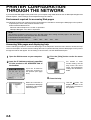
PRINTER CONFIGURATION THROUGH
THE NETWORK . . . . . . . . . . . . . . . . . . . . . . . . . .
● Environment required for accessing
Web pages . . . . . . . . . . . . . . . . . . . . . . . . . . . .
● Accessing Web pages and displaying help . . . .
2-5
●
2-5
2-6
2-6
2-6
●
Items and outline of menu frame of
Web pages . . . . . . . . . . . . . . . . . . . . . . . . . . . . 2-7
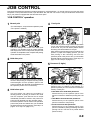
JOB CONTROL . . . . . . . . . . . . . . . . . . . . . . . . . . 2-9
●
●
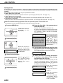
“JOB CONTROL” operation . . . . . . . . . . . . . . . . 2-9
Hold job list . . . . . . . . . . . . . . . . . . . . . . . . . . . 2-10
●
Printer account control . . . . . . . . . . . . . . . . . . 2-12
USING THE MACHINE AS A POSTSCRIPT
PRINTER . . . . . . . . . . . . . . . . . . . . . . . . . . . . .
● Using the printer in the Windows
environment . . . . . . . . . . . . . . . . . . . . . . . . .
● Using the printer in the Macintosh
environment . . . . . . . . . . . . . . . . . . . . . . . . .
2-13
2-13
2-15
1-24
CHAPTER 3
1-24
1-25
1-25
PRINTER BASIC SETTINGS
MAKING CONFIGURATION SETTING . . . . . . . . 3-2
●
●
●
Operation procedure common to all printer
configuration settings (items that can be set
from the operation panel) . . . . . . . . . . . . . . . . . 3-2
Default settings . . . . . . . . . . . . . . . . . . . . . . . . . 3-4
PCL settings . . . . . . . . . . . . . . . . . . . . . . . . . . . 3-5
●
PostScript settings . . . . . . . . . . . . . . . . . . . . . . 3-5
CUSTOM SETTINGS . . . . . . . . . . . . . . . . . . . . . . 3-6
●
●
Operation procedure common to all custom
settings (items that can be set from the
operation panel) . . . . . . . . . . . . . . . . . . . . . . . . 3-6
Setting items . . . . . . . . . . . . . . . . . . . . . . . . . . . 3-8
0-7
CONTENTS
SADDLE STITCH FINISHER . . . . . . . . . . . . . . . 5-17
● Part names . . . . . . . . . . . . . . . . . . . . . . . . . . . 5-17
CHAPTER 4
TROUBLESHOOTING AND
MAINTENANCE
●
MISFEED REMOVAL . . . . . . . . . . . . . . . . . . . . . . 4-2
●
●
General misfeed removal procedure . . . . . . . . . 4-2
Misfeed removal guidance . . . . . . . . . . . . . . . . 4-3
●
4-4
Misfeed in the paper feed area . . . . . . . . . . . . .
● Misfeed in the transport area, fusing area,
and exit area . . . . . . . . . . . . . . . . . . . . . . . . . . .
● Misfeed in the duplex module . . . . . . . . . . . . . .
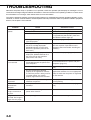
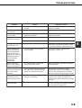
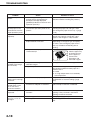
TROUBLESHOOTING . . . . . . . . . . . . . . . . . . . . .
4-6
4-7
4-8
USER MAINTENANCE . . . . . . . . . . . . . . . . . . . . 4-11
● Cleaning the scanner module . . . . . . . . . . . . . 4-11
●
●
●
●
●
●
●
Specifications . . . . . . . . . . . . . . . . . . . . . . . . . 5-17
Saddle stitch finisher functions . . . . . . . . . . . . 5-18
Using the saddle stitch finisher . . . . . . . . . . . .
Staple cartridge replacement and
staple jam removal . . . . . . . . . . . . . . . . . . . . .
Misfeed in the saddle stitch finisher . . . . . . . .
Troubleshooting
(concerning the saddle stitch finisher) . . . . . .
Stapling position quick reference guide for
duplex output . . . . . . . . . . . . . . . . . . . . . . . . .
Relation between print image and
saddle stitch . . . . . . . . . . . . . . . . . . . . . . . . . .
5-20
5-21
5-24
5-26
5-27
5-28
CHAPTER 5
PERIPHERAL DEVICES
CHAPTER 6
KEY OPERATOR PROGRAMS
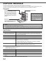
DUPLEX MODULE . . . . . . . . . . . . . . . . . . . . . . . . 5-2
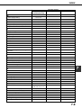
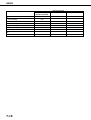
KEY OPERATOR PROGRAMS . . . . . . . . . . . . . . 6-2
● Key operator program list . . . . . . . . . . . . . . . . . 6-2
●
●
●
●
●
●
Part names . . . . . . . . . . . . . . . . . . . . . . . . . . . . 5-2
Specifications . . . . . . . . . . . . . . . . . . . . . . . . . . 5-2
Loading paper in the bypass tray . . . . . . . . . . . 5-3
Setting the printer driver for duplex module,
bypass tray and exit tray . . . . . . . . . . . . . . . . . . 5-4
Copying in the duplex mode . . . . . . . . . . . . . . . 5-4
Troubleshooting (concerning the duplex module) 5-5
●
●
Using the key operator programs . . . . . . . . . . . 6-3
Description of setting programs . . . . . . . . . . . . 6-7
CHAPTER 7
APPENDIX
MAIL-BIN STACKER . . . . . . . . . . . . . . . . . . . . . . . 5-6
● Part names . . . . . . . . . . . . . . . . . . . . . . . . . . . . 5-6
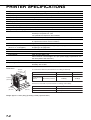
PRINTER SPECIFICATIONS . . . . . . . . . . . . . . . . 7-2
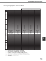
● List of principal printer driver functions . . . . . . . 7-3
●
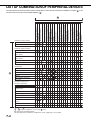
LIST OF COMBINATION OF
PERIPHERAL DEVICES . . . . . . . . . . . . . . . . . . . 7-4
NOTICE PAGE PRINTING . . . . . . . . . . . . . . . . . . 7-5
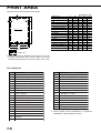
PRINT AREA . . . . . . . . . . . . . . . . . . . . . . . . . . . . 7-6
●
●
●
Specifications . . . . . . . . . . . . . . . . . . . . . . . . . . 5-6
Specifying mail bins to receive printed output . . 5-7
Setting in the printer driver . . . . . . . . . . . . . . . . 5-7
Misfeed in the mail-bin stacker . . . . . . . . . . . . . 5-8
FINISHER . . . . . . . . . . . . . . . . . . . . . . . . . . . . . . . 5-9
● Part names . . . . . . . . . . . . . . . . . . . . . . . . . . . . 5-9
●
●
●
●
●
●
●
Specifications . . . . . . . . . . . . . . . . . . . . . . . . . . 5-9
Finisher functions . . . . . . . . . . . . . . . . . . . . . . 5-10
Using the finisher functions . . . . . . . . . . . . . . . 5-11
Staple cartridge replacement . . . . . . . . . . . . . 5-12
Misfeed in the finisher . . . . . . . . . . . . . . . . . . . 5-14
Troubleshooting finisher problems . . . . . . . . . 5-15
Stapling position quick reference guide for
duplex output . . . . . . . . . . . . . . . . . . . . . . . . . 5-16
0-8
INDEX . . . . . . . . . . . . . . . . . . . . . . . . . . . . . . . . . . 7-7
KEY OPERATOR CODE NUMBER . . . . . . . . . . 7-11
CHAPTER 1
BEFORE USING THE PRODUCT
This chapter describes basic information that should be read before using
this product.
Page
INTRODUCTION ......................................................................................
MAIN FEATURES ....................................................................................
PART NAMES AND FUNCTIONS ...........................................................
● Exterior ...............................................................................................
● Interior ................................................................................................
● Part names and functions of peripheral devices ...............................
● Operation panel of the main unit .......................................................
● Operation panel of the scanner module ............................................
● Touch panel (on the scanner module) ..............................................
LOADING PAPER ....................................................................................
● Loading paper in paper tray 1 ...........................................................
● Changing the paper size in paper tray 1 ...........................................
● Specifications of paper trays .............................................................
● Setting the paper size and type .........................................................
● Loading paper in the multi purpose drawer ......................................
● Specifications (multi purpose drawer) ...............................................
● Loading paper in the stand/3 x 500 sheet paper drawer ..................
● Specifications (stand/3 x 500 sheet paper drawer) ..........................
● Loading paper in the stand/MPD & 2000 sheet paper drawer .........
● Specifications (stand/MPD & 2000 sheet paper drawer) ..................
ADDING TONER ......................................................................................
STORAGE OF SUPPLIES .......................................................................
1-2
1-3
1-4
1-4
1-5
1-6
1-9
1-12
1-13
1-16
1-16
1-16
1-17
1-19
1-21
1-23
1-23
1-23
1-24
1-24
1-25
1-25
1-1
INTRODUCTION
To gain the maximum benefits in using this product, it is recommended that the user read this manual to become
familiar with all the features and functions of the basic product and the precautionary information contained in the
manual.
NOTE
In this manual, American spellings are used.
This product is a high speed laser printer that can be extended to become multifunctional through the installation of
optional peripheral devices. The product can be extended to include copier, network scanning, facsimile or network
printing capabilities. This manual describes the basic use of the product as a printer and does not contain use information
for any of the optional peripheral devices. Separate operation manuals are included with each of the optional peripheral
devices. Refer to these manuals for their operation.
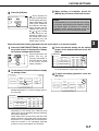
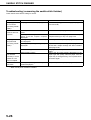
Original and paper sizes
This machine allows use of standard sizes in both the inch and AB systems.
The standard sizes available in this machine are shown below.
Sizes in the inch system
Sizes in the AB system
When the machine is being
operated from the operation
panel on the main unit:
When the machine is being
operated from the touch panel on
a scanner module:
LEDGER
11 x 17
A3
LEGAL
8-1/2 x 14
B4
FOOLSCAP
8-1/2 x 13
A4
LETTER
8-1/2 x 11
B5
EXECUTIVE
7-1/4 x 10-1/2
A5
INVOICE
5-1/2 x 8-1/2
In this manual, the indications for the scanner module touch panel as shown in the table above are used.
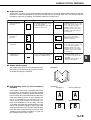
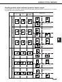
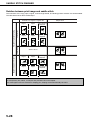
The meaning of “R” in original and paper size indications
Some original and paper sizes can be placed in either the portrait or landscape orientations. To differentiate between
landscape and portrait, the landscape orientation size indication will contain an “R”. These are indicated as 8-1/2 x 11R,
5-1/2 x 8-1/2R, A4R, B5R, etc. Sizes that can be placed only in the landscape orientation (11 x 17, 8-1/2 x 14, 8-1/2 x 13,
A3, B4) do not contain the “R” in their size indication.
Size indication with “R”
Landscape orientation
1-2
Size indication without “R”
Portrait orientation
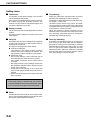
MAIN FEATURES
Laser printer able to accept a range of peripherals allowing it to be configured to specific needs
This product is a laser printer that can be used as a local printer which can be configured by the addition of
peripheral devices to extend its capabilities to include copier, network printer, network scanner or facsimile features.
A range of optional units to enhance productivity
Optional additions such as duplex units for producing two-sided output, additional paper feed units to increase the
variety of available paper sizes and paper capacity, paper output units to sort and otherwise organize the output
and a scanner module for automatically scanning documents.
600 dpi high resolution printing
High-definition and high quality printing with 600 dpi resolution can be performed. Also high image quality equivalent
to 1200 dpi can be output by using a smoothing function.
High speed monochrome printing
Depending upon the model chosen, high speed printing at 35 letter (A4) size pages/minute or 45 letter (A4) size
pages/minute is available.
PostScript compatible
Installation of a PS3 expansion kit gives PostScript compatibility (PostScript level 3).
Energy saving features
This product has the following two power reducing modes that conform to the
Energy Star guidelines which help to conserve natural resources and reduce
environmental pollution.
Preheat mode
The preheat mode is the first level of power reduction. The power is reduced
to the fuser unit a preset time after the machine has completed a job and no
further machine operations have been made. The machine can recover to
the ready condition within a short period of time. The preset time to enter
the mode can be set by a key operator program.
As an ENERGY STAR®
Partner, SHARP has
determined that this
product meets the
E NERGY
S TAR ®
guidelines for energy
efficiency.
Auto power shut-off mode
The auto power shut-off mode is the second level of power reduction. In this
mode power is shut off to the fusing unit and the touch panel. In this state
more energy is saved than in the preheat mode but the time to recover to
the ready condition will be longer. The preset time to enter this mode can be
set by a key operator program.
When this product is used as a printer, and either of the above modes is active, the mode will be deactivated
automatically by an incoming job and the machine will automatically warm up and start to print when it has
reached the ready temperature.
When this product is configured for multi-function operation, and either of the above modes is active, the mode
will be deactivated as above by either an incoming print job or received facsimile data. Either mode will also be
deactivated by any key operation on the operation panel or by the action of an original being placed for copying
or facsimile transmission.
1-3
1
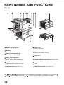
PART NAMES AND FUNCTIONS
Exterior
Bypass tray paper guide
Front cover
Open to add toner .
Exit tray*
Duplex module/bypass tray*
Module for two-sided printing
Main switch
Press to turn power on and off.
Paper tray 1
*
Upper paper output area
Finished sheets are deposited here.
Stand/3 x 500 sheet paper drawer* (See page 1-23.)
Upper exit tray extension*
Provides support for large size paper.
Stand/MPD & 2000 sheet paper drawer* (See page
1-24.)
Operation panel (See page 1-9.)
Multi purpose drawer* (See page 1-21.)
, , , , , and
are peripheral devices. For description of these devices, see page 1-7. One of devices
, and
must be installed. If you install
or , a power supply unit (page 1-8) must also be installed.
1-4
,
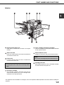
PART NAMES AND FUNCTIONS
Interior
1
Duplex module side cover
Open when a misfeed has occurred in the duplex
module.
Toner cartridge (drum/toner cartridge)*
The toner cartridge must be replaced when indicated
on the operation panel.
Side cover latch
Push up to open the side cover when a misfeed has
occurred in the main unit.
Photoconductive drum
Images are formed on the photoconductive drum.
Fusing unit
Lift up to open the side cover when a misfeed has
occurred in the main unit.
CAUTION
The fusing unit is hot. Take care in removing misfed
paper.
NOTE
Do not touch or damage the photoconductive drum.
Cartridge lock lever
When replacing the drum, toner or developer cartridge,
turn down this lever and pull it out.
Developer cartridge*
This cartridge contains developer and must be
removed and replaced by a new cartridge when
indicated on the operation panel.
* For replacement and installation of cartridges, refer to the Operation Manual (Read this document before installing the
product.).
1-5
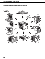
PART NAMES AND FUNCTIONS
Part names and functions of peripheral devices
1-6
PART NAMES AND FUNCTIONS
B/W scanner module/DSPF (AR-EF1)
The B/W scanner module/DSPF is a monochrome
scanner that uses two scanning modes. In one mode,
sheet originals are fed and scanned by the action of
the moving originals. In this mode either one side of
an original can be scanned or both sides of an
original can be scanned at the same time. The other
mode of scanning uses a moving mirror for scanning
originals placed on the glass platen.
Upper exit tray extension (AR-TE4)
Mount this unit to the upper paper exit tray. This
extension is needed to support large size paper.
Finisher (AR-FN6)
Output sheets can either be sorted in page order or
grouped by page. Sorted sets or groups are offset
stacked for easy separation when removed. Sorted
sets can be delivered either stapled or unstapled.
Mail-bin stacker (AR-MS1)
This unit is an output sorter that has seven receiving
bins.
The bin to receive printed output can be selected in
the printer driver. Each bin can be assigned to receive
printed output by an individual person or by groups
of people so that their prints are separated from other
users making them easy to retrieve.
When this unit is installed, any copies or facsimile
prints will be sent to the top tray and not into the
mail bins.
Multi purpose drawer (AR-MU1)
Up to 500 sheets of 20 lbs. (80 g/m2) paper can be
loaded. Also special papers such as envelopes
(standard sizes only) and postcards can be set.
Stand/3 x 500 sheet paper drawer (AR-D14)
This paper feed unit contains an upper multi-purpose
drawer (see item ) and two lower drawers each of
which can hold a maximum of 500 sheets of 20 lbs.
(80 g/m2) paper.
Saddle stitch finisher (AR-FN7)
The saddle stitch finisher can automatically place
two staples for centerline binding of prints or copies
and fold them along the centerline.
An optional hole punching unit is available for
installation into the finisher.
Duplex module (AR-DU3)
An optional duplex module must be installed for
automatic two-sided printing.
Duplex module/bypass tray (AR-DU4)
This module is basically the same as
above with
the addition of a manual bypass paper feed unit.
Exit tray (AR-TE3)
Mounted to the paper output port of a duplex module.
Stand/MPD & 2000 sheet paper drawer (AR-D13)
This paper feed unit contains an upper multi-purpose
drawer (see item ) and a lower drawer which can
hold a maximum of 2000 sheets of 20 lbs. (80 g/m2)
paper.
Some peripheral devices cannot be installed together while others may require the installation of one or more others to
be functional. See page 7-4, “LIST OF COMBINATION OF PERIPHERAL DEVICES.”
Peripheral devices are basically optional, but some are provided as standard equipment for some models.
1-7
1
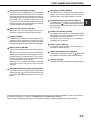
PART NAMES AND FUNCTIONS
■ Other optional equipment
●
Scanner rack (AR-RK1)
This rack is required to support the scanner module
above the printer.
●
Power supply unit (AR-DC1)
Some peripheral devices require the installation of
this power supply.
●
●
●
Print server card (AR-NC5J)
A NIC (network interface card) is necessary for
connecting the printer to a network.
Multi-function controller board (AR-M11)
This print controller is necessary to provide copier,
facsimile and network scanning capabilities.
PS3 expansion kit (AR-PK1)
This kit provides compatibility of PostScript level 3
to the printer.
1-8
●
Hard disk drive (AR-HD3)
Extends the image storing capacity for the printer
and copier features. This unit is required for the job
retention function (see page 2-9) to operate.
●
Facsimile expansion kit (AR-FX5)
This kit is required to add facsimile features.
●
Additional fax memory (8 MB) (AR-MM9)
●
Network scanner expansion kit (AR-NS2)
This kit is required to add the network scanning
feature.
●
Printer kit (AR-P14)
The Printer Kit is required to upgrade a product whose
model name contains suffix "U" (ex. AR-M280U) to
network printer. To use such model as network printer,
the Printer Kit and Printer Server Card (AR-NC5J)
are required.
PART NAMES AND FUNCTIONS
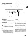
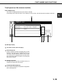
Operation panel of the main unit
The display and indicators show the current status of the printer. All printer settings are made by using the keys and
display panel.
1
Message display
Displays the current status of the printer.
[ i ] displayed in any message indicates that the
[INFORMATION] key should be pressed.
[ERROR] indicator
Lights up when paper or toner must be added or when
a misfeed has occurred in the machine. Blinks when
an abnormal condition has occurred in the machine.
[DATA] indicator
Lights up or blinks when print data is being received
or output. Also lights up when job data is stored by
the job retention function (page 2-9).
[READY] indicator
Print data can be received when this indicator is lit.
[MENU] key
Press to select a menu group such as printer
configuration menu (page 3-2), custom settings
(page 3-6) or execution of print jobs held by the
retention function (page 2-9). Also, press to return
to the job status screen from the setting screen of
each job status group.
[ / ] keys
Press to select menu or function items or to set
numerical values for those items.
[BACK/C] key
Use this key to return to the previous screen in each
menu selection, to cancel and delete the current job
or to delete a reserved job that has been selected.
[OK] key
Press to register the selected menu or function.
[INFORMATION] key
When [ i ] is displayed with a message indicating a
paper misfeed, the relevant operation procedure can
be displayed by pressing the [INFORMATION] key.
If the [INFORMATION] key or the [BACK/C] key is
pressed while the operation procedure is displayed,
the information mode will be canceled. If you press
and hold down this key while printing is being
performed or in standby, the total number of printed
pages and quantity of toner remaining (as a
percentage) will be displayed.
1-9
PART NAMES AND FUNCTIONS
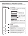
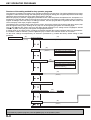
Menu group and explanation of the use of the keys on the main unit operation panel
The menu groups are classified into five groups and are selected consecutively by pressing the [MENU] key. If the
[OK] key is pressed when the desired menu screen is displayed, a message will appear to indicate the next required
operation.
Job status screen
READY.
[MENU] key
The message "WARMING UP" will be displayed when the power is turned on
and a list of the current job plus reserved jobs or a list of completed jobs will
be displayed on the job status screen. Examples of the various messages
which will be displayed are shown below.
(Display example)
WARMING UP.
The printer is warming up.
READY.
The printer is ready to print.
FROM TRAY #
The printer is currently printing.
CHANGE THE TONER
CARTRIDGE.
PAPER JAM.
ADD PAPER.*
Out of toner. Replace the toner
cartridge. See the separate
operation
manual
entitled
"Operation Manual (Read this
document before installing the
product.)".
A misfeed has occurred. (See
page 4-2.)
Out of paper. Load paper. (See
page 1-16.)
* [ADD PAPER]
When the status display shows [ADD PAPER], paper is required to
complete a job in progress. In this case, printing of the job will be
suspended until the required paper is added or another paper is
selected (see "Setting the paper size and type" on page 1-19).
While a current job is suspended, the printer will print a reserved
job if paper is available from another source for that job but will not
print any other jobs.
PRINT JOBS ON HOLD
[MENU] key
SET OPERATIONS
CONDITIONS
[MENU] key
CUSTOM SETTINGS
[MENU] key
KEY OPERATOR
PROGRAMS
If the job retention function is used from your computer, print data will
be stored in the printer as a hold job.
The job retention function can be used only if the printer is equipped
with a hard disk drive unit. (See page 2-9.)
Condition settings
The printer condition settings are used for basic printer settings. (See
page 3-2.)
Custom settings
Custom settings are used to make settings based on use patterns.
(See page 3-6.)
Key operator programs
[MENU] key
1-10
Print hold
These are settings used by key operators (administrators of this
product). For the use of these programs, see page 6-1.
PART NAMES AND FUNCTIONS
Canceling a print job and deleting print data
●
To cancel a print job in progress and delete the print data:
Press the [BACK/C] key during printing. Printing will stop and a message asking for confirmation to delete the job
will appear. To delete the data, press the [OK] key.
To cancel deletion, press the [BACK/C] key. Printing will resume.
●
To delete print data of a reserved job (jobs stored in the printer):
Print data transmitted from computers will be stored in this printer (up to 99 jobs) and will be printed sequentially. To
delete print data of a reserved job before starting printing, press the [ ] or [ ] key to display the desired data in the
message display. If you press the [BACK/C] key at this time, a confirmation message for deletion will appear. To
delete the data, press the [OK] key.
To cancel deletion, press the [BACK/C] key. Printing will resume.
1-11
1
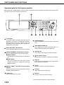
PART NAMES AND FUNCTIONS
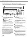
Operation panel of the scanner module
When the printer is equipped with a scanner module, the operation panel on the main unit will become inoperative and
the panel on the scanner module must be used.
Touch panel
The machine status, messages and touch keys are
displayed on the panel. The display will change to
show the status of print, copy, network scan or fax
according to which of those modes is selected. For
details see the next page.
Mode select keys and indicators
Use to switch the display mode of the touch panel.
[PRINT] key/READY indicator/DATA indicator
Press to enter the print mode. (See next page.)
●
READY indicator
Print data can be received when this indicator is
lit.
● DATA indicator
Lights up or blinks when print data is being
received. Also lights up or blinks when printing is
being performed.
[IMAGE SEND] key/LINE indicator/DATA
indicator
Press to enter the network scan/fax mode. (See the
facsimile operation manual.)
[COPY] key
Press to select the copy mode.*
[JOB STATUS] key
Press to display the current job status. (See page
1-14.)
[CUSTOM SETTINGS] key
Use to adjust the contrast of the touch panel or to
set key operator programs. (See page 3-6.)
Numeric keys
Use to enter number values for various settings.
[ ] key ([ACC.#-C] key)
Use for account control for copying and fax sending.
[#/P] key*
This key is used as a program key for copy features
and in dialing for fax features.
[C] key*
This key is active for copy and fax features.
Start key*
Use to start copying and fax jobs.
[CA] key*
Functions in the copy and fax modes.
* See the operation manual for copier operation.
1-12
PART NAMES AND FUNCTIONS
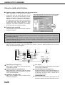
Touch panel (on the scanner module)
Print mode screen
This screen is displayed when the print mode is selected.
(The display varies with the mode. For the display in other modes, see their respective operation manuals.)
1
SELECT JOB.
PRINT HOLD JOB LIST
Sharp 005
Microsoft Word - Test001
Sharp 006
1/1
EXCEL1
CONDITION
SETTINGS
Message display
Job status screen (See next page.)
Print hold job list
If the job retention function (see page 2-9) is used,
the list of stored print jobs is displayed here (up to
100 jobs). The job retention function can be used
only if the printer is equipped with a hard disk drive
unit. If the main switch is turned off, stored print
data will be cleared.
Display scroll keys
Use these keys to view the job hold list when it is
contained on more than one screen.
[CONDITION SETTINGS] key
Use to switch the display to the printer configuration
menu (see page 3-2).
1-13
PART NAMES AND FUNCTIONS
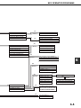
Job status screen (common to print, copy, network scan, and fax modes)
This screen is displayed when the [JOB STATUS] key on the operation panel is pressed.
A job list showing the current job at the top of the job queue or a list showing completed jobs can be displayed. The
contents of the jobs can be viewed, moved up to the highest priority in the job queue or deleted from the queue.
JOB QUEUE
COPY
SETS / PROGRESS
003 / 000
JOB QUEUE
STATUS
COPYING
1/1
SHARP001
003 / 000
PAPER EMPTY*
054234
010 / 000
WAITING
COMPLETE
DETAIL
PRIORITY
STOP/DELETE
PRINT JOB
E-MAIL/FTP
Job list
A job list which indicates the current job and reserved
jobs or a job list which indicates completed jobs is
displayed. The icons to the left of the jobs in queue
represent the job mode.
Print mode
Copy mode
Network scan mode
Fax mode
(transmission job)
Fax mode
(reception job)
When a job list which indicates the current job and
reserved jobs is displayed, the displayed jobs
themselves are operation keys. To cancel printing
or to give a job the highest print priority, touch the
relevant job key to select the job and execute the
desired operation using the keys described in ,
, and .
* “PAPER EMPTY” in the job status display
When a job status display indicates “PAPER EMPTY”,
the specified size paper is not loaded in any tray to run
that job.
In this case, printing is suspended for that job until the
required paper is loaded.
Until the required paper is loaded another reserved job
data will be printed if possible.
(If paper runs out during printing, another job will not be
printed.) If you wish to change the paper size because
you do not have the specified size paper, you can
change the size by touching the current job key to select
it and touch the [DETAIL] key described in .
1-14
FAX JOB
Mode switching key
Use to switch the job list between “JOB QUEUE”
and “COMPLETE”.
“JOB QUEUE”: Displays the list of the current job
and the reserved jobs.
“COMPLETE”: Displays the list of completed jobs.
[PRINT JOB] key
Use to display the print job list for all modes (print,
copy, network scan, and fax).
[E-MAIL/FTP] key
Use to display the list of jobs that use the network
for sending e-mail by SNMP protocol or sending to
an ftp site or desktop by ftp protocol.
[FAX JOB] key
Use to display the fax communication status and
the reserved transmission job status.
Display switching keys
Use to switch the page of the displayed job list.
[STOP/DELETE] key
Use to cancel or delete the current job or delete the
selected reserved job. Received fax print jobs that
have been reserved, however, cannot be deleted.
[PRIORITY] key
If you select a job among the reserved jobs in the
“JOB QUEUE” job list to which you wish to give the
highest priority and touch this key, the job will move
to the highest priority reserved job.
[DETAIL] key
Use to display the detailed information of the selected
job. The paper size for printing can be changed from
the specified size.This function, however, cannot be
used when a fax reception print job is selected.
PART NAMES AND FUNCTIONS
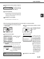
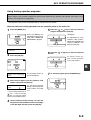
Using the touch panel
■ How to use the touch panel
[Example 1]
[Example 1]
JOB QUEUE
COPY
SHARP001
054234
Items on the touch panel
are easily selectable by
touching the key associ003 / 00 ated with the item with a
finger. Selection of an
010 / 00
item will be accompanied
Beep
with a beep tone to
tone
confirm the item was
selected. Also, the key
area for the item will be
highlighted for visual
confirmation.
SETS / PR
003 / 00
[Example 2]
1/13
■ Selection of function
COMPLETE
Keys which are grayed
out on any screen are not
selectable. If a grayed out
key is touched, a double
beep will be sounded.
OK
010 / 000
WAITING
1. 812 11
PLAIN
2. 812 11
TRANSPARENCY
3. 11 17
PLAIN
PAPER SELECT
Items which are highlighted at the time a screen
appears are already selected and will be registered
to function if the [OK] key is touched.
[Example 2]
DUAL PAGE
COPY
MULTI SHOT
The confirmation beeps can be disabled by a key
operator program. (See page 6-9.)
Copier feature
Dual page copy
Job build
When the machine is
used in the copy or fax
modes, the functions
shown below can only be
set on the special feature
screen. They can be set
or cancelled by alternate
touches on the panel.
Facsimile feature
Polling
Dual page scan
[Example 3]
READY TO SCAN FOR COPY.
SPECIAL MODES
2-SIDED COPY
OUTPUT
READY TO SEND.
AUTO
EXPOSURE
STANDARD
RESOLUTION
PROGRAMMED
FILE FORMAT
AUTO
ORIGINAL
When the machine is
used in the copy or fax
modes and a special
feature is selected, a
corresponding
icon
representing the feature
will appear on the touch
key and on the main
screen of the mode
selected. If this icon is
touched, the setting
screen of the function (or
a menu screen) will
appear, allowing the
settings to be checked or
adjusted and the function
to be canceled easily.
1-15
1
LOADING PAPER
The message “ADD PAPER” or “OPEN TRAY
Follow the procedure below to load paper.
AND ADD PAPER” will appear when paper runs out during operation.
NOTES
● Do not use curled or folded paper. Doing so may cause a misfeed.
● For best results use paper supplied by SHARP. (See page 1-18.)
● When you change the paper type and size in paper tray 1, set the paper type and size referring to “Setting the
paper size and type” (page 1-19).
● Do not place heavy objects or press hard on any tray which is pulled out.
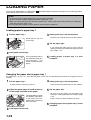
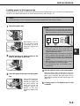
Loading paper in paper tray 1
1 Pull out paper tray 1.
3 Gently push tray 1 into the machine.
Gently pull the tray out
until it stops.
Push the tray firmly all the way into the machine.
4 Set the paper type.
If you change the paper type, be sure to set the
paper type referring to “Setting the paper size and
type” (page 1-19).
2 Load paper into the tray.
Do not load paper above
the maximum height line
(approximately
500
sheets of 20 lbs. (80 g/m2)
paper).
paper in paper tray 1 is now
5 Loading
complete.
Changing the paper size in paper tray 1
For paper tray 1, 8-1/2" x 11", A4 or B5 size paper can be set. Use the following procedure to change the size as
needed.
1 Pull out paper tray 1.
4 Gently push tray 1 into the machine.
If paper remains in the tray, remove it.
the guide plates A and B in the tray
2 Adjust
to the length and width of the paper.
The guide plates A and B
are slidable. Adjust them
to the paper size to be
loaded while squeezing
their lock levers.
3 Load paper into the tray.
1-16
Push the tray firmly all the way into the machine.
5 Set the paper size.
Be sure to set the paper size and paper type
referring to “Setting the paper size and type” (page
1-19).
If this is not done, paper misfeeds will occur.
paper size in paper tray 1 is now
6 Changing
complete.
LOADING PAPER
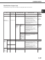
Specifications of paper trays
The specifications for types and sizes of paper for loading paper trays are shown below.
Tray
Paper tray 1
Multi purpose
drawer/bypass tray
Tray No.
(tray name)
Tray 1
Applicable paper types
Plain paper (Refer to the next
page for applicable plain papers.)
●
Plain paper (Refer to the next
page for applicable plain papers.)
●
●
●
Tray 2/bypass tray
Special paper
(Refer to the
next page for
applicable
special
papers.)
●
Thick paper
Labels,
transparency
film
If "AUTO-INCH" is selected in setting the
paper size and type (page 1-19), the
following paper sizes can be used with the
automatic detection function:
8-1/2 x 11, 8-1/2 x 11R
● If "AUTO-AB" is selected in setting the
paper size and type (page 1-19), the
following paper sizes can be used with the
automatic detection function:
A4, A4R, B5, B5R
● Non-standard sizes smaller than 8-1/2 x 11
or A4
●
Envelopes can
only be fed from
the multi-purpose
drawer.
Applicable paper
stock weight for
envelopes is 20
to 23 lbs. or 75 to
90 g/m2.
●
Tray 2
Same as multi purpose drawer
Tray 3
Plain paper (Refer to the next
page for applicable plain papers.)
Lower
Tray 4
Upper
Tray 2
Same as multi purpose drawer
Lower
Tray 3
Plain paper (Refer to the next
page for applicable plain papers.)
8-1/2 x 11, A4, B5
16 to 28 lbs.
or 60 to 105
g/m2
If "AUTO-INCH" is selected in setting the
paper size and type (page 1-19), the
following paper sizes can be used with the
automatic detection function:
16 to 34 lbs.
11 x 17, 8-1/2 x 14, 8-1/2 x 11, 8-1/2 x 11R,
or 60 to 128
7-1/4 x 10-1/2R, 5-1/2 x 8-1/2R
g/m2
● If "AUTO-AB" is selected in setting the
paper size and type (page 1-19), the
following paper sizes can be used with the
automatic detection function:
A3, B4, A4, A4R, B5, B5R, A5R, 8-1/2 x 13
● Non-standard sizes
Postcard
Stand/3 x Upper
500 sheet
Middle
paper
drawer
Stand/
MPD &
2000
sheet
paper
drawer
Applicable paper sizes
Paper
weight
See the
remarks for
special paper
on the next
page.
Japanese official postcard
Applicable standard size envelopes:
COM-10, Monarch, DL, C5, ISO B5
● Non-standard size
16 to 28 lbs.
If "AUTO-INCH" is selected in setting the
or 60 to 105
paper size and type (page 1-19), the
following paper sizes can be used with the g/m2
automatic detection function:
11 x 17, 8-1/2 x 14, 8-1/2 x 11, 8-1/2 x 11R,
7-1/4 x 10-1/2R
● If "AUTO-AB" is selected in setting the
paper size and type (page 1-19), the
following paper sizes can be used with the
automatic detection function:
A3, B4, A4, A4R, B5, B5R, 8-1/2 x 13
●
●
8-1/2 x 11, A4
16 to 28 lbs.
or 60 to 105
g/m2
1-17
1
LOADING PAPER
■ Applicable plain paper
For satisfactory results, plain paper must conform to the following requirements.
Paper in AB system
Paper in inch system
A5 to A3
5-1/2 x 8-1/2 to 11 x 17
16 to 28 lbs. or 60 to 105 g/m2
Plain paper
Recycled, colored, pre-punched, pre-printed and letterhead papers must conform to the same conditions as above.
■ Applicable special paper
For satisfactory results, special paper must conform to the following requirements.
Special paper
1-18
Type
Remarks
Thick paper
●
Transparency film, labels,
and tracing paper
●
Use SHARP recommended paper. Do not use labels other
than SHARP recommended labels. Doing so may leave
adhesive residue in the printer, causing paper misfeeds,
smudges on prints or other machine trouble.
Postcards
●
Japanese official postcards can be used.
Envelopes
●
For 5-1/2 x 8-1/2 to 8-1/2 x 11 or A5 to A4 sizes, thick
paper ranging from 16 to 34 lbs. or 60 to 128 g/m2 can be
used.
● For sizes larger than 8-1/2 x 11 or A4, thick paper ranging
from 16 to 28 lbs. or 60 to 105 g/m2 can be used.
● Other thick papers
Index stock (65 lbs. or 176 g/m2) can be used.
Cover stock (110 lbs. or 200 to 205 g/m2) can be used but
only for 8-1/2 x 11, A4 paper in the portrait orientation.
● For 5-1/2 x 8-1/2 or A5 paper, the orientation must be
landscape.
Applicable standard envelopes: COM-10, Monarch, DL, C5,
ISO B5
● Envelopes can only be fed from the multi-purpose drawer.
Applicable paper stock weight for envelopes is 20 to 23
lbs. or 75 to 90 g/m2.
LOADING PAPER
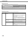
Setting the paper size and type
For the specifications for types and sizes of paper for loading paper trays, see page 1-17.
Setting the paper size and type from the operation panel on the main printer
When the paper size or type is changed in a paper tray, set them referring to the following procedure.
the [MENU] key repeatedly until
1 Press
“CUSTOM SETTINGS” appears in the
the [OK] key.
7 Press
To cancel the setting change, press the [BACK/C]
key to return to step 4.
message display.
the paper type that has been set in
8 Select
the tray.
PLAIN
OK?
2
Press the
or
key
repeatedly until the paper
type that has been set
appears.
NOTE
Press the [OK] key.
When the [OK] key is
pressed,“TRAY SETTING”
will appear in the message
display.
Special paper such as thick paper, transparency film,
labels, and postcards can be set for tray 2 and the bypass
tray.
Envelopes can be set only for tray 2.
9 Press the [OK] key.
3 Press the [OK] key.
TRAY SETTING
TRAY1
4
When the [OK] key is
pressed,the message
shown to the left will
appear in the message
display.
Select the desired paper tray.
Press the
or
key
repeatedly until the
desired paper tray is
indicated in the display.
5 Press the [OK] key.
The paper size and paper type of the tray selected
in step 4 will appear.
If TRAY 1 is selected in
LETTER
step 4, the message
PLAIN
shown to the left will
appear in the display.
6 Press the
CHANGE TRAY1
SETTING OK?
that the desired paper size is
10 Ensure
selected.
LETTER
OK?
Press the key or key
repeatedly until the
desired paper size
appears.
Depending on the selected tray, a selection for
“AUTO-AB” and “AUTO-INCH” may appear.
“AUTO-AB”: Select when you have set AB system
paper.
“AUTO-INCH”: Select when you have set inch
system paper.
When the paper system is changed from the inch
system to the AB system or vise versa, the paper
type must be designated. Select the paper type.
● If you have set paper of non-standard size, select
“NON STANDARD”. This size can be selected
when tray 2 or the bypass tray has been selected
in step 4.
●
11 Press the [OK] key to complete the setting.
key.
If TRAY 1 is selected in
step 4, the message
shown to the left will
appear in the display.
1-19
1
LOADING PAPER
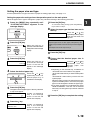
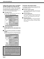
Setting the paper type and size from the touch panel
1 Press the [CUSTOM SETTINGS] key.
The custom setting menu
screen will appear.
2 Press the [TRAY SETTINGS] key.
TOTAL COUNT
“AUTO-INCH”: Select when you have set inch
system paper.
When the paper system is changed from the inch
system to the AB system or vise versa, the paper
type must be designated. Select the paper type.
● If you have set paper of non-standard size, select
“NON STANDARD SIZE”. This size key appears
when tray 2 or the bypass tray has been selected
in step 3.
5 Touch the [OK] key to complete the setting.
The paper tray selection
screen will appear.
OK
SIZE
TRAY SETTINGS
A4
the paper tray for which the setting
3 Select
is to be made.
TYPE / SIZE
TRAY 1
PLAIN / 81/2X11
TRAY 2
PLAIN / AUTO-INCH
TRAY 3
RECYCLED / AUTO-INCH
4
●
If the desired tray is not
on the display, use [ ] or
[
] key to scroll the
display until it appears.
Select the paper type and the paper size.
If TRAY 1 has been selected in step 3:
CUSTOM SETTINGS
TRAY 1 TYPE/SIZE SETTING
OK
TYPE
SIZE
PLAIN
LETTER HEAD
812 11
PRE-PRINTED
PRE-PUNCHED
B5
RECYCLED
COLOR
A4
The highlighted keys indicate the current selections.
To change either type or size or both, touch the
desired keys to highlight the selections.
Paper types
Special papers such as transparency film and
labels can be set for tray 2 and the bypass tray.
Envelopes can be set only for tray 2.
Paper sizes
● Depending on the selected tray, a selection for
“AUTO-AB” and “AUTO-INCH” may appear.
“AUTO-AB”: Select when you have set AB system
paper.
1-20
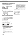
LOADING PAPER
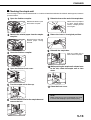
Loading paper in the multi purpose drawer
The method of loading paper into the multipurpose drawer is the same as for paper tray 1 described on page 1-16.
For specifications of paper, see page 1-17. When loading envelopes, postcards or transparency film, follow the
descriptions below.
● Two maximum height lines are indicated: one for plain paper and one for special paper.
1
Maximum height line for plain paper
Do not exceed this line when loading plain paper.
Maximum height line for special paper (red line)
Do not exceed this line when loading special paper.
■ How to change the paper size
To change the paper size or paper type when paper is loaded into a tray, refer to page 1-19 for details.
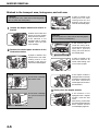
■ Setting envelopes or postcards
When setting envelopes or postcards in the multi purpose drawer, set them in the orientation shown below.
Loading postcards
Load postcards print side up to the rear left of the tray
as shown.
Loading envelopes
Envelopes can only be printed on the address side. Be
sure to place envelopes with the address side up and
the top of the envelope to the rear.
Printing onto envelopes or postcards
Attempting to print onto both sides of envelopes or postcards may result in misfeeds or poor prints.
Do not use pre-printed envelopes.
● To avoid wrinkling, misfeeds or poor printing, make sure the postcard stock is not curled.
●
●
1-21
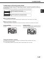
LOADING PAPER
Printing onto envelopes
●
Do not use envelopes that have metal clasps, plastic snaps, string closures, windows, linings, self-adhesive patches
or synthetic materials. Attempting to print on these may cause misfeeds, inadequate toner adherence or other
trouble.
● Envelopes of which the surface is not flat because of embossing may cause the prints to become smudges.
● Under high humidity and temperature conditions the glue flaps on some envelopes may become sticky and be sealed
closed when printed.
● Use only envelopes which are flat and crisply folded. Curled or poorly formed envelopes may be poorly printed or may
cause misfeeds.
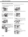
Fusing unit pressure adjusting levers
When feeding envelopes from the multi purpose drawer, damage to the envelopes or smudges on prints may occur
even if envelopes within specification are used. In this case, the problem may be reduced by shifting the fusing unit
pressure adjusting levers from the normal position to the lower pressure position. Follow the procedure below.
NOTE
Be sure to return the lever to the normal position when finished feeding envelopes. If not, inadequate toner adherence,
paper misfeeds or other trouble may occur.
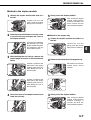
the duplex module and slide it to
1 Unlatch
the left.
Unlatch the module and
gently move the module
away from the machine.
If the machine is not
equipped with a duplex
module, open the side
cover similarly.
the two fusing unit pressure
2 Lower
adjusting levers marked A and B in the
illustration.
A
B
Normal position
Lower pressure position
A: Rear side of
fusing unit
1-22
B: Front side of
fusing unit
3
Gently close the duplex module.
If the machine is not
equipped with a duplex
module, close the side
cover.
LOADING PAPER
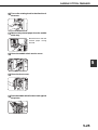
■ Loading transparency film
Be sure to load the transparency film with the white label side up. Make sure no image will be printed on the label.
Printing on the label may cause smudges on prints. Transparency film must be set in the portrait orientation.
1
Specifications (multi purpose drawer)
Name
Paper size/weight
Paper capacity
Dimensions
Weight
Multi purpose drawer
See specifications of paper trays on page 1-17.
500 sheets (20 lbs. (80 g/m2)) of paper, 40 envelopes, 20 postcards
25-3/4" (W) x 22-21/64" (D) x 5-43/64" (H)
(654 mm (W) x 567 mm (D) x 144 mm (H))
Approximately 24.3 lbs. or 11 kg
Specifications are subject to change for improvement without notice.
Loading paper in the stand/3 x 500 sheet paper drawer
Upper paper tray:
The upper tray is the same as the multi-purpose drawer. Use the upper tray according to the instructions for the multipurpose drawer on page 1-21.
Middle and lower paper trays:
Up to 500 sheets of SHARP recommended plain paper can be loaded in these trays. The method of loading paper is the
same as for paper tray 1 in the main unit. See the description (page 1-16).
NOTE
If the paper size or paper type is changed in either paper tray, the tray settings must be changed in custom settings. Refer
to “Setting the paper size and type” on page 1-19.
Specifications (stand/3 x 500 sheet paper drawer)
Name
Paper size/weight
Paper capacity
(ordinary paper)
Dimensions
Weight
Stand/3 x 500 sheet paper drawer
See specifications of paper trays on page 1-17.
500 sheets (20 lbs. (80 g/m2)) each
24-3/8" (W) x 26-5/32" (D) x 15-29/32" (H)
(619 mm (W) x 664 mm (D) x 404 mm (H))
Approximately 70.6 lbs. or 32 kg
Specifications are subject to change for improvement without notice.
1-23
LOADING PAPER
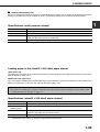
Loading paper in the stand/MPD & 2000 sheet paper drawer
Upper paper tray:
The upper paper tray is equivalent to the multi purpose drawer. The method of loading paper and the paper that can be
used are the same as for the multi purpose drawer. Refer to the description of the multi purpose drawer (see page 1-21).
Lower paper tray:
The lower paper tray is a large capacity tray that holds 2,000 sheets of 8-1/2" x 11" or A4 paper (20 lbs. (80 g/m2)). Use
the following procedure to load paper in the large capacity tray.
NOTE
If the paper size or paper type is changed in either paper tray, the tray settings must be changed in custom settings. Refer
to “Setting the paper size and type” on page 1-19.
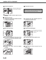
1 Pull out the large capacity tray.
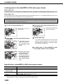
push the large capacity paper tray
3 Gently
into the printer.
Push the tray firmly all the
way into the printer.
Gently pull the tray out
until it stops.
paper onto the right and left paper
2 Load
feed tables.
●
Load paper onto the
right paper feed table.
The right table holds
approximately 1,200
sheets.
4
Set the paper type.
If you have changed the paper size from the AB
system to the inch system or vice versa, select
the relevant type referring to “Setting the paper
size and type” on page 1-19.
paper in the stand/MPD & 2000
5 Loading
sheet paper drawer is now complete.
●
Raise the paper guide
and load paper onto the
left paper feed table.
The left table holds approximately 800 sheets.
After loading paper, be
sure to return the paper
guide.
Specifications (stand/MPD & 2000 sheet paper drawer)
Name
Paper sizes/weight
Paper capacity
(ordinary paper)
Dimensions
Weight
Stand/MPD & 2000 sheet paper drawer
See specifications of paper trays on page 1-17.
Upper tray: 500 sheets (20 lbs. (80 g/m2)), Lower tray: 2,000 sheets (20 lbs. (80 g/m2))
24-3/8" (W) x 26-5/32" (D) x 15-29/32" (H)
(619 mm (W) x 664 mm (D) x 404 mm (H))
Approximately 75 lbs. or 34 kg
Specifications are subject to change for improvement without notice.
1-24
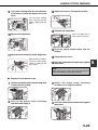
ADDING TONER
When toner runs out, the message “CHANGE THE TONER CARTRIDGE” will appear on the display indicating that the
toner cartridge must be replaced. For some models, a message to replace the developer cartridge may appear.
For the procedure for replacement of these cartridges, see the separate “Operation manual (Read this document before
installing the product.).”
NOTE
If you press and hold down the [INFORMATION] key or the [COPY] key while printing is being performed or in standby,
the quantity of toner remaining (as a percentage) will be displayed. When the percentage becomes 25 - 0 %, prepare
a new toner cartridge.
STORAGE OF SUPPLIES
Standard supplies for this product that are to be replaced by the user include paper, toner cartridge (drum/toner
cartridge), developer cartridge*, and staple cartridge for the finisher.
* For some models, developer cartridges are not replaced by users.
For best copying results, be sure to use only Sharp Genuine Supplies which are designed,
engineered, and tested to maximize the life and performance of Sharp products. Look for the
Genuine Supplies label on the toner package.
GENUINE SUPPLIES
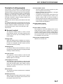
■ Proper storage
1 Store the supplies in a location that is:
clean and dry,
at a stable temperature,
not exposed to direct sunlight.
●
●
●
2 Store paper in the wrapper and lying flat.
Paper stored in packages standing up or out of
the wrapper may curl or become damp, resulting
in paper misfeeds.
●
1-25
1
1-26
CHAPTER 2
PRINTING FROM A COMPUTER
This chapter describes how to install and how to use the printer drivers
and printer utilities on a computer. This chapter also describes the job
retention function that allows a print start operation from the operation
panel of the printer.
Page
CONNECTING TO A COMPUTER ..........................................................
SOFTWARE FOR WINDOWS .................................................................
INSTALLING PRINTER DRIVERS AND PRINTER UTILITIES ..............
UNINSTALLING PRINTER DRIVERS AND PRINTER UTILITIES .........
INSTALLING PRINTER DRIVERS USING PLUG &
PLAY OR THE “ADD PRINTER WIZARD” ..............................................
● Before installation ..............................................................................
SETTING THE PRINTER DRIVER ..........................................................
● Printer driver settings under Windows
(selecting and setting print conditions) ..............................................
PRINTER CONFIGURATION THROUGH THE NETWORK ..................
● Environment required for accessing Web pages ..............................
● Accessing Web pages and displaying help ......................................
● Items and outline of menu frame of Web pages ...............................
JOB CONTROL ........................................................................................
● “JOB CONTROL” operation ...............................................................
● Hold job list .........................................................................................
● Printer account control .......................................................................
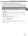
USING THE MACHINE AS A POSTSCRIPT PRINTER ...........................
● Using the printer in the Windows environment .................................
● Using the printer in the Macintosh environment ...............................
2-2
2-2
2-3
2-3
2-4
2-4
2-5
2-5
2-6
2-6
2-6
2-7
2-9
2-9
2-10
2-12
2-13
2-13
2-15
2-1
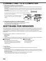
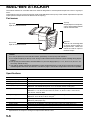
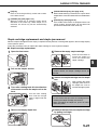
CONNECTING TO A COMPUTER
1. Using this machine as a local printer
When using this machine as a local printer, connect your computer to the parallel interface connector as shown in
the illustration.
The cable is not supplied with the printer. A shielded cable which conforms to both the printer specifications and
your computer specifications must be obtained. Consult your computer manual for the computer connection
requirements.
1
18
The parallel interface of the printer conforms to IEEE-STD-1284-1993.
36
19
The connector type on the printer is a 36-pin DDK 57LE-40360-730B (D29)
female connector or equivalent.
For the specifications of the parallel interface
connector on the computer, see the computer
manual.
Parallel interface connector
2. Using this machine as a network printer
For using this machine as a network printer, a print server card is needed.
See the operation manual supplied with the print server card.
For a network cable, use a shielded cable.
SOFTWARE FOR WINDOWS
When using this product in a Windows environment, you must install a printer driver in your computer system. Use the
CD-ROM supplied with this unit for the installation. This product can be connected through a parallel interface connector
as described above, or connected as a network printer through a print server card (network interface card).
The print server card may be installed as a standard component or an optional component depending upon the specific
printer model.
The following software for Windows is contained in the CD-ROM.
● Printer drivers
● Printer utilities
● Installer
This is software for installing the printer drivers and printer utilities. If you use Plug and Play or the “Add Printer
Wizard” to install the driver without using the installer, see instructions on page 2-4.
■ Printer drivers
PCL printer drivers (PCL5e and PCL6)
● Optional PostScript printer driver (compatible to
PostScript 3) and PPD files (PostScript Printer
Description files)
●
■ Printer utilities
Printer Administration Utility
Printer Status Monitor
● PCL Display Font
●
●
1. Printer drivers
Printer driver software converts print data from any application into data understood by the printer.
2. Printer utilities
Printer Administration Utility* provides setting and monitoring of printers on a computer. The Printer Status Monitor
provides monitoring of printer status, display and notification on a computer for network environment. (only in the
Windows environment)
For use of Printer Administration Utility and Printer Status Monitor, see the help file.
* Printer Administration Utility is software for system administrators.
2-2
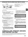
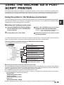
INSTALLING PRINTER DRIVERS AND PRINTER UTILITIES
Windows software
PCL printer drivers
PCL display font
Windows client
Printer Status
Monitor
Network administrator
Network Administration Utility
The following software can be installed from the installer
supplied in the CD-ROM :
● PCL printer drivers (PCL5e and PCL6)
● PCL display font
● Printer Administration Utility
● Printer Status Monitor
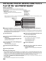
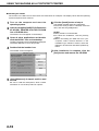
Execute installation from the CD-ROM using the following procedure.
1 Start Windows.
If you click the icon next to a check box and click
the [display README] button, the information of
the specified software will be displayed. When
installing the Printer Administration Utility and the
Printer Status Monitor, read the README text and
check to see if the computer system requirements
are satisfied.
the supplied CD-ROM into a CD2 Insert
ROM drive of your computer.
If your computer is configured for auto start on the
CD-ROM, the language select or user select screen
described in step 5 will appear. (Steps 3 and 4 are
not needed.)
NOTE
The Printer Administration Utility and the Printer
Status Monitor can be used only if this product is
used as a network printer.
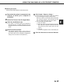
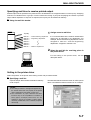
3 On the [Start] menu, click “Run.”
the CD-ROM drive and setup
4 Enter
command. Then click the [OK] button.
Example: If the CD-ROM drive is designated as drive
R, enter “R:\SETUP.EXE”.
8
Click the [Start] button.
the text of Readme First and then click
5 Read
the [Next] button.
The installation screen of the file selected with a
check box will appear. Follow the instructions on
your screen to install the selected printer drivers
and utilities.
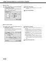
the tools to be installed and click
6 Select
the [Next] button.
When installation is complete, the message
9 “Setup
has finished installing your selected
●
If you select general user tools, you can install
the following software.
PCL5e printer driver, PCL6 printer driver, PCL
display font, Printer Status Monitor
● If you select administrator tools, you can install
the following software.
Printer Administrator Utility
printer drivers and printer utilities that
7 The
can be installed from the CD-ROM will be
package(s).” will appear. Click the [Close]
button.
NOTE
Restart of your computer may be needed
depending on the system. Click [Yes] to restart
the computer.
listed. Select the check boxes of the desired
drivers and utilities and click the [Next]
button.
UNINSTALLING PRINTER DRIVERS
AND PRINTER UTILITIES
When uninstalling a printer driver that has been installed from the Add Printer wizard, right-click the printer to be deleted
from “Printers” of “Control Panel” and select [Delete]. When uninstalling a printer driver that has been installed using the
installer, the Printer Administration Utility or the Printer Status Monitor, use “Add/Remove Programs” of “Control Panel”.
Use the Windows standard operation for each case.
2-3
2
INSTALLING PRINTER DRIVERS USING PLUG &
PLAY OR THE “ADD PRINTER WIZARD”
Before installation
Before installing the printer drivers, check the following items.
● Ensure that your computer system meets the following requirements.
Computer type:
Operating system:
IBM PC/AT or compatible computer
Windows 95
Hardware requirements of the operating system must
Windows 98
be satisfied.
Windows 2000
Windows NT 4.0
Windows Me
When using Plug and Play or using the “Add Printer Wizard” to install printer drivers, enter the directory name
indicated below as a source directory.
Path for using PCL5e driver under Windows 2000
R:\Option\English\2k_pcl5e
Path for using PCL6 driver under Windows 2000
R:\Option\English\2k_pcl6
Path for using PCL5e driver under Windows 95/98/Me
R:\Option\English\9x_pcl5e
Path for using PCL6 driver under Windows 95/98/Me
R:\Option\English\9x_pcl6
Path for using PCL5e driver under Windows NT
R:\Option\English\Nt_pcl5e
Path for using PCL6 driver under Windows NT
R:\Option\English\Nt_pcl6
■ Example of installation of a printer driver using the “Add Printer Wizard” under Windows 98
The installation method of a printer driver under Windows 98 is shown below.
The installation example is described assuming that the printer is connected as a local printer (see “Using this
machine as a local printer” on page 2-2) and that the CD-ROM drive is designated as drive R. The procedure may
differ depending on the system environment.
1 Start Windows 98.
the [Local Printer] radio button and
6 Check
then click the [Next] button.
the supplied CD-ROM into the CD2 Insert
ROM drive.
7 Click the [Have Disk] button.
If your computer is configured for auto start on the
CD-ROM, Readme First screen will appear. Click
[Cancel] to close the screen.
the [Start] menu, select [Settings] and
3 On
then [Printers].
The Printer window will appear.
4 Double-click the [Add Printer] icon.
5 Click the [Next] button.
The “Install From Disk” dialog box will appear.
Enter the file path as follows:
R:\Option\English\9x_pcl5e or
R:\Option\English\9x_pcl6
8 Click the [OK] button.
the printer model to be used and
9 Select
click the [Next] button.
Follow the instructions displayed by the “Add Printer
Wizard.”
■ Installing PCL display fonts
The PCL display fonts are the fonts displayed on your computer screen. The CD-ROM supplied with this product
contains the PCL display fonts that correspond to the resident fonts of this product. These display fonts can be
installed to your computer (Windows 95/98/Me/NT/2000) from the installer. Installation of the PCL display fonts can
be specified in step 6 of “INSTALLING PRINTER DRIVERS AND PRINTER UTILITIES” on page 2-3.
To install the PCL display fonts by Windows basic operation without using the installer(Start Settings Control
Panel Fonts Install New Font), specify the following path.
R:\Option\PCLFont
The CD-ROM drive is designated as drive R as an example.
2-4
SETTING THE PRINTER DRIVER
This section describes the method of changing the printer driver settings from your computer.
If no printer driver has been installed, use the supplied CD-ROM to install it referring to “INSTALLING PRINTER
DRIVERS AND PRINTER UTILITIES” on page 2-3.
Printer driver settings under Windows (selecting and setting print conditions)
Change the settings using the printer properties.
■ Windows NT 4.0 / 2000
■ Windows 95 / 98 / Me
Screens for Windows 98 are used in the description
below.
Screens for Windows NT 4.0 are used in the
description below.
the [Start] menu, select [Settings] and
1 On
then [Printers].
the [Start] menu, select [Settings] and
1 On
then [Printers].
The Printer window will appear.
The Printer window will appear.
the installed printer driver and
2 Right-click
select [Properties].
the installed printer driver and
2 Right-click
select [Document Defaults].
This example is the screen displayed by selecting
AR-P350PCL5e.
This example is the screen displayed by selecting
AR-P350PCL5e.
3
3 Set each item.
Set each item.
For setting items, see
the printer driver help.
4 Click the [OK] button.
For setting items, see
the printer driver help.
4 Click the [OK] button.
NOTE
For the setting concerning optional peripheral devices such as the duplex module, finisher, and stand/3 x 500 sheet
paper drawer, right-click the installed printer, select [Properties], and then open the [Configuration] tab. If you use
this product as a network printer and you have installed the Printer Status Monitor, the configuration of peripheral
devices will be automatically set by clicking “Auto Configuration”. If you click the [Update Tray Status] button in the
[Tray Status] dialog box of the [Paper] tab, the current tray information (paper size, paper type, and quantity of
paper remaining) will be displayed.
2-5
2
PRINTER CONFIGURATION
THROUGH THE NETWORK
If you access the Web pages of this product from your computer using a Web browser such as Netscape Navigator and
Internet Explorer, various settings can be adjusted through the network.
Environment required for accessing Web pages
The following products and computer system requirements are needed for accessing the Web pages of this product.
● Optional print server card (network interface card)
● Recommended Web browser
Microsoft Internet Explorer 4.0 or later or equivalent
Netscape Navigator 4.0 or later or equivalent
NOTE
The following characters cannot be input in the Web pages when setting the Web pages in the Web server
located in this product. Input characters are case-sensitive.
● Characters that cannot be input:
<> ”
● Examples of improper input:
<abc> <abc “abc” “abc
abc”
Accessing Web pages and displaying help
Use the following procedure to access the Web pages. If the help button under the menu frame is clicked, the help
screen for description of various function settings that can be operated remotely from the Web pages for this product
through the network will appear. For the setting of each function, see the detailed description.
1 Open the Web browser on your computer.
the [Help] button under the menu
3 Click
frame.
the IP Address previously specified
2 Input
for this product to the ADDRESS field of
For details of each
function setting, see the
help under the menu
frame. The configuration
settings are described in
detail.
the browser.
Input the IP address
previously specified in
this product. (See page
6-13.)
4 Close the help.
When the connection is
completed, the Web page
information of this product
will be displayed.
2-6
Click the
button. The
display will return to the
Web page information of
this product.
PRINTER CONFIGURATION THROUGH THE NETWORK
Items and outline of menu frame of Web pages
Destination Management
The basic screen on which you can add, modify, or delete the destinations for image data scanned by the network
scanner. The recipient information for facsimile and Internet facsimile features (destination address, facsimile number,
etc.) is described below.
● Up to 500 destinations in total can be registered. In addition, up to 100 destinations can be registered in the file
server and desktop in total.
■ Setting E-mail Destinations
Sets the destination information for E-mail delivery from the network scanner.
Destination E-mail addresses and file types as well as information for destination control (destination name, index,
name for front panel display, etc.) are configured by this control.
■ Setting FTP Destinations
Sets the storage location information for file server storage scan of network scan data. File server information (such
as host name) and file types as well as information for destination control (destination name, user index, name for
front panel display, etc.) are configured by this control.
■ Setting Desktop Destinations
Sets the destination information for desktop delivery of network scan data. Destination computer information (such
as host name) in which the network scanner tool/Sharpdesk has been installed and file types as well as the
information for destination control (destination name, user index, name for front panel display, etc.).
■ Setting Fax Destinations
Sets the fax destination. Fax numbers of recipients and communication mode as well as information for destination
control (destination name, index, name for front panel display, etc.).
■ Setting i-Fax Destinations
Sets the Internet fax destination information. E-mail addresses of destination and file types as well as information
for destination control (destination name, index, name for front panel display, etc.).
■ Setting Group Destinations
Sets destination groups for transmitting data at a time by collecting destinations that have been set as E-mail
destination, fax destination and i-fax destination.
■ Delete Destination
Screen for checking to see if deletion may be executed after selecting a destination to be deleted from the destination
list on the destination management screen and clicking the Delete button. The destination data will be deleted when
the Yes button is clicked.
Fax Memory Box Management
Basic screen for setting the memory area (memory box) for fax images. The memory box has the following three
functions. Up to 100 items in total can be registered for these functions.
● Polled memory box control
● Relay broadcasting
● Confidential reception
■ Polled Memory Box Control
Original data that has been stored in this machine can be transmitted to another facsimile machine when the remote
facsimile machine requests transmission.
■ Confidential reception
Data to be printed is sent to this machine and held until released for printing from the operation panel of this
machine.
■ Relay broadcasting
Memory box information for transmitting received data can be configured by this control.
2-7
2
PRINTER CONFIGURATION THROUGH THE NETWORK
Access setup
The restriction on access to the Web pages and basic settings for using the network scanner and the status/alert Email function are described below.
■ Network Card Setup
A link to the network card Web page for configuring the print server card (network interface card) is provided.
The Admin password is the same as the Web Page password of the network card.
■ Password Setup
Password access to the Web pages can be set. Two types of passwords (user and administrator) are configurable.
The Admin password is the same as the Web Page password of the network card.
■ Network Scanning Setup
Basic setting screen for the network scanner. E-mail subject for scanner delivery, file name, etc. are set. To use the
network scanner, you must set up E-mail & DNS Setup. This screen displays the E-mail & DNS Settings and
provides a link to E-mail & DNS Setup.
■ Status & Alert E-mail Setup
Basic setting screen for the status & alert E-mail system. Machine name, machine code, and machine installation
location are set. To use the status & alert E-mail function, you must set up E-mail & DNS Setup. This screen
displays the settings of E-mail & DNS Settings and provides a link to E-mail & DNS Setup.
■ E-mail & DNS Setup
Basic setting screen for transmitting E-mail. E-mail server, system administrator address, DNS server, etc. are set.
■ Sender E-mail Setup
The sender of E-mail transmissions from the network scanner is configured. The sender will be set as the “From”
item of the E-mail header. Up to 20 senders can be registered and a sender can be selected among them from the
operation panel.
■ Custom Directory Setup
User index names in the display list on the operation panel are set.
■ Status Message Parameters Setup
The parameters used when the current counter information of this machine such as print count, copy count, and
total output is delivered in accordance with the specified schedule by an E-mail status message.
■ Alerts Message Parameters Setup
The parameters for the alert message address information are registered by alert message setup. The alert message
is transmitted when a problem such as a supplies requirement (toner or paper) or errors(device failure or paper
misfeed) occur.
■ SNMP Trap Setup
IP addresses, trap community, and authentic community are set.
2-8
JOB CONTROL
This section describes the operation procedure required for “JOB CONTROL”. To use job control in your print job, select
“Properties” on the printer driver screen, open the “Main” tab, and click “Job control.” The job hold function can be used
only if your printer is equipped with the hard disk drive option.
“JOB CONTROL” operation
1 Normal print
4
Proof print
(For “Normal print”, no input from the operation panel
of the printer is needed.)
The print setting in this mode is the basic print
operation. If no problem such as a paper misfeed
and empty toner occurs in the printer, the print start
operation is completed on the computer and printing
will be executed on the printer.
2
Hold after print
2
This mode can prevent a high-volume misprint when
a lot of sets must be printed. If printing is executed
in this mode, only one set will be printed and the
remaining sets will be held as a hold job.
After checking the finished printout including print
position on paper and stapling position, you can
start printing of the remaining sets from the
operation panel of the printer. Also you can delete
the data without executing printing. (See step 7 on
page 2-10 and step 5 on page 2-11.)
5 Password (5 digits)
Password
In this mode, print data will be held in the hold job
list even after printing is complete. Printing can be
executed again from the operation panel of the
printer if needed. Also the data can be deleted from
the operation panel if it is not necessary.
3
Hold before print
This print mode can reduce the possibility of
missing printout. If printing is made in this mode
from the computer, print data will not be output
immediately and will be stored in the printer as a
hold job until released from the operation panel.
Print start operation can be made on the operation
panel of the printer as needed. Also you can delete
the data without executing printing. (See step 7 on
page 2-10 or step 5 on page 2-11.)
Password
If a password is set in the printer driver setting, a
password entry is needed to start printing of a
password protect job. This mode can increase the
security of hold jobs.
● Hold After Print mode with password:
Password entry on the operation panel of the
printer is needed for additional printing the hold
job.
● Hold Before Print mode with password:
Password entry on the operation panel of the
printer is needed to start printing.
● Proof Print mode with password:
Password entry on the operation panel of the
printer is needed for printing remaining sets after
printing one set. The first set is printed without
password entry.
2-9
JOB CONTROL
Hold job list
If “Print after hold”, “Print before hold” or “Proof print” operation is performed on the computer, print data will be held as
a hold job. (Up to 100 jobs can be held. If the main switch is turned off, the stored data of all jobs in hold will be
cleared.)
If the number of jobs exceeds 100, the job is processed as follows.
● If Hold After Print is executed:
Printing will be executed but the job will not be held. (A notice page will be printed. See page 7-5.)
● If Hold Before Print is executed:
Printing will not be executed and the job will not be held. (A notice page will be printed. See page 7-5.)
● If Proof Print is executed:
Printing of one set will be executed but the job will not be held. (A notice page will be printed. See page 7-5.)
When the machine is being operated from the operation panel on the main unit:
●
For operation from the operation panel with touch panel, see the next page.
1 Press the [MENU] key.
“PRINTJOBS ON HOLD”
will appear in the message display.
2 Press the [OK] key.
ARAI
WORD-1
When the [OK] key is
pressed, a user name
and a file name of the
print data stored as a hold
job will appear.
the first digit of the password and
5 Enter
press the [OK] key.
(needed only if a password has been set)
Be sure to enter the same number that has been
entered on the computer. If no password has been
set, operation of steps 5 and 6 is not needed.
(Proceed to step 7.)
When you press the [OK]
PIN
----- key to register the first
digit after entering it using
or
key on the
the
NOTE:
operation
panel,
“ ” will
The password is entered
appear
and
“-”
at the
one digit at a time starting
second
digit
will
blink.
If
with the first digit. The
you
press
the
[BACK/C]
inactive digits are shown as
key, you can correct the
“-”.
entered number.
Use the same procedure as step 5 to enter
6 the
password from the second digit to the
fifth digit and then press the [OK] key.
PIN
----
3
Select the desired data.
Press the or key on
the operation panel
repeatedly until the
desired print job is
displayed.
4 Press the [OK] key.
execution of printing, cancellation
7 ofSelect
printing or data retention after printing,
and then press the [OK] key.
Deletion or retention of data after printing can be
selected. Alternatively deletion of data without
printing can be selected. Press the or key until
the desired choice appears
PRINT AND DELETE THE
DATA-OK?
PRINT AND SAVE THE
DATA-OK?
DELETE THE DATA-OK?
2-10
●
Data will be deleted
after printing.
●
Data will be held after
printing.
●
Data will be deleted
without printing.
If this item is selected,
the operation will be
complete. Steps 8 and
9 are not needed.
JOB CONTROL
that the desired number of copies is
8 Verify
set.
COPIES
10SET
The number of copies can
be changed by using the
or
key on the
operation panel.
9 Press the [OK] key.
● Printing will start. If printing of another job is being
executed, however, your job will be registered as
a print job. Printing of the job will start after
preceding jobs are completed.
2
10 Operation is now complete.
To continue operation, repeat steps 1 to 9.
When the machine is being operated from the touch panel on a scanner module:
the [PRINT] key to display the printer
1 Press
basic screen.
that the desired number of prints
4 Ensure
is set.
NUMBER OF PRINTS
1
(1 999)
The number of prints can
be changed by using the
PRIN
or key.
PR
2 Select the desired data.
5 Execute printing.
To switch the screen,
touch the or key.
PRINT HOLD JOB LIST
SHARP001
SHARP002
CANCEL
PRINT AND DELETE THE DATA
SHARP003
PRINT AND SAVE THE DATA
SHARP004
the [Numeric] keys to enter the 5-digit
3 Use
password.
(needed only if a password has been set)
ENTER PIN VIA THE 10-KEY.
CANCEL
Be sure to enter the
password that has been
entered on the computer.
If no password has been
set, operation of this step
is not needed.
NOTE:
Each time a number is entered, “–” will change to “ ”.
DELETE
To delete the print data
after completing the print
job, touch the [PRINT
AND DELETE THE DATA]
key. To keep the print data
after printing, touch the
[PRINT AND SAVE THE
DATA] key. To cancel
printing and clear the print
data, touch the [DELETE]
key.
● If you select execution of
the print job, printing will
start. If printing of
another job is being
executed, your job will
be registered as a print
job. Printing of the job
will start after preceding
jobs are completed.
6 Operation is now complete.
2-11
JOB CONTROL
Printer account control
If the key operator program “Auditing mode” is set, the number of printed pages can be accumulated for each account.
The accounts for auditing are the accounts that have been set for counting the number of pages for the printer with a
key operator program. For registration of account numbers, see the key operator programs (page 6-7).
When executing print operation from the computer, you must enter an account number on the setting screen of the
printer driver. The account number entry screen will be displayed by clicking “Job control” in the “Main” tab of the printer
driver.
When an invalid account number is entered or no account number is entered, if key operator program “Cancel jobs of
invalid accounts” has been set, printing will not be performed. To perform printing in any case, disable program “Cancel
jobs of invalid accounts”. In this case, the number of printed pages will be accumulated to “OTHERS”.
The job control screen will always appear when print operation is executed from the printer driver if the “Auto Job
Control review” check box in the “Main” tab of the printer driver is set.
2-12
USING THE MACHINE AS A POSTSCRIPT PRINTER
If an optional PS3 expansion kit (AR-PK1) is installed, this machine can be used as a PostScript compatible printer.
The machine can be used in the Macintosh environment as well as in the Windows environment when used as a
PostScript printer. In the Macintosh environment, however, the printer can be connected only through a network.
Using the printer in the Windows environment
To use this machine as a PostScript printer, the PostScript printer driver or the PPD files (PostScript Printer Description
files) must be installed to your computer. For installation of the printer driver, use the PRINTER UTILITIES CD-ROM
supplied with an optional PS3 expansion kit AR-PK1).
■ Installing the PostScript printer driver
the PRINTER UTILITIES CD-ROM of
1 Insert
the PS3 expansion kit to a CD-ROM drive
of your computer.
2 On the [Start] menu, click “RUN”.
the CD-ROM drive and setup
3 Enter
command. Then click the [OK] button.
Example: If the CD-ROM drive is designated as
drive R, enter “R:\SETUP.EXE”.
the instructions on the screen to install
4 Follow
the desired software.
To install the PostScript printer driver using the “Add Printer” wizard in place of using the installer, enter the directory
name of the file as follows. The directory names for PPD files are also shown in the illustration.
Directory information of the PS3 expansion kit PRINTER UTILITIES CD-ROM
(The CD-ROM drive is assumed to be drive R.)
<Windows 2000>
Path for using PostScript driver
R:\Option\English\2k_PS
Path for using PPD files
R:\Option\English\2k_PSPPD
<Windows 95/98/Me>
Path for using PostScript driver
R:\Option\English\9x_PS
Path for using PPD files
R:\Option\English\9x_PSPPD
<Windows NT>
Path for using PostScript driver
R:\Option\English\NT_PS
Path for using PPD files
R:\Option\English\NT_PSPPD
■ Installing the PPD files (PostScript printer description files)
Insert the PRINTER UTILITIES CD-ROM of the PS3 expansion kit to a CD-ROM drive of your computer. The installation
procedure is basically the same as the procedure described on page 2-4 that is performed by using the “Add Printer”
wizard for installing a printer driver. The following items, however, are different.
● The PRINTER UTILITIES CD-ROM of a PS3 expansion kit is used.
● The path of the PPD files must be entered in step 7 on page 2-4. The path for each Windows version is shown below.
(The CD-ROM drive is assumed to be drive R.)
● Windows 2000
R:\Option\English\2k_PSPPD
● Windows 95/98/Me
R:\Option\English\9x_PSPPD
Windows NT
R:\Option\English\NT_PSPPD
● When selecting the printer model in step 9 on page 2-4, select the PPD file name with your printer model.
2-13
2
USING THE MACHINE AS A POSTSCRIPT PRINTER
■ PS display font
The PRINTER UTILITIES CD-ROM of a PS3 expansion kit contains PS display fonts. Install the PS display fonts
as needed when the PostScript printer driver is installed. To install the PS display fonts, select it when installing the
PostScript printer driver using the installer.
■ Installing the resident font information for PPD (Windows 95/98/Me)
After installing the PPD files, follow the procedure below to install the resident font information.
NOTES
● Before installing the resident font information, be sure to install the PPD files.
● When installing the resident font information, be sure to close all other open applications.
● When the printer is used as a network printer, if you have changed the port for the printer from Properties of
the printer driver, reinstall the resident font information.
The screens in the Windows 98 environment are used below as examples.
1 Start Windows.
the PRINTER UTILITIES CD-ROM of
2 Insert
a PS3 expansion kit into a CD-ROM drive.
5 Click the [OK] button.
The following window will appear.
If your computer is configured for auto start on the
CD-ROM, the package selection screen will appear.
Click the [Cancel] button.
3 On the [START] menu, click “RUN”.
the
CD-ROM
drive
and
4 Enter
“Option\English\9x_psppd\Pfmsetup.exe”,
and click the [OK] button.
If the CD-ROM drive is designated as drive R, type
“R:\Option\English\9x_psppd\Pfmsetup.exe”
and click the [OK] button.
The following window will appear.
If the PPD files have not been installed, a message
indicating it will appear and the resident font
information cannot be installed.
6 Click the [OK] button.
installing the resident font, restart
7 After
Windows.
Installation of the resident font is complete.
2-14
USING THE MACHINE AS A POSTSCRIPT PRINTER
Using the printer in the Macintosh environment
To use the printer in the Macintosh environment, the PPD files (PostScript printer description files) for Macintosh
contained in the PRINTER UTILITIES CD-ROM of an optional PS3 expansion kit must be installed. The printer can be
used as a PostScript compatible printer. The printer, however, must be connected to the computer through a network.
An optional Print Server Card (AR-NC5J) is needed for network connection. Also the Macintosh computer must be
equipped with an Ethernet port. If your computer is not equipped with an Ethernet port, install an Ethernet interface.
NOTE
If this printer is connected to the computer via a cross cable, be sure to turn on the Macintosh computer before
turning on this printer. If not, the printer cannot be recognized as a network printer.
■ PPD files
The PPD files for Macintosh are the files which a Macintosh computer refers to when using its LaserWriter printer
driver for printing.
■ SHARP PPD Utility
The SHARP PPD Utility is used to register account numbers and passwords when the auditing mode (page 6-7) or
the job retention function with password (page 2-9) is used. This utility is also used to change the registered account
numbers and passwords.
■ Display fonts
The PRINTER UTILITIES CD-ROM contains the display fonts for Macintosh. If you use the PPD files, install the
display fonts as needed.
■ Before installing the PPD files and the PPD Utility
Before installing the software above, check the hardware and software requirements.
Computer:
Operating system:
Printer driver:
Apple Macintosh series
Apple Power Macintosh series
Mac OS 8.51 to 9.x
LaserWriter 8 version 8.4.1 or later
For other conditions such as CPU and RAM capacity, requirements of the operating system must be satisfied.
Ensure that LaserWriter 8 has been installed in the Macintosh system. If not, install it from the system CD-ROM
supplied with your Macintosh computer.
2-15
2
USING THE MACHINE AS A POSTSCRIPT PRINTER
■ Installing the utilities
The screens in the Mac OS 9.0 environment are used below as examples. The display varies with the operating
system and printer driver versions.
on the computer
1 Turn
operating system.
and start the
the supplied SHARP PS3 Expansion
2 Insert
Kit AR-PK1 PRINTER UTILITIES CD-ROM
into a CD-ROM drive.
The AR-PK1 icon will appear on the desktop.
all other applications and double3 Close
click the AR-PK1 icon on the desktop.
The files contained in the CD-ROM will be displayed.
The Printer Manual is not for this product.
4 Double-click the Installer icon.
The installer screen will appear.
Click [Reference] of steps 2 and 3 to read
5 the
text.
Be sure to read the descriptions, which contain
information on use of this product as a printer.
2-16
Click the [Install] button of step 4.
6 The
SHARP Installer dialog box will appear.
Ensure that “Easy Install” is selected, select the
drive, and click the [Install] button.
NOTES
● “Easy Install” is recommended.
● To cancel the installation, click the [Cancel]
button.
● When uninstalling the PPD files from your
computer, select “Custom Remove” on the
installation type selection window, select the
features to be removed, and click the [Remove]
button.
installation is complete, click the
7 After
[Quit] button and remove the CD-ROM.
USING THE MACHINE AS A POSTSCRIPT PRINTER
■ Selecting the printer
Follow the procedure below to select the printer.
that the printer is connected to the
1 Ensure
network to which your computer is
connected.
2 Select the Chooser from the Apple Menu.
the LaserWriter 8 icon.
3 Click
The names of connected printers are displayed in
●
the right hand box. If multiple AppleTalk zones are
displayed, select the zone which includes the desired
printer.
the desired printer.
4 Select
The default printer name of this product is
●
“SCXXXXXX” (XXXXXX: 6 alphanumeric characters).
The printer name can be changed by adjusting the
setting for the Print Server Card (AR-NC5J).
‘Create’, ‘Setup’ or ‘Setup...’.
5 Click
(Phrase depends on the version of MAC OS installed)
●
●
If you are setting this printer for the first time:
When the “Select a PostScript Printer Description
File:” dialog box appears, select the PPD file name
with your printer model name and click ‘Select’.
If you are setting this printer again:
1) Click ‘Auto Setup’.
2) When the “Select a PostScript Printer Description
File:” dialog box appears, select the PPD file
name with your printer model name and click
‘Select’.
3) Click ‘OK’.
● Printer configuration will be automatically set.
6 Click the Close box to close the Chooser.
2-17
2
USING THE MACHINE AS A POSTSCRIPT PRINTER
■ Paper setting
“Page Setup” from the [File] menu
1 Select
of application software.
The following display will appear. (The display varies
with the operating system versions, printer driver
versions, and application software.)
2
Adjust each setting.
●
Paper size, reduction/enlargement, and orientation
can be set.
3 Click the [OK] button.
■ Print condition setting
“Print” from the [File] menu of
1 Select
application software.
Adjust each setting.
2 Number
of copies, page range, and other settings can
The following display will appear. (The display varies
with the operating system versions, printer driver
versions, and application software.)
be made.
If the printer has been configured for the auditing mode,
an assigned 5-digit account number must be specified.
To use the job retention with password, specify a fivedigit password.
To specify an account number or a password for the job
retention function, click “ ” to the right of ‘General’ and
select ‘Job Control’.
● The account numbers used for printing are common
to those for copying. The account numbers for printing
must be registered to the computer using the PPD
utility.
3
2-18
Click the [Print] button.
USING THE MACHINE AS A POSTSCRIPT PRINTER
■ Installing the display fonts
The display fonts for Macintosh are contained in the Font folder of the AR-PK1 PRINTER UTILITIES CD-ROM.
Install the display fonts as needed.
Copy the required display font files to the Fonts folder under the System folder of your computer.
NOTE
If any malfunction occurs due to the installation of display fonts, delete the fonts from the system.
■ Using the SHARP PPD Utility
Before using the printer auditing mode or the job retention function with password from a Macintosh computer, you
must use the PPD Utility to register account numbers and passwords. The PPD Utility is installed together with the
PPD files using the installer for Macintosh contained in the SHARP PS3 Expansion Kit AR-PK1 PRINTER UTILITIES
CD-ROM.
This utility allows up to 20 account numbers to be registered for the computer. The account numbers are the same
as those for the copier auditing mode and must be registered using one of the key operator programs for the copier
feature. When printing in the auditing mode, one of the registered account numbers must be specified on the screen
used for setting print conditions. Also use this utility to change the registered account numbers.
When using the job retention function with password, a password must be specify when printing. This utility allows up
to 20 passwords to be registered. One of the passwords must be specified when you set the print conditions.
To start this utility, select SHARP AR-PK1 Extras folder and then double click the PPD Utility icon.
NOTE
Do not use the AR230_270 PPD Utility. This utility is not for this model.
register a security password for the job
3 To
retention function, click the [Add] button
for Confidential Print Password. The
Confidential Print Password screen will
appear. Enter a 5-digit number in the box
and click the [OK] button.
To delete a registered security password, select the
password in the box and click the [Delete] button.
save the registered account numbers
4 To
and passwords and to exit the utility, click
the [Save & Quit] button.
the [Select] button and select the PPD
1 Click
files for your printer.
If the PPD file is changed using this utility,
5 be
sure to select the printer again through
the Chooser. Use the procedure described
in “Selecting the Printer” on page 2-17.
register an account number for the
2 To
computer, click the [Add] button for
Account Number. The Account Number
screen will appear. Enter a 5-digit account
number and click the [OK] button.
To delete a registered account number, select the
account number in the box and click the [Delete] button.
2-19
2
CHAPTER 3
PRINTER BASIC SETTINGS
This chapter describes the following items.
1. Printer configuration settings
2. Custom settings based on the customer’s operating conditions.
Page
MAKING CONFIGURATION SETTING ...................................................
● Operation procedure common to all printer configuration settings
(items that can be set from the operation panel) ..............................
● Default settings ..................................................................................
● PCL settings .......................................................................................
● PostScript settings .............................................................................
CUSTOM SETTINGS ...............................................................................
● Operation procedure common to all custom settings
(items that can be set from the operation panel) ..............................
● Setting items ......................................................................................
3-2
3-2
3-4
3-5
3-5
3-6
3-6
3-8
3-1
MAKING CONFIGURATION SETTING
The printer configuration setting allows basic printer settings to be made. The items set with the printer configuration
settings are shown below.
● Default settings ................................ Basic settings used in printing (See page 3-4.)
● PCL settings .................................... Sets a PCL symbol set. (See page 3-5.)
● PostScript settings* ......................... Sets whether a PostScript error page is printed or not when a PostScript error
has occurred. (See page 3-5.)
* An optional PS3 expansion kit is needed.
Operation procedure common to all printer configuration settings
(items that can be set from the operation panel)
When the machine is being operated from the operation panel on the main unit:
the [MENU] key to display the
1 Press
configuration setting menu screen.
Press the [MENU] key
repeatedly until “SET
OPERATIONS CONDITIONS ” appears.
Any print jobs held in the
printer and any job
currently transmitted to
the printer will be printed
in the former print
conditions.
2 Press the [OK] key.
the
5 Press
setting.
or
key to display the desired
For the details of each setting item, see the
description on and after page 3-4.
6 Press the [OK] key.
“ ” will be displayed to
the right of the selected
item and setting will be
registered. To set another
item, press the [BACK/C]
key to return to step 3 and
repeat the procedure to
step 6.
setting is complete, press the
7 When
[MENU] key to return to the basic screen.
the or
3 Press
setting item.
key to display the desired
NOTE
If the [BACK/C] key is pressed after each setting is
complete, the display that has called the setting will
appear again. If selection of a number is mistaken
during setting operation, press the [BACK/C] key
to correct the selected number.
4 Press the [OK] key.
3-2
MAKING CONFIGURATION SETTING
When the machine is being operated from the touch panel on a scanner module:
the [CONDITION SETTINGS] key on
1 Touch
the printer screen to display the
configuration setting menu screen.
Any print jobs held in the
printer and any job
currently transmitted to
the printer will be printed
in the former print
conditions.
CONDITION
SETTINGS
the desired setting on the setting
3 Touch
screen of the desired item and touch the
[OK] key.
To set another item, repeat steps 2 and 3.
finish the setting operation, touch the
4 To
[EXIT] key.
CONDITION SETTINGS
DEFAULT SETTINGS
the key of the desired item to display
2 Touch
its setting screen.
DEFAULT SETTINGSPCL SETTINGS PCL SETTINGS
3
PostScript SETTINGS
PostScript SETTINGS
CONDITION SETTINGS
DEFAULT SETTINGS
DEFAULT SETTINGSPCL SETTINGS PCL SETTINGS
PostScript SETTINGS
PostScript SETTINGS
Detailed descriptions for configuration setting start
on the next page.
Supplementary explanation of key operation
for configuration setting
(when using the touch panel)
These keys and indicator are available on setting
screens that require the entry of numerical values.
20
OK
DEFAULT SETTINGS
SMOOTHING
ORIENTATION
DEFAULT OUTPUT TRAY
(1-999)
P
COPIES
1
DEFAULT PAPER SIZE
A4
1/2
DEFAULT PAPER TYPE
The name of the configuration category or particular item to be set will appear on the touch key. A touch of the
key will select the item displayed.
Check mark boxes are touch keys that show the status of selections. A box with a check mark means the
function is “on” (enabled) and an unchecked box means the function is “off” (disabled). Alternate touches of a
box will change the on/off status.
If a configuration step requires more than one screen to display all available settings for a configuration step,
[ ] and [ ] arrow touch keys on the setting screens allow access to the available selections on all screens. If
a selection is accepted on one of the screens by a press of the [OK] key, the display will return through the
previous selection screens within the same setting step to confirm the settings. After all settings are confirmed,
the [OK] key must be pushed again to advance to the next step.
The currently set numerical value is displayed.
Numerical values can be set by touching the [ ] and [ ] keys.
3-3
MAKING CONFIGURATION SETTING
Default settings
The default settings allow detailed print conditions to be set for printing without any printer driver (for example, printing
from MS-DOS and printing from a computer without any printer driver installed). The setting items are shown below.
NOTE
When some items can be set both in the printer driver and on the operation panel, the values set in the printer
driver override those set on the operation panel. For items that can be set in the printer driver, perform setting
in the printer driver.
■ Smoothing
SMOOTHING reduces jaggies seen at roundish
curved portions of characters and images to be
printed and improves pseudo resolution.
Default setting: On
Smoothing on or off can be selected.
■ Copies
COPIES is set when the number of copies to be
printed is set.
Default setting: 1
The number of copies can be set from 1 to 999.
■ Orientation
ORIENTATION allows portrait orientation or
landscape orientation to be selected for printing.
Default setting: PORTRAIT
PORTRAIT or LANDSCAPE can be set.
■ Default paper size
The paper size to be used for printing in the normal
conditions is set.
Printing will be performed onto the specified size
paper unless otherwise specified.
Default setting: 8-1/2 x 11 or A4
11 x 17, 8-1/2 x 14, 8-1/2 x 13, 8-1/2 x 11, 7-1/4 x 101/2, 5-1/2 x 8-1/2, A3, B4, A4, B5 or A5 can be set.
(If the operation panel on the main unit is used, the
sizes are displayed as follows in the display:
LEDGER, LEGAL, FOOLSCAP, LETTER,
EXECUTIVE, INVOICE, A3, B4, A4, B5, and A5.)
3-4
■ Default paper type
The paper type to be used for printing in the normal
conditions is set.
Printing will be performed onto the specified type
paper unless otherwise specified.
Default setting: PLAIN
Plain paper, pre-printed paper, recycled paper,
transparency film letter head paper, pre-punched
paper or color paper can be set.
■ Default output tray
The output tray to be used for printing in the normal
conditions is set. Printed sheets will be output to the
specified tray unless otherwise specified by
application software.
Default setting: Depends on installation of peripheral
devices.
The trays that can be selected depend on installation
of peripheral devices. This item itself may not be
selected.
■ 2-SIDED PRINT
Printing mode, 1-SIDED or 2-SIDED, to be used for
printing in the normal condition is set.
This key can not be selected on the printer without
the duplex module.
Default setting: 1-SIDED
1-SIDED, 2-SIDED (BOOK) or 2-SIDED (TABLET)
can be set.
MAKING CONFIGURATION SETTING
■ Line thickness
This setting is used to adjust the line width of vector graphics. For example, if you desire a finer line, select a value
from 0 to 4. If you desire a thicker line, select a value from 6 to 9. To return to the standard line thickness, select 5.
Use this setting for special applications such as CAD when lines do not appear with sufficient clarity. For regular
applications, there is usually no need to change the setting.
Default setting: 5
The relation between the setting values and the change of line thickness are as follows.
Value
0
1
Thickness change 1 dot *
1
2
3
4
5
6
7
8
9
50%
75%
90%
95%
100%
105%
110%
125%
150%
* All lines are 1-dot lines.
1
■ Extra print mode
When you have a large number of single print jobs, this setting can be used to shorten the waiting time between
print jobs and increase efficiency. Normally there is no need to turn this setting on.
When this setting is turned on, multiple single print jobs are displayed in the Job status screen as one print job.
Note that the "Notify Job End" function does not operate (even if turned on) when Extra print mode is turned on.
When turned on, Extra print mode combines single print jobs into one print job. However, if any of the print jobs are
as described in A or B below, Extra print mode will turn off or stop functioning.
A. One of the following print conditions change between print jobs:
Two-sided printing to one-sided printing / one-sided printing to two-sided printing / binding method of twosided printing / orientation of two-sided printing / paper type / output tray / toner save / smoothing / binding
position / binding width / halftone *1
*1 An optional PS3 expansion kit is needed.
B. One of the following print modes is selected for a print job:
Account control / Two or more copies / Job retention *2 / Saddle stitch / Staple / Punch / Different first page /
Transparency inserts
*2 An optional hard disk drive must be installed.
PCL settings
PCL SETTINGS is used to assign a part of character codes to characters of a country in the PCL symbol set. (Used
when different symbols are used depending on the country.)
Default setting: “1” (Roman-8)
For setting items of the symbol set, see page 7-6.
The list of the numbers to be set and their corresponding symbol sets can be printed using “PCL symbol set list
printing” (see page 3-8).
When using the operation panel on the main unit, select the desired symbol set item and register it. When using the
operation panel with touch panel, select the number that corresponds to the desired symbol set and register it.
PostScript settings
This setting specifies whether an error page describing the cause of an error is printed or not when a PostScript error
has occurred.
Selections are available to choose printing or not printing of error pages.
Default setting: Not print
3-5
3
CUSTOM SETTINGS
Custom settings are used for various settings based on the customer operating conditions. The items that can be set
with the custom settings are shown below.
● Total count ....................................... The number of printed pages and the like are displayed. (See page 3-8.)
● Display contrast*1 ............................ The display contrast of the operation panel is adjusted. (See page 3-8.)
● List print ........................................... Used to print a list of settings that have been made or a font list. (See page
3-8.)
● Clock ............................................... The date and time of the built-in clock of the printer are set.
● Tray settings .................................... The paper type and paper size for each tray are set.
● Auto tray switching .......................... Used to switch automatically the paper tray of the same paper size when
paper runs out in continuous printing.
For the items below, detailed setting procedure is described in the facsimile operation manual.
● Address control*3 ........................ Used to register destination E-mail addresses, fax numbers, and Internet
fax addresses. Also group entry, memory box entry, custom index entry,
and scanner sender entry can be set.
2
● Receive mode* .......................... The fax receive mode (automatic or manual) is set.
● Fax data forward*2 ...................... Received fax data in memory can be forwarded to another destination.
● Key operator programs .................... Setting programs are provided for key operators (administrators of this machine).
If this product is equipped with a scanner module, this key will appear in the
CUSTOM SETTINGS menu screen. For settings, see page 6-1.
*1 Can be set if this product is equipped with a scanner module.
*2 Can be set if this product is equipped with a scanner module and the facsimile feature can be used.
*3 Can be set if this product is equipped with a scanner module and the facsimile feature or the network scanner
feature can be used.
Operation procedure common to all custom settings (items that can be set
from the operation panel)
When the machine is being operated from the operation panel on the main unit:
the [MENU] key to display the custom
1 Press
settings menu screen.
Press the [MENU] key
repeatedly until the
message “CUSTOM
SETTINGS” appears.
Any print jobs held in the
printer and any job
currently transmitted to
the printer will be printed
in the former custom
setting conditions.
2 Press the [OK] key.
the or
3 Press
setting item.
key to select the desired
4 Press the [OK] key.
the
5 Press
setting.
or
key to select the desired
For details of each setting item, see the description
on page 3-8.
3-6
CUSTOM SETTINGS
setting is complete, press the
7 When
[MENU] key to return to the basic screen.
6 Press the [OK] key.
“ ” will be displayed to
the right of selected item,
and the setting will be registered. Depending on the
setting item, additional
item selection and registration operation may be
needed. In this case, use
the
or
key to select
an item and press the
[OK] key to register it. To
set another item, press
the [BACK/C] key and
repeat steps 5 and 6.
NOTE
If the [BACK/C] key is pressed after each setting
is complete, the display that has called the setting
will appear again. If selection of a number is
mistaken during setting operation, press the
[BACK/C] key to correct the selected number.
3
When the machine is being operated from the touch panel on a scanner module:
the [CUSTOM SETTINGS] key when
1 Press
the printer screen is displayed to display
the custom settings menu screen.
Any print jobs held in the
printer and any job
currently transmitted to
the printer will be printed
in the former custom
setting conditions.
the key of the desired item to display
2 Touch
its setting screen.
CUSTOM SETTINGS
the desired setting on the setting
3 Touch
screen of the desired item and touch the
[OK] key.
CUSTOM SETTINGS
TRAY SETTINGS
OK
TYPE / SIZE
PRINT
COPY
FAX
PLAIN / 8 X11
TRAY 2
PLAIN / AUTO-INCH
TRAY 3
RECYCLED / AUTO-INCH
To set another item, repeat steps 2 and 3.
finish the setting operation, touch the
4 To
[EXIT] key.
TOTAL COUNT
DISPLAY
CONTRAST
LIST PRINT
CLOCK
CUSTOM SETTINGS
TRAY SETTINGS
ADDRESS
CONTROL
RECEIVE MODE
FAX DATA
FORWARD
TOTAL COUNT
DISPLAY
CONTRAST
LIST PRINT
CLOCK
TRAY SETTINGS
ADDRESS
CONTROL
RECEIVE MODE
FAX DATA
FORWARD
KEY OPERATOR PROGRAMS
1/2
1/
2
TRAY 1
KEY OPERATOR PROGRAMS
Detailed descriptions for custom settings start on
the next page.
CUSTOM SETTINGS
TRAY SETTINGS
OK
TYPE / SIZE
PRINT
COPY
FAX
1/2
1/
2
TRAY 1
PLAIN / 8 X11
TRAY 2
PLAIN / AUTO-INCH
TRAY 3
RECYCLED / AUTO-INCH
Depending on the setting item, additional item
setting keys may be displayed and page switching
keys may be displayed.
Check mark boxes are touch keys that show the
status of selections. A box with a check mark means
the function is “on” (enabled) and an unchecked box
means the function is “off” (disabled). Alternate
touches of a box will change the on/off status.
3-7
CUSTOM SETTINGS
Setting items
■ Total count
The number of total printed pages in this product
can be displayed and printed.
If the product is equipped with an optional scanner
to include copying and facsimile functions, the
number of copies made and facsimile images sent
can also be displayed or printed.
■ Display contrast
Can be set if this product is equipped with a scanner
module.
This item is used to adjust the contrast of the touch
panel display.
■ List print
Test pages such as a list of setting items configured
in this product and a list of the resident fonts for
checking can be printed.
The types of test pages are shown below.
● All custom setting list
The settings in the printer feature (condition
settings and custom settings) are printed. The
key operator program settings are not printed.
● Printer test page
PCL font list printing: A list of fonts that can be
used with the PCL printer drivers is printed.
PCL symbol set printing: A PCL symbol set list
is printed.
NIC page printing: A list of settings used by the
NIC (Network Interface Card), namely the print
server card, is printed.
PostScript font list printing: A list of fonts that
can be used with the PostScript printer driver is
printed.
Option font list printing: A list of option fonts (ARPF1) is printed.
●
●
●
●
●
NOTE
If test page printing is disabled with key operator
program “DISABLE TEST PAGE PRINTING” (page
6-11), the printer test pages cannot be printed.
■ Clock
The date and time of the built-in clock of this product
are set. These settings will be used for the functions
that require date and time information.
3-8
■ Tray settings
Paper type, paper size, operation mode, and use of
automatic tray switching are set for each tray.
For details on setting the paper type and paper size,
see pages 1-19 and 1-20.
“Operation mode” means copy, print or fax mode.
Use of a paper tray is set for each mode. This setting
is available when the machine is operated from the
touch panel on a scanner module.
When the machine is being operated from the
operation panel on the main unit, use the item “Auto
tray switching” described below for setting the
automatic tray switching function.
■ Auto tray switching
If the auto tray switching function is set and more
than one tray of the same paper size is installed in
this product, printing can be continued by switching
automatically the paper tray when paper of a tray
runs out. This item is used to enable the auto tray
switching function. When the machine is operated
from the touch panel on a scanner module, use the
item “Tray settings” to set this function.
CHAPTER 4
TROUBLESHOOTING
AND MAINTENANCE
This chapter describes misfeed removal, user maintenance, etc.
Page
MISFEED REMOVAL . . . . . . . . . . . . . . . . . . . . . . . . . . . . . . . . . . . . . . . . .
● General misfeed removal procedure . . . . . . . . . . . . . . . . . . . . . . . . . .
● Misfeed removal guidance . . . . . . . . . . . . . . . . . . . . . . . . . . . . . . . . . .
● Misfeed in the paper feed area . . . . . . . . . . . . . . . . . . . . . . . . . . . . . .
● Misfeed in the transport area, fusing area, and exit area . . . . . . . . . .
● Misfeed in the duplex module . . . . . . . . . . . . . . . . . . . . . . . . . . . . . . .
TROUBLESHOOTING . . . . . . . . . . . . . . . . . . . . . . . . . . . . . . . . . . . . . . . .
USER MAINTENANCE . . . . . . . . . . . . . . . . . . . . . . . . . . . . . . . . . . . . . . .
● Cleaning the scanner module . . . . . . . . . . . . . . . . . . . . . . . . . . . . . . .
4-2
4-2
4-3
4-4
4-6
4-7
4-8
4-11
4-11
4-1
MISFEED REMOVAL
When the machine is being operated from the operation panel on the main unit:
●
If the machine is not equipped with a scanner, all messages will appear on the display panel of the main unit. For
machines equipped with a scanner, messages will appear on the touch panel display on the scanner module.
When a misfeed has occurred, printing will stop and the message shown below will appear. Follow the procedure below
to remove misfed paper.
PAPER JAM.
[i]
NOTES
● Do not damage or touch the photoconductive
drum. (See pages 1-5 and 4-6.)
● Be careful not to tear the misfed paper during
removal.
● If paper is accidentally torn during removal, be
sure to remove all pieces.
CAUTION
The fusing unit is hot. Take
care in removing paper.
Fusing unit
General misfeed removal procedure
If the INFORMATION key is pressed when a misfeed has occurred, messages will appear giving guidance for
misfeed removal. The messages will appear in sequence and can be viewed by using the and keys.
1 Press the INFORMATION key.
2 Press the
key.
Use the or keys on
the operation panel to
scroll through the
guidance messages.
The messages in the table below provide guidance for
misfeed removal. For more detailed guidance refer to
the pages indicated in the table.
Message
PULL OUT TRAY * AND CHECK THE PAPER.
OPEN THE LOWER LEFT COVER.
OPEN THE LEFT COVER.
REMOVE PAPER FROM BYPASS TRAY.
OPEN THE DUPLEX COVER.
OPEN THE MAIL-BIN COVER.
OPEN THE CENTER COVER.
OPEN THE FINISHER TOP COVER.
SLIDE THE FINISHER AWAY FROM MACHINE.
OPEN THE FINISHER FRONT COVER.
Page
4-4
4-5
4-6
4-7
4-7
5-8
5-8,5-14
5-14, 5-24
5-24
5-24
the INFORMATION key to close the
3 Press
misfeed removal guidance.
4-2
MISFEED REMOVAL
When the machine is being operated from the touch panel on a scanner module:
When a misfeed has occurred during printing, the message “A MISFEED HAS OCCURRED.” will appear in the
touch panel display of the operation panel and printing including copying and facsimile output will stop. The
approximate misfeed locations are indicated with “ ” shown in the illustration below. The page numbers for detailed
information on misfeed removal are also shown.
Misfeed in the scanner module .
(See the operation manual for copier operation.)
Misfeed in the finisher (page 5-14)
Misfeed in the mail-bin
stacker (page 5-8)
Misfeed in the transport area, fusing
area, and exit area (page 4-6)
Misfeed in the duplex module
(page 4-7)
Misfeed in the bypass tray (page 4-7)
Misfeed in paper tray 1 (page 4-4)
Misfeed in the multi purpose drawer
(page 4-5)
Misfeed in the stand/MPD & 2000
sheet paper drawer (page 4-5)
Misfeed in the saddle
stitch finisher (page
5-24)
Misfeed in the
multi purpose
drawer (page
4-5)
Misfeed in the stand/3 x 500 sheet
paper drawer (page 4-5)
NOTES
● Facsimile reception data is always temporarily stored in memory. After misfed paper is removed, any received
data in memory will be automatically printed.
● If the machine is performing a scanning operation, vibrations resulting from hard operation of machine covers
or trays during misfeed removal will cause uneven scanning. Also if a hard disk drive unit is installed, it may
malfunction due to vibration.
NOTES
● Do not damage or touch the photoconductive drum.
(See pages 1-5 and 4-6.)
● Be careful not to tear the misfed paper during
removal.
● If paper is accidentally torn during removal, be sure
to remove all pieces.
Misfeed removal guidance
CAUTION
The fusing unit is hot. Take
care in removing paper.
Fusing unit
Misfeed removal guidance can be displayed by touching the INFORMATION key on the touch panel after a misfeed
has occurred.
INFORMATION
4-3
4
MISFEED REMOVAL
Misfeed in the paper feed area
NOTE
Be sure to follow the misfeed removal sequence. Do not pull the paper tray out first as paper may be located
between the paper tray and the paper feed section. If the tray is pulled first, the misfed paper may be torn and
difficult to remove. The following procedure shows the removal sequence when the machine is equipped with a
duplex module. If the machine is not equipped with a duplex module or any output device, the procedure is
basically the same. The left side of the machine must be opened and cleared before the paper tray is pulled out.
■ Misfeed in paper tray 1
the duplex module and slide it to
1 Unlatch
the left.
Unlatch the module and
gently move the module
away from the machine.
If the machine is not
equipped with a duplex
module, open the side
cover similarly.
2 Remove the misfed paper.
Be careful not to tear the
misfed paper during
removal.
NOTE
The paper may not be extending out far from inside
the machine but must be removed if it is possible to
grasp it. If it is not possible to grasp it, go to the next
step.
paper is not found in step 2, pull
3 Ifoutmisfed
paper tray 1 and remove the misfed
paper.
Be careful not to tear the
misfed paper during
removal.
4 Gently close the paper tray.
Push the paper tray back
into the machine.
4-4
5 Gently close the duplex module.
If the machine is not
equipped with a duplex
module, close the side
cover.
After closing, confirm that
the misfeed message has
been cleared and the
normal display appears.
NOTE
If paper drops beyond the rear side of the paper tray
that has been pulled out, remove the paper tray and
then remove the paper. (For removal of the paper tray,
see the illustration below.)
After pulling out the
paper tray until it stops,
gently lift and pull the
tray to remove it. To
reinstall the paper tray,
insert it at an angle and
then push it into the
machine.
To remove a paper tray from a stand/paper drawer,
pull the tray out until it stops then rotate it to the left
to disengage it from the stand. When reinstalling it,
place the left rear of the drawer into the slot and rotate
the drawer to the right and into the stand.
Installation of trays in the stand/3x500 sheet
paper drawer
The middle and lower trays cannot be installed in
the upper tray position and the upper tray cannot be
installed to the middle and lower tray positions.
(These cannot be pushed into the machine.)
Take care not to install a tray to an improper position
after removing the tray.
MISFEED REMOVAL
■ Misfeed in the multi purpose drawer
Unlatch the duplex module and slide it to
the left.
1
Unlatch the module and
gently move the module
away from the machine.
If the machine is not
equipped with a duplex
module, open the side
cover similarly.
the left cover of the stand/paper
2 Open
drawer.
Hold the knob and gently
open the cover.
If the machine is not
equipped with a stand/
paper drawer, open the left
cover of the multi purpose
drawer.
3 Remove the misfed paper.
Be careful not to tear the
misfed paper during
removal.
■ Misfeed in the stand/3 x 500 sheet paper
drawer
For misfeed removal in the upper tray, follow the
procedure of “Misfeed in the multi purpose drawer”
shown to the left to remove the misfed paper.
■ Misfeed in the stand/MPD & 2000 sheet paper
drawer
For misfeed removal in the upper tray, follow the
procedure of “Misfeed in the multi purpose drawer”
shown to the left to remove the misfed paper. For
misfeed removal in the lower large capacity tray, follow
the procedure below.
steps 1 to 4 of “Misfeed in the multi
1 Follow
purpose drawer” shown to the left.
paper is not found in step 1, refer
2 Iftomisfed
“Misfeed in paper tray 1” on the previous
page.
paper is not found in steps 1 and
3 If2,misfed
pull out the large capacity tray (lower
tray) and remove the misfed paper as
shown in the illustrations below.
NOTE
The paper may not be extending out far from inside
the machine but must be removed if it is possible to
grasp it. If it is not possible to grasp it, go to the next
step.
the left cover of the stand/paper
4 Close
drawer.
Raise the paper guide and
remove the misfed paper.
After removing the misfed
paper, be sure to return
the paper guide.
5 Gently close the duplex module.
If the machine is not
equipped with a duplex
module, close the side
cover.
After closing, confirm that
the misfeed message
has been cleared and the
normal display appears.
4 Gently close the large capacity tray.
Push the paper tray all the
way into the machine.
paper is not found in step 3, refer
6 Iftomisfed
“Misfeed in paper tray 1” (steps 1 to 5 on
close the duplex module.
5 Gently
If the machine is not equipped with a duplex module,
the previous page) to remove the misfed
paper.
close the side cover.
After closing, confirm that the misfeed message
has been cleared and the normal display appears.
4-5
4
MISFEED REMOVAL
Misfeed in the transport area, fusing area, and exit area
CAUTION
The fusing unit is hot. Take care in removing paper.
(Do not touch the metal parts.)
1
If paper is misfed in the
fusing area, turn roller
rotating knob B in the
direction of the arrow to
remove the misfed paper.
Roller rotating knob B
Unlatch the duplex module and slide it to
the left.
Unlatch the module and
gently move the module
away from the machine.
If the machine is not
equipped with a duplex
module, open the side
cover similarly.
the misfed paper as shown in the
2 Remove
illustrations below.
Roller rotating knob A
If paper is misfed in the
transport area, turn roller
rotating knob A in the
direction of the arrow to
remove the misfed paper.
NOTE
Do not touch or damage
the transfer roller.
CAUTION
The fusing unit is hot. Take care in removing paper.
(Do not touch any metal parts.)
Fusing unit open tab
If the misfed paper is
inside the fusing area,
turn down the fusing unit
open tab to open the
fusing unit and remove
the misfed paper.
If paper is misfed in the
exit area, remove it as
shown while taking care
not to tear the paper.
If the duplex module is
equipped with an exit tray
and paper is misfed in the
exit area, remove the
misfed paper as shown in
the illustration.
Transfer roller
3 Gently close the duplex module.
Do not touch or damage
the photoconductive
drum.
Photoconductive drum
4-6
If the machine is not
equipped with a duplex
module, close the side
cover.
After closing, confirm that
the misfeed message has
been cleared and the
normal display appears.
MISFEED REMOVAL
Misfeed in the duplex module
the duplex module and slide it to
1 Unlatch
the left.
Unlatch the unit and
gently move the module
away from the machine.
duplex module has an exit tray, rotate
2 Ifit the
up out of the way and open the cover of
5 Gently close the duplex module.
After closing the duplex
module, confirm that the
misfeed message has
been cleared and the
normal display appears.
■ Misfeed in the bypass tray
the duplex module and slide it to
1 Unlatch
the left.
the duplex module.
If no exit tray is attached,
just open the cover of the
duplex module and ignore
any reference to the tray
in the following steps.
holding the exit tray up, remove the
3 While
misfed paper as shown in the illustrations
below.
If paper is misfed at the
upper part of the duplex
module, gently remove it
while taking care not to
tear the paper.
Unlatch the unit and
gently move the module
away from the machine.
2 Remove the misfed from the bypass tray.
Be careful not to tear the
misfed paper during
removal.
If paper is misfed at the
lower part of the duplex
module, gently remove it
while taking care not to
tear the paper.
the cover of the duplex module and
4 Close
lower the exit tray.
3 Gently close the duplex module.
After closing the duplex
module, confirm that the
misfeed message is
cleared and that the
normal display appears.
4-7
4
TROUBLESHOOTING
Whenever the printer stops or operation is not possible, check the operation panel display for messages. In most
cases these messages will give sufficient information to return the machine to an operating condition. In cases where
this information is not enough, check the list below for more information.
This section describes problems concerning printer features. For troubleshooting specific problems related to copier,
facsimile, or network scanner features, see the separate manuals provided for them. For problems related to peripheral
devices, see chapter 5 of this manual.
Problem
Check
Solution or cause
●
Printer plugged in?
Plug the printer into a grounded outlet.
●
Main power switch on?
Turn on the main power switch.
●
READY indicator off?
The printer is warming up. (Warm-up time
is approximately 80 seconds.) Wait until
the READY indicator lights up.
●
Message indicating need to load
paper displayed?
Load paper. (page 1-16)
●
Message indicating need to replace
the toner cartridge displayed?
(ERROR indicator lit at the same
time on the operation panel of the
main unit?)
Replace the toner cartridge.
See the separate "Operation manual
(Read this document before installing the
product.)."
●
Message indicating a paper misfeed
displayed? (ERROR indicator lit at
the same time on the operation
panel of the main unit?)
Remove misfed paper. (page 4-2)
●
Is the correct interface cable properly
connected between the printer and
your computer?
Ensure that the correct interface cable is
connected between the printer and your
computer. (page 2-2)
●
Is the correct printer driver installed?
●
Has the printer been selected
properly in the application software
or, when the printer is being used as
a network printer, has it been
properly registered on the network?
Install the appropriate printer driver. (page
2-3)
Ensure that this printer is selected on the
application software or use an appropriate
utility to check that the printer is registered
on the network.
Data is received but
not printed.
●
Is paper of the specified and type
loaded in the printer?
Load paper, select another paper size or
cancel printing.
Printer cannot be
selected from
computer.
●
Is the printer driver installed
correctly?
Install the printer driver correctly. (page
2-3)
The orientation of the
image is incorrect on
the print.
●
Is the orientation setting in the
printer driver correct?
Correct the orientation in the printer driver.
Image loss has
occurred. The image is
larger than the paper.
●
Zoom printing?
Check the zoom setting in the driver.
Printer does not
operate.
Printer is on but data
is not received.
4-8
TROUBLESHOOTING
Problem
Check
Solution or cause
Black pages
●
Is a color on color image being
printed?
Some color on color images may be
printed as all black.
Black and white areas
are reversed.
●
Negative image printing?
Check print driver setting.
Printer prints in
reverse order.
●
Is the reverse order selected in the
application software?
Cancel the reverse order printing in the
application software.
Printer stops in the
middle of a print job.
●
Too much paper in the exit tray?
Remove the paper from the exit tray.
●
Is the printer out of paper?
Load paper.
Printing is not on
desired paper size.
●
Is paper selection of driver "Auto"?
Ensure that the desired paper is set in a
paper tray of the printer and select "Auto"
in the paper selection of the printer driver.
Printer resident font
cannot be selected
from the application
software when the
PPD file of an optional
PS3 expansion kit is
used in Windows
(except NT)
environment.
●
Has the resident font information
been installed?
Install (or reinstall) the resident font
information. (page 2-14)
Printer write error
occurs when printing
from the parallel port.
●
Is the timeout time set to be too
short in the printer driver?
Set a longer time in the timeout setting in
the printer driver.
Only one set has been
output when more than
one set has been
specified.
●
Is the size of the file being printed
too large for the available memory?
Check for a printed notice page.
The print file size exceeds storage
capacity of this printer. Print additional sets
one at a time. Installation of a hard disk
drive will enable printing of larger size files.
Two-sided printing is
specified but only a
notice page is printed.
●
Two-sided printing of a large number
of pages is specified?
The print file size exceeds storage
capacity of this printer. Installation of a
hard disk drive will enable printing of large
size files.
Printed image is too
light or too dark.
●
Is the exposure control set properly?
The printer exposure level can be adjusted
by using a key operator program. Contact
your key operator. (page 6-11)
4-9
4
TROUBLESHOOTING
Problem
Check
Solution or cause
Smudges on printed
sheets
●
Is a message indicating a need of
maintenance or replacement of
developer cartridge displayed
([ERROR] indicator on the main unit
operation panel lit)?
See the Operation Manual (Read this
document before installing the product.).
Cannot select the
desired paper in the
printer driver or on the
copier operation panel.
●
Has the paper size and type been
set from the operation panel on the
printer?
Be sure to set the paper size referring to
"Setting the paper size and type" when
you change the paper size in tray 1. (page
1-19)
Paper misfeeds
frequently.
●
Paper curled or damp?
Do not use curled or crimped paper. If you
do not use paper for a long time, store
paper in the wrapper in a dry location.
●
Paper curled and misfed in the
duplex module or finisher?
Paper may be curled when output
depending on the paper type and quality.
In some cases turning the paper over in
the tray will reduce misfeeding due to
curling.
●
Multiple sheets of paper fed
simultaneously?
Printed paper is
wrinkled or the image
rubs off easily.
●
Is paper size or weight out of the
allowable range?
Use paper in the allowable range.
●
Paper damp?
Be sure to store paper in the wrapper in a
dry location and do not store paper in a
location that is
● humid
● at a high temperature or an extremely
low temperature.
The contrast on the
touch panel is too high
or too low.
●
Is LCD contrast properly adjusted?
Adjust the contrast using "DISPLAY
CONTRAST" of custom settings. (page
3-8)
A notice page is
printed when a print
job is sent to the
printer for retention.
●
Has the number of jobs reached the
maximum of 100 jobs in retention?
No further jobs can be retained until some
jobs already in retention are deleted.
Password entry is
requested.
●
Password set in the retention
function?
Password is needed when executing
printing. If the password is not known,
printing cannot be executed.
Priority of reserved
print jobs cannot be
changed.
●
Has the paper to be used run out?
Exit tray full?
Load paper. (page 1-16)
Remove paper from the exit tray if it is
full.
4-10
●
Remove the paper
from the paper tray
or the bypass tray,
fan the paper as
shown in the
illustration, and
then load it again.
USER MAINTENANCE
To ensure good service from this product over a long period of time, it is recommended that the following maintenance
be performed on a regular basis.
NOTE
When cleaning, do not use thinner, benzene, or
similar volatile cleaning agents.
Cleaning the scanner module
If the document glass, DSPF scanning section glass or document cover have dirty spots, these spots will become
part of scanned images. These will show up as defects when the images are printed. Clean these areas by wiping them
with a soft, clean cloth dampened with water or a small amount of a neutral detergent and then wipe them dry.
4
If black or white stripes
appear on printed images
of originals that were fed
through the DSPF, wipe
the scanning section
glasses shown as A and
B in the illustration.
Black stripes
White stripes
4-11
CHAPTER 5
PERIPHERAL DEVICES
This chapter describes operating instructions for the Mail-Bin Stacker,
the Finisher, the Saddle Stitch Finisher, and the Duplex Module.
Page
DUPLEX MODULE ...................................................................................
● Part names .........................................................................................
● Specifications .....................................................................................
● Loading paper in the bypass tray ......................................................
● Setting the printer driver for duplex module,
5-2
5-2
5-2
5-3
bypass tray and exit tray ....................................................................
● Copying in the duplex mode ..............................................................
● Troubleshooting (concerning the duplex module) ............................
MAIL-BIN STACKER ................................................................................
● Part names .........................................................................................
● Specifications .....................................................................................
● Specifying mail bins to receive printed output ..................................
● Setting in the printer driver ................................................................
● Misfeed in the mail-bin stacker ..........................................................
FINISHER .................................................................................................
● Part names .........................................................................................
● Specifications .....................................................................................
● Finisher functions ...............................................................................
● Using the finisher functions ...............................................................
● Staple cartridge replacement ............................................................
● Misfeed in the finisher ........................................................................
● Troubleshooting finisher problems ....................................................
● Stapling position quick reference guide for duplex output ...............
SADDLE STITCH FINISHER ...................................................................
● Part names .........................................................................................
● Specifications .....................................................................................
● Saddle stitch finisher functions ..........................................................
● Using the saddle stitch finisher .........................................................
● Staple cartridge replacement and staple jam removal .....................
● Misfeed in the saddle stitch finisher ..................................................
● Troubleshooting (concerning the saddle stitch finisher) ...................
● Stapling position quick reference guide for duplex output ...............
● Relation between print image and saddle stitch ...............................
5-4
5-4
5-5
5-6
5-6
5-6
5-7
5-7
5-8
5-9
5-9
5-9
5-10
5-11
5-12
5-14
5-15
5-16
5-17
5-17
5-17
5-18
5-20
5-21
5-24
5-26
5-27
5-28
5-1
DUPLEX MODULE
If a duplex module is installed, printing onto both sides of paper can be performed.
Two types of duplex modules are available: duplex module/bypass tray and duplex module. The descriptions in this
manual are for the duplex module/bypass tray. For misfeed removal for these modules, see page 4-7.
Part names
Exit tray
The tray is extendable to support
large size paper. Extend the tray
when 11" x 17", 8-1/2" x 14", 8-1/2"
x 13", A3 or B4 paper is being used.
For a duplex module (not duplex
module/bypass tray), the exit tray is
optional.
Duplex module
NOTE
Automatic two-sided printing
can be done only onto plain
paper. Special papers cannot be
used for two-sided printing. (See
page 1-18 for explanation on
special paper.)
Bypass tray
This tray can also be used for special
papers including transparency film.
(See next page and page 1-17.)
NOTES
Do not press down on the bypass tray or the exit tray.
● The duplex module requires the installation of other peripheral devices in order to be functional and cannot be
●
installed together with some other devices. The table on page 7-4 shows the configurations which are compatible.
Specifications
Name
Duplex module or Duplex module/bypass tray
Paper size (for duplex copy)*1
11 x 17, 8-1/2 x 14, 8-1/2 x 13, 8-1/2 x 11, 8-1/2 x 11R, 5-1/2 x 8-1/2 R,
A3, B4, A4, A4R, B5, A5R
Paper weight (for duplex copy)*1
16 to 28 lbs. or 60 to 105 g/m2
Reference paper position
Center
Bypass tray paper capacity*2
100 sheets (8-1/2" x 11" or A4 size, 20 lbs. or 80 g/m2)
Dimensions
Duplex module: 4-17/32" (W) x 16-15/64" (D) x 16-25/64" (H) (115 mm
(W) x 412 mm (D) x 416 mm (H))
Duplex module/bypass tray: 17-49/64" (W) x 17-19/64" (D) x 16-25/64"
(H) (451 mm (W) x 439 mm (D) x 416 mm (H))
Weight
Duplex module: Approx. 11.1 lbs. (5 kg)
Duplex module/bypass tray: Approx. 16.6 lbs. (7.5 kg)
*1 For paper size and paper weight for the bypass tray, see “Specifications of paper trays (types and sizes of
applicable papers for trays)” on page 1-17.
*2 Duplex module/bypass tray only.
Name
Exit tray
Paper output
Print face down
Paper capacity
100 sheets (8-1/2" x 11" or A4 size, 20 lbs. or 80 g/m2)
Paper size
Max. 11" x 17" or A3, Min. 5-1/2" x 8-1/2"R or A5R
Paper type and weight to be
output
Plain paper, 16 to 28 lbs. or 60 to 105 g/m2
Specifications are subject to change for improvement without notice.
5-2
DUPLEX MODULE
Loading paper in the bypass tray
The bypass tray can be used for plain paper and special papers including labels. Up to 100 sheets of standard paper
can be set. For paper types that can be used in the bypass tray, refer to page 1-17.
NOTE
If the paper type or size is changed, be sure to enter the paper type and size as in step 4.
1 Open the bypass tray.
NOTES
When using 5-1/2" x 8-1/2" paper, A5 paper or
postcards, be sure to load them with their shorter
edge into the feed slot as shown in the illustration.
●
When setting 11"x 17", 81/2" x 14", 8-1/2" x 13, A3
or B4 paper, be sure to
extend the bypass tray
extension.
Bypass tray extension
the bypass tray paper guides to the
2 Set
width of the paper to be used.
When using special paper, postcards or
transparency film, be sure to feed them one
sheet at a time. If you set more than one sheet,
a paper misfeed may occur.
● When adding paper, first remove remaining
paper, combine it with the paper to be added,
and then reload as a single stack. Adding paper
without stacking it correctly may cause a paper
misfeed.
● When printing onto transparency film, remove
the output sheets as soon as possible.
● For transparency film, use SHARP recommended film.
●
4 Set the type and size of the loaded paper.
3
Insert the paper all the way into the bypass
tray.
Set the paper face down.
If there is a clearance
between the paper and
the paper guides, the
paper may not be fed
correctly. Adjust the
guides so that they
contact the edges of the
paper.
When the paper system is changed from the inch
system to the AB system or vise versa or when the
paper type is changed, the paper type must be
designated. For setting the paper size and type, see
page 1-19.
paper in the bypass tray is now
5 Loading
complete.
5-3
5
DUPLEX MODULE
Setting the printer driver for duplex
module, bypass tray and exit tray
When using the duplex module (including the bypass
tray and the exit tray) for printing, select “Properties”
and make selections as follows for the print job.
The screens used in the following descriptions are for a
PCL driver in the Windows 98 environment.
■ Two-sided printing
Open the “Main” tab and check the radio button of
the desired two-sided printing mode.
Copying in the duplex mode
For copying in the duplex mode, press the COPY key
on the operation panel and make all selections on the
copy mode basic screen.
■ Automatic duplex copying
Touch the [2-SIDED COPY] key on the copy mode
basic screen. A selection screen for two-sided
copying will appear.
■ Using the bypass tray
Touch the [PAPER SELECT] key on the copy mode
basic screen. A selection screen for paper source
will appear. Select the bypass tray on this screen.
■ Using the exit tray
Touch the [OUTPUT] key on the copy mode basic
screen. A selection screen for output will appear.
Select the exit tray mounted to the duplex module
on this screen.
■ Using the bypass tray
Open the “Paper” tab shown in the illustration below
and select “Bypass Tray” in the “Paper Selection” drop
down.
■ Using the exit tray mounted to the duplex
module
Open the “Paper” tab shown in the illustration below
and select “Left Side Tray” in the “Output” drop down.
NOTES
● The settings screens above will appear only if
the devices have been set properly in the printer
driver configuration (see NOTE on page 2-5).
● The combination of paper selection and other
functions may not be compatible. For instance,
if heavy paper, envelopes, label stock, etc. are
selected, it will not be possible to select duplex,
offset tray, saddle stitch, etc. For details, see
printer driver help.
5-4
DUPLEX MODULE
Troubleshooting (concerning the duplex module)
Check the list below before calling for service.
Problem
The printer will not
print duplex prints.
Check
Message indicating the paper type cannot
be used for two-sided printing displayed?
Message indicating the paper size cannot
be used for two-sided printing displayed?
Two-sided printing cannot be set in printing
on the printer driver?
Bypass tray extension not extended?
Printed images
onto paper from
the bypass tray are
skewed.
A paper misfeed
occurs in the
bypass tray.
Does the number of sheets exceed the
limit?
Paper guides properly set?
Paper size and type set properly?
Does the number of sheets exceed the
limit?
Paper guides properly set?
Solution or cause
Special paper cannot be used for two-sided
printing. Use a paper type adequate for two-sided
printing. (See pages 1-18 and 5-2.)
Use a paper size adequate for two-sided printing.
(See pages 1-18 and 5-2.)
Open the Configuration tab in the printer driver
setting and check the check box of Duplex
Module. (See NOTE on page 2-5.)
When using 11 x 17, 8-1/2 x 14, 8-1/2 x 13, A3 or
B4 paper, the bypass tray extension must be
extended.
Set paper within the allowable range.
Set the paper guides properly to the paper size.
When using non-standard size paper or special
paper, be sure to set the paper size and type.
(See pages 1-17 to 1-19.)
Set paper within the allowable range.
Set the paper guides properly to the paper size.
5-5
5
MAIL-BIN STACKER
The mail-bin stacker has 7 mail bins which can each be designated to receive printed output from a user or a group of
users .
Output paper in the copy mode and the fax mode will be delivered to the top tray of the stacker separated from printed
output. (Printed output can also be delivered to the top tray.)
Part names
Top tray
Output paper from the printer,
copier, and facsimile features
can be delivered here.
Top cover
Open for misfeed removal.
Mail bins
Each bin can be designated
to receive printed output for
assigned users. These bins
cannot be used for copier or
facsimile output.
Front cover
Open for misfeed removal.
NOTES
● Do not put pressure on the mail-bin stacker, particularly on the top tray and mail bins.
● Do not place anything on the top cover. Doing so will interfere with the machine’s paper handling during duplex
printing.
● The top tray and each mail bin are extendable. To print onto large paper (11" x 17", 8-1/2" x 14", 8-1/2" x 13",
A3 or B4), extend the tray.
● The mail-bin stacker requires the installation of other peripheral devices in order to be functional and cannot be
installed together with some other devices. The table on page 7-4 shows the configurations which are compatible.
Specifications
Name
Number of trays
Paper output
Tray type
Tray capacity
Paper sizes
Paper weight
Paper types
Tray full detection
Power supply
Dimensions
Weight
Mail-bin stacker
8 (Top tray and seven mail bins)
Print face down
Top tray: normal tray, Mail bins: mail bin tray
Top tray: 250 sheets (8-1/2" x 11" or A4 size, 20 lbs. or 80 g/m2)
Mail bins: 100 sheets each (8-1/2" x 11" or A4 size, 20 lbs. or 80 g/m2)
Top tray: same as the specifications of paper for feeding in the main unit
Mail bins: 11 x 17, 8-1/2 x 14, 8-1/2 x 13, 8-1/2 x 11, 8-1/2 x 11R, 7-1/4 x 10-1/2,
A3, B4, A4, A4R, B5, B5R
Top tray: same as the specifications of paper for feeding in the main unit
Mail bins: 15 to 34 lbs. or 60 to 105 g/m2
Top tray: same as the specifications of paper for feeding in the main unit
Mail bins: plain paper only
Provided in both the top tray and the mail bins
Requires the installation of an optional power supply unit (See page 1-8.)
18-5/16" (W) x 20-7/8" (D) x 20" (H) (465 mm (W) x 530 mm (D) x 508 mm (H))
Approx. 41.9 lbs. (19 kg)
Specifications are subject to change for improvement without notice.
5-6
MAIL-BIN STACKER
Specifying mail bins to receive printed output
Printed output can be specified in the printer driver to be delivered to an assigned mail bin or to the top tray. Assigning
mail bins to individual users or groups of users reduces the mixing of print jobs simplifying the retrieval of printed
output. When separation of output is not required, the top tray can be selected for delivery.
■ Using the mail-bin stacker
Top tray
1 Assign users to mail bins.
Mail bin 1 .... Product Planning department
Mail bin 2 .... Engineering department
Mail bin 3
Mail bin 4
Mail bin 5
Mail bin 6
Mail bin 7 .... Business department
It is recommended that the network administrator
assign bins by individual or by department. For
example, the Product Planning department can be
assigned to mail bin 1 and the Engineering
department assigned to mail bin 2 etc.
the mail bin for receiving prints in
2 Select
the printer driver.
For the setting in the printer driver, see the
description below.
Setting in the printer driver
Select “Properties” in the printer driver setting screen and proceed as below.
■ Specifying a mail bin
Open the “Paper” tab and select a mail bin for delivery
under “Output”.
The illustration below shows the screen for a PCL printer
driver in the Windows 98 environment as an example.
NOTES
●
●
The settings screens to the right will appear only if
the devices have been set properly in the printer
driver configuration (see NOTE on page 2-5).
The combination of paper selection and other
functions may not be compatible. For instance, if
heavy paper, envelopes, label stock, etc. are
selected, it will not be possible to select duplex,
offset tray, saddle stitch, etc. For details, see printer
driver help.
5-7
5
MAIL-BIN STACKER
Misfeed in the mail-bin stacker
If a misfeed has occurred in the mail-bin stacker during printing, remove the misfed paper following the procedure
below.
1 Open the top cover.
Top cover
6 Remove the misfed paper.
Move the release lever in
the direction of the arrow
in the illustration to open
the top cover.
2 Remove the misfed paper.
Be careful not to tear the
misfed paper during
removal.
After removing the paper,
press down on the top
cover to close it.
the misfed paper is not found in step 2,
3 Ifopen
the front cover.
the roller rotating knob in the direction
4 Turn
of the arrow to remove the misfed paper.
5 Open the paper guide.
Unlatch the paper guide
and open it in the direction
of the arrow.
5-8
Be careful not to tear the
misfed paper during
removal.
7 Close the paper guide.
Close the paper guide
securely.
8 Close the front cover.
FINISHER
The finisher can deliver collated sets either stapled or unstapled. Unstapled sets can be offset stacked from the
previous set for easy separation of the sets.
Part names
Latch
Release the latch to open the
finisher for misfeed removal.
Top cover
Open for misfeed
removal.
Staple box
Pull the box out to
replace the staple
cartridge or to
remove
jammed
staples.
Top tray
Printer, copier and fax
output
can
be
delivered here.
To print onto large
paper (11" x 17",
8-1/2" x 14", 8-1/2" x
13", A3 or B4), extend
the tray.
Offset tray
Stapled sets or sets to be
offset will be delivered here.
NOTES
● Do not put pressure on the finisher (particularly each tray).
● Do not place anything on the top cover. Doing so will interfere with the machine’s paper handling during duplex
printing.
● The tray moves up and down during operation. Be careful not to impede its movement.
● The finisher requires the installation of other peripheral devices in order to be functional and cannot be installed
together with some other devices. The table on page 7-4 shows the configurations which are compatible.
Specifications
Name
Number of trays
Paper output
Tray type
Tray capacity
Paper sizes
Paper weight
Paper types
Tray full detection
Offset function
Paper sizes for stapling
Stapling capacity
Staples
Power supply
Dimensions
Weight
Finisher
2
Print face down
Top tray: normal tray, Lower tray: offset tray
Top tray: 500 sheets (8-1/2" x 11" or A4 size, 20 lbs. or 80 g/m2)
Lower tray: 750 sheets (8-1/2" x 11" or A4 size, 20 lbs. or 80 g/m2)
Top tray: same as the specifications of paper for feeding in the main unit
Lower tray: Max. 8-1/2" x 11" or A4, Min. B5
Top tray: same as the specifications of paper for feeding in the main unit
Lower tray: 16 to 34 lbs. or 60 to 128 g/m2
Top tray: same as the specifications of paper for feeding in the main unit
Lower tray: plain paper only
Provided in both the top tray and the lower tray
Provided for the lower tray only. The offset amount is approx. 1 inch (25 mm)
8-1/2" x 11", A4, and B5
30 sheets* (8-1/2" x 11" or A4 or smaller 20 lbs. or 80 g/m2)
*Up two sheets of cover stock (34 lbs. or 128 g/m2) can be included.
Single staple can be placed in the top left or lower left corners or two staples can
be centered on the left side
Requires the installation of an optional power supply unit (See page 1-8.)
18-1/8" (W) x 20-7/8" (D) x 20" (H) (460 mm (W) x 530 mm (D) x 508 mm (H))
Approx. 46.3 lbs. (21 kg)
Specifications are subject to change for improvement without notice.
Supplies
AR-SC1 staple cartridges must be used for this finisher. The cartridge
package contains three cartridges approx. 3000 staples each.
5-9
5
FINISHER
Finisher functions
■ Sort mode
■ Group mode
Sorted sets will be delivered.
Groups of prints or copies of the same page will be
delivered.
Original
Printouts
Original
Printouts
■ Offset mode
Offset mode
Non-offset mode
Sets will move from side to side so that each set or
group will be offset from the previous set or group
for easy separation.
Offset will function for non-stapled printer or copier
output, Non-offset can only be selected for copier
output.
Stapled sets will not be offset.
■ Staple sort mode
Collated sets will be stapled and delivered to the offset tray. The stapling positions, orientation, paper size for
stapling, and stapling capacity are shown below.
Stapling positions
Portrait orientation
Top left corner of
printouts
Available paper sizes: 8-1/2"
x 11", A4 and B5
Stapling capacity: Up to 30
sheets for any available sizes
Center left two
positions of printouts
Same as above
Lower left corner
of printouts
Same as above
5-10
Landscape orientation
Stapling cannot be made.
FINISHER
Using the finisher functions
■ Selecting the stapling function from a printer driver.
Select “Properties” on the printer driver setting screen
and open the “Main” tab. Select “Left”, “Right” or “Top”
under “Binding Edge” and then select “1 Staple” or
“2 Staples” under “Staple”.
The illustration below shows the screen for a PCL printer
driver in the Windows 98 environment as an example.
NOTES
● The settings screens to the right will appear only
if the devices have been set properly in the
printer driver configuration (see NOTE on page
2-5).
● The combination of paper selection and other
functions may not be compatible. For instance,
if heavy paper, envelopes, label stock, etc. are
selected, it will not be possible to select duplex,
offset tray, saddle stitch, etc. For details, see
printer driver help.
■ Using the finisher functions in the copy mode
When the [OUTPUT] key on the copy mode basic screen is touched, a screen for selecting the sort/group/staple
sort functions and selecting an exit tray will appear. As a selection is made, the touch key for the selection will be
highlighted.
OUTPUT
SORT
STAPLE
SORT
GROUP
[GROUP] key (See page 5-10.)
When Group is selected, all copies of the same
original will be grouped.
[STAPLE SORT] key (See page 5-10.)
When Staple Sort is selected, sorted sets will be
stapled and delivered to the offset tray. (They will
not be not offset stacked.)
[SORT] key (See page 5-10.)
When Sort is selected, sets of copies will be
sequentially delivered.
Icon display
An icon representing a selected function (sort, staple
sort or group) is displayed.
OK
TOP TRAY
OFFSET
TRAY
OFFSET
[OFFSET] key (See page 5-10.)
If Offset is checked, offset is enabled. If not checked,
offset will not function. If staple sort is selected, the
check mark of offset will be automatically canceled.
[OFFSET TRAY] key (See page 5-9.)
When the offset tray is selected, copies will be
delivered to the offset tray. When staple sort is
selected, the offset tray will be automatically
selected.
[TOP TRAY] key
When top tray is selected, copies will be delivered
to the top tray.
[OK] key
Press to close the output screen and to return to
the basic screen.
5-11
5
FINISHER
Staple cartridge replacement
When the staple cartridge becomes empty, the message “Add staples.” will appear in the message display of the
operation panel.
Follow the procedure below to replace the staple cartridge.
1 Open the front cover.
NOTES
● Do not remove the tape from the cartridge before
inserting the staple cartridge into the box.
● When reinstalling the staple box, push it in until
it clicks into place.
the tape from the staple cartridge
6 Remove
by pulling it straight.
2 Turn the staple unit to face up.
7 Reinstall the staple box.
the release lever for the staple box and
3 Pull
remove the box.
Push the staple box in
until it clicks into place.
pushing the staple unit release lever
8 While
to the left, rotate the staple unit to face
the empty staple cartridge from the
4 Remove
staple box.
down.
9 Close the front cover.
a new staple cartridge into the staple
5 Insert
box aligning the arrow of the staple
cartridge with that of the staple box.
5-12
NOTE
Make a test print or copy in the staple sort mode
to ensure that stapling is performed properly.
FINISHER
■ Checking the staple unit
If the message “CHECK THE STAPLER UNIT” or “CHECK STAPLER POSITION OR STAPLE JAM” appears, follow the
procedure below.
1 Open the finisher compiler.
7
Raise the lever at the end of the staple box.
the misfed paper from the stapler
2 Remove
compiler.
8
Return the lever to its original position.
9
Reinstall the staple box.
Release the latch to open
the finisher compiler.
Remove the top staple if
it is bent. If bent staples
remain, a staple jam will
occur again.
Be careful not to tear the
misfed paper during
removal.
3
Close the finisher compiler.
Push the staple box in
until it clicks into place.
5
4
Open the finisher front cover.
5
Turn the staple unit to face up.
6
pushing the staple unit release lever
10 While
to the left, rotate the staple unit to face
down.
11 Close the front cover.
Pull the release lever for the staple box and
remove the box.
NOTE
Make a test print or copy in the staple sort mode
to ensure that stapling is performed properly.
5-13
FINISHER
Misfeed in the finisher
When a misfeed occurs in the finisher, remove the misfed paper following the procedure below.
the misfed paper from the output
1 Remove
area.
Be careful not to tear the
misfed paper during
removal.
2 Open the finisher top cover.
Top cover
Move the tab in the
direction of the arrow as
shown in the illustration to
open the top cover.
3 Remove the misfed paper.
Be careful not to tear the
misfed paper during
removal.
After removing the paper,
press down on the top
cover to close it.
4 Open the finisher compiler.
Release the latch to open
the finisher compiler.
5-14
the paper guide and remove the
5 Raise
misfed paper.
Paper
guide
Do not remove paper from
the stapler compiler.
6 Close the finisher compiler.
FINISHER
Troubleshooting finisher problems
Check the list below before calling for service.
Problem
Stapling position is
not correct.
The finisher does
not operate.
Check
Stapling position not set correctly?
Stapling cannot be
performed.
Is a “CHECK THE STAPLER UNIT” or
“CHECK STAPLER POSITION OR
STAPLE JAM” message displayed?
Check the staple unit. (See page 5-13.)
Is a message “ADD STAPLES”
displayed?
Different size paper included?
Replace the staple cartridge. (See page 5-12.)
Are any finisher covers open?
Message indicating need to remove paper
from the stapler compiler displayed?
Stapled sets are not Paper heavily curled?
stacked correctly or
some sheets in a set
are not stapled.
Solution or cause
Check the stapling position setting. (See page
5-16.)
Close all covers.
Open the finisher as
described in step 4 on page
5-14 and remove all paper
from the stapler compiler.
Stapling cannot be performed onto different size
paper.
Paper may be curled heavily depending on the paper
type and quality. Remove paper from the paper tray
or the bypass tray, turn it upside down, and load it
again.
5-15
5
FINISHER
Stapling position quick reference guide for duplex output
The orientation of the copy paper, original, scanned original data, and binding position selection are all interrelated. The
table below shows these relationships.
Orientation of original or original data
Page 1
Page 2
Output result
Page 1 & Page 2
Duplexed
One-position stapling Two-position stapling
Left binding
Top binding
Right binding
Portrait orientation printing
One-position stapling
Two-position
stapling with top
binding cannot be
made.
One-position stapling Two-position stapling
Top binding
Right binding
Landscape orientation printing
Left binding
One-position stapling
Two-position
stapling with left
binding cannot be
made.
One-position stapling Two-position stapling
One-position stapling
NOTES
● Stapling can only be done when the offset tray has been selected.
● If mixed paper sizes are selected for stapling jobs, stapling will be automatically canceled.
NOTE
Transparency film, labels , envelopes and postcards cannot be stapled.
5-16
Two-position
stapling with right
binding cannot be
made.
SADDLE STITCH FINISHER
The saddle stitch finisher can automatically place two staples for centerline binding of prints or copies and fold them
along the centerline.
An optional hole punching unit is available for installation into the finisher.
Part names
Stapler compiler
Paper to be stapled is stacked
temporarily.
Offset tray
Output which is stapled or offset
will be delivered to this tray.
Saddle stitch tray
Saddle stitched output is
delivered here.
Top cover
Open for misfeed removal.
Stapler section
Open the front cover and pull
out this section to replace the
staple cartridge or to remove
jammed staples.
Front cover
Open the front cover and pull out this
section for staple cartridge replacement
or to remove jammed staples.
NOTES
● Do not press on the saddle stitch finisher (particularly the offset tray).
● Be careful about the offset tray during printing because the tray moves up and down.
● The saddle stitch finisher requires the installation of other peripheral devices in order to be functional and
cannot be installed together with some other devices. The table on page 7-4 shows the configurations which are
compatible.
Specifications
Name
Number of trays
Paper output
Tray system
Tray capacity
Paper size
Paper weight
Paper types
Tray full detection
Offset function
Paper sizes for stapling
Saddle stitch finisher
2
Print face down
Upper tray: offset tray, Lower tray: saddle stitch tray
Upper tray:
Non-stapling: Max. 1,000 sheets for 8-1/2 x 11 or A4 or smaller sizes (20 lbs. or
80 g/m2), max. 500 sheets for 8-1/2 x 13 or B4 or larger sizes (20 lbs. or 80 g/m2)
Stapling: Max. 30 stapled sets and max. 1,000 sheets for 8-1/2 x 11 or A4 or
smaller sizes (20 lbs. or 80 g/m2), max. 30 stapled sets and max. 500 sheets
for 8-1/2 x 13 or B4 or larger sizes (20 lbs. or 80 g/m2)
Lower tray: Stapled print capacity is (6 - 10) sheets x 10 sets or (1 - 5) sheets x
20 sets.
Upper tray: 11 x 17, 8-1/2 x 14, 8-1/2 x 13, 8-1/2 x 11, 8-1/2 x 11R, 7-1/4 x 10-1/
2, 5-1/2 x 8-1/2R, A3, B4, A4, A4R, B5, B5R, A5R
Lower tray: max. 11 x 17, 8-1/2 x 11R, A3, B4, A4R
Upper tray: 16 to 54 lbs. or 60 to 205 g/m2
Lower tray: 17 to 34 lbs. or 64 to 80 g/m2
Upper tray: plain paper, thick paper
Lower tray: plain paper only
Provided in both trays
Upper tray only
Upper tray:11" x 17", 8-1/2" x 14", 8-1/2" x 13", 8-1/2" x 11", 8-1/2" x 11"R, A3,
B4, A4, A4R, B5, and B5R
Lower tray: 11" x 17", 8-1/2" x 11"R, A3, B4, and A4R
(Continued on next page)
5-17
5
SADDLE STITCH FINISHER
Stapling capacity
Staples
Power supply
Dimensions
Weight
Name
Model*1
Number of holes
Paper sizes for hole
punching
8-1/2" x 11" or A4 or smaller size: 50 sheets*(20 lbs. or 80 g/m2)
8-1/2" x 14" or B4 or larger size: 25 sheets*(20 lbs. or 80 g/m2)
*Up to two sheets of 34 lbs. or 128 g/m2 paper can be included as covers.
Upper tray: Single staple can be placed in the top left or lower left corners or two
staples can be centered on the left side.
Lower tray: 4-47/64" (120 mm) pitch from the center of paper
Requires the installation of an optional power supply unit (See page 1-8.)
28-9/32" (W) x 23-3/4" (D) x 39-3/8" (H) (718 mm (W) x 603 mm (D) x 1000 mm
(H))
Approx. 86 lbs. (39 kg)
Punch module
AR-PN1A
2
11"x17", 8-1/2"x14",
8-1/2"x11",
8-1/2"x11"R, A3,
B4, A4, A4R, B5,
B5R
AR-PN1B*2
3 or 2
3 holes: 11" x 17",
8-1/2" x 11", A3, A4
2 holes: 8-1/2"x14",
8-1/2" x 11"R
AR-PN1C*3
4
A3, A4
AR-PN1D*3
4
11"x17", 8-1/2"x14",
8-1/2"x11",
8-1/2"x11"R, A3,
B4, A4, A4R, B5,
B5R
*1 Multiple punch modules cannot be installed together. Some models may not be available in some regions.
*2 With AR-PN1B, two or three holes can be punched depending on the paper size.
*3 With AR-PN1C and AR-PN1D, the number of holes is the same. The hole interval, however, is not the same.
Specifications are subject to change for improvement without notice.
Supplies
AR-SC2 staple cartridges must be used for this finisher. The cartridge package
contains three cartridges approx. 5000 staples each.
Saddle stitch finisher functions
■ Sort mode
■ Group mode
Sorted sets will be delivered.
Original
Groups of copies of the same page will be delivered.
Printouts
Original
Printouts
■ Offset mode
Offset mode
5-18
Non-offset mode
Sets will move from side to side so that each set or
group will be offset from the previous set or group
for easy separation.
Offset will function for non-stapled printer or copier
output, Non-offset can only be selected for copier
output.
Stapled sets will not be offset.
SADDLE STITCH FINISHER
■ Staple sort mode
Collated sets of prints or copies will be stapled and delivered to the offset tray. When saddle stitching is selected,
the prints or copies will be stapled at the center and delivered to the saddle stitch tray. The stapling positions,
orientation, paper size for stapling, and stapling capacity are shown below.
Stapling positions
Portrait orientation
Landscape orientation
Top left corner of
printouts
Available paper sizes: 8-1/2"
x 11", A4 and B5
Stapling capacity: Up to 50
sheets for any sizes
Available paper sizes: 11" x 17",
8-1/2" x 14", 8-1/2" x 13", 8-1/2"
x 11" R, A3, B4, and A4R
Stapling capacity: Up to 50
sheets for 8-1/2" x 11"R, A4R
and B5R, and up to 25 sheets
for other sizes
Center left two
positions of
printouts
Same as above
Available paper sizes: 11" x 17",
8-1/2" x 13", A3, and B4
Stapling capacity: Up to 25
sheets for any sizes
Lower left corner
of printouts
Same as above
Available paper sizes: 11" x 17",
8-1/2" x 14", 8-1/2" x 13", 8-1/2"
x 11" R, A3, B4, and A4R
Stapling capacity: Up to 50
sheets for 8-1/2" x 11"R, A4R
and B5R, and up to 25 sheets
for other sizes
Saddle stitch on
centerfold line.
Paper in the portrait direction
cannot be saddle stitched.
■ Saddle stitch function
The saddle stitch finisher can automatically place
two staples for centerline binding of prints or copies
and fold them along the centerline.
■ Hole punching (only if a punch module is
installed)
If the saddle stitch finisher is equipped with a hole
punch module, printed paper can be hole punched
and delivered to the offset tray. Saddle stitching and
hole punching cannot be selected at the same time.
If the hole punching function is set for a paper size
that is not available for hole punching, prints or
copies will be made without hole punching. (For
paper sizes available for hole punching, see page
5-18.) When using the hole punching function in the
copy mode, place the original so that the top of the
original is positioned to the rear side of the machine.
If not, the holes will be incorrectly positioned. (See
“Standard original setting orientation” on page 8 of
the “Operation manual (for copier)”.
Available paper sizes: 11" x
17", 8-1/2" x 11"R, A3, B4,
and A4R
Stapling capacity: Up to 10
sheets for any sizes
<Example>
<Example>
{Original 1}
{Punch positions}
{Original 2}
{Punch positions}
5-19
5
SADDLE STITCH FINISHER
Using the saddle stitch finisher
■ Selecting staple or saddle stitch from the printer driver.
Select “Properties” on the printer driver setting
screen and open the “Main” tab shown in the
illustration to the right. For normal edge or corner
stapling, select “Left”, “Right” or “Top” under Binding
Edge and “1 Staple” or “2 Staples” under “Staple”.
For saddle stitch selection, check the radio button
of “Pamphlet Style” under the Document Style
heading, then select “Tiled Pamphlet” or “2-Up
pamphlet”. Then select “2 Staples” in the “Staple”
drop down under the “Finishing” heading.
The illustration below shows the screen for a PCL printer
driver in the Windows 98 environment as an example.
■ Selecting hole punching
Open the “Main” tab and check “Punch” under the
“Finishing” heading.
NOTES
● The settings screens above will appear only if the devices have been set properly in the printer driver configuration
(see NOTE on page 2-5).
● The combination of paper selection and other functions may not be compatible. For instance, if heavy paper,
envelopes, label stock, etc. are selected, it will not be possible to select duplex, offset tray, saddle stitch, etc. For
details, see printer driver help.
■ Using the finisher functions in the copy mode
When [OUTPUT] is selected on the copy mode basic screen, a screen for making selections for sort, group,
staple, punch and exit tray will appear.
OUTPUT
SORT
OFFSET
TRAY
STAPLE
SORT
GROUP
OK
CENTER
TRAY
SADDLE
STITCH
PUNCH
OFFSET
[GROUP] key (See page 5-18.)
When Group is selected, all copies of the same
original will be grouped.
Icon display
An icon representing a selected function (sort, staple
sort or group) is displayed.
[STAPLE SORT] key (See page 5-19.)
When Staple Sort is selected, sorted sets will be
stapled and delivered to the offset tray. (They will
not be not offset stacked.)
[OFFSET TRAY] key (See page 5-17.)
If Offset is checked, the offset will be enabled. If not
checked, the offset will not function. If the staple sort
is selected, the check mark of offset will be
automatically canceled.
[SORT] key (See page 5-18.)
When Sort is selected, sets of copies will be
sequentially delivered.
5-20
[CENTER TRAY] key
If the center tray is selected, output paper will be
delivered to the exit tray located above the main unit.
SADDLE STITCH FINISHER
[OK] key
Press to close the [OUTPUT] screen and to return
to the basic screen.
[OFFSET] key (See page 5-18.)
When the offset tray is selected, copies will be
delivered to the offset tray. When staple sort is
selected, the offset tray will be automatically
selected.
[SADDLE STITCH] key (See page 5-19.)
When saddle stitching is selected, the copies will be
stapled at the center and delivered to the saddle stitch
tray.
[PUNCH] key (See page 5-19.)
If the saddle stitch finisher is equipped with a hole
punch module, printed paper can be three-hole
punched and delivered to the offset tray.
Staple cartridge replacement and staple jam removal
When the staple cartridge becomes empty or staples become jammed, a message will appear in the message display
of the operation panel.
Follow the procedure below to replace the staple cartridge or remove jammed staples.
■ Staple cartridge replacement
1 Open the front cover.
5 Remove the empty staple cartridge.
Press the lock button to
unlock the staple box
cover and remove the
staple cartridge.
2 Pull out the stapler section.
NOTE
If staples remain, the staple cartridge cannot be
removed.
a new staple cartridge into the staple
6 Insert
box.
roller rotating knob A in the direction
3 Turn
of the arrow to move the staple unit to the
After inserting the staple
cartridge, press down on
the staple box cover to
lock the cartridge in place.
front.
Roller rotating knob A
Turn the roller rotating
knob until the triangle
mark is aligned with the
index.
Staple unit
4 Remove the empty staple box.
NOTES
● Do not remove the tape from the cartridge before
inserting the staple cartridge into the box.
● When reinstalling the staple box, push it in until it
clicks into place.
the tape from the staple cartridge
7 Remove
by pulling it straight.
5-21
5
SADDLE STITCH FINISHER
10 Close the front cover.
8 Insert the staple box.
Push the staple box in
until it clicks into place.
NOTE
Make a test print or copy in the staple sort mode to
ensure that stapling is performed properly.
the stapler section back into the
9 Push
finisher.
■ Staple jam removal
Unlatch the saddle stitch finisher and slide
it away from the printer.
1
saddle stitch was selected, open the
5 Ifsaddle
stitch section cover.
2 Open the front cover.
6 Remove the misfed paper.
Be careful not to tear the
misfed paper during
removal.
roller rotating knob C as shown in the
3 Turn
illustration until the blue indication is seen.
7 Close the saddle stitch section cover.
Roller rotating
knob C
Blue
the
4 Remove
compiler.
5-22
paper from the stapler
the front cover and pull out the
8 Open
stapler unit.
SADDLE STITCH FINISHER
roller rotating knob A in the direction
9 Turn
of the arrow to move the staple unit to the
12 Return the lever to its original position.
front.
Roller rotating knob A
Turn the roller rotating
knob until the triangle
mark is aligned with the
index.
Staple unit
13 Reinstall the staple box.
10 Remove the staple box.
Push the staple box in
until it clicks into place.
the stapler section back into the
14 Push
finisher.
11 Raise the lever at the end of the staple box.
Remove the top staple if
it is bent. If bent staples
remain, a staple jam will
occur again.
15 Close the front cover.
the saddle stitch finisher back against
16 Push
the printer.
NOTE
Make a test print or copy in the staple sort mode to
ensure that stapling is performed properly.
■ Disposal of hole punch scrap
the saddle stitch finisher and slide
1 Unlatch
it away from the printer.
the punch scrap collecting
3 Return
container to its original position.
out the punch scrap
2 Pull
container and empty it.
the saddle stitch finisher back against
4 Push
the printer.
collecting
5-23
5
SADDLE STITCH FINISHER
Misfeed in the saddle stitch finisher
When a misfeed occurs in the saddle stitch finisher, remove the misfed paper following the procedure below.
the saddle stitch finisher and slide
1 Unlatch
it away from the printer.
5 Close the top cover.
2
saddle stitch was selected, open the front
6 Ifcover.
Remove the misfed paper from the main
unit.
After removing the misfed
paper, open and close
the duplex module to
reset the jam indicator.
(step 1 or 5 on page 4-4)
paper is not found in step 1, open
3 Ifthemisfed
top cover.
the misfed paper from the stapler
7 Remove
compiler.
Be careful not to tear the
misfed paper during
removal.
pulling and turning roller rotating
4 While
knob B, remove the misfed paper.
8 Open the saddle stitch section cover.
If the misfed paper is
released by turning roller
rotating knob B, remove
it taking care not to tear
the paper.
9 Remove the misfed paper.
Roller rotating
knob B
5-24
Be careful not to tear the
misfed paper during
removal.
SADDLE STITCH FINISHER
roller rotating knob in the direction of
10 Turn
the arrow.
any misted paper from the saddle
11 Remove
stitch tray.
Be careful not to tear the
misfed paper during
removal.
12 Close the saddle stitch section cover.
5
13 Close the front cover.
the saddle stitch finisher back against
14 Push
the printer.
5-25
SADDLE STITCH FINISHER
Troubleshooting (concerning the saddle stitch finisher)
Check the list below before calling for service.
Problem
Stapling position
is not correct
(including saddle
stitch).
The saddle stitch
finisher does not
operate.
Stapling cannot
be performed
(including saddle
stitch).
Check
Stapling position not set properly?
Solution or cause
Check the stapling position setting. (See pages
5-27 and 5-28.)
Are any saddle stitch finisher covers
open?
Message indicating need to remove
paper from the stapler compiler
displayed?
Message requesting check for the staple
unit displayed?
Message requesting adding staples
displayed?
Close all covers. (See page 5-17.)
Different size paper included?
Stapled sets are
not stacked
correctly or some
sheets in a set
are not stapled.
Cannot be
punched.*
Paper heavily curled?
Message requesting check for punch
module displayed?
* When a hole punch module is installed
5-26
Remove all remaining paper from the stapler
compiler referring to step 4 on page 5-22.
Remove jammed staples. (See page 5-22.)
Replace the staple cartridge. (See page 5-21.)
Check that a staple cartridge has been installed.
(See page 5-22.)
Stapling cannot be performed onto different size
paper.
Paper may be curled heavily depending on the
paper type and quality. Remove paper from the
paper tray or the bypass tray, turn it upside down,
and load it again.
Dispose of punch scraps. (See page 5-23.)
SADDLE STITCH FINISHER
Stapling position quick reference guide for duplex output
The orientation of the copy paper, original, scanned original data, and binding position selection are all interrelated.
The table below shows these relationships.
Orientation of original or original data
Page 1
Page 2
Page 1 & Page 2
Duplexed
Output result
One-position stapling
Two-position stapling
Left binding
Two-position stapling along
the shorter edge cannot be
made.
Two-position stapling
Top binding with two-position
stapling cannot be made.
Top binding
Portrait orientation printing
One-position stapling
One-position stapling
Two-position stapling
Right binding
5
Two-position stapling along
the shorter edge cannot be
made.
One-position stapling
Left binding
Left binding with two-position
stapling cannot be made.
Top binding
Landscape orientation printing
One-position stapling
Two-position stapling
Two-position stapling along
the shorter edge cannot be
made.
One-position stapling
Right binding
Right binding with twoposition stapling cannot be
made.
5-27
SADDLE STITCH FINISHER
Relation between print image and saddle stitch
The orientation of the copy paper, original, scanned original data, and binding position selection are all interrelated.
The table below shows these relationships.
Orientation of original or original data
Left binding
Page 2
Page 1 & Page 2
Duplexed
Page 3
Page 4
Page 3 & Page 4
Duplexed
Right binding
Portrait orientation printing
Page 1
Output result
Same as above
Landscape orientation printing
Page 1
Page 2
Page 1 & Page 2
Duplexed
Page 3
Page 4
Page 3 & Page 4
Duplexed
NOTES
● Transparency film, labels , envelopes and postcards cannot be stapled.
● If mixed paper sizes are selected for stapling jobs, stapling will be automatically canceled.
5-28
CHAPTER 6
KEY OPERATOR PROGRAMS
This chapter describes programs for use by the key operator. The key
operator should read this chapter thoroughly to gain the maximum value
these programs provide.
Page
KEY OPERATOR PROGRAMS ...............................................................
● Key operator program list ..................................................................
● Using the key operator programs ......................................................
● Description of setting programs .........................................................
6-2
6-2
6-3
6-7
6-1
KEY OPERATOR PROGRAMS
KEY OPERATOR PROGRAMS
This chapter describes the key operator programs concerning printer features and other programs common to printer,
copier and facsimile features. These programs are provided for use by the key operator. For key operator programs
specific to copier, facsimile or network scanner features, see the separate operation manuals for these features. Key
operator programs can only be accessed after a key operator code number has been entered.
The titles displayed on the touch panel are shown with { }.
NOTE
The key operator programs that can be accessed depend upon how the product is configured with optional equipment.
Key operator program list
Program name
Page
Account control
Auditing mode
6-7
Print per account {Total pages per account} 6-7
Reset account {Resetting account} 6-7
Account number control
6-7
No print if ACC’T # invalid
{Cancel jobs of invalid accounts}
6-7
Energy save
Auto power shut-off timer
6-8
Auto power shut-off
6-8
Preheat mode {Preheat mode setting} 6-8
Toner save
{Toner save in printer mode}
6-8
Operation panel settings
{Operation settings}
Auto clear setting
6-9
Message display time
{Message time settings}
6-9
Disabling of bypass printing
{Disabling of bypass printing}
6-9
Language setting
{Display language settings}
6-9
{Keys touch sound}
6-9
{Disabling of job priority operation}
6-9
Device settings {Device control}
Disable duplex unit
{Disabling of duplex}
6-9
Disable stapler unit
{Disabling of stapler}
6-9
Disable paper desk drawers
{Disabling of optional paper drawer} 6-9
Disable finisher {Disabling of finisher} 6-10
Disable mail-bin stacker
{Disabling of mail-bin stacker}
6-10
Saddle stitch adjust
{Saddle stitch position adjust}
6-10
High speed stacking
6-10
Rotated output
6-10
6-2
Print key operator programs list
{List print}
Key operator code change
System settings {Print settings}
Default settings
Print density level
Disable notice page printing
{Prohibit notice page printing}
Disable test page printing
{Prohibit test page printing}
A4/LT auto select
{A4/letter size auto change}
Interface settings
Hexadecimal dump mode
PDL for parallel port
{Parallel port emulation switching}
PDL for network port
{Network port emulation switching}
I/O timeout
Port switching
{Port switching method}
Network settings
IP address setting
Enable TCP/IP
Enable NetWare
Enable EtherTalk
Enable NetBEUI
Reset the NIC
Initialize/store settings
{Initialize and/or store settings}
Restore factory defaults
Store current configuration
Restore the configuration
{Restore configuration}
Product key
PS3 expansion kit
{Network scanner expansion kit}
E-mail alert and status
{Printer expansion kit}
6-10
6-11
6-11
6-11
6-11
6-11
6-12
6-12
6-12
6-12
6-12
6-13
6-13
6-13
6-13
6-13
6-13
6-14
6-14
6-14
6-14
6-14
6-14
6-14
KEY OPERATOR PROGRAMS
Using the key operator programs
NOTE
When using the key operator programs for the first time, register a key operator code number. (See steps 3 to 5
below or see steps 3 to 5 on page 6-6.)
●
See page 6-6 if the product is equipped with an optional scanner module.
When the machine is being operated from the operation panel on the main unit:
1 Press the [MENU] key.
the [ ] or [ ] key to select the desired
5 Press
program and press the [OK] key.
Press the [MENU] key
repeatedly until the message “KEY OPERATOR
PROGRAMS” appears.
KEY OPERATOR
PROGRAMS
<Example>
For registration of a key
operator code number,
select “KEY OPERATOR
CODE CHANGE ” and
press the [OK] key.
the [
6 Press
item.
2 Press the [OK] key.
] or [ ] key to select the desired
For settings of each program, see the description
on and after page 6-7.
6
ENTER KEY OPERATOR
CODE
----
The message shown to
the left will appear.
7 To exit the program, press the [MENU] key.
the first digit of your key operator code
3 Enter
number and press the [OK] key.
ENTER KEY OPERATOR
----CODE
For the factory default
setting of the key operator
code number, see page
7-11.
“-” at the first digit will change to
“ ” and “-” at the second digit
will blink. To correct the entered
number, press the [BACK/C] key.
the same procedure as step 3 to enter the
4 Use
key operator code number from the second digit
to the fifth digit and then press the [OK] key.
6-3
KEY OPERATOR PROGRAMS
Structure of the setting method for key operator programs
The sequence for selection and setting of key operator programs are shown below. The [OK] and [BACK/C] keys allow
navigation in either direction through the setting steps along a program setting path. Program steps start from the major
categories shown at the left side of the chart and progress to the right.
When the [OK] key is pressed, a highlighted parameter shown in that step will be accepted and set. Acceptance of a
parameter by [OK] will also advance the program to the next step of the setting procedure. When [OK] is pressed to
register all settings at the final step of a setting procedure, the total program will be registered and the screen will
return to display of the major program categories.
The [BACK/C] key is used to return to the previous screen. Successive pushes of the back key will return step by step
back through the setting steps. Settings for any step can be changed by going back and selecting again.
The [ ] and [ ] keys are used to move up and down through selections on a setting screen to highlight a desired
selection. A press of the [OK] key will register the highlighted selection.
A setting value on any setting screen containing an asterisk indicates the current registered value for that parameter.
If a mistake is made in selection, press the [BACK/C] key to return to the selection screen for correction.
On this chart, settings accompanied by an asterisk in parentheses (*) indicate the factory default setting for that
parameter.
[OK]
Key operator code entry
[OK]
ACCOUNT CONTROL
[BACK/C]
[BACK/C]
[OK]
AUTO POWER SHUT-OFF TIMER (60 min.*)
ENERGY SAVE
[BACK/C]
AUTO POWER SHUT-OFF (ENABLE*)
PREHEAT MODE (NO*)
TONER SAVE (OFF*)
[OK]
OPERATION PANEL SETTINGS
AUTO CLEAR SETTING (60 sec.*)
[BACK/C]
MESSAGE DISPLAY TIME (6 sec.*)
DISABLING OF BYPASS PRINTING (NO*)
LANGUAGE SETTING
(AMERICAN ENGLISH*)
[OK]
DEVICE SETTINGS
[BACK/C]
PRINT KEY OPERATOR PROGRAMS LIST
[OK]
KEY OPERATOR CODE CHANGE
SET CODE
[BACK/C]
[OK]
SYSTEM SETTINGS
[BACK/C]
PRODUCT KEY
NOTE
To exit the key operator program, press the [MENU] key on the operation panel.
6-4
KEY OPERATOR PROGRAMS
[OK]
AUDITING MODE (OFF*)
PRINT PER ACCOUNT DISPLAY
[BACK/C]
PRINT PER ACCOUNT
PRINT PER ACCOUNT PRINT
RESET ACCOUNT
ACCOUNT NUMBER CONTROL
ENTER NEW ACCOUNT NUMBER (5 digits)
NO PRINT IF ACC'T # INVALID (NO*)
[OK]
DELETE ACCOUNT NUMBER
CHANGE ACCOUNT NUMBER
[BACK/C]
PRINT ACCOUNT NUMBER
[OK]
DISABLE DUPLEX UNIT (NO*)
[BACK/C]
DISABLE STAPLER UNIT (NO*)
PAPER SIZE A4 (0.0 mm*)
PAPER SIZE B4 (0.0 mm*)
DISABLE PAPER DESK DRAWERS (NO*)
PAPER SIZE A4R (0.0 mm*)
DISABLE FINISHER (NO*)
PAPER SIZE LEDGER (0.0 mm*)
DISABLE MAIL-BIN STACKER (NO*)
PAPER SIZE LETTER-R (0.0 mm*)
SADDLE STITCH ADJUST
HIGH SPEED STACKING (YES*)
ROTATED OUTPUT (NO*)
[OK]
PRINT DENSITY LEVEL (NORMAL*)
[BACK/C]
DISABLE NOTICE PAGE PRINTING (NO*)
6
DISABLE TEST PAGE PRINTING (NO*)
A4/LT AUTO SELECT (OFF*)
[OK]
HEXADECIMAL DUMP MODE (OFF*)
[BACK/C]
PDL FOR PARALLEL PORT (AUTO*)
PDL FOR NETWORK PORT (AUTO*)
I/O TIMEOUT (20 sec.*)
PORT SWITCHING (PER JOB*)
[BACK/C]
[OK]
ENABLE DHCP (ENABLE*)
IP ADDRESS SETTING
[BACK/C]
DEFAULT SETTINGS
INTERFACE SETTINGS
NETWORK SETTINGS
ENABLE TCP/IP (YES*)
[OK]
[OK]
ENABLE NetWare (YES*)
[BACK/C]
ENABLE EtherTalk (YES*)
IP ADDRESS (000.000.000.000*)
ENABLE NetBEUI (YES*)
IP SUBNET MASK (000.000.000.000*)
RESET THE NIC
IP GATEWAY (000.000.000.000*)
[OK]
RESTORE FACTORY DEFAULTS
[BACK/C] STORE CURRENT CONFIGURATION
RESTORE THE
CONFIGURATION
CONFIGURATION
INITIALIZE/STORE SETTINGS
[OK]
PS3 EXPANSION KIT
[BACK/C]
E-MAIL ALERT AND STATUS
6-5
KEY OPERATOR PROGRAMS
When the machine is being operated from the touch panel on a scanner module:
1 Press the [CUSTOM SETTINGS] key.
the key to select the desired major
4 Touch
category of the key operator programs.
<Example>
the KEY OPERATOR PROGRAMS
2 Touch
key.
ADDRESS
CONTROL
RECEIVE MODE
ACCOUNT
CONTROL
ENERGY SAVE
PRINT SETTINGS
COPY SETTINGS
KEY OPERATOR CODE
CHANGE
PRODUCT KEY
For registration of the key
operator code number,
touch “KEY OPERATOR
CODE CHANGE”.
desired settings for the selected
5 Make
program.
Detailed descriptions for program settings start on
the next page.
KEY OPERATOR PROGRAMS
6 Press the [CA] key to exit the program.
the numeric keys to enter the five-digit
3 Use
key operater code number.
KEY OPERATOR CODE
Each time a number is
entered, the dashes (-) in
the display will change to
asterisks ( * ). For the
factory default setting of
the key operator code
number, see page 7-11.
Supplementary explanation of key operation for key operator programs
(When the machine is being operated from the touch panel on a scanner module:)
These keys and indicator are
available on setting screens that
require the entry of numerical values.
KEY OPERATOR PROGRAMS
NETWORK SETTING
IP ADDRESS SETTING
ENABLE NetWare
ENABLE NetBEUI
20
OK
ENABLE TCP/IP
(1-999)
SEC.
1/2
ENABLE EtherTalk
(TokenTalk)
PRESET THE NIC
The name of the program category or particular item to be set will appear on the touch key. A touch of the key
will select the item displayed.
Check mark boxes are touch keys that show the status of selections. A box with a check mark means the
function is “on” (enabled) and an unchecked box means the function is “off” (disabled). Alternate touches of a
box will change the on/off status.
If a program step requires more than one screen to display all available settings for a program step, [ ] and
[ ] arrow touch keys on the setting screens allow access to the available selections on all screens. If a
selection is accepted on one of the screens by a press of the [OK] key, the display will return through the
previous selection screens within the same setting step to confirm the settings. After all settings are confirmed,
the [OK] key must be pushed again to advance to the next step.
The currently set numerical value is displayed.
Numerical values can be set by touching the [ ] and [ ] keys.
6-6
KEY OPERATOR PROGRAMS
Description of setting programs
The intention of this section is to describe the key
operator programs which can be set by either using the
operation panel on the main printer unit or the operation
panel on an optional scanner module. All description
headings not enclosed in brackets apply to setting
programs from the panel on the main unit and those
enclosed in brackets { } apply to setting programs from
the panel on the scanner unit.
The programs set from either panel will have the same
effect.
For additional descriptions of programs that cannot be
set from the main unit but can be set when an optional
scanner module is added to include copier, or copier
and facsimile functions, refer to the manuals for the
optional units.
■ Account control
The program “Auditing mode” is used to set the
internal auditor function. The other programs of this
category can be set only if the auditing mode has
been enabled.
Auditing mode
When the auditing mode is enabled, up to 100 fivedigit account numbers can be registered and assigned
to users. An assigned account number must be
entered for access to printing.
Account number control
• Account numbers must be five digits long and
can be registered successively.
• Account numbers can be deleted or changed
individually or all at one time.
• To change an account number, enter the account
number to be changed and then enter a new
account number. After an account number is
changed, another account number can be selected
to be changed. Changes for unregistered account
numbers will not be registered.
{Account number control}
Same as for the main unit.
No print if ACC’T # invalid
If this program is set in the auditing mode, and an
invalid account number is entered or no account
number is entered on the computer, printing will not
be done. If this program is not set, printing will be
done and the number of prints will be accumulated
as “OTHERS” in the print total.
{Cancel jobs if invalid accounts}
Same as for the main unit.
6
{Auditing mode}
An account number must be entered for access to
the machine to enable scanning for copying, facsimile
sending or network scanning.
Print per account
This program is used to display or print the total
number of prints against each account number.
Misfed paper is not counted.
{Total pages per account}
This program is used to display or print the total
number of prints against each account number. When
using the facsimile feature and network scanner
feature, the original transmission count can be
displayed or printed.
Reset account
This program is used to reset either all or individual
audit accounts.
{Resetting account}
When using the facsimile feature and the network
scanner feature, this program can be used to reset
the original transmission count.
6-7
KEY OPERATOR PROGRAMS
■ Energy save
For saving energy, two programs are provided for
reducing the user’s electricity bill, reducing waste of
natural resources and cutting down on environmental
pollution. In situations where it is impractical to use
the Auto power shut-off timer, a program is provided
to cancel that function.
Also a program is provided for reducing toner
consumption.
Auto power shut-off timer
When a programmed length of time has elapsed
without any operation after printing is complete, the
printer will enter the auto power shut-off mode to
save the maximum amount of energy.
The time until auto power shut-off occurs can be set
to 15 minutes, 30 minutes, 60 minutes, 120 minutes
or 240 minutes.
{Auto power shut-off timer}
The time until auto power shut-off occurs can be set
in 1 minute increments up to 240 minutes.
NOTES
● We suggest you set the most appropriate time
according to your usage pattern.
● If you use the program “Auto power shut-off”
(described below) to disable the auto power shutoff mode, the time set with this program will be
ignored.
Auto power shut-off
When a programmed length of time has elapsed
without any operation after printing is complete, the
printer enters the auto power shut-off mode to save
the maximum amount of energy. If it becomes
impractical to use the shut-off feature, this program
can be used to disable the feature. If disabled, the
auto power shut-off time setting (described above)
will be ignored.
{Auto power shut-off}
Same as for the main unit.
NOTE
The auto-power shut-off function reduces the user's
electricity bill, reduces waste of natural resources,
and cuts down on environmental pollution. Since we
would like you to fully understand the purpose of this
mode, we suggest that you enable this mode.
6-8
Preheat mode
The printer will enter the preheat mode after a
programmed length of time has elapsed without any
operation after printing is complete. We suggest you
set the most appropriate time according to your
usage pattern.
The time until the printer enters the preheat mode
can be set to 15 minutes, 30 minutes, 60 minutes,
120 minutes, and 240 minutes. Also this function
can be disabled.
{Preheat mode setting}
The time until the unit enters the preheat mode can
be set in 1 minute increments up to 240 minutes.
Toner save
Printing in the toner save mode will reduce toner
consumption. If toner save is set, black solid areas
will be printed as halftone. (This setting is effective
only for printing without use of the printer driver. If
the printer driver is used, the printer driver setting
will override the setting of this program.)
Print data
Example of
print in the
toner save
mode
{Toner save in printer mode}
Copies or facsimile output will be made at a reduced
density. Toner save can be set independently for the
copier and facsimile functions.
KEY OPERATOR PROGRAMS
■ Operation panel settings
{Operation settings}
These programs are used to adjust the display on
the operation panel.
Auto clear setting
The auto clear function will return the printer to the
standby mode or the job status mode after a
programmed length of time has elapsed without any
operation on the operation panel. Auto clear will not
function when the printer is in configuration setting
mode, custom setting mode or key operator program
setting mode. The auto clear time can be set to 15
seconds, 30 seconds, 60 seconds or off.
{Auto clear setting}
After a programmed length has elapsed without any
operation after a copy job is complete or while
detailed status information is being displayed, the
auto clear function will return the screen to the copy
basic screen or the job status screen. The auto clear
time can be set in 10 second increments up to 240
seconds. The auto clear function can be disabled
for copier functions but not for facsimile functions.
Message display time
This program is used to adjust the time that
messages are displayed (for messages that
automatically disappear).
The time can be set to 3 seconds, 6 seconds, 9
seconds or 12 seconds.
{Message time settings}
The time can be set in 1 second increments up to
12 seconds.
Disabling of bypass printing
This setting can be used to disable the Bypass
Printing function, which allows printing of other
printable print jobs to continue when a print job has
been interrupted due to paper running out. (See
"PAPER EMPTY in the job status display" on page
1-14)
{Disabling of bypass printings}
Same as for the main unit.
Language setting
This program is used to switch the language of
messages displayed on the operation panel. The
following languages can be selected.
English, French, and Spanish
{Display language settings}
Same as for the main unit.
{Keys touch sound}
This setting is used to select whether or not a sound
is made when a key is touched. Normally a sound is
made when a key is touched.
{Disabling of job priority operation}
Use this function to disable the ability to raise the
priority of a job (page 1-14).
■ Device settings
{Device control}
These programs are used to enable or disable the
use of a peripheral device.
Disable duplex unit
This program is used to disable duplex printing when
the duplex module malfunctions. If this program is
set, only one-sided printing can be performed.
{Disabling of duplex}
Same as for the main unit.
6
Disable stapler unit
This program is used to disable stapling when the
stapler unit of the finisher or saddle stitch finisher
malfunctions.
{Disabling of a stapler}
Same as for the main unit.
Disable paper desk drawers
This program is used to disable use of the stand/3 x
500 sheet paper drawer or stand/MPD & 2000 sheet
paper drawer when it malfunctions.
{Disabling of optional paper drawer}
Same as for the main unit.
6-9
KEY OPERATOR PROGRAMS
Disable finisher
This program is used to disable use of the saddle
stitch finisher or finisher when it malfunctions.
{Disabling of finisher}
Same as for the main unit.
Disable mail-bin stacker
This program is used to disable use of the mail-bin
stacker when it malfunctions.
{Disabling of mail-bin stacker}
Same as for the main unit.
Rotated output
When Rotated output is turned on, you can have
the paper output orientation (A4-size paper only) of
each set of copies alternate between horizontal and
vertical. This function is used to sort output when
neither the Finisher peripheral nor the Saddle stitch
finisher peripheral are installed.
* To use this function, A4-size paper must be loaded
both horizontally and vertically in the paper trays.
This function works when paper is output to the
upper paper output area of the laser printer, the
exit tray of the Duplex module peripheral, or the
top tray of the Mail-bin stacker.
Saddle stitch adjust
This program is used to adjust the stapling position
(folding position) when using the saddle stitch
function of the saddle stitch finisher.
The value can be adjusted in 0.1 mm increments
within ±3.0 mm from the reference position for each
paper size.
{Saddle stitch position adjust}
Same as for the main unit.
Max. +3 mm
Min. -3 mm
Position adjusted
to the plus
direction
1
Position adjusted
to the minus
direction
2
11
12
Reference position
The function does not work in the following cases:
• When paper is output to the Finisher peripheral or
the Saddle stitch finisher.
• Printing in Group mode.
• When a letter-size original is printed on A4-size
paper using the "A4/LT auto select {A4/letter size
auto change}" key operator program (page 6-11).
• When "Transparency Inserts" or "Different Paper"
is selected in the printer driver.
• When "Paper Source" under "Paper Selection" in
the printer driver is set to any selection other than
"Auto Select".
• When the printing paper size for a stored job or a
job in progress has been overridden and changed
to A4 size.
NOTE
High speed stacking
This program is used to have print speed priority,
which is available for printing in the offset mode with
the saddle stitch finisher.
When this program is on, slight decrease of stacking
performance might occur.
This program is set in the factory default setting.
{High speed stacking}
Same as for the main unit.
When interrupt copying is performed, Rotated output
does not take place to distinguish the output of
regular copying from interrupt copying. Also, Rotated
output cannot be used to sort output by job.
■ Print key operator programs list
This program is used to print out the list of the key
operator programs.
{List print}
Key operator programs for copier, facsimile feature,
and network scanner features can be printed.
6-10
KEY OPERATOR PROGRAMS
■ Key operator code change
This program is used to change the key operator
code.
The key operator must register a key operator code
number and use the number to gain access to key
operator programs. Only one key operator code
number can be registered. The factory has registered
the code number mentioned on page 7-11 to allow
initial access to the programs. It is recommended
that the key operator use the factory number for initial
entry into the programs and then choose and enter
another number by this program.
{Key operator code change}
Same as for the main unit.
■ Default settings
These programs are used to adjust the settings of
various printer functions from the factory default
settings or to cancel the settings.
Print density level
This program is used to adjust the lightness or
darkness of prints. The print density level can be
selected from the following.
LIGHTEST, LIGHTER, NORMAL, DARKER,
DARKEST
Disable test page printing
This program is used to disable test page printing.
If this program is set, printer test page printing in
custom settings (page 3-6) cannot be executed.
{Prohibit test page printing}
Same as for the main unit.
A4/LT auto select
If this program is set, and printing onto 8-1/2" x 11"
size paper is selected but not available, the printer
will automatically substitute A4 size paper in place
of 8-1/2" x 11" paper if A4 paper is available.
● 8-1/2" x 11" paper cannot be automatically
selected in place of A4.
{A4/letter size auto change}
Same as for the main unit.
NOTE
When 8-1/2" x 11" size is specified for a document
attached to an E-mail that has been transmitted from
a foreign country and A4 size paper is not installed in
the printer, printing cannot be done without operator
intervention. If this program is set, printing will be
executed without intervention if a paper tray is loaded
with A4 paper.
6
{Print density level}
Five levels are provided for density adjustment.
These are represented by numbers displayed on
the touch panel. Among the displayed numbers, a
smaller value indicates lighter density and a larger
value indicates a darker density.
Disable notice page printing
This program is used to disable notice page printing.
For a description of notice page printing, see “Notice
page printing” (page 7-5).
{Prohibit notice page printing}
Same as for the main unit.
6-11
KEY OPERATOR PROGRAMS
■ Interface settings
These programs are used to control data transmitted
to the parallel port or network port of this printer.
Hexadecimal dump mode
This program is used to output the print data from a
computer in the hexadecimal dump format with
corresponding characters (ASCII). This program is
used to check proper transmission of print data from
the computer to the printer.
PDL for network port
This program is used to specify a printer language
to emulate when the printer is connected to a
computer through the network port.
The setting items are the same as those of “PDL for
parallel port”.
{Network port emulation switching}
Same as for the main unit.
NOTE
Output example of hexadecimal dump mode (A4
portrait)
{Hexadecimal dump mode}
Same as for the main unit.
PDL for parallel port
This program is used to specify a printer language
to emulate when the printer is connected to a
computer through a parallel port.
Setting items
Auto
PostScript
PCL
Description
The printer language will switch
automatically in accordance with
the data from the computer.
PostScript emulation is used to
print the data from the computer.
(An optional PS3 expansion kit is
needed.)
PCL emulation is used to print the
data from the computer.
{Parallel port emulation switching}
Same as for the main unit.
It is recommended to set “AUTO” (default setting)
unless an error due to this setting occurs frequently.
I/O timeout
This program is used to set the length of time to
wait for an I/O to complete a job on the parallel port
or the network port. If the data stream to the port
does not transmit data for a length of time exceeding
the timeout, the job will cancel and the next job will
start processing.
{I/O timeout}
Same as for the main unit.
NOTE
The allowable range of the time is 1 to 999 seconds.
Port switching
This program is used to set the switching method of
the parallel port and network port of this printer.
Setting item
PER JOB
TIMEOUT
NOTE
It is recommended to set “AUTO” (default setting)
unless an error due to this setting occurs frequently.
6-12
PARALLEL
OFF
NETWORK
OFF
Description
After a print job is complete,
automatic port selection state will
be restored.
After I/O timeout time (set with
the program above) elapses,
automatic port selection state will
be restored.
Printing from the parallel port is
disabled.
Printing from the network port is
disabled.
{Port switching method}
Same as for the main unit.
The item names in the table above, however, are
different as follows.
PER JOB
SWITCH AT END OF JOB
SWITCH AFTER I/O TIMEOUT
TIMEOUT
PARALLEL OFF DISABLE PARALLEL PORT
DISABLE NETWORK PORT
NETWORK OFF
KEY OPERATOR PROGRAMS
■ Network settings
These programs are set when this product is used
as a network printer.
After each program is set, exit the key operator
program, turn off the main switch, and then turn on
the main switch again after a while. The program
that has been set will be effective at this time.
NOTE
For setting and modification of “Network settings”, be
sure to consult with the network administrator.
IP address setting
When using this product in a network that uses the
TCP/IP protocol, use this program to set the IP
address (IP address, IP subnet mask, and IP
gateway) of this product. The program is set to
ENABLE DHCP by factory default setting, which has
the IP address setting obtained automatically. When
using this product in a network that uses the TCP/IP
protocol, set also the program “Enable TCP/IP” below.
Enable NetBEUI
When using this product in a network that uses the
NetBEUI protocol, set this program.
{Enable NetBEUI}
Same as for the main unit.
Reset the NIC
This program is used to reset all setting items of
NIC (Network Interface Card, namely Print Server
Card) of this product to the factory default settings.
{Reset the NIC}
Same as for the main unit.
{IP address setting}
Same as for the main unit.
Enable TCP/IP
When using this product in a network that uses the
TCP/IP protocol, set this program. Also set the IP
address using the program "IP address setting"
above.
6
{Enable TCP/IP}
Same as for the main unit.
Enable NetWare
When using this product in a network that uses the
NetWare protocol, set this program.
{Enable NetWare}
Same as for the main unit.
Enable EtherTalk
When using this product in a network that uses the
EtherTalk protocol, set this program.
{Enable EtherTalk}
Same as for the main unit.
6-13
KEY OPERATOR PROGRAMS
■ Initialize/store settings
{Initialize and/or store settings}
The configuration settings (page 3-2) and the system
settings of the key operator programs (page 6-11)
can be stored in memory and can be recalled from
memory if the settings are changed. These can also
be reset to the factory default settings.
Restore factory defaults
This program is used to reset configuration settings
(page 3-2), default settings and interface settings of
the key operator programs (pages 6-11 and 6-12)
to the factory default settings. If you wish to record
the settings before resetting them, use “List Print”
of custom settings (page 3-8) to print the settings
before using this program.
{Restore factory defaults}
Same as for the main unit.
NOTE
After this program is set, exit the key operator
program, turn off the main switch, and then turn on
the main switch again after at least 3 seconds. The
program will be effective at this time.
Store current configuration
Use this program to store the current configuration
settings (page 3-2), default settings and interface
settings of the key operator programs (pages 6-11
and 6-12) in the printer’s nonvolatile memory. To
recall the stored settings, use the program “Restore
configuration” below.
{Store current configuration}
Same as for the main unit.
Restore configuration
Use this program to recall the configuration settings
that have been stored in the printer's nonvolatile
memory by the program "Store current configuration"
above.
6-14
{Restore configuration}
Same as for the main unit.
NOTE
If the settings of “Enable TCP/IP”, “Enable NetWare”,
“Enable EtherTalk” or “Enable NetBEUI” has been
changed, exit the key operator program, turn off the
main switch, and then turn on the main switch again
after at least 3 seconds. The changes will become
effective at this time.
■ Product key
Use these programs to input data required to activate
the following systems.
PS3 expansion kit
This program must be used to activate a
PostScript expansion kits. For the password to
be entered, contact your dealer.
{PS3 expansion kit}
Same as for the main unit.
{Network scanner expansion kit}
This program must be used to activate a network
scanner expansion kit. For the password to be
entered, contact your dealer. This program can
be used only if the machine is equipped with a
scanner module.
E-mail alert and status
This program cannot be used now. This program
is reserved for future customer support through
a network.
{E-mail alert and status}
Same as for the main unit.
{Printer expansion kit}
This program is used to activate the printer
expansion kit when using the unit as a network
printer. For the password to be entered, contact
your dealer.
CHAPTER 7
APPENDIX
Page
PRINTER SPECIFICATIONS . . . . . . . . . . . . . . . . . . . . . . . . . . . . . . . .
● List of principal printer driver functions . . . . . . . . . . . . . . . . . . . . . .
LIST OF COMBINATION OF PERIPHERAL DEVICES . . . . . . . . . . . .
NOTICE PAGE PRINTING . . . . . . . . . . . . . . . . . . . . . . . . . . . . . . . . . .
PRINT AREA . . . . . . . . . . . . . . . . . . . . . . . . . . . . . . . . . . . . . . . . . . . . .
INDEX . . . . . . . . . . . . . . . . . . . . . . . . . . . . . . . . . . . . . . . . . . . . . . . . . . .
KEY OPERATOR CODE NUMBER:
FACTORY SETTING . . . . . . . . . . . . . . . . . . . . . . . . . . . . . . . . . . . . . .
7-2
7-3
7-4
7-5
7-6
7-7
7-11
7-1
PRINTER SPECIFICATIONS
Type
Print system
Exposure system
Developer system
Paper feed system
Fusing system
CPU
Desktop (can be upgraded to console type if an optional stand is installed.)
Electrophotographic system
Semiconductor laser diode system
Magnetic brush development
Paper trays
Heat roller
64 bit RISC, 200 MHz
Memory capacity (standard)
DIMM slots for additional memory
Page description language
Resident font
Parallel interface
32 MB/(64 MB for models with a multi-function controller board)
One (64 MB to 256 MB memory can be mounted.)
PCL6, PCL5e, PS3 emulation*
Outline font: 46 (including Line printer font)
PostScript compatible font: 136*
*An optional PS3 expansion kit is needed.
IEEE-1284 compatible parallel interface (P1284B connector)
Network interface
10 Base T/100 Base TX (To extend this product to include network features,
Warm up time
Continuous print speed
(8-1/2" x 11" or A4 paper)
Resolution
Print color
Printing orientation
Power supply
Power consumption
Operating environments
an optional Print Server Card is needed.)
Approx. 80 seconds
31 ppm type: 31 pages/min., 35 ppm type: 35 pages/min.,
45 ppm type: 45 pages/min.
600 x 600 dpi
Black
Portrait/landscape
USA: AC120V, 60Hz, 12A
Other countries: Local voltage ± 10% (For power supply requirements, see
the name plate of the main unit.)
Max. 1,450 W
Temperature: 59°F to 86°F (15°C to 30°C),
Humidity: 20% to 80%
Dimensions:
Acoustic Noise Emission (measurement according to ISO7779)
16-55/64"
(428 mm)
Sound power level LwA
Sound pressure
Bystander positions
level LpA
23-23/64"
(593 mm)
Printing mode
Standby mode
6.5 B
4.8 B
53 dB(A)
33 dB(A)
Emission Concentration (measurement according to RAL UZ62)
22-21/64"
(567 mm)
25-3/4"
(654 mm)
Ozone
0.02 mg/m3 or less
Dust
0.075 mg/m3 or less
Styrene
0.07 mg/m3 or less
Weight: Approx. 111lbs. (50kg) (including a multi purpose drawer)
7-2
PRINTER SPECIFICATIONS
List of principal printer driver functions
When an optional PS3 expansion kit is installed
Driver selections
PCL5e/PCL6
PS
PPD (Windows)
PPD (Macintosh)
General
Copies
1 - 999
1 - 999
1 - 999
1 - 999
Orientation
Yes
Yes
Yes
Yes
Duplex print
Yes
Yes
Yes
Yes
Saddle stitch
Binding edge
Yes
Yes
N/A
N/A
Left/top/right
Left/top/right
Long/short
Long/short
N-up
2/4/6/8
2/4/6/8
2/4*3*4
2/4/6/9/16
N-up direction
Fixed
Fixed
Fixed
Selectable
N-up border line
Yes
Yes
Yes (always)
Yes
Paper
Paper size
Yes
Yes
Yes
Yes
Custom paper size
1 size
1 size
3 sizes*3*5
N/A
Paper output
Graphic
Source selection
Yes
Yes
Yes
Yes
Different first page
Yes
Yes
N/A
Yes
Transparency inserts
Output tray selection
Yes
Yes
N/A
Yes
Yes
Yes
Yes
Yes
Mail bin
Yes
Yes
Yes
Yes
Staple
Yes
Yes
Yes
Yes
Offset
Yes
Yes
Yes
Yes
Punch
Yes
Yes
Yes
Yes
Resolution
600/300 dpi
600 dpi
600 dpi
600 dpi
Halftone
N/A
Yes
Yes
N/A
Graphic mode
Yes
N/A
N/A
N/A
Smoothing
Yes
Yes
Yes
Yes
Toner save
Yes
Yes
Yes
Yes
Photo enhancement
Yes*8
Yes
N/A
N/A
Negative image
N/A
Yes
Yes
Yes
Mirror image
N/A
Horizontal/vertical
Horizontal
Horizontal/vertical
Font
Zoom
N/A
N/A
Yes
Yes
Fit to page
Yes
Yes
N/A
N/A
Resident font
46 fonts
136 fonts
136 fonts*6
35 fonts
Download font
Bitmap TrueType, Graphic
Bitmap Type1 TrueType
Bitmap Type1 TrueType
N/A
Watermark*7
Yes
Yes
Yes
Yes
Others
Overlay
Yes
Yes
N/A
N/A
Job retention*1
Yes
Yes
N/A
Yes
Account control
Yes
Yes
N/A
Yes
Custom settings
Yes
Yes
N/A
N/A
Automatic configuration*2
Yes
Yes
N/A
Yes
Job end notification
Yes
Yes
N/A
N/A
*1 . . .
*2 . . .
*3 . . .
*4 . . .
*5 . . .
*6 . . .
*7 . . .
*8 . . .
7
In the models without a hard disk drive, an optional hard disk drive must be installed .
Functions when peripheral devices are installed.
Not supported in the Windows NT 4.0 environment.
2/4/6/9/16 is supported in the Windows 2000 environment.
Only one size is supported in the Windows 2000 environment.
Only 35 fonts are supported in the Windows NT 4.0 environment.
This function is limited for PPD.
PCL6 only
7-3
LIST OF COMBINATION OF PERIPHERAL DEVICES
The table below shows the possible system configurations. Some devices require the installation of others ( B ) to be
functional and some cannot be installed together ( A ).
*1
Related to paper feed unit
Multi purpose drawer
Stand/3 x 500 sheet
paper drawer
Stand/MPD & 2000 sheet
paper drawer
Duplex module/bypass tray*2
*1
Duplex module*2
*1
Output units
*1
Saddle stitch finisher
A
Finisher
*1
Mail-bin stacker
*1
*1
Exit tray
Upper exit tray extension
*1
Punch unit
Related to extension of
functions and others
PS3 expansion kit
Network scanner
expansion kit
*1
*1
Facsimile expansion kit
Fax memory (8 MB)
*1
*1
*1
*1
*1
*1
Power supply unit
Hard disk drive
Multi-function controller
board
Print server card
Printer kit
= ( A ) and ( B ) must be installed together.
*1 = ( A ) requires installation of one of the ( B ) units.
= Cannot be installed together.
*2 If the multi purpose drawer is installed, the power supply unit is not needed.
7-4
Printer kit
Hard disk drive
Power supply unit
Facsimile expansion kit
Fax memory (8 MB)
Network scanner expansion kit
PS3 expansion kit
Print server card
Multi-function controller board
Punch unit
Upper exit tray extension
Exit tray
Mail-bin stacker
Finisher
Saddle stitch finisher
Duplex module
Duplex module/bypass tray
*1
*1
B/W scanner module/DSPF
Scanner rack
Stand/MPD & 2000 sheet
Stand/3 x 500 sheet paper drawer
Multi purpose drawer
Scanner rack
Related to scanner feature
B/W scanner module/DSPF
B
NOTICE PAGE PRINTING
A notice page will be printed when the current print job cannot be done due to a system limitation and an explanation
of the limitation is too lengthy to be shown in the message display. A notice page will describe the limitation and
other possibilities to run the job.
A notice page will be printed in the following cases.
●
●
●
●
●
When sufficient memory is not available to store the print data. This may happen even if the amount of data for
the job is not large when the memory becomes full with data of other jobs.
When a print job is sent to the printer and the number of print hold jobs has reached the maximum of 100 jobs.
When different paper sizes have been selected for printing within a print job and one or more of the sizes cannot
be delivered to the selected exit tray or to the stapler compiler. In these cases printed paper will be delivered
partly to the specified destination (tray or compiler) and partly to another exit tray.
When a function has been selected for printing but has been disabled by a key operator program. (Duplex module
is disabled, stapler is disabled, punch is disabled, specified exit tray is disabled, etc.)
An invalid account number is entered when the auditing mode has been set.
Disabling of notice page printing
Notice page printing can be disabled using a key operator program. See “Disable notice page printing” on page 6-11.
7
7-5
PRINT AREA
The print area of this product is shown below.
Dimension in mm
E
C
C
B
E
D
A
Paper size
A3
B4
A4
B5
A5
Japanese postcard
Ledger
Legal
Foolscap
Letter
Executive
Invoice
Com-10 (envelope)
C5 (envelope)
Monarch (envelope)
DL (envelope)
ISO B5 (envelope)
A
297
257
210
182
148
100
279
216
216
216
184
140
105
162
98
110
176
B
420
364
297
257
210
148
432
356
330
279
267
216
241
229
191
220
250
C
4
4
4
4
4
4
4
4
4
4
4
4
4
4
4
4
4
D
289
242
202
168
140
92
271
208
208
208
183
132
97
154
90
102
168
E
4
4
4
4
4
4
4
4
4
4
4
4
4
4
4
4
4
Paper size
Printable area
If a printer driver for Windows or Macintosh is used for
printing, the printable area will be smaller. The actual
printable area depends on the printer driver to be used.
PCL symbol set
No.
1
2
3
4
5
6
7
8
9
10
11
12
13
14
15
16
17
18
19
20
7-6
symbol set
Roman-8
ISO 8859-1 Latin 1
PC-8
PC-8 Danish/Norwegian
PC-850
ISO 6 ASCII
Legal
ISO 21 German
ISO 17 Spanish
ISO 69 French
ISO 15 Italian
ISO 60 Norwegian v1
ISO 4 United Kingdom
ISO 11 Swedish :
PC1004 (OS/2)
DeskTop
PS Text
Microsoft Publishing
Math-8
PS Math
No.
21
22
23
24
25
26
27
28
29
30
31
32
33
34
35
●
symbol set
Pi Font
ISO 8859-2 Latin 2
ISO 8859-9 Latin 5
ISO 8859-10 Latin 6
PC-852
PC-775
PC Turkish
MC Text
Windows 3.1 Latin 1
Windows 3.1 Latin 2
Windows 3.1 Latin 5
Windows Baltic (not 3.1)
Windows 3.0 Latin 1
Symbol
Wingdings
These symbol sets are trademarks or registered
trademarks of their respective owners.
INDEX
Printer operation and general
information (this manual)
Operation manual
Copier
Facsimile
1
1-sided copy
1-sided original
9, 11, 12, 14
9
A
Adding toner
Amount of originals
Auto image
Auto power shut-off mode
Automatic copy image rotation
Automatic two-sided copying
1-25
6, 24
16
1-7
1-3, 6-8
8, 30, 33
11, 14
B
Basic printer settings
Basic screen
Binding change
Bypass tray
3-2
1-7, 1-17, 4-7, 5-3
5
11, 14
18
1-4
2
0-2, 0-3, 1-1, 2-1, 3-1, 4-1,
5-1, 6-1, 7-1, 8-1, 9-1
6-2
C
Cautions
Changing the paper size
Cleaning
Cleaning the document glass
Cleaning the scanner module
Connecting to a computer
Contents
Custom settings
0-3
1-16
4-11
4-11
4-11
0-3, 2-2
0-7, 1-1, 2-1, 3-1,
4-1, 5-1, 7-1
1-10, 1-12, 3-6
D
Deleting a stored job program
Document glass
Dual page copy
Duplex module
4-11
27
3, 7, 12, 14, 33
22
1-7, 4-7, 5-2, 6-9
1-7
7
8-8
E
Edge erase
Energy saving features
Enlargement
Erase
Exposure (dark)
Exposure (light)
Exposure adjustments
Exterior
21
1-3, 6-8
1-4
16
21
15, 33
15, 33
15
3
1-10
1-10
1-10
F
Fax power switch
Finisher
0-6
1-7, 5-9, 6-10
0-1, 1-2
G
Group
5-10, 5-18
10, 13
7-7
INDEX
Printer operation and general
information (this manual)
Operation manual
Copier
Facsimile
H
Hole punching
5-18, 5-19
I
Information
Installation requirements
Installing printer drivers and printer utilities
Interior
Interrupting a print or copy run
1-9, 4-2
0-1
2-3
1-5
28
J
Job build
Job control
Job program memory
24
2-9
26
K
Key operator programs
6-2
32
1-16
1-18
1-18
1-18
18
18
18
L
Loading paper
Loading paper (envelopes)
Loading paper (postcards)
Loading paper (transparency film)
M
Macintosh
Mail-bin stacker
Main features
Main switch
Manual exposure adjustment
Margin shift
Misfeed
Misfeed in scanner module
Misfeed in the bypass tray
Misfeed in the duplex module
Misfeed in the exit area
Misfeed in the finisher
Misfeed in the fusing area
Misfeed in the mail-bin stacker
Misfeed in the multi purpose drawer
Misfeed in the paper feed area
Misfeed in the saddle stitch finisher
Misfeed in the stand/3 x 500 sheet
paper drawer
Misfeed in the stand/MPD & 2000
sheet paper drawer
Misfeed in the transport area
Misfeed removal
Multi purpose drawer
Multi shot
7-8
2-15
5-6, 6-10
1-3
1-4
4-2 - 4-7, 5-8, 5-14, 5-24
15
20
29
29
4-7
4-7
4-6
5-14
4-6
5-8
4-5
4-4
5-24
4-5
4-5
4-6
4-2
1-4, 1-7, 1-17, 1-21,
1-22, 1-23, 4-5
25
8-2
INDEX
Printer operation and general
information (this manual)
Operation manual
Copier
Facsimile
N
Notice page printing
6-11, 7-5
O
Offset
Operation panel
Originals (Acceptable originals)
Output modes
5-10, 5-18
1-9, 6-9
3, 4
6, 31
10, 13
1-3
1-6
P
Pamphlet copy
Paper drawer
Paper tray 1
Paper types
Part names and functions
Peripheral devices
Photoconductive drum
Power
Preheat mode
Print area
Printer configuration through the
network
Printer drivers
Printer utilities
Printing from a computer
23
1-4, 1-7, 6-9
1-16, 1-17
1-17
1-4
1-6, 6-9, 7-4
0-3, 1-5, 4-2, 4-3, 4-6
3
31
0-1, 1-2
1-3, 6-8
7-6
2-6
2-3, 2-4
2-3
2-1
R
Recalling a job program
Reduction
Reduction/enlargement/zoom
Rotation
6-10
27
16, 17
16, 17, 31
8, 30, 33
7
S
Saddle stitch finisher
Saddle stitch function
Scanner module
Setting originals
Setting the printer driver
Sort
Special modes
Special papers
Specifications
Stand/3 x 500 sheet paper drawer
Stand/MPD & 2000 sheet paper drawer
Staple cartridge replacement
Staple jam
Staple sort mode
Storage of supplies
Storing a job program
5-17, 6-10
5-19, 6-10
1-7, 4-11
2-5
5-10, 5-18, 6-10
1-17, 1-23, 1-24, 5-2,
5-6, 5-9, 5-17, 7-2
1-4, 1-7, 1-23
1-4, 1-7, 1-24
5-12, 5-21
5-21, 5-22
5-10, 5-19
1-25
23
23
3, 6, 31
7
10, 13
5, 19
18
31
1-7
1-4
9-2
26
7-9
INDEX
Printer operation and general
information (this manual)
Operation manual
Copier
Facsimile
4, 5
30
11, 14, 23
1-3, 1-4
7-4
2-5
T
Toner cartridge
Touch panel
Troubleshooting
Two-sided originals
1-25
1-12
4-8, 5-5, 5-15, 5-26
W
Windows
2-2, 2-5, 2-13
Z
Zoom
7-10
16, 17
KEY OPERATOR CODE NUMBER:
FACTORY SETTING
The following is the factory setting of the Key Operator Code
Number, which must be used to access the Key Operator
Program.
Factory setting = 00000
This number must be entered when accessing the Key
Operator Program for the first time. (See page 6-3 or 6-6.)
NOTE:
The Key Operator Code Number is an important security
number allowing the Key Operator to configure the copier’s
functions and auditor’s settings.
You should register your own code number — different from
the factory setting above — immediately after your copier is
installed.
7
★ KEY OPERATOR
Detach this page and store it in a safe place.
7-11
TINSE2401GHZZ